1
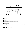
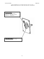
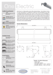
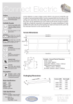
Instruction Manual
INDUCAST
CONTENTS:
Page
SPECIFICATIONS
15
INSTALLATION AND START-UP
16.17
DESCRIPTION OF THE CONTROL PANEL
18.19
DESCRIPTION OF THE PNEUMATIC PANEL
20
MACHINE OPERATION
21.22.23
MAINTENANCE
24.25.26.27
14
Instruction Manual
INDUCAST
■ SPECIFICATIONS ■
DIMENSIONS
HEIGHT:
WIDTH:
DEPTH:
1200 mm
690 mm
560 mm
POWER CONSUMPTION:
VOLTAGE:
FREQUENCY:
WEIGHT:
2500 W
230 V
50/60 Hz
110 Kgs
CHARACTERISTICS
VACUUM LEVEL:
MAX. PRESSURE:
MAX. MELT TEMPERATURE:
MAX. MELTING CAPACITY:
- 0.8 BARS
3.5 BARS
1600°c
60 Grs
CASTING RING DIMENSIONS:
Min. Ø 30 x 55 mm
Max. Ø 100 x 80 mm
GAS:
ARGON
ACCESSORIES
. 4 INDUCAST CASTING RINGS IN STAINLESS STEEL WITH A FLEXIBLE
PLASTIC BOTTOM ( 1X . 3X . 6X . 9X )
. 2 KITS FOR STELLITE, COMPOSED OF TWO FLEXIBLE PLASTIC FLASKS
AND 1 PVC ENDPIECE
. 1 "LARGE-MODEL" STELLITE KIT, COMPOSED OF TWO FLEXIBLE
PLASTIC FLASKS AND 1 PVC ENDPIECE
. 1 VITRIFIED CARBON INSERT.
. 3 WHITE "SILICON DIOXIDE" CRUCIBLES,
. 3 GREY "SILICON CARBIDE" CRUCIBLES
. 1 RING CLAMP
. 3 SILICONE CASTING RINGS ( 1X . 3X . 6X ) with FLEXIBLE ENDPIECE
(3X-6X-9X)
. 1 "umbrella" POURING FUNNEL (top-fed)
15
Instruction Manual
INDUCAST
■ INSTALLATION AND START-UP ■
When unpacking, check that the machine is in perfect condition and report any
damage to the shipper and supplier.
After noting any reservations you may have on the shipping bill, remember to have
the deliveryman countersign it and to confirm your reservations by registered letter
with acknowledgement of receipt.
■ INSTALLATION:
► Place
the machine on a flat surface.
► Make
sure to leave a space of about 5 cm between the back of the
INDUCAST machine and any wall or partition in order to allow room for the
pneumatic connection (compressed air and argon) and for proper ventilation of the
machine.
► Before
turning the machine on, make absolutely certain you have filled
the water tank.
To fill the tank:
. Remove the 4 plastic plugs located on the lower front panel.
. Unscrew the 4 screws on the panel using a Phillips screwdriver.
. Dismount the panel.
. Remove the water pump located on top of the gray tank after having unplugged it
from its power socket.
. Pour 20 liters of water into the tank and then put the pump back in place, taking
care to tighten the clamping collar.
. IMPORTANT: Do not forget to reconnect the water pump to its socket.
. Mount the front panel, then tighten the 4 screws and insert the 4 plugs over the
screw holes.
► After
checking that the mains voltage matches that noted on the
manufacturer's plate, plug the cord into a 10/16A socket fitted with a ground
terminal.
The machine's pneumatic supply requires no lubrication (dry air at a
minimum 3.5-bar pressure).
►
16
Instruction Manual
INDUCAST
IMPORTANT: INDUCAST is equipped with a sensor which monitors the pressure
supply. If there is not at least 2 bars pressure at the feed side of the circuit, the
machine will not operate.
► Connect
the compressed air supply to the machine and check on the
pressure controller to left of the cover that the pressure is approximately 3.5 bars.
►
If not, pull the adjustment knob up to release it.
► Adjust
the pressure and then press down on the knob to lock it back into
position.
NOTE: If the connection between the machine and the laboratory piping is rigid, we
recommend using copper tubing at least 8/10 in diameter, to ensure uniformity in the
installation pipework.
IMPORTANT: Take care not to reverse the Compressed Air and Argon
connections.
INDUCAST does not necessarily require the use of argon.
This casting machine is designed to operate perfectly either with or
without an argon gas supply.
Using ARGON:
Different grades of gas may be used, primarily industrial-grade "U"
ARGON and "NERTAL".
These products are supplied in 4 and 10-m3 cylinders, fitted with the
requisite regulators (0 to 3 bars).
► Connect
the argon source at the point indicated on the back panel of the
machine and set the regulator on the cylinder for 1 bar.
17
Instruction Manual
INDUCAST
■ DESCRIPTION OF THE CONTROL PANEL ■
7
1
8
2
9
3
4
10
5
6
1 ON button
To turn the power on.
2 ARGON cycle control button
This cycle must be selected before starting the cycle.
3 Power control dial
To change the melting time and maximum temperature (monitored visually by
the operator).
4 CYCLE button
To initiate melting and tank evacuation.
18
Instruction Manual
INDUCAST
5 INJECT button
To turn the tank over once the alloy has reached the proper temperature (the
operator determines the appropriate moment for injection).
6 STOP button
To suspend the course of the cycle at any time.
The program is reset to zero and the ON indicator light flashes.
7 ON indicator light
Remains lit during and after the cycle (without pressing the STOP button).
If the STOP button is pressed, it flashes for roughly 2 minutes and then
goes out (at which point the power is off).
8 ARGON indicator light
Stays lit only during an argon cycle.
9 CYCLE indicator light
Indicates that the program has begun. It stays lit until casting is complete.
10 INJECTION indicator light
Lights during injection and stays lit until the end of the cycle.
19
Instruction Manual
INDUCAST
■ DESCRIPTION OF THE PNEUMATIC PANEL ■
INTER 3positions
Position 0 = without vacuum
Position 1 = with regular vacuum
Position 2 = vacuum maxi
GAGE MEASURING tank pressure and vacuum.
(from – 0.8 bar to 3.5 bars).
20
Instruction Manual
INDUCAST
■ MACHINE OPERATION ■
■ DESCRIPTION OF THE "STANDARD" PROGRAM
. Turn the machine on by pressing and holding down the ON button for
roughly 2 seconds (the indicator light goes on).
. Position the crucible containing the alloy.
. Position the casting ring (centered over the crucible). To make sure the ring
is properly centered, rotate it slightly on its axis.
. Close and lock the tank.
. Close the sliding cover (the cycle cannot begin unless the cover is closed).
. Press CYCLE.
. The melting and vacuum (- 0.8 bars) cycle begins. This is a semi-automatic
cycle, in which the operator determines the appropriate moment for
injection.
. Press INJECT
. The tank turns over and compressed air (3.5 bars) is injected.
. The tank remains upside down for ≈ 1 minute.
. The tank returns to its initial position and to atmospheric pressure.
. Open the sliding cover.
. Unlock and open the tank.
IMPORTANT: Avoid leaving the crucible inside the tank after a casting cycle.
21
Instruction Manual
INDUCAST
N.B.: Once the cycle is completed, do not press the STOP button; the machine will
stay on and a new cycle may be started.
Otherwise, the indicator light will begin flashing and the machine will stay on
for 2 minutes. Thereafter, to begin a new cycle, you will need to press the ON
button again (for 2 seconds).
■ DESCRIPTION OF THE "ARGON" PROGRAM
INDUCAST features a special function enabling castings to be carried out in an
argon gas vacuum. To confirm that option, the operator selects the "ARGON" button
on the control panel.
. Turn the machine on by pressing and holding down the ON button for
roughly 2 seconds (the indicator light goes on).
. Position the crucible containing the alloy.
. Position the casting ring (centered over the crucible). To make sure the ring
is properly centered, rotate it slightly on its axis.
. Close and lock the tank.
. Close the sliding cover.
. Press CYCLE.
. The melting and vacuum cycle begins.
. As soon as the proper vacuum level has been reached (- 0.8 bars), ARGON is
injected for roughly 2 seconds.
. The vacuum cycle begins again until the - 0.8-bar pressure setpoint is
reached.
N.B.: During the last three phases, melting continues.
This is a semi-automatic cycle, in which the operator determines the
appropriate moment for injection.
22
Instruction Manual
INDUCAST
. Press INJECT
. The tank turns over and compressed air (3.5 bars) is injected.
. The tank remains upside down for ≈ 1 minute.
. The tank returns to its initial position and to atmospheric pressure.
. Open the sliding cover.
. Unlock and open the tank.
IMPORTANT: Avoid leaving the crucible inside the tank after a casting
cycle.
N.B.: Once the cycle is completed, do not press the STOP button; the machine will
stay on and a new cycle may be started.
Otherwise, the indicator light will begin flashing and the machine will stay on
for 2 minutes. Thereafter, to begin a new cycle, you will need to press the ON
button again (for 2 seconds).
23
Instruction Manual
INDUCAST
■ MAINTENANCE ■
Aside from cleaning the outside panels (without solvents), maintenance of the
INDUCAST machine involves only a few simple operations:
► Clean
the tank cover gasket with alcohol regularly, to make sure it lasts
longer and keeps a tight seal.
► Clean
the inside of the tank (compressed air) from time to time.
Follow the procedure below:
. Turn the machine off.
. Lock the tank .
. Remove the front guard by opening the two catches at the top.
. Rotate the tank ( ≈ 60°) by hand.
. Remove the 4 screws attaching the bottom of the tank.
. Clean the gasket with alcohol if needed and then the inside of the tank, taking care
not to damage the self-induction coil.
. Then repeat the procedure in reverse to reassemble the various components.
IMPORTANT: When repositioning the front guard, first center the lower edge,
holding the two catches open. Raise the guard and then release the catches, checking
that they lock in place on the panels on either side.
► Clean
the dust filter located on the left side of the machine once a year.
Follow the procedure below:
. Turn the machine off.
. Remove the front guard by opening the two catches at the top.
. Remove the 3 fixing screws on the back of the machine, as well as those on the
inside of the motor casing (left-hand side of the machine) .
. Lift and remove the guard.
. Rotate the transparent filter bowl (located immediately next to the tank bearing) and
then disengage it by sliding it downward.
. Clean the filter and then repeat the procedure in reverse to reassemble the various
components.
24
Instruction Manual
INDUCAST
AIR LIQUIDE :
Alsace :
Z.I Sud –Impasse Denis Papin
67400 ILLKIRCH-GRAFFENSTADE
Tel : 03 88 66 86 60
Fax :03 88 66 86 67
Bretagne Ouest :
6 avenue Gabriel Péri
BP 747 56607 LANESTER Cedex
Tel : 02 97 76 85 85
Fax : 02 97 76 85 78
Aquitaine :
Avenue Gaston Cabannes
BP 69 33270 FLOIRAC
Tel : 05 57 80 85 00
Fax : 05 56 32 40 17
Centre :
Z.I les Bicharderies
15 rue de la Forêt
45400 FLEURY LES AUBRAIS
Tel : 02 38 22 90 00
Fax : 02 38 22 90 01
Artois Picardie :
1015 route de LABEUVIERE
BP 2 62920 CHOCQUES
Tel : 03 21 63 25 25
Fax : 03 21 63 25 50
Champagne Ardennes :
4 rue Pierre Maître
BP 2809 51053 REIMS Cedex
Auvergne :
23 rue du Charolais
63039 CLERMONT - FERRAND
Tel : 04 73 98 10 30
Fax : 04 73 98 10 49
Tel : 03 26 84 37 60
Fax : 03 26 09 59 71
Charente Limousin:
Fontastier
Rue des Mesniers
Basse Normandie:
148 rue Basse
14052 CAEN Cedex 4
Tel : 02 31 46 22 20
Fax : 02 31 95 34 66
16710 St YRIEIX S/CHARENTE
Tel : 05 45 68 71 78
Fax : 05 45 68 16 72
Bourgogne:
28 avenue de Stalingrad
BP 57817 DIJON Cedex
Tel : 03 80 73 08 50
Fax : 03 80 73 08 60
Dauphiné Savoie :
Parc d’activités de l’île Gabourd
185 chemin des Mariniers
BP 56 38342 VOREPPE Cedex
Tel : 04 76 50 40 00
Fax : 04 76 50 40 50
Bretagne Armor :
139 route de LORIENT
35042 RENNES Cedex
Tel : 02 23 46 18 00
Fax : 02 23 46 18 60
Flandre Littoral :
Z.I Petite Synthe
Av de la Gironde BP 94
59640 DUNKERQUE
Tel : 03 28 26 75 00
Fax : 03 28 26 70 00
25
Instruction Manual
INDUCAST
AIR LIQUIDE
Franche-comté :
1 rue de l’usine
BP 162 25405 EXINCOURT Cedex
Tel : 03 81 99 53 00
Fax : 03 81 99 53 10
Haute Normandie :
4 av Philippe Lebon
76121 GRAND QUEVILLY Cedex
Tel : 02 32 11 15 00
Fax : 02 32 11 15 15
Ile de France Nord :
Parc Gustave Eiffel
1 rue de l’Europe
93593 LE BLANC MESNIL Cedex
Tel : 01 55 81 55 81
Fax : 01 55 81 55 00
Ile de France Ouest :
5 rue Charles Tellier
78520 LIMAY
Tel : 01 30 98 15 00
Fax : 01 30 98 15 01
Franche-comté :
1 rue de l’usine
BP 162 25405 EXINCOURT Cedex
Tel : 03 81 99 53 00
Fax : 03 81 99 53 10
Haute Normandie :
4 av Philippe Lebon
76121 GRAND QUEVILLY Cedex
Tel : 02 32 11 15 00
Fax : 02 32 11 15 15
Ile de France Sud Est:
ZI les Radars Fleury
21 rue Condorc
91353 GRIGNY Cedex
Tel : 01 69 02 27 27
Fax : 01 69 02 27 28
Loire Vendée :
9 rue de la métalurgie
BP 624
44476 CARQUEFOU Cedex
Tel : 02 40 18 39 00
Fax : 02 28 23 01 51
Lorraine Sud :
93 av du Xxé corps
BP 670 54063 NANCY Cedex
Tel : 03 83 85 70 00
Fax : 03 83 85 70 10
Lorraine Nord :
Derrière le château
57270 RICHEMONT
Tel : 03 82 82 48 30
Fax : 03 82 82 48 40
Méditerraneé :
N°4 6e rue
BP 264 13747 VITROLLES Cedex
Tel : 04 42 10 10 10
Fax : 04 42 10 10 90
Méditerraneé:
rue Claude Daunesse
BP 245 06905 SOPHIA-ANTIPOLIS
Tel : 04 92 96 26 10
Fax : 04 92 96 2619
Midi Pyrénées :
RueMax Planck
BP 245 31677 LABEGE Cedex
Tel : 05 61 39 40 41
Fax : 05 61 39 40 00
Nivernais Yonne:
61 rue Faidherbe
BP 38 58207 NEVERS Cedex
Tel : 03 86 71 46 00
Fax : 03 86 71 46 06
26
Instruction Manual
INDUCAST
AIR LIQUIDE
Nord Picardie:
1430 rue Berthelot
BP 37 59721 DENAIN
Tel : 03 27 14 55 00
Fax : 03 27 14 55 04
Nord Picardie :
Centre de Gros N°3
rue des Hauts de Sainghin
59818 LESQUIN Cedex
Tel : 03 28 55 10 10
Fax : 03 28 55 10 20
Normandie Estuaire:
175 boulevard de Graville
BP 1391 76066 LE HAVRE Cedex
Tel : 02 35 24 61 70
Fax : 02 35 24 61 79
Paris :
25 rue des Hautes Pâtures
97737 NANTERRE Cedex
Tel : 01 41 30 10 10
Fax : 01 41 30 10 50
Rhône et Saône :
Z.I les Echets
01706 MIRIBEL Cedex
Tel : 04 72 26 26 26
Fax : 04 72 26 26 10
Rhône Loire:
15 route d’Yvours
69310 PIERRE-BENITE
Tel : 04 78 86 64 00
Fax : 04 78 86 64 10
Touraine :
37 rue du Cercelé
BP 125 37301 JOUE LES TOURS Cedex
Tel : 02 47 68 47 99
Fax :02 47 68 44 59
Valleé du Rhône:
route de Carpentras
BP 114 Vedène 84965
LE PONTET Cedex
Tel : 04 90 03 70 00
27