1
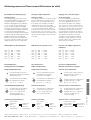
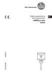
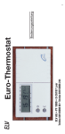
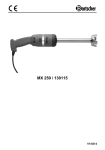
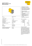
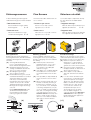
Strömungssensoren Flow Sensors Détecteurs de débit In dieser Anleitung werden folgende TURCK-Strömungssensoren beschrieben: This manual describes TURCK flow sensors as follows: ① Eintauch-Sensoren ① Insertion style sensors Ce mode d'emploi comprend la description des détecteurs de débit TURCK suivants: ① Appareils immergés Unité de détection pour utilisation avec appareils de traitement ③–⑤ Sensoreinheit für nachgeschaltete ③–⑤ Auswertegeräte Inline-Sensoreinheit für nachgeschaltete Auswertegeräte ③ – ⑤ FCS-...-NA... ② Montagehinweise Bei Montage der Geräte mitgelieferte Dichtungen benutzen ( bei NPT-Gewinde sind keine Dichtungen im Lieferumfang enthalten). ( A ) Achtung: Mindestabstand (a ≥ 4 x d) zu Rohrbogen und Querschnittsänderungen beachten! ( B ) Wird Strömungskanal nicht vollständig vom Medium durchströmt, Sensor von unten montieren. ( C ) Sind Ablagerungen möglich, Sensor seitlich montieren. ( D ) Bei der Überwachung von schlecht wärmeleitenden Medien ist auf einen gerichteten Einbau zu achten: z. B. Gase, verschiedene Öle, Flüssigkeiten mit hohem Festtstoffanteil, in Prozessen mit schnellen Temperaturänderungen und bei der Montage aller analogen Strömungssensoren. Bei den Eintauchsensoren sollte der Werkstoffstempel immer im rechten Winkel zur Strömungsrichtung ausgerichtet werden. a ② Appareils inline ② Inline sensor ② Inline-Sensoren ① Sensors for use with a remote signal processor ③ – ⑤ (A) Inline sensors for use with a remote signal processor ③ – ⑤ FCI-...-NA... ③ MK96-... Mounting guidelines Use the supplied sealing rings when mounting the sensors.(Concerning NPT threads, sealing rings are not included in the delivery). ( A ) Attention: please observe the minimum distance (a ≥ 4 x d) to pipe intersections and elbows. Pay attention to possible pipe diameter changes! ( B ) If the pipe is not completely filled by the medium, the sensor must be mounted from below into the flow line. ( C ) If the possibility of deposit build-up exists, mount the sensor from the side. ( D ) When monitoring media with a low thermal conductivity, mounting in flow direction is required: (e.g. gases, some kinds of oils, and liquids containing solid particles) or in processes of rapidly changing temperatures and concerning the mounting of all analogue flow sensors. The insertion sensors must be positioned in a certain angle to the flow direction, i.e. the lable must build a right angle to the flow direction. (B) Unité de détection inline pour utilisation avec appareils de traitement ③ – ⑤ ④ MS96-...-R ⑤ MC96-...R Conseils de montage Utiliser lors du montage les joints d'étanchéité faisant partie de la livraison (pour le filetage NPT les joints ne sont pas inclus). ( A ) Attention: respecter la distance minimale (a ≥ 4 x d) par rapport aux parties coudées et aux changements de section de la tuyauterie! ( B ) Si le tuyau n'est pas entièrement rempli par le fluide, le détecteur doit être monté par le dessous. ( C ) Si des dépôts sont possibles, le détecteur doit être monté latéralement ( D ) Lors du contrôle de milieux ayant une mauvaise conductivité thermique il faut respecter un montage dirigé: p.ex. gaz, différentes huiles, fluides contenant un taux élevé de matières grasses, dans des processus avec des variations de température brusques et lors du montage de tous les détecteurs de débit analogiques. Le cachet de matériel des détecteurs d'immersion doit être aligné perpendiculairement par rapport à la direction du fluide. (C) (D) A4 a d a³4xd Strömungssensoren/Flow sensors/Détecteurs de débit Connection Pin configuration (seen from the view of the contacts) Anschluss Gerätestecker (auf die Kontakte gesehen) 2 BN = braun/brown/brun BU = blau/blue/bleu BK = schwarz/black/noir WH = weiß/white/blanc 1 3 Raccordement Connecteur de l'appareil (vue côté contacts) 4 MK96... mit Sensor/with sensor/avec détecteur ...VP01 Sensor/ sensor/ détecteur ...VN01 +15V 4 BK 4 pnp 5 NC 3 BU 3 pnp 6 NO Sensor/ sensor/ détecteur Strömung/ current/ courant 400 mA K ...11-R/24VDC Strömung/ current/ courant +15V 4 BK 4 npn 5 NC 3 BU 3 npn 6 NO 2 WH 2 7+ 2 WH 2 7+ 1 BN 1 8 1 BN 1 8 Sensor/ sensor/ détecteur 4 BK 4 400 mA K 19,2...28,8 VDC 5 3 BU 3 2 WH 2 ...Li01 Strömung/ current/ courant Sensor/ sensor/ détecteur 1 BN 1 5+ 3 BU 3 6 +15 V +15V 4 BK 4 7+ 2 WH 2 UB 8 1 BN 1 +15V U 6 I Sensor/ sensor/ détecteur 4 BK 16 3 BU 15 1 BN 13 11 +15 V 10 9 1 BN 13 4 Temperatur/ temperature/ température 3 12 () 2 (+) 1 () 10 () 9 zd4 L 19,2...28,8 VDC zd2 L+ d8 z8 2 WH d26 z6 1 BN z26 d12 2 4 BK d32 4 Temperatur/ temperature/ température 3 +15 V 11 +15 V z12 5 12 Strömung 2/ current 2/ courant 2 3 BU z28 7 Strömung 1/ current 1/ courant 1 6 2 WH 14 5 Sensor/ sensor/ détecteur 1 4 BK d28 8 3 BU 15 7 Strömung/ current/ courant 6 2 WH 14 MC96... mit Sensor/with sensor/avec détecteur ...22-R Sensor/ sensor/ détecteur 4 BK 16 8 2 (+) 1 () 3 BU z32 z10 1 Strömung/ current/ courant Temperatur/ temperature/ température d16 z14 2 WH d30 z16 1 BN z30 d20 z18 z20 2 Strömung/ current/ courant Temperatur/ temperature/ température Auswertegeräte / Signal processor / Appareils de traitement séparés 7 8 5 6 9 10 11 12 13 14 15 16 A MS96-12-R 3 4 1 2 230 VAC 1 2 3 4 5 e1 1 Tim [°C] [°C] 25 -20 6 7 MC96-22-R AV [s] 0 E p Tem R MK96-VP01 4...20 mA 7+ 21,6...26,4 VDC 8 19,2...28,8 VDC MS96... mit Sensor/with sensor/avec détecteur ...12-R ...13-R Strömung/ current/ courant 100 A E p Tem 8 [°C] e2 2 Tim Einstellhinweise Schaltausgang Switching output adjustment Réglage de la sortie de commutation Abgleich bei ruhendem Medium: 1. Sensor in den Strömungskanal einbauen, das Gerät einschalten und Bereitschaftszeit abwarten. 2. Mit dem Potentiometer grob und fein am externen Auswertegerät so einstellen, dass die rote LED gerade aufleuchtet. 3. Beim Einsetzen der Strömung sollte mindestens eine grüne LED leuchten. Adjustment with medium at rest: 1. Install the sensor in the flow channel, switch on the device and wait until the availability time has elapsed. 2. Use the potentiometer for rough setting and fine setting until the red LED just starts to light up. 3. At least one green LED should light when the flow starts. Abgleich bei strömenden Medium: 1. Sensor in den Strömungskanal einbauen, Strömung vorgeben und das Gerät einschalten. Bereitschaftszeit abwarten. 2. Mit dem Potentiometer grob und fein am externen Auswertegerät so einstellen, dass eine oder zwei grüne LEDs leuchten. 3. Beim Ausfall der Strömung muss nun die rote LED leuchten. Adjustment with flowing medium: 1. Install the sensor in the flow channel, set the flow and switch on the device. Wait until the standby time has elapsed. 2. Use the potentiometer for rough setting or fine setting until one or two green LEDs light up. 3. As soon as the flow stops the red LED must now light. Réglage en cas de milieu statique: 1. Monter le détecteur dans le tuyau, enclencher l'appareil et attendre la durée de stabilisation avant indication. 2. Régler le potentiomètre "gros" et "fin" de l'appareil de traitement externe jusqu'à ce que la LED rouge s'allume. 3. Dès que le milieu commence à couler, au moins une LED verte doit s'allumer. Réglage en cas de milieu circulant: 1. Monter le détecteur dans le tuyau, programmer le débit et enclencher l'appareil. Attendre le la durée de stabilisation avant indication. 2. Régler le potentiomètre "gros" et "fin" de l'appareil de traitement externe jusqu'à ce que qu'une ou deux LED vertes s'allument. 3. En cas d'arrêt du débit, seule la LED rouge doit s'allumer. LED-Funktion am Auswertegerät LED function at signal processor Fonction des LED à l'appareil commutant LED LED LED LED LED LED E GN E GN E GN E GN E YE E RD Rot (RD): Die Strömung ist ausgefallen oder der vorgegebene Sollwert ist unterschritten. Der Schaltausgang ist nicht geschaltet. LED LED LED LED LED LED E GN E GN E GN E GN E YE E RD Red (RD): The flow has stopped or the predefined setpoint value has not been reached. The switch output is not switched. LED LED LED LED LED LED E GN E GN E GN E GN E YE E RD Rouge (RD): Le débit s'est arrêté ou la valeur de consigne prévue n'est pas atteinte. La sortie de commutation n'est pas commutée. LED LED LED LED LED LED E GN E GN E GN E GN E YE E RD Gelb (YE): Der eingestellte Sollwert ist erreicht. Der Schaltausgang ist geschaltet. LED LED LED LED LED LED E GN E GN E GN E GN E YE E RD Yellow (YE): The set setpoint value is reached. The switch output is switched. LED LED LED LED LED LED E GN E GN E GN E GN E YE E RD Jaune (YE): La valeur de consigne réglée est atteinte. La sortie de commutation est commutée. LED LED LED LED LED LED E GN E GN E GN E GN E YE E RD Grün (GN): Der eingestellte Sollwert ist überschritten. Die Zahl der leuchtenden LEDs ist ein Maß für die relative Sollwertüberschreitung. Der Schaltausgang ist geschaltet. LED LED LED LED LED LED E GN E GN E GN E GN E YE E RD Green (GN): The set setpoint value has been exceeded. The number of LEDs which light is an indication of the relative level of the setpoint value overshoot. The switch output is switched. LED LED LED LED LED LED E GN E GN E GN E GN E YE E RD Vert (GN): La valeur de consigne réglée est dépassée. Le nombre de LED luminantes est une indication pour le dépassement de la valeur de consigne relative. La sortie de commutation est commutée. Strömungssensoren/Flow sensors/Détecteurs de débit Einstellhinweise Analogausgang Analogue output adjustment Réglage de la sortie analogique Analogausgang Der Analogausgang des externen Auswertegerätes MK96-Li01 liefert einen von der Strömungsgeschwindigkeit des Mediums abhängigen Strom im Bereich von 4…20 mA. Der Zusammenhang zwischen Strömungsgeschwindigkeit und dem Ausgangsstrom ist nicht linear. Der Arbeitsbereich wird über die beiden Potentiometer eingestellt. Mit dem Potentiometer (2) wird bei der geringsten zu überwachenden Strömungsgeschwindigkeit der Wert auf 4 mA eingestellt. Mit dem Potentiometer (1) wird bei der höchsten zu überwachenden Geschwindigkeit der Wert auf 20 mA eingestellt. Analogue output The analogue output of the external signal processor MK96-Li01 provides power between 4 to 20 mA dependent on the flow speed of the medium.The relationship between flow speed and output current is non-linear. The operating range is set via two potentiometers. With the potentiometer (2) the lowest flow speed to be monitored is set to the value of 4 mA. With the potentiometer (1) the highest flow speed to be monitored is set to the value of 20 mA. Sortie analogique La sortie analogique de l'appareil de traitement externe MK96-Li01 fournit un courant dépendant de la vitesse d'écoulement du milieu dans la plage de 4...20 mA. La relation entre la vitesse d'écoulement et le courant de sortie n'est pas linéaire. La plage de fonctionnement est réglée par les deux potentiomètres. Le potentiomètre (2) permet de régler la valeur inférieure à 4 mA lorsque la vitesse d'écoulement la plus basse doit être surveillée. Le potentiomètre (1) permet de régler la valeur supérieure à 20 mA lorsque la vitesse d'écoulement la plus élevée doit être surveillée. LED-Funktion am Auswertegerät LED function at signal processor Fonctions des LED à l'appareil de traitement = 20 mA > 16 mA > 12 mA > 8 mA > 4 mA ≤ 4 mA E E E E E E LED LED LED LED LED LED GN GN GN GN GN RD = 20 mA > 16 mA > 12 mA > 8 mA > 4 mA ≤ 4 mA E E E E E E LED LED LED LED LED LED GN GN GN GN GN RD = 20 mA > 16 mA > 12 mA > 8 mA > 4 mA ≤ 4 mA Zusatzfunktionen – Anzeigeelemente und Abgleich Special functions – LEDs and adjustment Fonctions supplémentaires – Eléments d'indication et réglage Temperaturüberwachung Temperature monitoring Contrôle de la température Rote LED leuchtet auf, wenn Temperatur-Sollwert erreicht bzw. überschritten wird. The red LED illuminates when the temperature setpoint is reached or overranged. [°C] [°C] -20 100 Potentiometer zur Einstellung des Temperatur-Sollwerts (von -20 °C…+100 °C). Ausschaltverzögerung Strömung AV [s] 0 25 E -20 DIP-Schalter: paarweise links = Ausschaltverzögerung A E paarweise rechts = Einschaltverzögerung 100 [°C] Potentiometer for adjustment of the temperature setpoint (from -20 °C…+100 °C). Switch-off delay flow Potentiometer zur Einstellung der Ausschaltverzögerung von 0…25 s, wirkt auf den Schaltausgang für die Strömungsüberwachung. Schaltverzögerung Strömung A La LED rouge s'allume quand la température de consigne est atteinte ou dépassée. AV [s] 0 25 E Potentiometer for adjustment of the switch-off delay from 0…25 s which affects the flow monitoring output. DIP-switch: paired left = switch OFF delay 100 Temporisation à l'enclenchement Switch-on/off delay A -20 Potentiomètre pour le réglage de la température de consigne (de -20 °C à +100 °C). AV [s] 0 25 Potentiomètre pour le réglage de la temporisation au déclenchement de 0 à 25 s. Agit sur la sortie de commutation du contrôle du débit. Temporisation à l'enclenchement A E paired right = switch ON delay A E Commutateurs DIP: vers la gauche: A E vers la droite: temporisation temporisation déclenchement à l'enclench Irrtümer und Änderungen vorbehalten / Subject to change without notice / Sous réserve de modifications • © Hans Turck GmbH & Co. KG 2007 Hans Turck GmbH & Co. KG • D–45466 Mülheim/Ruhr • Tel. 0208/4952-0 • Fax 0208/4952-264 • E-Mail: [email protected] • www.turck.com *D100356ßß0107* GN GN GN GN GN RD D100356 0107 E E E E E E LED LED LED LED LED LED