1
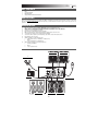
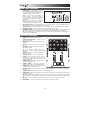
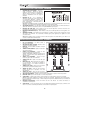
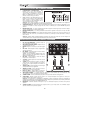
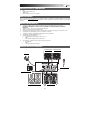
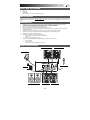
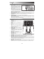
QUICKSTART GUIDE ENGLISH ( 3 – 5 ) MANUAL DE INICIO RÁPIDO ESPAÑOL ( 6 – 8 ) GUIDE D’UTILISATION RAPIDE FRANÇAIS ( 9 – 11 ) GUIDA RAPIDA ITALIANO ( 12 – 14 ) KURZANLEITUNG DEUTSCH ( 15 – 17 ) BOX CONTENTS M101 AC Power Adapter Quickstart Guide Safety & Warranty Information Booklet REGISTRATION Please go to http://www.numark.com to register your M101. Registering your product ensures that we can keep you up-to-date with any last-minute product developments and provide you with world-class technical support, should you run into any problems. GROUND RULES 1. 2. 3. 4. 5. 6. 7. 8. 9. 10. Make sure all items listed in the BOX CONTENTS section are included in the box. READ SAFETY & WARRANTY INFORMATION BOOKLET BEFORE USING THE PRODUCT. Study the connection diagram in this guide. Place mixer in an appropriate position for operation. Make sure all devices are turned off and all faders and gain knobs are set to “zero.” Connect all stereo input sources as indicated in the diagram. Connect the stereo outputs to power amplifier(s), tape decks, and/or other audio sources. Plug all devices into AC power. Switch everything on in the following order: • Audio input sources (i.e. turntables, CD players, etc.) • Mixer • Last, any amplifiers or output devices When turning off, always reverse this operation by: • Turning off amplifiers • Mixer • Last, any input devices CONNECTION DIAGRAM TURNTABLE TURNTABLE HEADPHONES POWER MICROPHONE HOUSE AMP CD PLAYER 3 CD PLAYER REAR PANEL FEATURES 1. POWER SWITCH – Turns the mixer on and off. Turn on the mixer after all input devices have been connected and before you turn on amplifiers. Turn off amplifiers before you turn off the mixer. 2. AC IN – Use the included power adapter to connect the mixer to a power outlet. While the power is switched off, plug the power supply into the mixer first, then plug the power supply into a power outlet. 6 1 2 3 4 5 4 5 3 4 5 4 5 Note: The mixer is designed to work with the included power supply only. Using an incompatible power supply could result in damage to the unit. 3. MASTER OUTPUT (RCA) – Use standard RCA cables to connect this output to a speaker or amplifier system. The level of this output is controlled by the MASTER knob on the top panel. 4. LINE INPUTS (RCA) – Connect line-level devices, such as CD players, samplers or audio interfaces, to these inputs. 5. PHONO INPUTS (RCA) – Connect phono-level devices, such as turntables, to these inputs. 6. GROUNDING TERMINAL – If you are using phono-level turntables with a grounding wire, connect the grounding wire to these terminals. If you experience a low “hum” or “buzz”, this could mean that your turntables are not grounded. Note: Some turntables have a grounding wire built into the RCA connection and, therefore, nothing needs to be connected to the grounding terminal. TOP PANEL FEATURES 1. POWER LED – Illuminates when the mixer is on. 2. STEREO LEVEL INDICATOR – Displays the audio level of the Program mix. 3. MASTER – This control adjusts the output volume of the Program mix. 4. MIC GAIN – Adjusts the audio level of the microphone signal. 5. MIC TREBLE – Adjusts the high (treble) frequencies of the microphone channel. Tip: If you experience feedback when using a microphone at loud levels, try turning down the high frequencies. 9 3 10 7 11 11 8 12 12 13 13 4 9 5 10 6 1 2 6. MIC BASS – Adjusts the low (bass) frequencies of the microphone channel. 7. CUE GAIN – Adjusts the level of the headphone audio. 8. CUE MIX – Turn to mix between Channels 1 and 2 in the headphones. When all the way to the left, only Channel 1 will be heard. When all the way right, only Channel 2 will be heard. 9. CHANNEL GAIN – Adjusts the corresponding channel’s pre-fader and pre-EQ gain level. 10. CHANNEL TREBLE – Adjusts the high (treble) frequencies of the audio on the corresponding channel. 11. CHANNEL BASS – Adjusts the low (bass) frequencies of the audio on the corresponding channel. 12. INPUT SELECTOR – Selects the input source to be routed to the corresponding channel. Input jacks are located on the rear panel. 13. CHANNEL FADER – Adjusts the audio level on the corresponding channel. 14. CROSSFADER – Blends audio playing between Channels 1 and 2. Sliding this to the left plays channel 1 and sliding to the right plays Channel 2. 14 15 16 Note: The crossfader is user-replaceable if it should ever wear out. Simply remove the facepanel, then remove the screws holding it in position. Replace the fader with a quality authorized replacement from your local Numark retailer only. 15. MIC INPUT – Connect ¼” microphones to this input. The microphone controls are located on the top panel. 16. HEADPHONES – Connect your ¼” headphones to this output for cueing and mix monitoring. 4 CONTENIDO DE LA CAJA M101 Adaptador de CA Guía de inicio rápido Folleto de información sobre la seguridad y la garantía REGISTRO Visite http://www.numark.com y registre su M101. El registro de su producto asegura que podamos mantenerle actualizado con los desarrollos de productos de último momento y brindarle apoyo técnico de categoría mundial en caso de que tenga algún problema. REGLAS BÁSICAS 1. 2. 3. 4. 5. 6. 7. 8. 9. 10. Asegúrese de que todos los artículos indicados en “Contenido de la caja" estén incluidos en la caja. LEA EL FOLLETO DE INFORMACIÓN SOBRE LA SEGURIDAD Y LA GARANTÍA ANTES DE UTILIZAR EL PRODUCTO. Estudie el diagrama de conexión incluido en esta guía. Coloque el mezclador en una posición adecuada para su funcionamiento. Asegúrese que todos los dispositivos estén apagados y que todos los faders y perillas de ganancia estén en posición «cero». Conecte todas las fuentes de entrada estéreo como se indica en el diagrama. Conecte las salidas estéreo a los amplificadores de potencia, bandejas de cinta magnética y/o otras fuentes de audio. Enchufe todos los dispositivos al suministro de corriente alterna. Encienda todo en el siguiente orden: • fuentes de entrada de audio (por ejemplo, giradiscos, reproductores de CD, etc.) • el mezclador • por último, cualquier amplificador o dispositivo de salida Al apagar, realice siempre esta operación en sentido inverso: • apague los amplificadores • el mezclador • por último, cualquier dispositivo de entrada DIAGRAMA DE CONEXIÓN GIRADISCOS GIRADISCOS AURICULARES MICRÓFONO ALIMENTACIÓN AMPLIFICADOR DE AUDITORIO REPRODUCTORS DE CD 5 CARACTERÍSTICAS DEL PANEL TRASERO 1. 2. 3. 4. 5. 6. INTERRUPTOR DE ENCENDIDO – Enciende y apaga el mezclador. Encienda el mezclador después de desconectar todos los dispositivos de entrada y antes de encender los amplificadores. 6 Apague los amplificadores antes de apagar el mezclador. 1 ENTRADA DE CA – Use el adaptador de 3 4 5 4 5 alimentación incluido para conectar el mezclador a 3 4 5 4 5 un tomacorriente alimentado. Mientras está 2 desconectada la alimentación eléctrica, enchufe la fuente de alimentación al mezclador primero, y luego al tomacorriente. Para tener en cuenta: El mezclador está diseñado para funcionar con la fuente de alimentación de CA de 9 V-1.5 únicamente . Si usa una fuente de alimentación incompatible se puede dañar la unidad. SALIDA MAESTRA (RCA) – Use cables RCA estándar para conectar esta salida maestra a un sistema de altavoces o amplificador. El nivel de esta salida se controla con la perilla MASTER del panel superior. ENTRADAS DE LÍNEA (RCA) – Estas entradas se usan para conectar dispositivos de nivel de línea, tales como reproductores de CD, muestreadores o interfaces de audio. ENTRADAS FONOGRÁFICAS (RCA) – Estas entradas se usan para conectar dispositivos de nivel fonográfico, como giradiscos. TERMINAL DE TIERRA – Si usa giradiscos de nivel fonográfico con cable de conexión a tierra, asegúrese de conectar dicho cable a estos terminales. Si se experimenta un zumbido grave, puede significar que sus giradiscos no están conectados a tierra. Nota: Algunos giradiscos tienen el cable de conexión a tierra incorporado a la conexión RCA y, por lo tanto, no es necesario conectar nada al terminal de tierra. CARACTERÍSTICAS DEL PANEL SUPERIOR 1. 2. 3. 4. 5. 6. 7. 8. 9. 10. 11. 12. 13. 14. 15. 16. LED DE ENCENDIDO – Se ilumina cuando el mezclador está encendido. INDICADOR DE NIVEL ESTÉREO – Muestra el nivel 9 4 9 1 3 de audio de la mezcla del programa. MAESTRA – Ajusta el volumen de salida de la mezcla de programa. 5 2 7 10 10 GANANCIA DE MICRÓFONO – Ajusta el nivel de audio de la señal de micrófono. AGUDOS DE MICRÓFONO – Ajusta las altas 8 6 11 11 frecuencias (agudos) del canal de micrófono. Consejo: Si experimenta realimentación cuando usa un micrófono con niveles altos, pruebe disminuyendo las 12 12 altas frecuencias. GRAVES DE MICRÓFONO – Ajusta las bajas frecuencias (graves) del canal de micrófono. GANANCIA DE CUE – Ajusta el nivel del audio para 13 13 auriculares. MEZCLA DE CUE – Gírelo para mezclar los canales 1 y 2 en los auriculares. Si se desliza a la izquierda se reproduce el canal 1. Si se desliza a la derecha se reproduce el canal 2. GANANCIA DE CANAL – Ajusta el nivel de ganancia preecualización y pre-fader del audio del canal. 14 TREBLE DE CANAL – Ajusta las altas frecuencias (agudos) del audio que se reproduce en el canal correspondiente. 15 16 GRAVES DE CANAL – Ajusta las bajas frecuencias (graves) del audio que se reproduce en el canal correspondiente. SELECTOR DE ENTRADAS – Permite seleccionar la fuente de entrada que se aplica al canal correspondiente. FADER DE CANAL - Ajusta el nivel de audio en el canal correspondiente. CROSSFADER – Combina el audio entre los canales asignados a los lados izquierdo y derecho del crossfader. Nota: El usuario puede reemplazar el crossfader en caso de que se desgaste. Simplemente, retire el panel frontal y luego los tornillos que lo mantienen sujeto. Cambie el fader por un repuesto de calidad autorizado por su vendedor de Numark más cercano. ENTRADA DE MICRÓFONO – Conecte un micrófono de 1/4” a esta entrada. Los controles de micrófono se encuentran en el panel superior. AURICULARES – Conecte sus auriculares de 1/4" a esta salida para búsqueda de punto inicial (cue) y monitoreo de la mezcla. Los controles de la salida para auriculares se encuentran en el panel superior. 6 CONTENU DE LA BOÎTE M101 Câble d'alimentation CA Guide d'utilisation simplifié Le livret des consignes de sécurité et des informations concernant la garantie ENREGISTREMENT Veuillez visiter le site internet http://www.numark.com pour enregistrer votre nouvelle M101. L'enregistrement des produits vous permet d'être informé sur les toutes dernières nouveautés concernant les produits et de vous offrir un soutien technique de niveau international, si vous en aviez besoin. RÈGLES DE BASE 1. 2. 3. 4. 5. 6. 7. 8. 9. 10. Assurez-vous que tous les articles énumérés dans le contenu de la boîte de ce guide sont inclus dans la boîte. VEUILLEZ LIRE LE LIVRET DES CONSIGNES DE SÉCURITÉ ET DES INFORMATIONS SUR LA GARANTIE AVANT D'UTILISER LE PRODUIT. Examinez le schéma de connexion de ce guide. Placez la console de mixage en position de fonctionnement. Assurez-vous que tous les appareils sont hors tension et que tous les atténuateurs et le gain sont réglés à « zéro ». Connectez toutes les sources d'entrées stéréo tel qu'indiqué sur le schéma. Branchez toutes les sorties aux amplificateurs de puissance, aux lecteurs de cassette et aux sources audio. Branchez tous les appareils à une prise de courant alternatif (AC). Mettre tous les appareils sous tension dans l'ordre suivant. • Sources d'entrée audio (c.-à-d.tourne-disques, lecteurs de disques compacts, etc.) • Consoles de mixage • En dernier, tous amplificateurs ou appareils de sortie Pour mettre hors tension, toujours inverser l'opération : • Éteindre les amplificateurs • Consoles de mixage • En dernier, tous les appareils d'entrée SCHÉMA DE CONNEXION TABLES TOURNANTES ÉCOUTERS DJ MICROPHONE ALIMENTATION AMP LOCAUX LECTEURS 7 CARACTÉRISTIQUES DU PANNEAU ARRIÈRE 1. 2. 3. 4. 5. 6. L'INTERRUPTEUR D'ALIMENTATION – Met l’appareil sous et hors tension. Branchez la console après avoir branché tous les appareils et 6 avant de mettre les amplificateurs sous tension. Mettez les amplificateurs hors tension avant de 1 mettre la console de mixage hors tension. 3 4 5 4 5 AC IN – Utilisez le câble d’alimentation inclus pour brancher la console dans une prise d’alimentation 3 4 5 4 5 2 murale. Lorsque la console de mixage est hors tension, branchez le câble d'alimentation dans la console, puis dans la prise de courant. Remarque: Cette console de mixage est conçue pour fonctionner avec le câble d'alimentation fourni uniquement. L’utilisation d’un autre câble d’alimentation pourrait endommager l’appareil. SORTIE MASTER (RCA) – Utilisez des câbles RCA standards afin de brancher cette sortie à un haut-parleur ou à un système de sonorisation. Le niveau du signal de cette sortie est commandé par le bouton MASTER du panneau supérieur. ENTRÉES LINE (RCA) – Ces entrées permettent de brancher des appareils à niveau ligne tels que lecteurs de disques compacts, échantillonneurs ou autres interfaces audio. ENTRÉES PHONO (RCA) – Ces entrées permettent de brancher des appareils à niveau phono, tels que les tables tournantes. BORNE DE MISE À LA TERRE – Si vous utilisez des tables tournantes avec fils de mise à la terre, assurez-vous de brancher le fils à cette borne. S’il y a un ronflement ou du bruit, il se pourrait que vos tables tournantes ne soient pas mises à la terre. Remarque: Certaines tables tournantes fabriquées récemment sont dotées d'un fil de mise à la terre intégré à la connexion RCA, et donc, n'ont pas besoin d’être reliées à la borne de mise à la terre. CARACTÉRISTIQUES DU PANNEAU SUPÉRIEUR 1. 2. 3. 4. 5. 6. 7. 8. 9. 10. 11. 12. 13. 14. 15. 16. LED DEL D’ALIMENTATION – S’allume lorsque la console de mixage est sous tension. INDICATEUR DU NIVEAU STÉRÉO – Indique le niveau 9 4 9 1 3 audio du programme en cours. MASTER – Ajuste les niveaux de la sortie du Program mix. 5 2 10 7 10 MIC GAIN – Permet d'ajuster le niveau du signal audio de l’entrée microphone. MIC TREBLE – Permet d'ajuster le niveau des hautes 8 fréquences du canal microphone. 6 11 11 Conseil : Si vous entendez du feedback lorsque vous utilisez le microphone à de hauts niveaux, essayez de 12 12 diminuer les hautes fréquences. MIC BASS – Permet d'ajuster le niveau des basses fréquences du canal microphone. CUE GAIN – Permet d’ajuster les niveaux du canal du casque d'écoute. 13 13 CUE MIX – Permet de mixer les canaux 1 et 2 dans le casque d’écoute. Lorsqu’il est déplacé vers la gauche, le canal 1 joue. Lorsqu’il est déplacé vers la droite, le canal 2 joue. GAIN DU CANAL – Permet d’ajuster le niveau du signal audio pré-atténuateur et pré-égalisation. 14 TREBLE DU CANAL – Permet d'ajuster le niveau des hautes fréquences du canal correspondant. BASS DU CANAL – Permet d'ajuster le niveau des 15 16 basses fréquences de l’audio du canal correspondant. SÉLECTEUR D’ENTRÉE – Ce réglage permet de sélectionner la source d’entrée qui est acheminée au canal correspondant. Les entrées sont situées sur le panneau arrière. CHANNEL FADER – Uilisez cet atténuateur pour ajuster le niveau de l’audio acheminé au Program mix. CROSSFADER – Effectue un fondu entre les canaux 1 et 2. Lorsqu’il est déplacé vers la gauche, le canal 1 joue. Lorsqu’il est déplacé vers la droite, le canal 2 joue. Remarque: Ce potentiomètre est remplaçable par l’utilisateur s’il devait se détériorer. Retirez tout simplement le panneau avant et dévissez les vis qui le retiennent en position. Remplacez le potentiomètre avec un autre potentiomètre de qualité autorisé provenant de votre détaillant Numark local. ENTRÉE MIC – Permet de brancher un microphone ¼ po. Les commandes microphone sont situées sur le panneau supérieur. CASQUE D’ÉCOUTE – Permet de brancher un casque d’écoute ¼ po pour la pré écoute. Les commandes casque d’écoute sont situées sur le panneau supérieur. 8 CONTENUTI DELLA CONFEZIONE M101 Adattatore di alimentazione CA Guida rapida Libretto di istruzioni di sicurezza e garanzia REGISTRAZIONE Recarsi alla pagina http://www.numark.com per registrare il M101. La registrazione del prodotto garantisce che possiamo tenervi aggiornati con tutti gli ultimissimi sviluppi del prodotto e offrirvi assistenza tecnica di livello mondiale, in caso di eventuali problemi. NORME FONDAMENTALI 1. 2. 3. 4. 5. 6. 7. 8. 9. 10. Assicurarsi che tutti gli elementi elencati sul frontespizio della presente guida si trovino nella confezione. LEGGERE ATTENTAMENTE IL LIBRETTO DELLE ISTRUZIONI DI SICUREZZA PRIMA DI UTILIZZARE IL PRODOTTO. Studiare con cura lo schema dei collegamenti fornito nella guida. Sistemare il mixer in una posizione adeguata all’uso. Assicurarsi che tutti i dispositivi siano spenti e che tutti i fader e le manopole di guadagno siano impostati su “zero”. Collegare tutte le sorgenti di ingresso stereo come indicato nello schema. Collegare le uscite stereo ad amplificatori, mangianastri e/o altre sorgenti audio. Collegare tutti i dispositivi all’alimentazione CA. Accendere tutto nel seguente ordine: • sorgenti di ingresso audio (giradischi, lettori CD, ecc.) • il mixer • infine, eventuali amplificatori o dispositivi di uscita Al momento dello spegnimento, invertire questa operazione spegnendo: • gli amplificatori • il mixer • infine, qualsiasi dispositivo di ingresso SCHEMA DEI COLLEGAMENTI GIRADISCHI GIRADISCHI CUFFIE MICROFONO ALIMENTAZIONE AMPLIFICATORE SALA LETTORI CD 9 CARATTERISTICHE PANNELLO POSTERIORE 1. 2. 3. 4. 5. 6. INTERRUTTORE DI ALIMENTAZIONE (POWER) – Accende e spegne il mixer. Accendere il mixer dopo aver collegato tutti i dispositivi d’ingresso e prima di accendere gli amplificatori. Spegnere gli 6 amplificatori prima di spegnere il mixer. AC IN – Servirsi dell’adattatore di alimentazione in 1 dotazione per collegare il mixer ad una presa di 3 4 5 4 5 alimentazione. Ad alimentazione spenta, collegare l’alimentazione elettrica innanzitutto nel mixer, 3 4 5 4 5 2 quindi ad una presa elettrica. Nota bene: il mixer è concepito per funzionare unicamente con l’alimentatore CA da 9V-1,5A in dotazione. L’uso di un alimentatore incompatibile può danneggiare l’apparecchio. USCITA MASTER (RCA) – Servirsi di cavi standard RCA per collegare questa uscita Master ad una cassa o ad un sistema di amplificatori. Il livello di questa uscita è controllato tramite la manopola Master sul pannello superiore. INGRESSI DI LINEA (RCA) – Collegare dispositivi a livello di linea quali lettori CD, campionatori o interfacce audio a questi ingressi. INGRESSI PHONO (RCA) – Collegare dispositivi a livello phono, ad esempio giradischi, a questi ingressi. TERMINALE DI MESSA A TERRA – Se si utilizzano giradischi a livello phono dotati di cavo di messa a terra, questo va collegato a questi terminali. Se si verifica un “ronzio” o un “brusio” basso, ciò può significare che i giradischi non sono messi a terra. Nota bene: alcuni giradischi hanno il cavo di messa a terra incorporato nel collegamento RCA e, di conseguenza, non è necessario collegare nulla al terminale di messa a terra . CARATTERISTICHE PANNELLO SUPERIORE 1. 2. 3. 4. 5. 6. 7. 8. 9. 10. 11. 12. 13. 14. 15. 16. LED DI ALIMENTAZIONE – Si illumina quando il mixer è acceso. INDICATORE DI LIVELLO STEREO – Mostra a display 9 4 9 1 3 il livello audio del mix di Programma. MASTER – Regola il volume di uscita del mix di Programma. 5 2 7 10 10 MIC GAIN (guadagno mic) – Regola il volume dell’ingresso del microfono. MIC TREBLE (acuti mic) – Regola le frequenze alte 8 6 11 11 (treble) del canale del microfono. Suggerimento: in caso di ritorno durante l’uso di un microfono ad alti livelli, provare ad abbassare le 12 12 frequenze alte. MIC BASS (bassi mic) – Regola le frequenze basse (bass) del canale del microfono. CUE GAIN (guadagno Cue) – Regola il livello dell’audio delle cuffie. 13 13 CUE MIX – Passa a mixare l’audio del Canale 1 & Canale 2 in cuffia. Spostare questo cursore a sinistra per ascoltare il Canale 1 o verso destra per ascoltare il Canale 2. CHANNEL GAIN (guadagno canale) – Regola il guadagno audio pre-fader del canale corrispondente. 14 CHANNEL TREBLE (acuti di canale) – Regola le frequenze alte (treble) del canale corrispondente. CHANNEL BASS (bassi di canale) – Regola le 15 16 frequenze basse (bass) del canale corrispondente. SELETTORE DI INGRESSI – Seleziona la sorgente di ingresso che verrà convogliata al canale corrispondente. FADER CANALE – Regola il livello audio inviato al mix di programma (Program). CROSSFADER – Miscela l’audio tra i Canali 1 e 2. Facendolo scorrere verso sinistra, viene riprodotto il Canale 1. Facendolo scorrere verso destra viene riprodotto il Canale 2. Nota bene: il crossfader è sostituibile dall’utente in caso di usura. Rimuovere il pannello anteriore e le viti che lo tengono in posizione. Sostituire il fader con un ricambio autorizzato acquistato presso il proprio rivenditore Numark locale. INGRESSO MIC – Collegare un microfono da ¼” a questo ingresso. I comandi del microfono si trovano sul pannello superiore. CUFFIE – Collegare le cuffie da ¼” a questa uscita per il monitoraggio del mix e il cueing. I comandi dell’uscita cuffie si trovano sul pannello superiore. 10 INHALT DER VERPACKUNG M101 AC Netzteil Kurzanleitung Broschüre mit den Sicherheits- und Garantierichtlinien REGISTRIERUNG Registrieren Sie Ihren M101 bitte auf http://www.numark.de. Dadurch geben Sie uns die Möglichkeit, Ihnen Informationen bei Produktaktualisierungen zukommen zu lassen und Ihnen bei möglichen Problemen den bestmöglichen technischen Support zu bieten. GRUNDREGELN 1. 2. 3. 4. 5. 6. 7. 8. 9. 10. Überprüfen Sie, dass sich alle auf der Vorderseite der Anleitung abgebildeten Bestandteile im Karton befinden. LESEN SIE VOR DER VERWENDUNG DES PRODUKTS DIE SICHERHEITSHINWEISE. Sehen Sie sich die Anschlussübersicht in dieser Anleitung an. Stellen Sie den Mixer in einer für den Betrieb geeigneten Position auf Achten Sie darauf, dass alle Geräte ausgeschaltet sind und dass alle Fader und Gain Regler Ihres Mixers auf dem niedrigsten Wert stehen. Verbinden Sie alle Stereo Eingangsquellen, wie in der Anschlussübersicht gezeigt, mit dem Mixer. Schließen Sie die Stereo Ausgänge an Verstärker, Kassettendecks oder andere Audiogeräte an. Schließen Sie alle Geräte an den Stromkreis an. Schalten Sie die Geräte in der folgenden Reihenfolge ein: • Audio Eingangsquellen (z.B. Turntables, CD Player, usw.) • Mixer • Zuletzt Verstärker und Ausgangsgeräte Schalten Sie Ihr System IMMER in genau der umgekehrten Reihenfolge aus, indem Sie: • Zuerst Verstärker • Dann den Mixer • Und am Schluss die Eingangsquellen ausschalten ANSCHLUSSÜBERSICHT PLATTENSPIELER PLATTENSPIELER KOPFHÖRER MIKROFON STROM HOUSE VERSTÄRKER CD SPIELER 11 CD SPIELER ÜBERSICHT ÜBER DIE RÜCKSEITE 1. 2. 3. 4. 5. 6. POWER SCHALTER – Mit diesem Schalter können Sie den Mixer einschalten, nachdem alle Kabelverbindungen vorgenommen wurden. So 6 vermeiden Sie Beschädigungen an Ihren Geräten. Schalten Sie den Mixer vor den Verstärkern ein 1 und schalten Sie Ihre Verstärker aus, bevor Sie den Mixer ausschalten. 3 4 5 4 5 AC IN – Verwenden Sie das beiliegende Netzteil, 3 4 5 4 5 2 um den Mixer mit einer Steckdose zu verbinden. Verbinden Sie, während das Gerät ausgeschaltet ist, das Netzteil zuerst mit dem Mixer und stellen Sie erst dann die Verbindung zur Steckdose her. Hinweis: Dieser Mixer funktioniert ausschließlich mit dem mitgelieferten Netzteil. Die Verwendung eines falschen Netzteils führt zu Beschädigungen am Gerät. MASTER AUSGANG (RCA) – Verbinden Sie diesen Ausgang mit einem PA System, Aktivmonitoren oder einer HiFi Anlage. Die Lautstärke dieses Ausgangs wird mit dem MASTER Regler auf der Mixer Vorderseite geregelt. LINE EINGÄNGE (RCA) – Schließen Sie hier Geräte mit Linepegelsignalen, wie CD Player, Sampler oder Audio Interfaces, an. PHONO-EINGÄNGE (RCA) – Zum Anschluss von Phono-Geräten, wie Plattenspieler. GROUNDING TERMINAL – Bei der Verwendung von Phono Pegel Turntables mit einem Massekabel müssen Sie dieses an diese Erdungspins anschließen. Sollten Sie ein tiefes Brummen oder andere Klangstörungen hören, sind Ihre Turntables möglicherweise nicht geerdet. Hinweis: Bei einigen Turntables ist die Masseverbindung in die Chinch (RCA) Verbindung integriert – bei diesen Geräten benötigen Sie dann keine zusätzliche Masseverbindung. ÜBERSICHT ÜBER DIE OBERSEITE 1. 2. 3. 4. 5. 6. 7. 8. 9. 10. 11. 12. 13. 14. 15. 16. EIN/AUS LED – Leuchtet auf, wenn das Mischpult eingeschaltet ist. STEREOPEGELANZEIGE – Zeigt den Audio Level des 9 4 9 1 3 Program Mix an. MASTER – Steuert die Ausgangslautstärke des Program Mixes. 5 2 7 10 10 MIC GAIN – Stellt die Lautstärke des Mikrofonkanals ein. MIC TREBLE – Stellt die Höhen für den Mikrofonkanal 8 6 11 11 ein. Tipp: Falls es bei der Verwendung des Mikrofons zu Rückkopplungen kommt, vermindern Sie die hohen 12 12 Frequenzen mit diesem Regler. MIC BASS – Stellt die Bässe für den Mirofonkanal ein. CUE–LAUTSTÄRKE – Stellt die Lautstärke des Kopfhörerausgangs ein. 13 13 CUE MIX-REGLER – Überblendet der Cue Mix-Regler die Kanälen 1 & 2 im Kopfhörer. Wird der Schieberegler nach links bewegt, wird Kanal 1 gehört, bei Schieben nach rechts Kanal 2. KANAL-GAIN – Justiert die Audio Pre-Fader und PreEQ Pegel im entsprechenden Kanal ein. 14 KANAL-HÖHEN – Stellt die Höhen des Signals im entsprechenden Kanal ein. KANAL-BÄSSE – Stellt die Bässe des Signals im entsprechenden Kanal ein. 15 16 EINGABEWAHL – Zur Auswahl der Eingabequelle, die and den entsprechenden Kanal geleitet wird. Die Eingangsbuchsen befinden sich auf der Rückseite des Geräts. KANAL-FADER – Bestimmt den Audiopegel, der zum Program Mix gesendet wird. CROSSFADER – Audioüberblendung zwischen den Kanälen 1 und 2. Wird der Crossfader nach links geschoben, wird Kanal 1 abgespielt. Bewegt man den Crossfader nach rechts, hört man Kanal 2. Hinweis: Der Crossfader kann im Falle von Abnutzung leicht vom Benutzer ausgewechselt werden. Dazu wird einfach die Abdeckung abgenommen, dann die Befestigungsschrauben des Faders entfernen. Der Fader sollte nur mit einem vom Numark-Fachhändler authorisierten Ersatzteil ersetzt werden. MIC EINGANG – Verbinden Sie Ihr Mikrofon mit einem 6,3 mm Klinkenkabel mit diesem Eingang. Die Regler für das Mikrofon befinden sich auf der Oberseite des Mixers. KOPFHÖRER – Schließen Sie hier Ihren Kopfhörer mit 6,3 mm Klinkenstecker an, um Signale vorhören und Cue Funktionen verwenden zu können. Die Regler für den Kopfhörerausgang befinden sich auf der Oberseite des Mixers. 12 SPECIFICATIONS INPUTS Line: 10 kΩ input impedance 90 mV rms sensitivity for 1.22 V output Phono: 47 kΩ input impedance 1.1 mV rms sensitivity @ 1 kHz for 1.22 V output 600 Ω input impedance unbalanced Mic: 1.15 mV rms sensitivity for 1.22V output 67 mV rms max input OUTPUTS Line: 7.35 V rms max Headphone: 0.5 W into 47 Ω DISTORTION < 0.01% SIGNAL-TO-NOISE RATIO (maximum output; JIS-A weighted) Line: > 97 dB Phono: > 81 dB Mic: > 96 dB FREQUENCY RESPONSE Line: 20 Hz – 20 kHz (±0.5 dB) Phono: ±1 dB except for controlled attenuation of -3 dB @ 20 Hz to reduce rumble and feedback Mic: 20 Hz – 15 kHz (±0.5 dB) CHANNEL EQUALIZER Treble: +10 / -28 dB @ 15 kHz Bass: +12 / -32 dB @ 60 Hz MIC EQUALIZER Treble: +/-12 dB @ 15 kHz Bass: +/-12 dB @ 100 Hz POWER CONSUMPTION 3.7 W typical 6.3 W with full headphone output THIS DEVICE COMPLIES WITH PART 15 OF THE FCC RULES. OPERATION IS SUBJECT TO THE FOLLOWING TWO CONDITIONS: (1) THIS DEVICE MAY NOT CAUSE HARMFUL INTERFERENCE, AND (2) THIS DEVICE MUST ACCEPT ANY INTERFERENCE RECEIVED, INCLUDING INTERFERENCE THAT MAY CAUSE UNDESIRED OPERATION. www.numark.com MANUAL VERSION 1.0 14