1
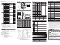
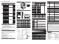
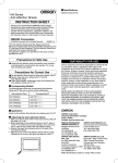
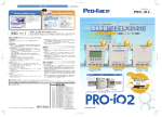
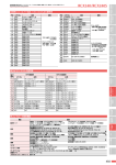
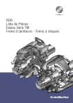
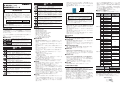
注 意 形 3G3RX-□-V1 高機能型汎用インバータ 軽度の発火、発熱、機器破損がまれに起こるおそれがあります。 端子(+1、P/+2、N/-)に抵抗器を直接接続しないでください。 軽度の傷害がまれに起こるおそれがあります。 安全を確保するための停止装置を設置してください。 ※保持ブレーキは安全を確保するための停止装置ではありません。 取扱説明書 このたびは、インバータ形 3G3RX シリーズ V1 タイプをお買い求 めいただきまして、誠にありがとうございます。 この製品を安全に正しくご使用いただくために、お使いになる前に、 この取扱説明書と安全上のご注意および下記のマニュアルを熟読し、 機器の知識、安全上の情報、注意事項のすべてについて習熟してから 使用してください。また、お読みになったあとも、いつも手元におい て使用してください。 マニュアル名称 マニュアル番号 3G3RX ユーザーズマニュアル SBCE-367 制動抵抗器や回生制動ユニットの発熱により、中程度のやけどが まれに起こるおそれがあります。 必ず指定された制動抵抗器や回生制動ユニットを使用し、制動抵抗 器を使用する場合には、抵抗器の温度を監視するサーマルリレーを 設置してください。また、制動抵抗器や回生制動ユニットの異常過 熱時にインバータの電源を OFF するシーケンスを組んでください。 製品内部には高電圧部分があり、短絡させると製品の破損や物的損 害がまれに起こるおそれがあります。設置や配線時には切り粉やリ ード線くずなどの金属物が製品内部に入らないようにカバーをつけ るなどの処置を行ってください。 負荷の短絡により物的損害がまれに起こるおそれがあります。 インバータの電源側にはインバータ容量に応じた配線用遮断器 (MCCB) を設置するなどの安全対策を施してください。 けがのおそれがあります。 分解や修理、改造は行わないでください。 オムロン株式会社 ©OMRON Corporation 2012 All Rights Reserved. ・LCD デジタルオペレータおよび不要になった電池の廃棄については、 地方自治体により規制を受ける場合があります。それぞれの自治体規 制に従って廃棄してください。 電池を廃棄する際は、電池をテープなどで絶縁してから廃棄してくだ さい。 0194437-6B NT205F 安全上の要点 ■設置・保管 安全上のご注意 ■安全に使用していただくための表示と意味 この取扱説明書では、インバータ形 3G3RX シリーズ V1 タイプ を安全にご使用いただくために、注意事項を次のような表示と記 号で示しています。 ここで示した注意事項は、安全に関する重大な内容を記載してい ます。 必ず守ってください。表示と記号は次のとおりです。 ■警告表示の意味 危険 取り扱いを誤った場合に、危険な状況が起こりえて、 死亡または重傷を受ける可能性が想定される場合、 および深刻な物的損害の発生が想定される場合。 注意 取り扱いを誤った場合に、危険な状況が起こりえて、 中程度の傷害や軽傷を受ける可能性が想定される場合 および物的損害だけの発生が想定される場合。 ■警告表示 危 険 万一の場合、感電による重度の傷害が起こるおそれがあります。 入力電源 OFF を確認してから正しく配線してください。 万一の場合、感電による重度の傷害が起こるおそれがあります。 配線作業は、電気工事の専門家が行ってください。 万一の場合、感電による重度の傷害が起こるおそれがあります。 配線変更、スライドスイッチ (SW1) の変更、オペレータ・オプ ション類の脱着、冷却ファンの交換はインバータの入力電源を OFF にしてから行ってください。 万一の場合、感電・発火による重度の傷害が起こるおそれがあり ます。 接地端子は必ずアースしてください。 (200V 級:D 種接地、400V 級:C 種接地) 万一の場合、感電による重度の傷害が起こるおそれがあります。 通電中および電源遮断後 10 分以内は端子台カバーを外さないで ください。 万一の場合、感電による重度の傷害が起こるおそれがあります。 濡れた手でオペレータ、スイッチ類を操作しないでください。 万一の場合、感電による重度の傷害が起こるおそれがあります。 緊急遮断入力機能が働いた状態になっても、主電源が遮断された わけではありません。製品の確認は、インバータの入力電源を OFF にしてから行ってください。 やけどのおそれがあります。 通電中や電源遮断後のしばらくの間は、インバータのフィン、制 動抵抗器、モータなどは高温になる場合がありますので触れない でください。 下記環境下での保管および使用は避けてください。 ・日光が直接当たる場所 ・周囲温度が仕様を超える場所 ・相対湿度が仕様を超える場所 ・温度の変化が急激で結露するような場所 ・腐食性ガス、可燃性ガスのある場所 ・可燃物またはその近くの場所 ・ちり、ほこり、塩分、鉄粉が多い場所 ・水、油、薬品などの飛まつがかかる場所 ・本体に直接振動や衝撃が伝わる場所 ■輸送・設置・配線 ・部品の故障、製品故障の原因となります。強い衝撃を与えたり、落下 させたりしないでください。 ・運搬時は、フロントカバー・端子台カバーを持たずにフィンを持って ください。 ・インバータの入力電源定格電圧と交流電源の電圧が一致していること を確認してください。 ・製品が破損しますので、制御入出力端子に交流電源を接続しないでく ださい。 ・端子台のねじは確実に締め付けてください。また、配線は本体を据え 付けてから行ってください。 ・本製品の出力 (U、V、W) に三相誘導モータ以外の負荷を接続しない でください。 ・次のような場所で使用する際は、遮断対策を十分に行ってください。 機器破損の原因となります。 静電気などによるノイズが発生する場所 強い磁界が生じる場所 電源線が近くを通る場所 ・立上げ時、調整時、メンテナンス時、交換時にパラメータを誤って設 定すると予期せぬ動作が起きるおそれがあります。 十分な確認を行った後、運転に移行してください。 ・DriveProgramming を使用する場合は、プログラムデータが正常に ダウンロードできたことを確認してから動作を開始してください。 ■運転・調整 ・本製品は低速から高速までの設定ができますので、使用するモータ設 備の許容範囲を十分に確認したあとで運転を行ってください。 ・保持ブレーキが必要な場合は、別に用意してください。 ・多機能出力が出力中に、DriveProgramming が停止すると、出力状 態を保持したままになりますので、周辺機器を停止させるなど安全対 策を施してください。 ・DriveProgramming で時刻機能を使用して制御する場合、LCD デジ タルオペレータの電池消耗で予期せぬ動作が起きるおそれがあります。 電池消耗は、時刻データが初期値に戻ったことで検出し、インバータ またはプログラムを停止させるなどの対策を行ってください。LCD デ ジタルオペレータが取り外されたり、断線したりした場合、 DriveProgramming は時刻機能で待機状態になります。 ■保守・点検 ・保守や点検、部品交換を行う際は、安全を確保したあとで行ってくだ さい。 ・コンデンサの寿命は周囲温度に影響されます。ユーザーズマニュアル に記載されている製品寿命カーブをご覧ください。コンデンサが寿命 に達し、製品として機能を果たさなくなった場合には、本体の交換が 必要となります。 ・本インバータの使用周囲温度は最大 50℃としてください(VT 定格は 40℃)。 ・電解コンデンサの放電時間は最低でも 10 分です。感電のおそれがあります。 ・各機種につき適切なモータ過負荷保護 ( 最大 FLA120%) を使用してく ださい。 ・インバータに搭載されている短絡保護は、分岐回路の保護をするわけで はありません。National Electric Code や、ほかの相当する規格に基づ いた分岐回路の保護回路をご使用ください。 ・モータの加熱保護機能は、本製品にはありません。 ■締め付けトルクと電線サイズ 締め付けトルクと配線サイズは下記表を適用してください。 リチウム一次電池(過塩素酸塩含有率が 6ppb 以上)を組み込んだ製 品が米国・カリフォルニア州へ輸出・経由される場合、次の表示が義 務化されています。 入力電圧 Perchlorate Material - special handling may apply. See www.dtsc.ca.gov/hazardouswaste/perchlorate 形 3G3AX-OP05 はリチウム一次電池(過塩素酸塩含有率が 6ppb 以 上)を搭載しています。 形 3G3AX-OP05 が組み込まれた貴社製品を米国・カリフォルニア州 へ輸出される場合は、貴社製品の梱包箱または輸送箱などに上記表示 を行っていただくようお願いします。 ・電池は液漏れ、破裂、発熱、発火などのおそれがありますので、+、の短絡、充電、分解、加熱、火への投入、強い衝撃を与えることなど は絶対に行わないでください。また、床に落下させるなどして強い衝 撃を与えてしまった電池は、液漏れするおそれがありますので絶対に 使用しないでください。 ・電池の交換は熟練した技術者によって行われることが UL 規格で定め られています。 交換作業は熟練した技術者がご担当ください。また、本マニュアルに 記載した方法で交換してください。 ・LCD デジタルオペレータの表示が寿命で認識できなくなった場合は、 LCD デジタルオペレータを交換してください。 200V 級 締め付け トルク (N・m) 主回路端子台 配線サイズ (AWG) 出力 適用インバータ形式 (kW) (形 3G3RX-) 0.4 A2004-V1 0.75 A2007-V1 1.5 A2015-V1 2.2 A2022-V1 3.7 A2037-V1 10 5.5 A2055-V1 8 7.5 A2075-V1 6 11 A2110-V1 6 または 4 14 1.8 4.0 15 A2150-V1 2 18.5 A2185-V1 1 22 A2220-V1 1 または 1/0 30 A2300-V1 2/0 または 1/0 並列 37 A2370-V1 使用上の注意 45 A2450-V1 ■取り付け 55 A2550-V1 ・取付方向は縦長方向で壁取り付けとしてください。 また、取り付け壁の材質は金属板等の不燃材としてください。 ■再始動選択機能 ・再始動選択機能 (b001, b008) を使用すると、アラーム停止時に突然 始動しますので、近寄らないでください。 ・運転信号を入れたままアラームリセットを行うと突然始動しますので、 運転信号が切れていることを確認してからアラームリセットを行って ください。 ■瞬停・不足電圧減速停止機能 ・瞬停・不足電圧減速停止機能選択 (b050) で再始動を選択した場合、 電源復帰後に突然再始動しますので注意してください。 ■運転停止指令 ・オペレータのストップボタンは機能設定したときだけ有効ですので、 緊急停止スイッチは別に用意してください。 ・通電中に信号チェックを行い、誤って制御入力端子に電圧が印加され るとモータが突然動き出すことがあります。信号チェックを行う際は 安全を確かめて行ってください。 ■保守・部品の交換 ・インバータは多数の部品で構成されており、これらの部品が正常に 動作することによって本来の機能を発揮します。電子部品の中には、 使用条件によっては保守が必要なものがあります。長期間にわたって インバータを正常に動作させるためには、これらの部品の耐用年数に 合わせた定期点検。部品交換が必要です。 (JEMA 発行「汎用インバータの定期点検のお勧め」から引用) ・冷却ファンが寿命に達したときは、ファンを交換してください。 ■製品の廃棄 ・本製品を廃棄する際は、条例などの規則に従ってください。 UL対応に関するご注意 、出力(U/T1,V/T2,W/T3)端 ・本インバータの入力(R/L1,S/L2,T/L3) 子の配線は、UL 認定の 60/75℃の銅電線をご使用ください。 (適用機種:3G3RX-A4055-V1, A4075-V1,A4110-V1 以外の機種) ・本インバータの入力(R/L1,S/L2,T/L3) 、出力(U/T1,V/T2,W/T3)端 子の配線は、UL 認定の 75℃の銅電線をご使用ください。 (適用機種:3G3RX-A4055-V1, A4075-V1,A4110-V1) ・本インバータは、電流実効値が 100kA 以下に制限されている最大電圧 240V の回路にて、ブレーカを使用することによって UL 規格の出力短 絡試験を実施しており、この回路に適合しています。 (200V 級) ・本インバータは、電流実効値が 100kA 以下に制限されている最大電圧 480V の回路にて、ブレーカを使用することによって UL 規格の出力短 絡試験を実施しており、この回路に適合しています。 (400V 級) ・本インバータの据え付けは汚染度 2 の環境下としてください。 0.4 A4004-V1 0.75 A4007-V1 1.5 A4015-V1 2.2 A4022-V1 20.0 350 (kcmil) または 2/0 並列 19.6 14 1.8 A4037-V1 5.5 A4055-V1 12 7.5 A4075-V1 10 11 A4110-V1 8 15 A4150-V1 A4220-V1 6 または 4 30 A4300-V1 3 37 A4370-V1 45 A4450-V1 55 A4550-V1 75 B4750-V1 90 B4900-V1 110 B411K-V1 132 B413K-V1 配線サイズ (AWG) 4.0 6 A4185-V1 22 制御回路端子台 8.8 4/0 または 1/0 並列 3.7 400V 級 18.5 4.9 4.9 1 20.0 2/0 1/0 並列 3/0 並列 35.0 締め付けトルク Ft-Ibs (N・m) 制御入出力端子 30 ∼ 16 0.16 ∼ 0.19 0.22 ∼ 0.25 リレー出力端子 30 ∼ 14 0.37 ∼ 0.44 0.5 ∼ 0.6 ■圧着端子 配線に使用する圧着端子は、電線サイズに合ったものを使用し、UL および CSA 認定の丸型圧着端子を使用してください。 また、圧着する際はメーカ指定の工具を使用してください。 丸端子 電線カバー 電線 入力電圧 出力 適用インバータ形式 (kW) (形 3G3RX-) 0.4 0.75 1.5 2.2 3.7 5.5 7.5 200V 級 11 15 18.5 22 30 37 45 55 0.4 0.75 1.5 2.2 3.7 5.5 7.5 11 15 400V 級 18.5 22 30 37 45 55 75 90 110 132 A2004-V1 A2007-V1 A2015-V1 A2022-V1 A2037-V1 A2055-V1 A2075-V1 A2110-V1 A2150-V1 A2185-V1 A2220-V1 A2300-V1 A2370-V1 A2450-V1 A2550-V1 A4004-V1 A4007-V1 A4015-V1 A4022-V1 A4037-V1 A4055-V1 A4075-V1 A4110-V1 A4150-V1 A4185-V1 A4220-V1 A4300-V1 A4370-V1 A4450-V1 A4550-V1 B4750-V1 B4900-V1 B411K-V1 B413K-V1 ブレーカまたは ヒューズ ヒューズ (Type J) ヒューズ (Type J) または 逆時限回路ブレーカ ヒューズ (Type J) ヒューズ (Type J) または 逆時限回路ブレーカ 定格 (A) 30 30 30 30 30 100 100 100 125 125 125 225 225 250 300 20 20 20 20 20 40 40 40 75 75 75 100 100 150 150 225 225 300 350 ■モータ過負荷保護 本インバータは、モータ過負荷保護機能を搭載しています。 本機能は、以下のパラメータを適切に設定することにより機能します。 ・b012:第 1 電子サーマルレベル設定 ・b212:第 2 電子サーマルレベル設定 ・ b312:第 3 電子サーマルレベル設定 また、2 台以上のモータをインバータに接続する場合は、上記の電子 サーマルでモータを保護できません。それぞれのモータに外部サーマル リレーを設置してください。 EC指令対応 主回路 端子台 制御回路 N/-, P/+2, +1,RB AM,AMI,FS,FV,FE, FI,FC,MP,FW,S8, S7,S6,S5,S4,S3,S2, S1,SC,PSC,P24,PC, P5,P4,P3,P2,P1,TH M5 A2110, A4110 M6 M5 M6 A003 A004 第 1 基底周波数 A2150, A2185 M6 A4150 ∼ A4220 M6 M6 A019 多段速選択 A020 A021 ∼ A035 M8 M4 M6 M8 A4300 M6 M6 M6 A2370 M8 M8 M8 A4370 M8 M8 M8 A2450 M8 M8 M8 A4450, A4550 M8 M8 M8 M8 M10 A2550 M10 B4750 ∼ B413K ねじサイズ 締め付けトルク A2004 ∼ A2037 A4004 ∼ A4037 A2055, A2075, A2110 A4055, A4075, A4110 A2150, A2185, A2220 A4150, A4185, A4220 A2300, A4300 D 150 130 255 241 140 210 189 260 246 170 250 229 390 376 190 310 265 540 510 195 390 300 550 520 250 480 380 700 670 250 B4750, B4900 390 300 700 670 270 480 380 740 710 DCリアクトル ∼ サーミスタ 周波数 指令 (500 ∼2kΩ) S1 ∼S8 S8 SC コモン TH FS 周波数指令電源 FV 周波数指令(電圧) FE 周波数指令補助(電圧) FC コモン FI 周波数指令(電流) b084 0.7N・m (max. 0.8) 1.2N・m (max. 1.4) 2.4N・m (max. 4.0) M6 M8 M10 4.5N・m (max. 4.9) 8.1N・m (max. 8.8) *(max. 20.0) 20.0N・m (max. 22.0) b180 C001 ∼ C008 C021 ∼ C025 C026 H003 H004 第 1 多段速指令 0 0.0, /始動 [b082] ∼最高周波数 [A004] 多段速指令 1 ∼ 15 0.0, /始動 [b082] ∼最高周波数 [A004] 第 1 電子サーマルレベル 0.00 ∼定格出力電流 00:全表示/ 01:機能個別表示/ 02:ユ 表示選択 ーザ設定 +b037 / 03:データコンペア表 示/ 04:ベーシック表示 00:初期化無効/ 01:異常モニタクリア 02:データ初期化/ 03:異常モニタクリア 初期化選択 + データ初期化/ 04:異常モニタクリア + データ初期化 +DriveProgramming クリア 初期化実行 00:機能無効/ 01:初期化・モード選択実行 多機能入力 S1 ∼ S8 選択 01:RV(逆転)/02 ∼ 05:CF1 ∼ 4(多 段速バイナリ 1 ∼ 4)など 多機能出力 P1 ∼ P5 選択 00:RUN(運転中)/ 01:FA1(定速到 達時)/ 02:FA2(設定周波数以上到達) 03:OL(過負荷予告)/ 04:OD(PID 多機能リレー出力 偏差過大)/ 05:AL(アラーム)など (MA,MB) 機能選択 第 1 モータ容量選択 第 1 モータ極数選択 0.20 ∼ 160.0 2/4/6/8/10 ご承諾事項 内容 各機能モード間を移行します。 また、変更途中の設定データをキャンセルし てパラメータ No. の表示に移行します。 ※モードキーを 3 秒間押し続けると、d001 にジャンプします。 モードキー インクリメント パラメータ No. や設定データの変更を行いま キー す。 デクリメント キー 270 当社商品は、一般工業製品向けの汎用品として設計製造されています。従いまして、 次に掲げる用途での使用を意図しておらず、お客様が当社商品をこれらの用途に使用 される際には、当社は当社商品に対して一切保証をいたしません。ただし、次に掲げる 用途であっても当社の意図した商品用途の場合や特別の合意がある場合は除きます。 (a)高い安全性が必要とされる用途(例:原子力制御設備、燃焼設備、航空・宇宙設備、鉄道設備、 昇降設備、娯楽設備、医用機器、安全装置、その他生命・身体に危険が及びうる用途) (b)高い信頼性が必要な用途(例:ガス・水道・電気等の供給システム、24 時間 連続運転システム、決済システムほか権利・財産を取扱う用途など) (c)厳しい条件または環境での用途(例:屋外に設置する設備、化学的汚染を被る 設備、電磁的妨害を被る設備、振動・衝撃を受ける設備など) (d)カタログ等に記載のない条件や環境での用途 * (a) から (d) に記載されている他、本カタログ等記載の商品は自動車(二輪車含む。以下同じ) オペレータでの運転を選択時に、運転を開始 します。 正転・逆転は、F004 の設定に従います。 RUN キー 向けではありません。自動車に搭載する用途には利用しないで下さい。自動車搭載用商品に ついては当社営業担当者にご相談ください。 * 上記は適合用途の条件の一部です。当社のベスト、総合カタログ、データシート等最新版の カタログ、マニュアルに記載の保証・免責事項の内容をよく読んでご使用ください。 STOP/RESET キーが有効設定時、運転を停 STOP/RESET 止します。 キー 異常発生時はリセットキーになります。 MB 多機能 MA リレー出力 MC コモン P1 P5 PC RS+ ) RS485 通信 RSRP ) 終端抵抗用 RSAM アナログモニタ(電圧) AM アナログモニタ(電流) MP デジタルモニタ ( PWM 出力) ) オプショ ン ※多機能リレー出力の工場出荷時設定は、MA が b 接点、 MB が a 接点です。 パラメータ No. から設定データ表示に移行し ます。 また、設定データを確定し記憶します。 エンターキー M ∼ 正転指令 b037 第 1 最高周波数 キーの説明 制動抵抗器 (22kW 以下の機種は 回生制動回路内蔵) +1 P/+2 N/- RB U/T1 R/L1 V/T2 S/L2 W/T3 T/L3 R T Ro To P24 多機能出力 PSC P1 ∼P5 FW コモン S1 多機能入力 b012 M5 ■標準接続図 三相AC200V 三相AC400V M3 M4 名称 A2370, A2450 A4370, A4450, A4550 A2550 B411K, B413K 締め付けトルク M3 M3 ねじサイズ [mm] 運転指令選択 M5 A2300 H1 A002 M5 ■外形寸法 H 周波数指令選択 運転方向選択 A2055, A2075 A4055, A4075 M8 W1 A001 0.01 ∼ 3600. 0.01 ∼ 3600. 00:正転 /01:逆転 00:オペレータ(ボリューム)形 3G3AX-OP01 接続時に有効)/ 01:制御回路端子台/ 02:オペレータ(F001)/ 03:Modbus 通信 04:オプション 1 / 05:オプション 2 / 06:パルス列周波数/ 07:DrivePrograming 10:周波数演算結果 01:制御回路端子台/ 02:オペレータ(F001) 03:Modbus 通信/ 04:オプション 1 05:オプション 2 30. ∼最高周波数 [A004] 30. ∼ 400. 00:バイナリ(4 端子で 16 段可) 01:ビット(7 端子で 8 段可) 第 1 減速時間 1 M4 M6 W MA, MB, MC 第 1 加速時間 1 M4 M8 形 3G3RX-□-V1 リレー モニタまたはデータ範囲 機能名称 F002 F003 F004 A2004 ∼ A2037 M4 A4004 ∼ A4037 A2220 W W1 パラメータ No. オプション 取付と配線 ■製造者およびEU代理人 製造者 :OMRON Corporation 京都市下京区塩小路堀川東入 (形 3G3RX□-V1) 制御回路 端子台 ■本インバータの規格 EU 代理人:Omron Europe B.V. Wegalaan 67-69, NL-2132 JD Hoofddorp, The Netherlands R/L1, S/L2, T/L3, Ro, アース U/T1, To (記号) V/T2, W/T3 形式 デジタルオペレータ ・EMC 指令に適合するための、接地・ケーブル選定・その他の条件に ついては、該当するマニュアルを参照ください。 ・この商品は「class A」 (工業環境商品)です。住宅環境でご利用される と電波妨害の原因となる可能性があります。その場合には、電波妨害に 対する適切な対策が必要となります。 本インバータは以下の規格に適合しています。 ・200V 級: EN61800-3 category C3 ・400V 級: EN61800-3 category C3 主回路 オプション基板 取付位置 D プのヒューズまたはブレーカを使用してください。 ■端子記号、ねじサイズ、締め付けトルク 各部の名称 H1 H ■ブレーカとヒューズ UL 規格に対応される場合は、必ず電源側に UL 規格品のクラス J タイ ●製品に関するお問い合わせ先 お客様相談室 名称 マニュアル番号 PG ボード 形 3G3AX-PG □□ ユーザーズマニュアル CX-Drive オペレーションマニュアル LCD デジタルオペレータ 形 3G3AX-OP05 ユーザーズマニュアル DriveProgramming ユーザーズマニュアル DeviceNet 通信ユニットユーザーズマニュアル CompoNet 通信ユニット ユーザーズマニュアル SBCE-350 SBCE-351 SBCE-375 SBCE-368 SBCE-369 SBCE-370 SBCE-371 パラメータ一覧 パラメータ No. d001 d002 F001 機能名称 モニタまたはデータ範囲 出力周波数モニタ 0.0∼400.0 0.0 ∼ 9999 始動 [b082] ∼最高周波数 [A004] 出力電流モニタ 出力周波数設定/モニタ オムロン 0120-919-066 関連マニュアル 回生制動ユニット 形 3G3AX-RBU □□ ユーザーズマニュアル クイック 携帯電話・PHS・IP電話などではご利用いただけませんので、下記の電話番号へおかけください。 電話 055-982-5015(通話料がかかります) ■営業時間:8:00∼21:00 ■営業日:365日 ●FAXやWebページでもお問い合わせいただけます。 FAX 055-982-5051 / www.fa.omron.co.jp ●その他のお問い合わせ 納期・価格・サンプル・仕様書は貴社のお取引先、または貴社 担当オムロン販売員にご相談ください。 オムロン制御機器販売店やオムロン販売拠点は、Webページで ご案内しています。 お断りなく仕様などを変更することがありますのでご了承ください。 0194437-6B NT205F TYPE 3G3RX--V1 High-function General-purpose Inverter INSTRUCTION MANUAL Thank you for purchasing 3G3RX, V1 type Inverter. To ensure safe operation, please be sure to read the safety precautions provided in this document along with all of the user manuals for the inverter. Please be sure you are using the most recent versions of the user manuals. Keep this instruction manual and all of the manuals in a safe location and be sure that they are readily available to the final user of the products. Manual Name 3G3RX User’s Manual Cat.No. I578-E1 OMRON Corporation OMRON Corporation 2012 All Rights Reserved. 0194437-6B NT205XF Safety Precautions Indications and Meanings of Safety Information In this user’ s manual, the following precautions and signal words are used to provide information to ensure the safe use of the 3G3RX, V1 type Inverter.The information provided here is vital to safety. Strictly observe the precautions provided. Meanings of Signal Words WARNING Indicates an imminently hazardous situation which, if not avoided, is likely to result in serious injury or may result in death. Additionally there may be severe property damage. CAUTION Indicates a potentially hazardous situation which, if not avoided, may result in minor or moderate injury or in property damage. Alert Symbols in this Document WARNING Turn off the power supply and implement wiring correctly. Not doing so may result in a serious injury due to an electric shock. Wiring work must be carried out only by qualified personnel. Not doing so may result in a serious injury due to an electric shock. Do not change wiring and slide switches (SW1), put on or take off Operator and optional devices, replace cooling fans while the input power is being supplied. Doing so may result in a serious injury due to an electric shock. Be sure to ground the unit. Not doing so may result in a serious injury due to an electric shock or fire. (200V class:type-D grounding, 400V class:type-C grounding) Do not remove the terminal cover during the power supply and 10 minutes after the power shut off. Doing so may result in a serious injury due to an electric shock. Do not operate the Operator or switches with wet hands. Doing so may result in a serious injury due to an electric shock. Inspection of the Inverter must be conducted after the power supply has been turned off. Not doing so may result in a serious injury due to an electric shock. The main power supply is not necessarily shut off even if the emergency shut off function is activated. Do not touch the Inverter fins, braking resistors and the motor, which become too hot during the power supply and for some time after the power shut off. Doing so may result in a burn. CAUTION Do not connect resistors to the terminals (+1, P/+2, N/-) directly. Doing so might result in a small-scale fire, heat generation or damage to the unit. Install a stop motion device to ensure safety. Not doing so might result in a minor injury. (A holding brake is not a stop motion device designed to ensure safety.) Be sure to use a specified type of braking resistor/regenerative braking unit. In case of a braking resistor, install a thermal relay that monitors the temperature of the resistor. Not doing so might result in a moderate burn due to the heat generated in the braking resistor/regenerative braking unit. Configure a sequence that enables the Inverter power to turn off when unusual over heating is detected in the braking resistor/ regenerative braking unit. The Inverter has high voltage parts inside which, if short-circuited, might cause damage to itself or other property. Place covers on the openings or take other precautions to make sure that no metal objects such as cutting bits or lead wire scraps go inside when installing and wiring. Take safety precautions such as setting up a molded-case circuit breaker (MCCB) that matches the Inverter capacity on the power supply side. Not doing so might result in damage to property due to the short circuit of the load. Do not dismantle, repair or modify the product. Doing so may result in an injury. Precautions for Safe Use Installation and Storage Do not store or use the product in the following places. Locations subject to direct sunlight. Locations subject to ambient temperature exceeding the specifications. Locations subject to relative humidity exceeding the specifications. Locations subject to condensation due to severe temperature fluctuations. Locations subject to corrosive or flammable gases. Locations subject to exposure to combustibles. Locations subject to dust (especially iron dust) or salts. Locations subject to exposure to water, oil, or chemicals. Locations subject to shock or vibration. Transporting, Installation, and Wiring Do not drop or apply strong impact on the product. Doing so may result in damaged parts or malfunction. Do not hold by the front cover and terminal cover, but hold by the fins during transportation. Confirm that the rated input voltage of the Inverter is the same as AC power supply voltage. Do not connect an AC power supply voltage to the control input/ output terminals. Doing so may result in damage to the product. Be sure to tighten the screws on the terminal block securely. Wiring work must be done after installing the unit body. Do not connect any load other than a three-phase inductive motor to the U, V, and W output terminals. Take sufficient shielding measures when using the product in the following locations. Not doing so may result in damage to the product. Locations subject to static electricity or other forms of noise. Locations subject to strong magnetic fields. Locations close to power lines. If a parameter is set incorrectly when starting up, adjusting, maintaining, or replacing, an unexpected operation may occur. Perform the operation after enough confirmation. When using DriveProgramming, confirm that the program data is downloaded normally before starting the operation. Operation and Adjustment Be sure to confirm the permissible range of motors and machines before operation because the inverter speed can be changed easily from low to high. Provide a separate holding brake if necessary. If DriveProgramming stops during multi-function output, the output status is held. Take safety precautions such as stopping peripheral devices. If the clock command is used in DriveProgramming, an unexpected operation may occur due to weak battery or removal of the LCD digital operator. Take measures such as detecting a weak battery or removal of the LCD digital operator (the clock data detects the initial setting and all zero), stopping the Inverter or programs. Maintenance and Inspection Be sure to confirm safety before conducting maintenance, inspection or parts replacement. The capacitor service life is influenced by the ambient temperature. Refer to "Product Life Curve" described in the manual. When a capacitor reaches the end of its service life and does not work as the product, you need to replace the capacitor. When disposing of LCD digital operators and wasted batteries, follow the applicable ordinances of your local government. When disposing of the battery, insulate it using tape. Caution -Risk of Electric Shock- Capacitor discharge time is at least 10 minutes. Solid state motor overload protection reacts with max. 120% of FLA. Integral solid state short circuit protection dose not provide branch circuit protection. Branch circuit protection must be provided in accordance with the NEC and any additional local codes. Motor over temperature protection is not provided by the drive. The following display must be indicated when products using lithium primary batteries (with more than 6 ppb of perchlorate) are transport to or through the State of California, USA. AVERTISSEMENT: ne retirez pas le capot avant pendant l’alimentation et 10 minutes après l’arrêt de l’alimentation. Cela peut entraîner de grave blessure due à un choc électrique. Perchlorate Material - special handling may apply. See www.dtsc.ca.gov/hazardouswaste/perchlorate The 3G3AX-OP05 has the lithium primary battery (with more than 6 ppb of perchlorate).Label or mark the above display on the exterior of all outer shipping packages of your products when exporting your products which the 3G3AX-OP05 are installed to the State of California, USA. Do not short + and -, charge, disassemble, heat, put into the fire, or apply strong impact on the battery. The battery may leak, explode, produce heat or fire. Never use the battery which was applied strong impact due to such as fall on the floor, it may leak. UL standards establish that the battery shall be replaced by an expert engineer. The expert engineer must be in charge of the replacement and also replace the battery according to the method described in this manual. When the display of LCD digital operator can not be recognized due to the service life, replace the LCD digital operator. Precautions for Safe Use Installation Mount the product vertically on a wall the product’ s longer sides upright. The material of the wall has to be noninflammable such as a metal plate. Restart Selection Function Terminal Tightening Torque and Wire Size The wire size range and tightening torque for field wiring terminals are presented in the tables below. Input Motor Voltage Output (kW) 0.4 0.75 1.5 2.2 3.7 5.5 7.5 11 200V 15 Class 18.5 22 30 37 45 Do not come close to the machine when using the Restart Selection function (b001, b008) because the machine may abruptly start when stopped by an alarm. Be sure to confirm the RUN signal is turned off before resetting the alarm because the machine may abruptly start. Deceleration Stop Function Do not come close to the machine when selecting reset in the Deceleration Stop Function (b050) because the machine may abruptly start after the power is turned on. Operation Stop Command Provide a separate emergency stop switch because the STOP Key on the Operator is valid only when function settings are performed. When checking a signal during the power supply and the voltage is erroneously applied to the control input terminals, the motor may start abruptly. Be sure to confirm safety before checking a signal. Maintenance and Parts Replacement Inverters contain components and will operate properly only when each component operates normally. Some of the electrical components require maintenance depending on application conditions. Periodic inspection and replacement are necessary to ensure proper long-term operation of Inverters. (Quoted from The Recommendation for Periodic Maintenance of a General-purpose Inverter published by JEMA.) When a cooling fan reaches the end of its service life, replace it. Product Disposal Comply with the local ordinance and regulations when disposing of the product. UL Cautions The warnings and instructions in this section summarize the procedures necessary to ensure an inverter installation complies with Underwriters Laboratories guidelines. These devices are open type AC Inverters with three phase input and three phase output. They are intended to be used in an enclosure. They are used to provide both an adjustable voltage and adjustable frequency to the AC motor. The inverter automatically maintains the required voltage-Hz ration allowing the capability through the motor speed range. Use 60/75°C Cu wire only. For models 3G3RX-V1 series except for models 3G3RX-A4055-V1, 3G3RX-A4075, 3G3RX-A4110-V1. Use 75°C Cu wire only. For models 3G3RX-V1 series for 3G3RX-A4055-V1, 3G3RX-A4075, 3G3RX-A4110-V1. Suitable for use on a circuit capable of delivering not more than 100k rms symmetrical amperes, 240 V maximum. (For models: 200 V class) Suitable for use on a circuit capable of delivering not more than 100k rms symmetrical amperes, 480 V maximum. (For models: 400 V class) Install device in pollution degree 2 environment. Maximum Surrounding Air Temperature 50°C (VT rating is 40°C). 400V Class Inverter Model 3G3RXA2004-V1 A2007-V1 A2015-V1 A2022-V1 A2037-V1 A2055-V1 A2075-V1 A2110-V1 A2150-V1 A2185-V1 A2220-V1 A2300-V1 A2370-V1 A2450-V1 55 A2550-V1 0.4 0.75 1.5 2.2 3.7 5.5 7.5 11 15 18.5 22 30 37 45 55 75 90 110 132 A4004-V1 A4007-V1 A4015-V1 A4022-V1 A4037-V1 A4055-V1 A4075-V1 A4110-V1 A4150-V1 A4185-V1 A4220-V1 A4300-V1 A4370-V1 A4450-V1 A4550-V1 B4750-V1 B4900-V1 B411K-V1 B413K-V1 Terminal Connector Wiring Size Range(AWG) Power Terminal Wiring Size Range (AWG) Torque (N-m) 14(Stranded only) 1.8 10(Stranded only) 8 6 6 or 4 2 1 1 or 1/0 2/0 or Parallel of 1/0 4/0 (Prepared wire only) or Parallel of 1/0 4.0 4.9 8.8 20.0 350 kcmil (Prepared wire only) or Parallel of 2/0 (Prepared wire only) 19.6 14(Stranded only) 1.8 12 10 8 4.0 6 4.9 6 or 4 3 1 2/0 20.0 Parallel of 1/0 Parallel of 3/0 35.0 Torque Ft-Ibs (N-m) Logic and Analog connectors 30~16 0.16~0.19 0.22~0.25 Relay connector 30~14 0.37~0.44 0.5~0.6 Wire Connectors Field wiring connections must be made by a UL Listed and CSA certified closed-loop terminal connector sized for the wire gauge involved. Connector must be fixed using the crimp tool specified by the connector manufacturer. Terminal Cable support Cable Circuit breaker and Fuse Size 400V Class A2004-V1 A2007-V1 A2015-V1 A2022-V1 A2037-V1 A2055-V1 A2075-V1 A2110-V1 A2150-V1 A2185-V1 A2220-V1 A2300-V1 A2370-V1 A2450-V1 A2550-V1 A4004-V1 A4007-V1 A4015-V1 A4022-V1 A4037-V1 A4055-V1 A4075-V1 A4110-V1 A4150-V1 A4185-V1 A4220-V1 A4300-V1 A4370-V1 A4450-V1 A4550-V1 B4750-V1 B4900-V1 B411K-V1 B413K-V1 Circuit Breaker/ Fuse Fuse (Type J) Fuse (Type J) or Inverse time circuit Breaker Fuse (Type J) Fuse (Type J) or Inverse time circuit Breaker TYPE 3G3RX- Ratings (A) 30 30 30 30 30 100 100 100 125 125 125 225 225 250 300 20 20 20 20 20 40 40 40 75 75 75 100 100 150 150 225 225 300 350 Motor Overload Protection RX Inverters provide solid state motor overload protection, which depends on the proper setting of the following parameters: b012 : electronic overload protection b212 : electronic overload protection, 2nd motor b312 : electronic overload protection, 3rd motor Set the rated current [Amperes] of the motor(s) with the above parameters. The setting range is 0.2 rated current to 1.0 rated current. When two or more motors are connected to the Inverter, they cannot be protected by the electronic overload protection. Install an external thermal relay on each motor. Conformance to EC Directives For earthing, selection of cable, and any other conditions for EMCcompliance, please refer to the manual for installation. This is a class A product in residential areas it may cause radio interference, in which case the user may be required to take adequate measures to reduce interference. Digital Operator Control circuit terminal block Control Circuit Relay N/-, P/+2, +1,RB AM,AMI,FS,FV,FE, FI,FC,MP,FW,S8, S7,S6,S5,S4,S3,S2, S1,SC,PSC,P24,PC, P5,P4,P3,P2,P1,TH MA, MB, MC M4 M4 M4 M5 M5 M5 M6 M5 M6 A2150, A2185 A4150~A4220 M6 M6 M6 A2220 A2300 Dimensions A4300 A2370 W W1 Option A2110, A4110 Installation and Wiring A4370 A2450 A4450, A4550 A2550 B4750~B413K M8 M8 M6 M8 M8 M8 M8 M4 M10 Torque M8 M8 M6 M8 M8 M8 M8 M8 M10 M3 M4 M5 1.2N-m (max. 1.4) 2.4N-m (max. 4.0) M6 M8 M10 4.5N-m (max. 4.9) 8.1N-m (max. 8.8) *(max. 20.0) 20.0N-m (max. 22.0) Name [mm] Ƒ-V1 W W1 H H1 D A2004~A2037 A4004~A4037 150 130 255 241 140 A2055, A2075, A2110 A4055, A4075, A4110 210 189 260 246 170 A2150, A2185, A2220 A4150, A4185, A4220 250 229 390 376 190 A2300, A4300 310 265 540 510 195 A2370, A2450 A4370, A4450, A4550 390 300 550 520 250 A2550 480 380 700 670 250 B4750, B4900 390 300 700 670 270 B411K, B413K 480 380 740 710 270 Mode key Increment key 3-phase 200V AC 3-phase 400V AC +1 P/+2 N/R/L1 S/L2 T/L3 R T Braking resistor (A built-in regenerative braking circuit for 22kW or less models.) RB U/T1 V/T2 W/T3 Ro Forward reference OMRON Corporation Shiokoji Horikawa, Shimogyo-ku, Kyoto, 600-8530, Japan Omron Europe B.V. To P24 Multi-function PSC output P1~P5 FW Common S1 Multi-function input S8 S1~S8 SC Common Thermistor TH Wegalaan 67-69, NL-2132 JD Hoofddorp, The Netherlands Frequency reference (500~2kȍ) FS FV Frequency FE FC Common FI M MB Multi-function relay output MA MC Common P1 P5 PC RS+ RS485 RSRP For terminating resistor RSAM Analog monitor (voltage) AMI Analog monitor (current) MP Digital monitor (PWM output) Option * Factory default settings for multi-function relay output are NC contact for MA and NO contact for MB. 00: (Forward)/ 01: (Reverse) A001 Frequency Reference Selection 00: Digital Operator (volume) (Enabled when 3G3AX-OP01 is used.) / 01: Control circuit terminal block / 02: Digital Operator (F001) / 03: ModBus communication 04: Option 1/05: Option 2 / 06: Pulse train frequency / 07: DrivePrograming 10: Operation function resul A002 RUN Command Selection 01: Control circuit terminal block / 02: Digital Operator (F001) / 03: ModBus communication / 04: Option 1 / 05: Option 2 A003 1st Base Frequency 30. to maximum frequency [A004] A004 1st Maximum Frequency 30. to 400. A019 Multi-step Speed Selection 00: Binary (16-step selection with 4 terminals) 01: Bit (8-step selection with 7 terminals) A020 1st Multi-step Speed Reference 0 0.0, /Starting frequency [b082] to maximum frequency [A004] Multi-step Speed Reference 0.0, /Starting frequency [b082] to maximum frequency [A004] 1 to 15 b012 1st Electronic Thermal Level 0.00 to Rated current b037 Display Selection 00: Complete display / 01: Individual display of functions / 02: User setting + b037 03: Data comparison display / 04: Basic display b084 Initialization Selection 00: Initialization disabled / 01: Fault monitor clear / 02: Initializes data / 03: Fault monitor clear + Data initialization / 04: Fault monitor clear + Data initialization + DriveProgramming clear b180 Perform Initialization / Mode Selection 00: Initialization disabled 01: Perform initialization/mode selection C001 to C008 Multi-function Input S1 to S8 Selection 01: RV (reverse) / 02 to 05: CF1 to 4 (multi-step speed setting binary 1 to 4), etc. C021 to C025 00: RUN (signal during RUN) / 01: FA1 Multi-function Output Terminal P1 to P5 Selection (constant speed arrival signal) / 02: FA2 (over set frequency arrival signal) / 03: OL Multi-function Relay Output (overload warning) / 04: OD (excessive PID (MA, MB) Function Selection deviation) / 05: AL (alarm output), etc. C026 H003 1st Motor Capacity 0.20 to 160.0 H004 1st Motor Pole Number 2/4/6/8/10 Changes a parameter No., set data, etc. SUITABILITY FOR USE RUN key Starts the operation when Digital Operator is selected in RUN Command Selection. Forward/Reverse rotation depends on the ‘F004’ setting. STOP/RESET key Stops the operation when STOP/RESET key is enabled. Functions as the Reset key if an error occurs. Enter key Switches the display from parameter No. to set data. Enters and stores the set data. Related Manuals Name Regenerative Braking Unit 3G3AX-RBU User’ s Manual Manual No. I563-E1 Encoder Feedback Board 3G3AX-PG User’ s Manual CX-Drive Operation Manual LCD Digital Operator 3G3AX-OP05 User’ s Manual DriveProgramming User’ s Manual DeviceNet Communication Unit User’ s Manual CompoNet Communication Unit User’ s Manual I564-E1 Function name Output Frequency Monitor 0.0 to 400.0 d002 Output Current Monitor F001 Output Frequency Setting/ Starting frequency [b082] to maximum frequency [A004] Monitor At buyer’s request, Omron will provide applicable third party certification documents identifying ratings and limitations of use which apply to the product. This information by itself is not sufficient for a complete determination of the suitability of the product in combination with the end product, machine, system, or other application or use. Buyer shall be solely responsible for determining appropriateness of the particular product with respect to Buyer’s application, product or system. Buyer shall take application responsibility in all cases. NEVER USE THE PRODUCT FOR AN APPLICATION INVOLVING SERIOUS RISK TO LIFE OR PROPERTY OR IN LARGE QUANTITIES WITHOUT ENSURING THAT THE SYSTEM AS A WHOLE HAS BEEN DESIGNED TO ADDRESS THE RISKS, AND THAT THE OMRON PRODUCT(S) IS PROPERLY RATED AND INSTALLED FOR THE INTENDED USE WITHIN THE OVERALL EQUIPMENT OR SYSTEM. I579-E1 I580-E1 I581-E1 I582-E1 Monitor or data range d001 Omron Companies shall not be responsible for conformity with any standards, codes or regulations which apply to the combination of the product in the buyer’s application or use of the product. W453-E1 Related Manuals Parameter No. Monitor or data range Operator Rotation Direction Selection Decrement key Standard Connection Diagram DC reactor Description Switches between each function mode. Also cancels the set data in process of change and displays a parameter No. * Hold down the Mode key for 3 seconds to jump to ‘d001’ . Function name F004 A021 to A035 Keys 3G3RX- Parameter No. M3 M3 Screw Size Torque M6 M6 M6 M8 M8 M8 M8 0.7N-m (max. 0.8) Screw Size 200V class: EN61800-3 category C3 400V class: EN61800-3 category C3 ἽGὤὤ ஂ㛹ⱨ㟝Gⵝ㋕䋩㐔ὤ㣄㣠ஃG 㢨Gὤὤ⏈G㛹ⱨ㟝OἽPG㤸㣄䑀㤵䚝ὤὤ⦐㉐G䑄⬘㣄G❄⏈G㇠㟝㣄⏈G㢨G 㥄㡸G㨰㢌䚌㐐ὤGⵈ⢰⮤SGᴴ㥉㞬㢌G㫴㜡㜄㉐G㇠㟝䚌⏈Gᶷ㡸G⯝㤵㡰⦐G 䚝⏼␘U A2004~A2037 A4004~A4037 A2055, A2075 A4055, A4075 Main circuit terminal block RX series Inverter has integrated EMC filter as shown below For KC Marking Only Main Circuit Ƒ-V1 R/L1, S/L2, T/L3, Ro, Ground U/T1, To (symbol) V/T2, W/T3 D 200V Class 0.4 0.75 1.5 2.2 3.7 5.5 7.5 11 15 18.5 22 30 37 45 55 0.4 0.75 1.5 2.2 3.7 5.5 7.5 11 15 18.5 22 30 37 45 55 75 90 110 132 Inverter Model 3G3RX- Position to mount optional board H1 H Input Motor Voltage Output (kW) Terminal symbols, Screw size and Tightening Torque Names of Parts The device shall be connected with a Listed inverse time circuit breaker, rated 600 V with the current ratings or UL Listed fuses as shown in the table below. OMRON Corporation Industrial Automation Company Tokyo, JAPAN Contact: www.ia.omron.com Regional Headquarters OMRON EUROPE B.V. Wegalaan 67-69, NL-2132 JD Hoofddorp The Netherlands Tel: (31)2356-81-300 Fax: (31)2356-81-388 OMRON ELECTRONICS LLC One Commerce Drive Schaumburg, IL 60173-5302 U.S.A. Tel: (1) 847-843-7900 Fax: (1) 847-843-7787 OMRON ASIA PACIFIC PTE. LTD. No. 438A Alexandra Road # 05-05/08 (Lobby 2), Alexandra Technopark, Singapore 119967 Tel: (65) 6835-3011 Fax: (65) 6835-2711 OMRON (CHINA) CO., LTD. Room 2211, Bank of China Tower, 200 Yin Cheng Zhong Road, Pu Dong New Area, Shanghai, 200120, China Tel: (86) 21-5037-2222 Fax: (86) 21-5037-2200 0.0 to 9999 F002 Acceleration Time 1 0.01 to 3600. F003 Deceleration Time 1 0.01 to 3600. Note: Specifications subject to change without notice. 0194437-6B NT205XF