1
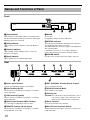
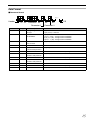
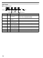
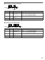
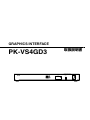
GRAPHICS INTERFACE
INSTRUCTIONS / 取扱説明書
PK-VS4GD3G
PK-VS4GD3
GRAPHICS INTERFACE
Visualization Series
MODE
%
Thank you for purchasing this JVC product.
Please study this instruction manual carefully before
starting to operate the unit, in order to use the unit correctly.
We take no responsibility for any problems resulting from
misuse of this unit by operating this equipment other than
instructed in this manual.
お買い上げありがとうございます。
ご使用の前に、この取扱説明書をお読みのうえ、正しく
お使いください。
本書に記載のない操作によって発生した不具合に対して、
弊社は一切の責任を負いません。
STATUS
&
For Customer use :
Enter below the serial No. which is
located on the rear side of the
cabinet. Retain this information for
future reference.
Model No. PK-VS4GD3G
Serial No.
LCT2540-004A
Safety Precautions
IMPORTANT INFORMATION
WARNING:
TO PREVENT FIRE OR SHOCK HAZARDS, DO NOT
EXPOSE THIS APPLIANCE TO RAIN OR MOISTURE.
WARNING:
THIS APPARATUS MUST BE EARTHED.
CAUTION:
To reduce the risk of electric shock, do not remove
cover. Refer servicing to qualified service personnel.
This product is equipped with a 3-blade grounding type
plug to satisfy FCC rule. If you are unable to insert the
plug into the outlet, contact your electrician.
FCC INFORMATION (U.S.A. only)
CAUTION:
Changes or modification not approved by JVC could
void the user’s authority to operate the equipment.
NOTE:
This equipment has been tested and found to comply
with the limits for a Class A digital device, pursuant to
Part 15 of the FCC Rules. These limits are designed to
provide reasonable protection against harmful
interference when the equipment is operated in a
commercial environment. This equipment generates,
uses, and can radiate radio frequency energy and, if not
installed and used in accordance with the instruction
manual, may cause harmful interference to radio
communications. Operation of this equipment in a
residential area is likely to cause harmful interference in
which case the user will be required to correct the
interference at his own expense.
About the installation place
Do not install this product in a place that cannot support
its weight securely.
If the installation place is not sturdy enough, this product
could fall or overturn, possibly causing personal injury.
2
IMPORTANT SAFEGUARDS
Electrical energy can perform many useful functions. This
unit has been engineered and manufactured to assure
your personal safety. But IMPROPER USE CAN RESULT
IN POTENTIAL ELECTRICAL SHOCK OR FIRE
HAZARD. In order not to defeat the safeguards
incorporated into this product, observe the following basic
rules for its installation, use and service. Please read
these Important Safeguards carefully before use.
- All the safety and operating instructions should be read
before the product is operated.
- The safety and operating instructions should be retained
for future reference.
- All warnings on the product and in the operating
instructions should be adhered to.
- All operating instructions should be followed.
- Place this product near a wall outlet where the plug can
be easily unplugged.
- Unplug this product from the wall outlet before cleaning.
Do not use liquid cleaners or aerosol cleaners. Use a
damp cloth for cleaning.
- Do not use attachments not recommended by the product
manufacturer as they may be hazardous.
- Do not use this product near water. Do not use
immediately after moving from a low temperature to high
temperature, as this causes condensation, which may
result in fire, electric shock, or other hazards.
- Do not place this product on an unstable cart, stand, or
table. The product may fall, causing serious injury to a
child or adult, and serious damage to the product. The
product should be mounted according to the
manufacturer’s instructions, and should use a mount
recommended by the manufacturer.
- When the product is used on a cart,
care should be taken to avoid quick
stops, excessive force, and uneven
surfaces which may cause the product
and cart to overturn, damaging
equipment or causing possible injury to
the operator.
- Slots and openings in the cabinet are
provided for ventilation. These ensure reliable operation of
the product and protect it from overheating. These
openings must not be blocked or covered. (The openings
should never be blocked by placing the product on bed,
sofa, rug, or similar surface. It should not be placed in a
built-in installation such as a bookcase or rack unless
proper ventilation is provided.)
- This product should be operated only with the type of
power source indicated on the label. If you are not sure of
the type of power supply to your home, consult your
product dealer or local power company.
- This product is equipped with a three-wire plug. This plug
will fit only into a grounded power outlet. If you are unable
to insert the plug into the outlet, contact your electrician to
install the proper outlet. Do not defeat the safety purpose
of the grounded plug.
- Power-supply cords should be routed so that they are not
likely to be walked on or pinched by items placed upon or
against them. Pay particular attention to cords at doors,
plugs, receptacles, and the point where they exit from the
product.
- For added protection of this product during a lightning
storm, or when it is left unattended and unused for long
periods of time, unplug it from the wall outlet and
disconnect the cable system. This will prevent damage to
the product due to lightning and power line surges.
- Do not overload wall outlets, extension cords, or
convenience receptacles on other equipment as this can
result in a risk of fire or electric shock.
- Never push objects of any kind into this product through
openings as they may touch dangerous voltage points or
short out parts that could result in a fire or electric shock.
Never spill liquid of any kind on the product.
- Do not attempt to service this product yourself as opening
or removing covers may expose you to dangerous
voltages and other hazards. Refer all service to qualified
service personnel.
- Unplug this product from the wall outlet and refer service
to qualified service personnel under the following
conditions:
a)
b)
c)
d)
When the power supply cord or plug is damaged.
If liquid has been spilled, or objects have fallen on the product.
If the product has been exposed to rain or water.
If the product does not operate normally by following the
operating instructions. Adjust only those controls that are
covered by the Operation Manual, as an improper adjustment
of controls may result in damage and will often require
extensive work by a qualified technician to restore the product
to normal operation.
e) If the product has been dropped or damaged in any way.
f) When the product exhibits a distinct change in performance this indicates a need for service.
POWER CONNECTION
Power cord
Power supply voltage:
AC100 V – 120 V
WARNING:
Do not cut off the main plug from this equipment.
If the plug fitted is not suitable for the power points in
your home or the cable is too short to reach a power
point, then obtain an appropriate safety approved
extension lead or adapter or consult your dealer.
If nonetheless the mains plug is cut off, dispose of the
plug immediately, to avoid a possible shock hazard by
inadvertent connection to the main supply. If a new
main plug has to be fitted, then follow the instruction
given below.
- When replacement parts are required, be sure the service
technician has used replacement parts specified by the
manufacturer or with same characteristics as the original
part. Unauthorized substitutions may result in fire, electric
shock, or other hazards.
- Upon completion of any service or repairs to this product,
ask the service technician to perform safety checks to
determine that the product is in proper operating
condition.
- The product should be placed more than one foot away
from heat sources such as radiators, heat registers,
stoves, and other products (including amplifiers) that
produce heat.
- When connecting other products such as projector, video
source and control PC, you should turn off the power of
this product for protection against electric shock.
- Do not place combustibles behind the cooling fan. For
example, cloth, paper, matches, aerosol cans or gas
lighters that present special hazards when over heated.
- Use only the accessory cord designed for this product to
prevent shock.
- Use only with SPU80-105 for AC Adapter.
*DO NOT allow any unqualified person to install
the unit.
Be sure to ask your dealer to install the unit since
special technical knowledge and skills are required for
installation. If installation is performed by an
unqualified person, it may cause personal injury or
electrical shock.
3
EMC Supplement (Europe only)
- This equipment is in conformity with the provisions and protection requirements of the corresponding European Directives.
This equipment is designed for professional appliances in large scale fixed installations and can be used in the following
environments.
● Controlled EMC environment (for example purpose built broadcasting or recording studio), and the rural outdoors
environment (far away from railways, transmitters, overhead power lines, etc).
In order to keep the best performance and furthermore for electromagnetic compatibility we recommend to use the cables not
exceeding the following length:
Cables
AC power cord
DC power cord
DVI (x8) cable
RS-232C cable
USB cable
LAN cable
Optical cable
Power supply cord
Power supply cord
Shielded cable
Shielded cable
Shielded cable
Shielded cable
Shielded cable
Length
1.8 m
1.8 m
3.0 m
1.8 m
1.8 m
2.0 m
50 m
● The inrush current of this apparatus is 9.5 amperes.
WARNING
This is a Class A product. In a domestic environment this product may cause radio interference in which case the user
may be required to take adequate measures.
In case where the strong electromagnetic waves or magnetism are near the signal cable, the picture will contain noise. In
such cases, please keep the cable away from the sources of the disturbance.
Dear Customer,
This apparatus is in conformance with the valid European directives and standards regarding electromagnetic
compatibility and electrical safety.
European representative of JVC KENWOOD Corporation is:
JVC Technical Services Europe GmbH
Konrad-Adenauer-Allee 1-11
61118 Bad Vilbel
Germany
ENGLISH
Information for Users on Disposal of Old
Equipment
Attention:
This symbol is only
valid in the European
Union.
DEUTSCH
Benutzerinformationen zur Entsorgung alter
Geräte
Hinweis:
Dieses Symbol ist nur
in der Europäischen
Uniongültig.
[European Union]
[Europäische Union]
This symbol indicates that the electrical and electronic equipment should not
be disposed as general household waste at its end-of-life. Instead, the
product should be handed over to the applicable collection point for the
recycling of electrical and electronic equipment for proper treatment, recovery
and recycling in accordance with your national legislation.
By disposing of this product correctly, you will help to conserve natural
resources and will help prevent potential negative effects on the environment
and human health which could otherwise be caused by inappropriate waste
handling of this product. For more information about collection point and
recycling of this product, please contact your local municipal office, your
household waste disposal service or the shop where you purchased the
product.
Penalties may be applicable for incorrect disposal of this waste, in
accordance with national legislation.
Dieses Symbol zeigt an, dass das elektrische bzw. elektronische Gerät nicht als
normaler Haushaltsabfall entsorgt werden soll. Stattdessen sollte das Produkt
zur fachgerechten Entsorgung, Weiterverwendung und Wiederverwertung in
Übereinstimmung mit der Landesgesetzgebung einer entsprechenden
Sammelstelle für das Recycling elektrischer und elektronischer Geräte
zugeführt werden.
Die korrekte Entsorgung dieses Produkts dient dem Umweltschutz und
verhindert mögliche Schäden für die Umwelt und die menschliche Gesundheit,
welche durch unsachgemäße Behandlung des Produkts auftreten können.
Weitere Informationen zu Sammelstellen und dem Recycling dieses Produkts
erhalten Sie bei Ihrer Gemeindeverwaltung, Ihrem örtlichen
Entsorgungsunternehmen oder in dem Geschäft, in dem Sie das Produkt
gekauft haben.
Für die nicht fachgerechte Entsorgung dieses Abfalls können gemäß der
Landesgesetzgebung Strafen ausgesprochen werden.
(Business users)
If you wish to dispose of this product, please visit our web page
www.jvc-europe.com to obtain information about the take-back of the
product.
[Other Countries outside the European Union]
If you wish to dispose of this product, please do so in accordance with
applicable national legislation or other rules in your country for the treatment
of old electrical and electronic equipment.
4
(Geschäftskunden)
Wenn Sie dieses Produkt entsorgen möchten, besuchen Sie bitte unsere
Webseite www.jvc-europe.com, um Informationen zur Rücknahme des
Produkts zu erhalten.
[Andere Länder außerhalb der Europäischen Union]
Wenn Sie dieses Produkt entsorgen möchten, halten Sie sich dabei bitte an
die entsprechenden Landesgesetze und andere Regelungen in Ihrem Land
zur Behandlung elektrischer und elektronischer Geräte.
FRANÇAIS
Informations relatives à l’élimination des
appareils usagés, à l’intention des utilisateurs
Attention:
ESPAÑOL / CASTELLANO
Información para los usuarios sobre la
eliminación de equipos usados
Atención:
Ce symbole n’est
reconnu que dans
l’Union européenne.
Este símbolo sólo es
válido en la Unión
Europea.
[Union européenne]
[Unión Europea]
Lorsque ce symbole figure sur un appareil électrique et électronique, cela
signifie qu’il ne doit pas être éliminé en tant que déchet ménager à la fin de
son cycle de vie. Le produit doit être porté au point de pré-collecte approprié
au recyclage des appareils électriques et électroniques pour y subir un
traitement, une récupération et un recyclage, conformément à la législation
nationale.
En éliminant correctement ce produit, vous contriburez à la conservation des
ressources naturelles et à la prévention des éventuels effets négatifs sur
l’environnement et la santé humaine, pouvant être dus à la manipulation
inappropriée des déchets de ce produit. Pour plus d’informations sur le point
de pré-collecte et le recyclage de ce produit, contactez votre mairie, le
service d’évacuation des ordures ménagères ou le magasin dans lequel vous
avez acheté le produit.
Des amendes peuvent être infligées en cas d’élimination incorrecte de ce
produit, conformément à la législation nationale.
Este símbolo indica que los aparatos eléctricos y electrónicos no deben
desecharse junto con la basura doméstica al final de su vida útil. El producto
deberá llevarse al punto de recogida correspondiente para el reciclaje y el
tratamiento adecuado de equipos eléctricos y electrónicos de conformidad con
la legislación nacional.
Si desecha el producto correctamente, estará contribuyendo a conservar
los recursos naturales y a prevenir los posibles efectos negativos en el
medio ambiente y en la salud de las personas que podría causar el
tratamiento inadecuado del producto desechado. Para obtener más
información sobre el punto de recogida y el reciclaje de este producto,
póngase en contacto con su oficina municipal, su servicio de recogida de
basura doméstica o la tienda en la que haya adquirido el producto.
De acuerdo con la legislación nacional, podrían aplicarse multas por la
eliminación incorrecta de estos desechos.
(Utilisateurs professionnels)
Si desea desechar este producto, visite nuestra página Web
www.jvc-europe.com para obtener información acerca de la retirada del
producto.
Si vous souhaitez éliminer ce produit, visitez notre page Web
www.jvc-europe.com afin d’obtenir des informations sur sa récupération.
[Pays ne faisant pas partie de l’Union européenne]
Si vous souhaitez éliminer ce produit, faites-le conformément à la législation
nationale ou autres règles en vigueur dans votre pays pour le traitement
des appareils électriques et électroniques usagés.
(Empresas)
[Otros países no pertenecientes a la Unión
Europea]
Si desea desechar este producto, hágalo de conformidad con la legislación
nacional vigente u otras normativas de su país para el tratamiento de
equipos eléctricos y electrónicos usados.
NEDERLANDS
Informatie voor gebruikers over het weggooien
van oude apparatuur
Let op:
Dit symbool is alleen
geldig in de
Europese Unie.
ITALIANO
Informazioni per gli utenti sullo smaltimento
delle apparecchiature obsolete
Attenzione:
Questo simbolo è valido
solo nell’Unione Europea.
[Europese Unie]
Deze markering geeft aan dat de elektrische en elektronische apparatuur bij
het einde van de gebruiksduur niet bij het huishoudelijk afval mag worden
gegooid. Het product moet in plaats daarvan worden ingeleverd bij het
relevante inzamelingspunt voor hergebruik van elektrische en elektronische
apparatuur, voor juiste verwerking, terugwinning en hergebruik in
overeenstemming met uw nationale wetgeving.
Door dit product naar het inzamelingspunt te brengen, werkt u mee aan het
behoud van natuurlijke hulpbronnen en met het voorkomen van potentiële
negatieve effecten op het milieu en de volksgezondheid, die anders
veroorzaakt zouden kunnen worden door onjuiste afvalverwerking van dit
product. Neem voor meer informatie over inzamelingspunten en hergebruik
van dit product contact op met de gemeente in uw woonplaats, het
afvalverwerkingsbedrijf of de winkel waar u het product hebt aangeschaft.
Er kunnen boetes gelden voor een onjuiste verwijdering van dit afval, in
overeenstemming met de nationale wetgeving.
[Unione Europea]
(Zakelijke gebruikers)
(Per gli utenti aziendali)
Bezoek als u dit product wilt weggooien onze website
www.jvc-europe.com voor informatie over het terugnemen van het product.
[Landen buiten de Europese Unie]
Wanneer u dit product wilt verwijderen, houdt u dan aan de geldende
nationale wetgeving of andere regels in uw land voor de verwerking van
oude elektrische en elektronische apparatuur.
Questo simbolo indica che l’apparecchiatura elettrica ed elettronica a cui è
relativo non deve essere smaltita tra i rifiuti domestici generici alla fine della sua
vita utile. Il prodotto, invece, va consegnato a un punto di raccolta appropriato
per il riciclaggio di apparecchiature elettriche ed elettroniche, per il trattamento,
il recupero e il riciclaggio corretti, in conformità alle proprie normative nazionali.
Mediante lo smaltimento corretto di questo prodotto, si contribuirà a preservare
le risorse naturali e a prevenire potenziali effetti negativi sull’ambiente e sulla
salute umana che potrebbero essere provocati, altrimenti, da uno smaltimento
inappropriato del prodotto. Per ulteriori informazioni sul punto di raccolta e il
riciclaggio di questo prodotto, contattare la sede comunale locale, il servizio di
smaltimento rifiuti domestici o il negozio in cui si è acquistato il prodotto.
L’utente è responsabile del conferimento dell’apparecchio a fina vita alle
appropriate strutture di raccolta, pena le sanzioni previste dalla vigente
legislazione sui rifiuti.
Qualora si desideri smaltire questo prodotto, visitare la nostra pagina web
www.jvc-europe.com per ottenere informazioni sul ritiro del prodotto.
[Per altre nazioni al di fuori dell’Unione Europea]
Qualora si desideri smaltire questo prodotto, effettuare lo smaltimento in
conformità alla normativa nazionale applicabile o alle altre leggi della
propria nazione relative al trattamento delle apparecchiature elettriche ed
elettroniche obsolete.
5
PORTUGUÊS
Informações para os Utilizadores sobre a
Eliminação de Equipamento Antigo
DANSK
Brugerinformation om bortskaffelse af gammelt
udstyr
Atenção:
Bemærk:
Este símbolo apenas é
válido na União Europeia.
Dette symbol er kun gyldigt
i EU.
[União Europeia]
[EU]
Este símbolo indica que o equipamento eléctrico e electrónico não deve ser
eliminado como um resíduo doméstico geral, no fim da respectiva vida útil.
Pelo contrário, o produto deve ser entregue num ponto de recolha
apropriado, para efectuar a reciclagem de equipamento eléctrico e
electrónico e aplicar o tratamento, recuperação e reciclagem adequados,
de acordo com a respectiva legislação nacional.
Ao eliminar este produto da forma correcta, ajudará a conservar recursos
naturais e ajudará a evitar potenciais efeitos negativos no ambiente e
saúde humana, que poderiam ser causados pelo tratamento residual
inadequado deste produto. Para mais informações sobre o ponto de
recolha e reciclagem deste produto, contacte a respectiva entidade local, o
serviço de eliminação de resíduos ou a loja onde adquiriu o produto.
Caso estes resíduos não sejam correctamente eliminados, poderão ser
aplicadas penalizações, em conformidade com a respectiva legislação
nacional.
Elektriske produkter og elektroniske apparater med dette symbol må ikke
afhændes på samme måde som almindeligt husholdningsaffald, når det
skal smides ud. I stedet skal produktet indleveres på det relevante
indsamlingssted for elektriske apparater og elektronisk udstyr, hvor det vil
blive håndteret korrekt og efterfølgende genanvendt og recirkuleret i
henhold til de love, der gælder i dit land.
Ved at bortskaffe dette produkt korrekt, medvirker du til at bevare naturens
ressourcer samt forhindre eventuelle negative påvirkninger af miljøet og
folkesundheden, der ellers kunne forårsages ved forkert affaldshåndtering
af dette produkt. Mere information om indsamlingssteder og genanvendelse
af dette produkt kan du få ved at kontakte din lokale kommune, dit
renovationsselskab eller den forretning, hvor du har købt produktet.
Ukorrekt bortskaffelse af dette affald kan være strafbar ifølge lovgivningen i
nogle lande.
(utilizadores profissionais)
Hvis du ønsker at bortskaffe dette produkt, kan du på vores webside
www.jvc-europe.com få information om tilbagetagning af produktet.
Se pretender eliminar este produto, visite a nossa página da web em
www.jvc-europe.com para obter informações sobre a devolução do produto.
[Outros países fora da União Europeia]
Se pretender eliminar este produto, faça-o de acordo com a legislação
nacional aplicável ou outras regras no seu país para o tratamento de
equipamento eléctrico e electrónico velho.
(Professionelle brugere)
[Lande uden for EU]
Hvis du ønsker at bortskaffe dette produkt, bedes du gøre det i
overensstemmelse med gældende lovgivning eller andre regler i dit land for
behandling af gammelt elektrisk og elektronisk udstyr.
ΕΛΛΗΝΙΚΑ
Πληροφορίες σχετικά µε την απόρριψη
εξοπλισµού
Προσοχή:
Αυτή η σήµανση ισχύει
µόνο για την Ευρωπαϊκή
Ένωση.
[Ευρωπαϊκή Ένωση]
Αυτή η σήµανση υποδηλώνει ότι ο ηλεκτρικός και ηλεκτρονικός εξοπλισµός
δεν πρέπει να απορριφθεί ως κοινό οικιακό απόρριµµα. Αντ' αυτού, το
προϊόν πρέπει να παραδοθεί στο ανάλογο σηµείο περισυλλογής για την
ανακύκλωση των ηλεκτρικών και ηλεκτρονικών µερών και την κατάλληλη
επεξεργασία, σύµφωνα µε τη νοµοθεσία της χώρας σας.
Η σωστή απόρριψη αυτού το προϊόντος βοηθάει στη διαφύλαξη των
φυσικών πόρων και στην αποφυγή αρνητικών επιπτώσεων στο περιβάλλον
και στην ανθρώπινη υγεία, κάτι που ενδέχεται να προκληθεί από την
ακατάλληλη διαχείριση αυτού του προϊόντος ως απόρριµµα. Για
περισσότερες πληροφορίες σχετικά µε τα σηµεία περισυλλογής και
ανακύκλωσης αυτού του προϊόντος, επικοινωνήστε µε τα γραφεία της
τοπικής αυτοδιοίκησης, την υπηρεσία περισυλλογής απορριµµάτων ή το
κατάστηµα από το οποίο αγοράσατε το προϊόν.
Ανάλογα µε τη νοµοθεσία της χώρας σας, ενδέχεται να επιβληθούν
κυρώσεις σε περίπτωση λανθασµένης απόρριψης αυτού του προϊόντος.
(Επιχειρήσεις)
Αν επιθυµείτε να απορρίψετε αυτό το προϊόν, επισκεφτείτε το διαδικτυακό
µας τόπο www.jvc-europe.com για περισσότερες πληροφορίες σχετικά µε
την επιστροφή του προϊόντος.
[Άλλες χώρες εκτός Ευρωπαϊκής Ένωσης]
Αν επιθυµείτε να απορρίψετε αυτό το προϊόν, πρέπει να τηρήσετε την
ισχύουσα εθνική νοµοθεσία ή όποιους άλλους κανονισµούς για τη χώρα
σας για την απόρριψη ηλεκτρικού και ηλεκτρονικού εξοπλισµού.
6
SUOMI
Tietoja käyttäjille vanhojen laitteiden
hävittämisestä
Huomio:
Tämä symboli on voimassa
vain Euroopan unionissa.
[Euroopan unioni]
Tämä symboli tarkoittaa, että sähkö- ja elektroniikkalaitteita ei tule laittaa
talousjätteisiin, kun ne poistetaan käytöstä. Sen sijaan tuotteet tulee
toimittaa asianmukaiseen sähkö- ja elektroniikkalaitteiden
kierrätyspisteeseen, jossa ne käsitellään uusiokäyttöä ja kierrätystä varten
paikallisen lainsäädännön mukaan.
Kun hävität tuotteen asianmukaisella tavalla, autat säästämään
luonnonvaroja ja estämään mahdollisia ympäristö- ja terveyshaittoja, joita
voisi aiheutua tämän tuotteen vääränlaisesta hävittämisestä. Lisätietoja
keräyspisteistä ja tämän tuotteen kierrätyksestä saat paikkakuntasi
viranomaisilta, kotitalousjätteiden keräyksestä huolehtivasta yrityksestä tai
liikkeestä, josta ostit tuotteen.
Tuotteen vääränlaisesta hävittämisestä voi seurata paikallisen
lainsäädännön mukaisia rangaistuksia.
(Yrityskäyttäjät)
Jos haluat hävittää tämän tuotteen, web-sivustoltamme osoitteessa
www.jvc-europe.com löydät tietoja käytetyn tuotteen palautuksesta.
[Muut maat Euroopan unionin ulkopuolella]
Jos haluat hävittää tämän tuotteen, tee se kansallisen lainsäädännön tai
muiden maassasi voimassa olevien määräysten mukaan, jotka koskevat
vanhojen sähkö- ja elektroniikkalaitteiden käsittelyä.
РУССКИЙ
SVENSKA
Information till användare gällande kassering av
gammal utrustning
Информация для пользователей,
выбрасывающих старое оборудование
Tänk på:
Внимание:
Att denna symbol endast
gäller inom den
Europeiska gemenskapen.
Действие этого символа
распространяется только
на Европейский Союз.
[Europeiska gemenskapen]
[Европейский Союз]
Denna symbol anger att elektrisk och elektronisk utrustning inte ska
kasseras som vanligt hushållsavfall, när de inte ska användas mer. Istället
ska produkten lämnas in på lämplig återvinningsstation för elektrisk eller
elektronisk utrustning, så att den kan tas om hand och återvinnas i enlighet
med ert lands lagstiftning.
Genom att avyttra denna profukt på rätt sätt, bidrar du till att bevara naturen
och förhindrar potentiellt negativa effekter på miljön och den mänskiliga
hälsan, som annars kan bli resultatet vid felaktig hantering av denna
produkt. Kontakta ditt kommunkontor, det företag som hanterar dina
hushållssopor eller butiken där du köpt produkten, för mer information om
återvinningscentraler.
Det kan hända att du bötfälls i enlighet med ert lands lagstiftning om detta
avfall kasseras på fel sätt.
Это символ указывает, что после окончания срока службы
соответствующего электрического или электронного оборудования,
нельзя выбрасывать его вместе с обычным бытовым мусором. Вместо
этого, оно подлежит сдаче на утилизацию в соответствующий пункт
приема электрического и электронного оборудования для
последующей переработки и утилизации в соответствии с
национальным законодательством.
Обеспечивая правильную утилизацию данного продукта, Вы
помогаете сберечь природные ресурсы и предотвращаете ущерб для
окружающей среды и здоровья людей, который возможен в случае
ненадлежащего обращения. Более подробную информацию о пунктах
приема и утилизации данного продукта можно получить в местных
муниципальных органах, на предприятии по вывозу бытового мусора
или по месту приобретения продукта.
Нарушение правил утилизации данного типа отходов в соответствии с
национальным законодательством является административным
правонарушением.
(Företagsanvändare)
Om ni vill kassera denna produkt, besök vår webbsida
www.jvc-europe.com för att få information om returnering av produkten.
[Övriga länder utanför den Europeiska
gemenskapen]
Om du vill kassera denna produkt, ska detta göras i enlighet med gällande
lagstiftning i landet, eller enligt andra bestämmelser i ditt land, för
behandling av gammal elektrisk eller elektronisk utrustning.
NORSK
Informasjon til brukerne om kassering av
gammelt utstyr
(Организации-пользователи)
Прежде чем выбрасывать данный продукт, ознакомьтесь с
информацией о приемке отработавших продуктов, приведенной на
веб-узле www.jvc-europe.com.
[Страны, не входящие в Европейский Союз]
Если Вы собираетесь выбросить данный продукт, руководствуйтесь
национальным законодательством или другими правилами,
действующими в Вашей стране по отношению к переработке старого
электрического и электронного оборудования.
ČESKY
OBS!
Dette symbolet er kun gyldig
i den Europeiske Union og i
EFTA-landene Norge, Island
og Sveits.
[Europeiske Union]
Dette symbolet betyr at det elektriske eller elektroniske utstyret ikke skal
kasseres som vanlig husholdningsavfall når det har nådd slutten av sin
levetid. I stedet skal produktet leveres til en passende mottaksstasjon for
kasserte elektriske og elektroniske produkter, slik at disse kan behandles,
gjenvinnes og resirkuleres i samsvar med nasjonal lovgivning.
Hvis du kasserer dette produktet på riktig måte, bidrar til du til å bevare
naturlige ressurser og til å motvirke de negative virkningene på miljøet og
den menneskelige helse som kan oppstå hvis produktet kasseres på feil
måte. Hvis du vil ha mer informasjon om mottaksstasjoner og gjennvinning
av dette produktet, kan du ta kontakt med kommunen din,
renovasjosselskapet ditt eller den forhandleren du kjøpte produktet av.
Feilaktig kassering av dette utstyret kan kanskje bøtelegges, avhengig av
nasjonale lover og regler.
(Bedriftsbrukere)
Hvis du ønsker å kassere dette produktet, kan du gå til hjemmesiden vår på
www.jvc-europe.com eller www.elretur.no for å få informasjon om retur av
dette produktet.
[Andre land utenfor EU]
Hvis du ønsker å kassere dette produktet, må du gjøre det i samsvar med
gjeldende nasjonal lovgivning eller andre regler som gjelder i landet ditt når
det gjelder behandling av gammelt elektrisk og elektronisk utstyr.
Informace pro uživatele k likvidaci starého
zařízení
Upozornění:
Tento symbol je platný
jen v Evropské unii.
[Evropská unie]
Tento symbol udává, že elektrické a elektronické vybavení nesmí
být po skončení životnosti likvidován jako běžný komunální odpad.
Produkt musí být předán na příslušném sběrném místě k
správnému zpracování, regeneraci a recyklaci elektrického a
elektronického vybavení. Musí být zlikvidován správně v souladu s
národními předpisy vaší země.
Správnou likvidací tohoto produktu pomůžete zachovat přírodní
zdroje a napomáháte prevenci potenciálních negativních dopadů
na životní prostředí a lidské zdraví, což by mohly být důsledky
nesprávné likvidace tohoto produktu. Podrobnější informace o
sběrném místě a recyklaci tohoto produktu si vyžádejte od
místních úřadů, podniku zabývajícího se likvidací komunálních
odpadů ve vašem místě nebo obchodu, kde jste produkt zakoupili.
Nesprávná likvidace tohoto odpadu může mít za následek postih
podle národní legislativy.
(Firemní uživatelé)
Přejete-li si tento produkt zlikvidovat, navštivte prosím naši
webovou stránku www.jvc-europe.com, kde získáte informace o
možnosti vrácení produktu.
[Ostatní země mimo Evropskou unii]
Přejete-li si zlikvidovat tento produkt, proveďte to prosím v
souladu s příslušnými národními zákony nebo jinými předpisy
platnými ve vaší zemi, které se vztahují k likvidaci starého
elektrického a elektronického vybavení.
7
POLSKI
Informacja dla użytkowników, dotycząca
utylizacji niesprawnych urządzeń
Uwaga:
Informacija za korisnike gde da odlazu staru
opremul
[Vazece sa se zemlje koje su usvojile
skupljanje razlicitod odpada systems]
Taki symbol jest ważny
tylko w Unii Europejskej.
[Kraje Unii Europejskiej]
Symbol przedstawiony obok oznacza, że urządzeń elektrycznych i
elektronicznych po zakończeniu okresu ich eksploatacji nie należy
wyrzucać razem z odpadami gospodarczymi. Należy je natomiast
przekazać do punktu odbioru urządzeń elektrycznych i
elektronicznych w celu ich odpowiedniego przerobu, odzysku i
utylizacji zgodnie z krajowym ustawodawstwem.
Dbając o prawidłową utylizację produktu, przyczyniasz się do
ochrony zasobów naturalnych i zmniejszasz negatywny wpływ
oddziaływania na środowisko i zdrowie ludzi, zagrożone
niewłaściwym traktowaniem odpadów elektronicznych. Szczegółowe
informacje dotyczące punktów zbiórki i powtórnego przerobu
odpadów można uzyskać u władz lokalnych, w firmach zajmujących
się zagospodarowaniem odpadów lub w sklepie z artykułami
elektronicznymi.
Zgodnie z krajowym ustawodawstwem w przypadku
nieprawidłowego usuwania wspomnianych odpadów mogą być
nakładane kary.
(Użytkownicy biznesowi)
Jeśli zaszła potrzeba pozbycia się niniejszego produktu, prosimy
zajrzeć na strony www.jvc-europe.com, aby uzyskać informacje o
możliwości jego odbioru.
[Kraje poza Unią Europejską]
W razie konieczności pozbycia się niniejszego produktu prosimy
postępować zgodnie z lokalnymi przepisami lub innymi zasadami
postępowania ze zużytym sprzętem elektrycznymi i elektronicznymi.
MAGYAR
Felhasználói tájékoztató az elhasznált
berendezések ártalmatlanításáról
Figyelem!
Ez a szimbólum csak az
Európai Unióban
érvényes.
[Európai Unió]
Ez a szimbólum azt jelzi, hogy az elektromos és elektronikus
berendezést a hasznos élettartama végén nem szabad háztartási
szemétként kezelni. Ehelyett a terméket a megfelelő, elektromos és
elektronikus berendezések hulladékainak hasznosítására szakosodott
gyűjtőhelyre kell vinni, hogy a nemzeti törvényeknek megfelelően
történjék kezelése, visszanyerése és újrahasznosítása.
A termék megfelelő ártalmatlanításával segít megőrizni a természetes
erőforrásokat és megelőzheti azokat a környezetre és az egészségre
gyakorolt ártalmas hatásokat, amelyeket a termék hulladékának
helytelen kezelése egyébként okozhat, továbbá csökkenti az
elektromos berendezésekből származó hulladékok mennyiségét és
segíti az újrahasznosítást és újrafeldolgozást.
A nemzeti törvények értelmében az ilyen hulladék helytelen
ártalmatlanítása esetén büntetést szabhatnak ki.
(Üzleti felhasználók)
Amennyiben ártalmatlanítani kívánja ezt a terméket, kérjük,
látogasson el weboldalunkra: www.jvc-europe.com, ahol
tájékoztatást kaphat a termék visszavételével kapcsolatban.
[Az Európai Unión kívüli országok]
Amennyiben ártalmatlanítani kívánja ezt a terméket, kérjük, a
megfelelő nemzeti jogszabályok, illetve az Ön országának az
elektromos és elektronikus berendezések hulladékának
kezelésére vonatkozó, egyéb szabályai szerint végezze.
8
Српска
Ovi simboli znace da svaki uredjaj sa ovim simbolom ne bi
trebalo da ostaju kao otpad u domacinstvu kada se istrosi.
Umesto toga uredjaj treba da se preda na vazecim mestima
gde se skuplja odpad za reciklazu elektricne I elektronske
opreme za odgovarajuci tretman u skladu sa vasim zakonom
Odlaganje ovih proizvoda ispravno, vi cete pomoci da se
sprece negativne posledice na zivotnu sredinu I ljudsko
zdralje koje bi inace moglo biti prouzrokovano neprikladnim
rukovanjem ovim uredjajem
Za vise informacija omestima za skuoljanje uredjaju za
reciklazu I reciklazu navedenih proizvoda kontaktirajte
kontaktirajte lokalnu kancelariju, ili serviskoji skuplja vas
odpad da odkupi uredjaj od prodavnice
Ako koristite uredjaj kojiima u sebi baterije, akomulator,
molim vas odlozite ih odvojeno unapred prema lokalnim
zahtevima
(Biznis korisnici)
Ako zelite da odlozite svoj uredjaj, molim vas kontaktirajte vaseg
prodavca ili isporucioca za dalje informacije
Contents
Safety Precautions . . . . . . . . . . . . . . . . . . .2
Contents . . . . . . . . . . . . . . . . . . . . . . . . . . .9
Accessories . . . . . . . . . . . . . . . . . . . . . . . . .9
Names and Functions of Parts . . . . . . . . .10
Front . . . . . . . . . . . . . . . . . . . . . . . . . . .10
Rear . . . . . . . . . . . . . . . . . . . . . . . . . . .10
Connecting . . . . . . . . . . . . . . . . . . . . . . . .11
Connecting to a Device . . . . . . . . . . . . .11
Turning on the Power . . . . . . . . . . . . . . . . .13
Mounting the Rack . . . . . . . . . . . . . . . . . . .13
External Control . . . . . . . . . . . . . . . . . . . . .14
RS232C Specifications . . . . . . . . . . . . .14
TCP/IP Connection . . . . . . . . . . . . . . . .14
Data Format . . . . . . . . . . . . . . . . . . . . .15
Tally Format . . . . . . . . . . . . . . . . . . . . . .16
Header . . . . . . . . . . . . . . . . . . . . . . . . .18
ID . . . . . . . . . . . . . . . . . . . . . . . . . . . . . .18
CR . . . . . . . . . . . . . . . . . . . . . . . . . . . . .18
Error Code . . . . . . . . . . . . . . . . . . . . . . .18
Command (Detail) . . . . . . . . . . . . . . . . .19
Specifications . . . . . . . . . . . . . . . . . . . . . .26
Dimensions . . . . . . . . . . . . . . . . . . . . . . . .27
Accessories
䡵 AC Adapter
(1.8 m)
䡵 Power Cord
(1.8 m)
䡵 Rack Mounting Brackets (2 pieces)
䡵 Bracket Mounting Screws
(M4x10mm, 4 pieces)
䡵 Instructions Manual
䡵 Warranty Card
9
Names and Functions of Parts
Front
AC
BD
GRAPHICS INTERFACE
Visualization Series
%
MODE
STATUS
E
F
&
G
A [Opt] Indicator
E MODE
Lights up when an optical fiber cable is connected between
the optical transmitter and optical receiver units, and appears
blinking if cable is not connected.
Do not open.
Changing the settings will cause malfunction.
F STATUS Indicator
B [Sink] Indicator
This unit performs initialization when the power is turned on.
The initialization takes about 15 seconds.
The STATUS indicator shows the progress of the initialization
with a dotted number.
If the indicator shows "0." to "8." in order and finally "1"
(factory default unit ID), the unit is in working condition.
Lights up when a monitor display is connected. (Monitors
HPD)
C [Source] Indicator
Lights up when a video signal generator is connected.
(Monitors +5 V supply)
G POWER Switch
D [Dual] Indicator
Use this to turn on/off the main power supply of this unit.
Lights up when there is a dual-link signal input.
Rear
H
DC IN 12V
I
J
K
USB
LAN
DVI 1 OUT
O
P
L
M
REMOTE
OPT
DVI 2 OUT
N
EXT. CONTROL
DVI 3 OUT
SYNC
IN
DVI 4 OUT
Q
H Power Input Terminal
M EXT. CONTROL Terminal (D-sub 15 pins)
Connect the supplied AC adapter to this terminal.
This is an extension terminal.
I LAN Terminal (RJ-45)
N SYNC IN Terminal (BNC)
This unit can be controlled by connecting it to a computer
using a LAN cable.
Input terminal for sync signals.
J USB Terminal (Type B)
O Cooling Fan
This unit can be controlled by connecting it to a computer
using a USB cable.
CAUTION: Do not block the cooling fan with papers, cloth or
soft cushions. Doing so may cause heat to trap
inside the unit and result in fire or malfunction.
K Optical Input Terminal (MPO 12-fiber)
P Earth Terminal
For connecting a 12-fiber MPO connector cable.
Connect the earth wire to this terminal.
L REMOTE Terminal (D-sub 9 pins)
Q DVI OUT to 4 Terminals (DVI-D)
This unit can be controlled by connecting it to a computer
using a RS-232C cross cable.
Output terminal for video signals. Connect it to the projector
using a DVI cable.
10
Connecting
Connecting to a Device
Connect the device in the way as shown in the connection example below.
Do not turn on the power until all connections are made.
For details on the devices that can be connected to this unit, connection method and operation, please consult your authorized
dealer.
Refer to page 13 when mounting the rack.
䡵 When connecting to Projector (DLA-VS2200/DLA-VS2000)
To DVI terminal
DVI-D cable (sold separately)
Transmitter Unit (PK-EXT40TG)
(sold separately)
Video source
OPT
3
1
DVI-D
(Dual link)
100
l
240
VAC
4
2
Optical Fiber Cable
EF-FC1150G
(sold separately)
Computer
RS-232C cross cable
or LAN, USB Cable
(sold separately)
To RS-232C or LAN,
USB terminal *
DC IN 12V
USB
LAN
DVI 1 OUT
REMOTE
OPT
DVI 2 OUT
EXT. CONTROL
DVI 3 OUT
SYNC
IN
DVI 4 OUT
To HDMI terminal
HDMI-DVI conversion cable (sold separately)
Projector (DLA-VS2200/DLA-VS2000) Max 4 units
* To control using the computer, connect to any one of the terminals (RS-232C, LAN or USB). Do not use the terminals at the
same time.
11
䡵 When connecting to DLA-VS4800 (or DLA-SH7, DLA-SH4K)
To DVI terminal
DVI-D cable (sold separately)
Transmitter Unit (PK-EXT40TG)
(sold separately)
Video source
Computer
100
l
OPT
3
1
DVI-D
(Dual link)
240
VAC
4
2
RS-232C cross cable
or LAN, USB Cable
(sold separately)
Optical Fiber Cable
EF-FC1150G
(sold separately)
To RS-232C or LAN,
USB terminal *
DC IN 12V
USB
LAN
DVI 1 OUT
REMOTE
OPT
DVI 2 OUT
EXT. CONTROL
DVI 3 OUT
SYNC
IN
DVI 4 OUT
To DVI terminal
DVI-D cable (sold separately)
DLA-VS4800 (or DLA-SH7, DLA-SH4K)
* To control using the computer, connect to any one of the terminals (RS-232C, LAN or USB). Do not use the terminals at the
same time.
12
Turning on the Power
A Connect the power cord to the AC adapter
Mounting the Rack
You can mount this unit on the EIA 1U rack using the
supplied rack mounting brackets.
A Mount the rack mounting brackets on this
unit using the four supplied bracket
mounting screws
M4 × 10
B Connect the AC adapter to this unit
B Mount this unit on the rack
● The rack mounting screws are not supplied.
C Insert plug into the power outlet
D Turn on the power switch
13
External Control
It is possible to control this unit by connecting it to a PC using an RS232C cross cable (Dsub 9pin).
The projector can be controlled by connecting it to a PC through the computer network with a LAN cable for control commands to
be sent to the projector.
● To control using the computer, connect to any one of the terminals (RS-232C, LAN or USB). Do not use the terminals at the
same time.
● Please use it after you have gained proper understanding from professional books or consulting the system administrator.
RS232C Specifications
Pin No.
This Unit
1
5
6
9
Signal
Function
Signal Direction
2
RxD
Receive data
PC B This unit
3
TxD
Transmission data
This unit B PC
5
GND
Signal ground
—
1, 4, 6-9
N/C
—
—
● PC refers to the controller, such as a personal computer.
D0 D1 D2 D3 D4 D5 D6 D7
Start bit
Stop bit
Mode
Asynchronous
Data bit
8 bit
Parity
None
Start bit
1
Stop bit
1
Data rate
19200 bps
Flow control
None
TCP/IP Connection
Before controlling via LAN, it is necessary to establish connection of the TCP layer by a “3way handshake”, followed by sending
out “PJREQ” and receiving “PJACK” within five seconds after the projector sends out “PJ_OK” for connection authentication.
If you are unable to complete sending within five seconds, or when “PJ_NG” or “PJNAK” is received, check the operating status of
the projector, followed by performing the steps again starting from establishment of a TCP connection,
Within 5 Seconds
Projector
PJ_OK
PJACK
Establishment of TCP Connection
TCP Port No. 20554
3-way Handshake
Projector Control
PJREQ
Controlling PC
Connection Authentication Procedure
14
Data Format
䡵 Command format
I
Header
ID SP Command SP
Parameter 1
Item
SP
CR
SP
Parameter 2
Length
Description
Header
1
The beginning of data and
data type
‘!’ (21) : Command to set or control
‘?’ (3F): Query command
ID
1
Identification number of
PK-VS4GD3G.
‘0’ (30)
‘1’ (31) to ‘9’ (39)
‘A’ (41) to ‘F’ (46)
‘a’ (61) to ‘ f ’ (66)
SP
1
Separation between ID
and command
‘ ’ (20): Separation
Command
n
Command
‘Ixx’: Command code
SP
1
Separation between
command and parameter
‘ ’ (20): Separation
Parameter
Parameter is set from none to “n” depending on the command.
Parameter 1
Note
:
:
:
:
All connected PK-VS4GD3G
Designated PK-VS4GD3G
Designated PK-VS4GD3G
Designated PK-VS4GD3G
SP
1
Separation between
parameter and parameter
‘ ’ (20): Separation
Parameter 2
n
Parameter
Parameter is set from none to “n” depending on the command.
SP
1
Separation between
parameter and parameter
‘ ’ (20): Separation
Parameter n
n
Parameter
Parameter is set from none to “n” depending on the command.
CR
1
End of command
(0D): Indicates the end of data.
···
15
Tally Format
䡵 Tally (response) format
Header
ID SP
SP
Status
Item
Length
SP
Parameter 1
SP
CR
Parameter 2
Description
Note
Header
1
The beginning of tally
‘@’ (40): Response to query
ID
1
Identification number of
PK-VS4GD3G.
‘0’ (30)
: All connected PK-VS4GD3G
‘1’ (31) to ‘9’ (39) : Designated PK-VS4GD3G
‘A’ (41) to ‘F’ (46) : Designated PK-VS4GD3G
SP
1
Separation between ID
and status
‘ ’ (20): Separation
Status
1
Normal termination status
‘0’ (30): Normal termination status code
SP
1
Separation between
status and parameter
‘ ’ (20): Separation
Parameter
Parameter is set from none to “n” depending on the Error.
Parameter 1
SP
1
Separation between
parameter and parameter
‘ ’ (20): Separation
Parameter 2
n
Parameter
Parameter is set from none to “n” depending on the Error.
SP
1
Separation between
parameter and parameter
‘ ’ (20): Separation
···
Parameter n
n
Parameter
Parameter is set from none to “n” depending on the Error.
CR
1
End of tally
(0D): Indicates the end of data.
16
䡵 Tally (Response with normal termination)
Header
CR
ID SP
Status
Item
Length
Description
Note
Header
1
The beginning of tally
‘@’ (40): Response to command
ID
1
Identification number of
PK-VS4GD3G.
‘0’ (30)
: All connected PK-VS4GD3G
‘1’ (31) to ‘9’ (39) : Designated PK-VS4GD3G
‘A’ (41) to ‘F’ (46) : Designated PK-VS4GD3G
SP
1
Separation between ID
and status
‘ ’ (20): Separation
Status
1
Normal termination status
‘0’ (30): Normal termination status code
CR
1
End of tally
(0D): Indicates the end of data.
䡵 Tally (Response with abnormal end)
A
Header
Item
ID SP
Length
Status
CR
Description
Note
Header
1
The beginning of tally
‘@’ (40): Response to command
ID
1
Identification number of
PK-VS4GD3G.
‘0’ (30)
: All connected PK-VS4GD3G
‘1’ (31) to ‘9’ (39) : Designated PK-VS4GD3G
‘A’ (41) to ‘F’ (46) : Designated PK-VS4GD3G
SP
1
Separation between ID
and staus
‘ ’ (20): Separation
Status
1
Abnormal end status
‘Axx’ : Error Code
CR
1
End of tally
(0D): Indicates the end of data.
17
Header
Indicates the beginning and type of communication data.
䡵 Computer N PK-VS4GD3G (Graphics Interface)
Character
Hex
Definition
‘!’
21
Command to the PK-VS4GD3G (Graphics Interface)
‘?’
3F
Query (request for information) to PK-VS4GD3G (Graphics Interface)
䡵 PK-VS4GD3G (Graphics Interface) N Computer
Character
Hex
‘@’
40
Definition
Tally (Response) data
ID
The following numeric characters are used to identify PK-VS4GD3G (Graphics Interface) when two or more PK-VS4GD3G units
are connected to a single computer.
Setting separate identification numbers for each PK-VS4GD3G allows independent control of each PK-VS4GD3G unit.
䡵 Assignable ID numbers
ID
Character (Hex)
ID
Character (Hex)
0
‘0’ (30H)
8
‘8’ (38H)
1
‘1’ (31H)
9
‘9’ (39H)
2
‘2’ (32H)
10
‘A’ (41H) or ‘a’ (61H)
3
‘3’ (33H)
11
‘B’ (42H) or ‘b’ (62H)
4
‘4’ (34H)
12
‘C’ (43H) or ‘c’ (63H)
5
‘5’ (35H)
13
‘D’ (44H) or ‘d’ (64H)
6
‘6’ (36H)
14
‘E’ (45H) or ‘e’ (65H)
7
‘7’ (37H)
15
‘F’ (46H) or ‘ f ’ (66H)
(*) Factory default ID setting is ‘1’ (31H).
ID number ‘0’ (30H) should be used when assigning all connected PK-VS4GD3G units for batch operations. This means that
when assigning independent ID numbers to multiple units, 15 of the 16 assignable numbers (from ‘1’ through ‘F’) can actually be
used for registration.
Please note that tally (response) data is not returned from the PK-VS4GD3G when the global ID assignment function (0) is used.
CR
Indicates the end of each of data. (0DH)
Error Code
Error code
HEX
‘A00’
41 30 30
The command is not supported.
‘A01’
41 30 31
The parameter is invalid, or connection is time out.
‘A02’
41 30 32
The parameter is out of range.
‘A03’
41 30 33
Other errors
‘A04’
41 30 34
Invalid command at the current mode or setting.
‘A05’
41 30 35
The command is invalid when no signal.
‘A06’
41 30 36
The command is under process.
18
Meaning
Command (Detail)
This section describes the commands that can be used with PK-VS4GD3G, Graphics Interface.
䡵 Offset Red: ‘I55’
Function
Command
Parameter
Tally
Sets the red offset to on/off and specifies the offset value if it is on.
‘!’ ‘1’ SP ‘I55’ SP ‘1’ SP ‘1’ SP ‘1234’ CR
‘?’ ‘1’ SP ‘I55’ SP ‘1’ CR
Parameter 1
Specifies the channel number.
‘1’, ‘2’, ‘3’, ‘4’ : Channel number 1, 2, 3, 4
‘0’
: All channels (Not available in a query command.)
Parameter 2
Sets the red offset to On/Off.
‘1’ : On
‘0’ : OFF
Parameter 3
Specifies the offset value if the Parameter 2 is On.
Offset value range: ‘–2048’ to ‘2047’
Normal
‘@’ ‘1’ SP ‘0’ CR
Abnormal
‘@’ ‘1’ SP ‘Axx’ CR
Query
‘@’ ‘1’ SP ‘0’ SP ‘1’ SP ‘1234’ CR
[1] Normal communication
To set the red offset to On and set the offset value to ‘1234’ on the unit ID ‘1’.
‘!’ ‘1’ SP ‘I55’ SP ‘1’ SP ‘1’ SP ‘1234’ CR
‘@’ ‘1’ SP ‘0’ CR
To set the red offset to On and set the offset value to ‘1234’ on all the channels of the unit ID ‘1’.
‘!’ ‘1’ SP ‘I55’ SP ‘0’ SP ‘1’ SP ‘1234’ CR
‘@’ ‘1’ SP ‘0’ CR
Communication
example
[2] Error communication
To set the red offset to On and set the offset value to ‘1234’ on the unit ID ‘1’.
(Refer to the Error code section about ‘Axx’.)
‘!’ ‘1’ SP ‘I55’ SP ‘1’ SP ‘1’ SP ‘1234’ CR
‘@’ ‘1’ SP ‘Axx’ CR
[3] Query communication
To query the red offset setting information of the channel number ‘1’ of the unit ID ‘1’.
‘?’ ‘1’ SP ‘I55’ SP ‘1’ CR
‘@’ ‘1’ SP ‘0’ SP ‘1’ SP ‘1’ SP ‘1234’ CR
19
䡵 Offset Green: ‘I56’
Function
Command
Parameter
Tally
Sets the green offset to on/off and specifies the offset value if it is on.
‘!’ ‘1’ SP ‘I56’ SP ‘1’ SP ‘1’ SP ‘1234’ CR
‘?’ ‘1’ SP ‘I56’ SP ‘1’ CR
Parameter 1
Specifies the channel number.
‘1’, ‘2’, ‘3’, ‘4’ : Channel number 1, 2, 3, 4
‘0’
: All channels (Not available in a query command.)
Parameter 2
Sets the red offset to On/Off.
‘1’ : On
‘0’ : OFF
Parameter 3
Specifies the offset value if the Parameter 2 is On.
Offset value range: ‘–2048’ to ‘2047’
Normal
‘@’ ‘1’ SP ‘0’ CR
Abnormal
‘@’ ‘1’ SP ‘Axx’ CR
Query
‘@’ ‘1’ SP ‘0’ SP ‘1’ SP ‘1234’ CR
[1] Normal communication
To set the green offset to On and set the offset value to ‘1234’ on the unit ID ‘1’.
‘!’ ‘1’ SP ‘I56’ SP ‘1’ SP ‘1’ SP ‘1234’ CR
‘@’ ‘1’ SP ‘0’ CR
To set the green offset to On and set the offset value to ‘1234’ on all the channels of the unit ID ‘1’.
‘!’ ‘1’ SP ‘I56’ SP ‘0’ SP ‘1’ SP ‘1234’ CR
‘@’ ‘1’ SP ‘0’ CR
Communication
example
[2] Error communication
To set the green offset to On and set the offset value to ‘1234’ on the unit ID ‘1’.
(Refer to the Error code section about ‘Axx’.)
‘!’ ‘1’ SP ‘I56’ SP ‘1’ SP ‘1’ SP ‘1234’ CR
‘@’ ‘1’ SP ‘Axx’ CR
[3] Query communication
To query the green offset setting information of the channel number ‘1’ of the unit ID ‘1’.
‘?’ ‘1’ SP ‘I56’ SP ‘1’ CR
‘@’ ‘1’ SP ‘0’ SP ‘1’ SP ‘1’ SP ‘1234’ CR
20
䡵 Offset Blue: ‘I57’
Function
Command
Parameter
Tally
Sets the blue offset to on/off and specifies the offset value if it is on.
‘!’ ‘1’ SP ‘I57’ SP ‘1’ SP ‘1’ SP ‘1234’ CR
‘?’ ‘1’ SP ‘I57’ SP ‘1’ CR
Parameter 1
Specifies the channel number.
‘1’, ‘2’, ‘3’, ‘4’ : Channel number 1, 2, 3, 4
‘0’
: All channels (Not available in a query command.)
Parameter 2
Sets the blue offset to On/Off.
‘1’ : On
‘0’ : OFF
Parameter 3
Specifies the offset value if the Parameter 2 is On.
Offset value range: ‘–2048’ to ‘2047’
Normal
‘@’ ‘1’ SP ‘0’ CR
Abnormal
‘@’ ‘1’ SP ‘Axx’ CR
Query
‘@’ ‘1’ SP ‘0’ SP ‘1’ SP ‘1234’ CR
[1] Normal communication
To set the blue offset to On and set the offset value to ‘1234’ on the unit ID ‘1’.
‘!’ ‘1’ SP ‘I57’ SP ‘1’ SP ‘1’ SP ‘1234’ CR
‘@’ ‘1’ SP ‘0’ CR
To set the blue offset to On and set the offset value to ‘1234’ on all the channels of the unit ID ‘1’.
‘!’ ‘1’ SP ‘I57’ SP ‘0’ SP ‘1’ SP ‘1234’ CR
‘@’ ‘1’ SP ‘0’ CR
Communication
example
[2] Error communication
To set the blue offset to On and set the offset value to ‘1234’ on the unit ID ‘1’.
(Refer to the Error code section about ‘Axx’.)
‘!’ ‘1’ SP ‘I57’ SP ‘1’ SP ‘1’ SP ‘1234’ CR
‘@’ ‘1’ SP ‘Axx’ CR
[3] Query communication
To query the blue offset setting information of the channel number ‘1’ of the unit ID ‘1’.
‘?’ ‘1’ SP ‘I57’ SP ‘1’ CR
‘@’ ‘1’ SP ‘0’ SP ‘1’ SP ‘1’ SP ‘1234’ CR
21
䡵 Gain Red: ‘I58’
Function
Command
Parameter
Sets the red gain to on/off and specifies the gain value if it is on.
‘!’ ‘1’ SP ‘I58’ SP ‘1’ SP ‘1’ SP ‘1.0’ CR
‘?’ ‘1’ SP ‘I58’ SP ‘1’ CR
Parameter 1
Specifies the channel number.
‘1’, ‘2’, ‘3’, ‘4’ : Channel number 1, 2, 3, 4
‘0’
: All channels (Not available in a query command.)
Parameter 2
Set the red gain to On/Off.
‘1’ : On
‘0’ : Off
Parameter 3
Specifies the gain value if the Parameter 2 is On.
Gain value range: 0 to 7.99987793
Calculating formula:
Setting range as integer: 0 to 65535
13 bits shift (2^13 = 8192)
The range: 0/8192 to 65535/8192
Tally
Normal
‘@’ ‘1’ SP ‘0’ CR
Abnormal
‘@’ ‘1’ SP ‘Axx’ CR
Query
‘@’ ‘1’ SP ‘0’ SP ‘1’ SP ‘1.00000000’ CR
[1] Normal communication
To set the red gain to On and set the gain value to ‘1.0’ on the unit ID ‘1’ channel number ‘1’.
‘!’ ‘1’ SP ‘I58’ SP ‘1’ SP ‘1’ SP ‘1.0’ CR
‘@’ ‘1’ SP ‘0’ CR
To set the red gain to On and set the gain value to ‘1.0’ on the unit ID ‘1’ all the channels.
‘!’ ‘1’ SP ‘I58’ SP ‘0’ SP ‘1’ SP ‘1.0’ CR
‘@’ ‘1’ SP ‘0’ CR
Communication
example
[2] Error communication
To set the red gain to On and set the gain value to ‘1.0’ on the unit ID ‘1’ channel number ‘1’.
(Refer to the Error code section about ‘Axx’.)
‘!’ ‘1’ SP ‘I58’ SP ‘1’ SP ‘1’ SP ‘1.0’ CR
‘@’ ‘1’ SP ‘Axx’ CR
[3] Query communication
Query the red gain setting information of the unit ID ‘1’, channel number ‘1’.
‘?’ ‘1’ SP ‘I58’ SP ‘1’ CR
‘@’ ‘1’ SP ‘0’ SP ‘1’ SP ‘1’ SP ‘1.0’ CR
22
䡵 Gain Green: ‘I59’
Function
Command
Parameter
Sets the green gain to on/off and specifies the gain value if it is on.
‘!’ ‘1’ SP ‘I59’ SP ‘1’ SP ‘1’ SP ‘1.0’ CR
‘?’ ‘1’ SP ‘I59’ SP ‘1’ CR
Parameter 1
Specifies the channel number.
‘1’, ‘2’, ‘3’, ‘4’ : Channel number 1, 2, 3, 4
‘0’
: All channels (Not available in a query command.)
Parameter 2
Set the green gain to On/Off.
‘1’ : On
‘0’ : Off
Parameter 3
Specifies the gain value if the Parameter 2 is On.
Gain value range: 0 to 7.99987793
Calculating formula:
Setting range as integer: 0 to 65535
13 bits shift (2^13 = 8192)
The range: 0/8192 to 65535/8192
Tally
Normal
‘@’ ‘1’ SP ‘0’ CR
Abnormal
‘@’ ‘1’ SP ‘Axx’ CR
Query
‘@’ ‘1’ SP ‘0’ SP ‘1’ SP ‘1.00000000’ CR
[1] Normal communication
To set the green gain to On and set the gain value to ‘1.0’ on the unit ID ‘1’, channel number ‘1’.
‘!’ ‘1’ SP ‘I59’ SP ‘1’ SP ‘1’ SP ‘1.0’ CR
‘@’ ‘1’ SP ‘0’ CR
To set the green gain to On and set the gain value to ‘1.0’ on the unit ID ‘1’ all the channels.
‘!’ ‘1’ SP ‘I59’ SP ‘0’ SP ‘1’ SP ‘1.0’ CR
‘@’ ‘1’ SP ‘0’ CR
Communication
example
[2] Error communication
To set the green gain to On and set the gain value to ‘1.0’ on the unit ID ‘1’, channel number ‘1’.
(Refer to the Error code section about ‘Axx’.)
‘!’ ‘1’ SP ‘I59’ SP ‘1’ SP ‘1’ SP ‘1.0’ CR
‘@’ ‘1’ SP ‘Axx’ CR
[3] Query communication
Query the green gain setting information of the unit ID ‘1’, channel number ‘1’.
‘?’ ‘1’ SP ‘I59’ SP ‘1’ CR
‘@’ ‘1’ SP ‘0’ SP ‘1’ SP ‘1’ SP ‘1.0’ CR
23
䡵 Gain Blue: ‘I5A’
Function
Command
Parameter
Sets the blue gain to on/off and specifies the gain value if it is on.
‘!’ ‘1’ SP ‘I5A’ SP ‘1’ SP ‘1’ SP ‘1.0’ CR
‘?’ ‘1’ SP ‘I5A’ SP ‘1’ CR
Parameter 1
Specifies the channel number.
‘1’, ‘2’, ‘3’, ‘4’ : Channel number 1, 2, 3, 4
‘0’
: All channels (Not available in a query command.)
Parameter 2
Set the blue gain to On/Off.
‘1’ : On
‘0’ : Off
Parameter 3
Specifies the gain value if the Parameter 2 is On.
Gain value range: 0 to 7.99987793
Calculating formula:
Setting range as integer: 0 to 65535
13 bits shift (2^13 = 8192)
The range: 0/8192 to 65535/8192
Tally
Normal
‘@’ ‘1’ SP ‘0’ CR
Abnormal
‘@’ ‘1’ SP ‘Axx’ CR
Query
‘@’ ‘1’ SP ‘0’ SP ‘1’ SP ‘1.00000000’ CR
[1] Normal communication
To set the blue gain to On and set the gain value to ‘1.0’ on the unit ID ‘1’, channel number ‘1’.
‘!’ ‘1’ SP ‘I5A’ SP ‘1’ SP ‘1’ SP ‘1.0’ CR
‘@’ ‘1’ SP ‘0’ CR
To set the blue gain to On and set the gain value to ‘1.0’ on the unit ID ‘1’ all the channels.
‘!’ ‘1’ SP ‘I5A’ SP ‘0’ SP ‘1’ SP ‘1.0’ CR
‘@’ ‘1’ SP ‘0’ CR
Communication
example
[2] Error communication
To set the blue gain to On and set the gain value to ‘1.0’ on the unit ID ‘1’, channel number ‘1’.
(Refer to the Error code section about ‘Axx’.)
‘!’ ‘1’ SP ‘I5A’ SP ‘1’ SP ‘1’ SP ‘1.0’ CR
‘@’ ‘1’ SP ‘Axx’ CR
[3] Query communication
Query the blue gain setting information of the unit ID ‘1’, channel number ‘1’.
‘?’ ‘1’ SP ‘I5A’ SP ‘1’ CR
‘@’ ‘1’ SP ‘0’ SP ‘1’ SP ‘1’ SP ‘1.0’ CR
24
䡵 Test Pattern: ‘I8D’
Function
Command
Parameter
Tally
Set the test pattern.
‘!’ ‘1’ SP ‘I8D’ SP ‘1’ SP ‘3’ CR
‘?’ ‘1’ SP ‘I8D’ SP ‘1’ CR
Parameter 1
Specifies the channel number.
‘1’, ‘2’, ‘3’, ‘4’ : Channel number 1, 2, 3, 4
‘0’
: All channels (Not available in a query command.)
Parameter 2
Specifies the test pattern number.
‘0’ : Test pattern off
‘1’ : Black screen
‘2’ : Blue screen
‘3’ : Color bars
‘4’ : Slash
Normal
‘@’ ‘1’ SP ‘0’ CR
Abnormal
‘@’ ‘1’ SP ‘Axx’ CR
Query
‘@’ ‘1’ SP ‘0’ SP ‘1’ CR
[1] Normal communication
To set the test pattern of the unit ID ‘1’, the channel number ‘1’ to Color bars.
‘!’ ‘1’ SP ‘I8D’ SP ‘1’ SP ‘3’ CR
‘@’ ‘1’ SP ‘0’ CR
To set the test pattern of the unit ID ‘1’, all the channels to Color bars.
‘!’ ‘1’ SP ‘I8D’ SP ‘0’ SP ‘3’ CR
‘@’ ‘1’ SP ‘0’ CR
Communication
example
[2] Error communication
To set the test pattern of the unit ID ‘1’, the channel number ‘1’ to Color bars.
(Refer to the Error code section about ‘Axx’.)
‘!’ ‘1’ SP ‘I8D’ SP ‘1’ SP ‘3’ CR
‘@’ ‘1’ SP ‘Axx’ CR
[3] Query communication
To query the test pattern number of the unit ID ‘1’, channel number ‘1’.
‘?’ ‘1’ SP ‘I8D’ SP ‘1’ CR
‘@’ ‘1’ SP ‘0’ SP ‘3’ CR
25
Specifications
Product name
: Graphics Interface
Model name
: PK-VS4GD3G
Digital video input format
: 2048 × 1200, 2048 × 1080, 1920 × 1080, 1024 × 2400
(50/60 Hz, 8/10/12 bit (Input), 8/12 bit (Output))
DVI clock
(Rx clock)
: Up to 165 MHz (Single)
: Up to 330 MHz (Dual)
Optical Input Terminal
DVI OUT Terminal
: MPO (12-fiber)×1
: DVI-D (Dual Link) 24pins × 4 (does not support HDCP)
REMOTE terminal (RS-232C)
: D-sub 9 pins (male) × 1
EXT. CONTROL terminal
: D-sub 15 pins (female) × 1
Input power supply (AC adapter)
: AC 100 V to 240 V 50/60 Hz
Power consumption
: 75 W
Allowable operating temperature range
: 0°C to 40°C
Allowable operating humidity range
: 10 % to 80 % (no condensation)
Allowable storage temperature range
: –25°C to 60°C
Allowable storage humidity range
: 20 % to 80 % (no condensation)
Dimensions (Width × Depth × Height)
Main Unit
: 420 mm × 280 mm × 44 mm (excluding protrusions and feet)
Mass
Main Unit
: NET 4.1 kg
GROSS 6.8 kg
Installation
: Can be mounted on EAI 1U rack
Can be put on shelf (with feet, without feet)
Accessories
: Refer to page 9.
● Specifications and appearance of this product are subject to change for improvement without prior notice.
● Please note that some of the pictures and illustrations may have been abridged, enlarged or contextualized in order to aid
comprehension. Images may differ from the actual product.
● PK-VS4GD3G is intended for use in “large scale fixed installations”.
26
Dimensions
280
5.5
䡵 Top
Rack mounting bracket (accessory)
䡵 Front
482
465
420
%
STATUS
43.6
MODE
31.8
GRAPHICS INTERFACE
Visualization Series
&
10
380
䡵 Side
30
45
Front
Rear
40
21.8
200
27
GRAPHICS INTERFACE
取扱説明書
PK-VS4GD3
GRAPHICS INTERFACE
Visualization Series
MODE
%
&
STATUS
安全上のご注意
絵表示について
この取扱説明書と製品には、いろいろな絵表示が記載されています。これらは、製品を安全に正しくお使いいただき、お
客様や他の人々への危害や財産の損害を未然に防止するための表示です。絵表示の意味をよく理解してから本文をお読み
ください。
この表示(文字含む)を無視して、誤った取り扱いをすると、人が死亡または重傷を負う可能
性が想定される内容を示しています
この表示(文字含む)を無視して、誤った取り扱いをすると、人が傷害を負ったり、物的損害
の発生が想定される内容を示しています
絵表示の説明
䢇 注意(警告を含む)が必要な
ことを示す記号
一般的注意
䢇 してはいけない行為(禁止行為)を
示す記号
禁止
ぬれ手禁止
o万一、次のような異常が発生したときは、そのまま
使用しない
火災や感電の原因となります。
● 煙が出ている、へんなにおいがするなどの
異常のとき。
● 画面が映らない、音が出ないなどの故障の 一般的注意
とき。
● 内部に水や物が入ってしまったとき。
● 落としたり、キャビネットが破損したと
き。
● 電源コードが傷んだとき。
(芯線の露出、
断線など)
このようなときは、すぐに電源を切り、電源プラ
電源プラグ
グをコンセントから抜いてください。
を抜く
煙が出ているときは、止まったのを確かめてから
販売店に修理を依頼してください。
お客様ご自身が修理することは危険です。絶対に
やめてください。
2
䢇 必ずしてほしい行為(強制・
指示行為)を示す記号
分解禁止
電源プラグを抜く
o通風孔をふさがない
通風孔をふさぐと、内部に熱がこもり火災の原因
となります。
禁止
o分解・改造しない
破損や故障の原因となります。
分解禁止
o電源コードを傷つけない
電源コードを傷つけると、火災や感電の原因とな
ります。
● 電源コードを加工しない。
● 無理に曲げたり、ねじったり、引っ張った
りしない。
● 電源コードの上に機器本体や重いものを
のせない。
● 電源コードを熱器具に近づけない。
禁止
o不安定な場所に置かない
ぐらついている台の上や傾いた所に置かないでく
ださい。落ちたりして機器の破損や故障の原因と
なります。
oこの機器の上に重いものを置かない
重いものや本体からはみ出るような大きな物を置
くと、バランスがくずれて倒れたり落ちたりして、
けがの原因となることがあります。
o電源プラグはコードの部分を持って抜かない
禁止
電源コードを引っ張ると、コードに傷がつき、火
災・感電の原因となることがあります。プラグの
部分を持って抜いてください。
禁止
oぬれた手で電源プラグを抜き差ししない
感電の原因となることがあります。
禁止
ぬれ手禁止
o移動するときは、電源プラグや接続コー
ドを外す
接続したまま移動すると、コードに傷がつき、火
災や感電の原因となることがあります。
o長期間使用しないときは、電源プラグを
抜く
安全および節電のため、電源プラグを抜いてくだ
さい。
電源プラグ
を抜く
電源プラグ
を抜く
使用上のご注意
o通風孔をふさがない
保管および使用場所
o次のような場所に置かない
誤動作や故障原因になります。
● 許容動作温度(10 ℃∼ 35 ℃)範囲外の 暑いところ
や寒いところ
● 変圧器やモーターなど強い磁気を発生するところ
● トランシーバーや携帯電話など電波を発生する機器
の近く
● ほこりや砂の多いところ
● 振動の激しいところ
● 窓ぎわなど水滴の発生しやすいところ
● 放射線や X 線、および腐食性ガスの発生するところ
通風孔をふさぐと、内部の熱が逃げないので火災の原
因となります。本機を横倒し、逆さま、あお向けの状
態でご使用しないでください。
o内部に物を入れない
通風孔などから、金属類や燃えやすいものなどが入れ
ると火災や感電の原因となります。
お手入れについて
o本機はやわらかい布でふいてください。
シンナーやベンジンでふくと表面が溶けたり、くもっ
たりします。汚れがひどいときは、水でうすめた中性
洗剤を布につけてふき、あとでからぶきしてください。
取り扱いについて
o機器を重ねて使用しない
お互いの熱やノイズの影響で誤動作したり故障した
り、火災の原因となることがあります。
省エネについて
o長時間使用しないときは、安全および節電のため、
電源プラグを抜いてください
この装置は、クラス A 情報技術装置です。この装置を家庭環境で使用すると電波妨害を引き起こすことがあり
ます。この場合には使用者が適切な対策を講ずるよう要求されることがあります。
3
目次
安全上のご注意 . . . . . . .
使用上のご注意 . . . . . . .
目次 . . . . . . . . . . . . . . . .
付属品 . . . . . . . . . . . . . .
各部のなまえとはたらき
前面 . . . . . . . . . . . . . .
背面 . . . . . . . . . . . . . .
接続する . . . . . . . . . . . .
機器に接続する . . . . .
電源を入れる . . . . . . . . .
ラックに固定する . . . . .
外部制御 . . . . . . . . . . . .
RS-232C 仕様 . . . . .
TCP/IP 接続 . . . . . . .
データフォーマット . .
タリーフォーマット . .
Header . . . . . . . . . . .
ID . . . . . . . . . . . . . . .
CR . . . . . . . . . . . . . .
Error Code . . . . . . . .
Command (Detail) .
仕様 . . . . . . . . . . . . . . . .
外形寸法 . . . . . . . . . . . .
4
付属品
.
.
.
.
.
.
.
.
.
.
.
.
.
.
.
.
.
.
.
.
.
.
.
.
.
.
.
.
.
.
.
.
.
.
.
.
.
.
.
.
.
.
.
.
.
.
.
.
.
.
.
.
.
.
.
.
.
.
.
.
.
.
.
.
.
.
.
.
.
.
.
.
.
.
.
.
.
.
.
.
.
.
.
.
.
.
.
.
.
.
.
.
.
.
.
.
.
.
.
.
.
.
.
.
.
.
.
.
.
.
.
.
.
.
.
.
.
.
.
.
.
.
.
.
.
.
.
.
.
.
.
.
.
.
.
.
.
.
.
.
.
.
.
.
.
.
.
.
.
.
.
.
.
.
.
.
.
.
.
.
.
.
.
.
.
.
.
.
.
.
.
.
.
.
.
.
.
.
.
.
.
.
.
.
.
.
.
.
.
.
.
.
.
.
.
.
.
.
.
.
.
.
.
.
.
.
.
.
.
.
.
.
.
.
.
.
.
.
.
.
.
.
.
.
.
.
.
.
.
.
.
.
.
.
.
.
.
.
.
.
.
.
.
.
.
.
.
.
.
.
.
.
.
. .2
. .3
. .4
. .4
. .5
. .5
. .5
. .6
. .6
. .8
. .8
. .9
. .9
. .9
10
11
13
13
13
13
14
21
22
䡵 AC アダプター
(1.8 m)
䡵 電源コード
(1.8 m)
䡵 取り付け金具(2 個)
䡵 取り付け金具用ネジ (M4 x 10mm、4 本 )
䡵 キャリブレーションソフトウェア
PJK-CS1301G
䡵 取扱説明書
䡵 保証書
各部のなまえとはたらき
前面
AC
BD
GRAPHICS INTERFACE
Visualization Series
%
MODE
STATUS
E
F
&
G
A [Opt] インジケーター
E モード
光送信ユニット、光受信ユニット間にて光ファイバーが接
続されているときに点灯、接続されていないときに点滅し
ます。
開けないでください。
設定を変えると故障の原因になります。
F ステータスインジケーター
B [Sink] インジケーター
本機の電源を入れると、初期化が実行されます。
初期化には約 15 秒かかります。
初期化の進行状況が、番号で表示されます。
起動中の初期化状況を "0" から "8" までの数字で表示して
いきます。初期化が終了すると、本機の ID が表示されま
す。ID 番号の工場出荷値は "1" です。
映像表示器が接続されているときに点灯します。(HPD を
モニター )
C [Source] インジケーター
映像信号発生器が接続されているときに点灯します。(+5V
供給をモニター )
G 電源スイッチ
D [Dual] インジケーター
本機の電源をオン・オフします。
Dual Link の信号がある場合に点灯します。
背面
H
DC IN 12V
I
J
K
USB
LAN
O
P
M
REMOTE
OPT
DVI 1 OUT
L
DVI 2 OUT
N
EXT. CONTROL
DVI 3 OUT
SYNC
IN
DVI 4 OUT
Q
H 電源入力端子
M EXT. CONTROL 端子(D-sub15 ピン)
付属の AC アダプターを接続します。
拡張端子です。
I LAN 端子 (RJ-45)
N SYNC IN 端子 (BNC)
パソコンと LAN ケーブルで接続して、本機を操作します。
同期信号を入力する端子です。
J USB 端子 ( タイプ B)
O 冷却ファン
パソコンと USB ケーブルで接続して、本機を操作します。
ご注意 : 冷却ファンを紙や布、クッションなどで塞がない
でください。温風が本機内部にこもり、故障の原因
になります。
K OPT 端子(MPO12 芯)
12 芯の MPO コネクターケーブルを接続します。
L REMOTE 端子(D-sub9 ピン)
パソコンと RS-232C クロスケーブルで接続して、本機を
操作します。
P アース端子
接地してください。
Q DVI OUT 1 ∼ 4 端子 (DVI -D)
ビデオ信号出力端子です。プロジェクターに DVI ケーブル
で接続できます。
5
接続する
機器に接続する
下記の接続例のように、機器を接続できます。
接続が終わるまで、電源を入れないでください。
接続可能な機器や接続方法、操作については、お買い上げの販売店にお問い合わせください。
ラックに設置するときは、8 ページをご覧ください。
䡵 プロジェクター (DLA-VS2200/DLA-VS2000) に接続する場合
DVI 端子へ
DVI -D ケーブル(別売)
映像ソース
OPT
3
1
DVI-D
(Dual link)
4
2
光ファイバーケーブル
EF-FC1150 ( 別売 )
送信ユニット (PK-EXT40T)
( 別売 )
RS-232C クロス
ケーブル、LAN
ケーブルまたは
USB ケーブル
(別売)
パソコン
100
l
240
VAC
RS-232C 端子、
LAN 端子または
USB 端子へ※
DC IN 12V
USB
LAN
DVI 1 OUT
REMOTE
OPT
DVI 2 OUT
EXT. CONTROL
DVI 3 OUT
SYNC
IN
DVI 4 OUT
HDMI 端子へ
HDMI- DVI 変換ケーブル(別売)
プロジェクター
(DLA-VS2200/DLA-VS2000)
最大 4 機
※パソコンで制御するときは、RS-232C 端子、LAN 端子または USB 端子のいずれかひとつに接続してください。同時に
は使用できません。
6
䡵 DLA-VS4800 ( または DLA-SH7、DLA-SH4K) に接続する場合
DVl 端子へ
DVl-D ケーブル(別売)
映像ソース
OPT
3
1
DVI-D
(Dual link)
4
2
光ファイバーケーブル
EF-FC1150 ( 別売 )
送信ユニット (PK-EXT40T)
( 別売 )
RS-232C クロス
ケーブル、LAN
ケーブルまたは
USB ケーブル
(別売)
100
l
240
VAC
パソコン
RS-232C 端子、
LAN 端子または
USB 端子へ※
DC IN 12V
USB
LAN
DVI 1 OUT
REMOTE
OPT
DVI 2 OUT
EXT. CONTROL
DVI 3 OUT
SYNC
IN
DVI 4 OUT
DVI -D ケーブル(別売)
DVI 端子へ
DLA-VS4800 ( または DLA-SH7、DLA-SH4K)
※パソコンで制御するときは、RS-232C 端子、LAN 端子または USB 端子のいずれかひとつに接続してください。同時に
は使用できません。
7
電源を入れる
A 電源コードと AC アダプターに接続する
ラックに固定する
取付金具(付属品)を使って、本機を EIA 1U 規格のラッ
クに設置できます。
A 取付金具を本機に取り付け、ネジで固定する
M4 × 10
B AC アダプターを本機に接続する
B 本機をラックに取り付ける
● ラック取付用のねじは別売りです。
C 電源コードをコンセントに差し込む
D 電源スイッチを入れる
8
外部制御
本機とパソコンを RS-232C クロスケーブル(D-sub9 ピン)で接続すると、本機を制御できます。
また、コンピューターネットワークを経由して、外部のパソコンと LAN ケーブルで接続し、制御コマンドを送ることで本機
を制御することもできます。
● パソコンで制御するときは、RS-232C 端子、LAN 端子または USB 端子のいずれかひとつに接続してください。同時には使
用できません。
● システムの管理者に相談するか、専門書などを読んで、ご理解した上でご利用ください。
RS-232C 仕様
ピン No.
本機側
1
5
6
9
信号
動作
信号の方向
2
RxD
受信データ
PC B 本機
3
TxD
送信データ
本機 B PC
5
GND
シグナルグランド
ー
1, 4, 6-9
N/C
ー
ー
● PC は、パソコンなどのコントローラーの意味です。
D0 D1 D2 D3 D4 D5 D6 D7
スタートビット
ストップビット
モード
非同期
データビット
8 ビット
パリティ
なし
スタートビット
1
ストップビット
1
データ速度
19200 bps
フロー制御
なし
TCP/IP 接続
LAN で制御する前に、
「3 ウェイ ハンドシェイク(3way handshake)
」で TCP 層の接続を確立し、接続認証のためにプロ
ジェクターからの「 PJ_OK 」の送信後 5 秒以内に「 PJREQ 」を送り、「 PJACK 」を受信する必要があります。
5 秒以内に送信できなかったり、「 PJ_NG 」、「 PJNAK 」を受信した場合は、プロジェクターの動作状況などを確認した上で再
度、TCP 層接続の確立から実施してください。
5秒以内
プロジェクター
PJ_OK
PJACK
TCP層接続確立
TCPポート番号 20554
3ウェイ ハンドシェイク
プロジェクターの制御
PJREQ
制御用PC
接続の認証手続き
9
データフォーマット
䡵 コマンドフォーマット
I
ID SP
アイテム
SP
バイト長
SP
SP
記述
CR
注釈
ヘッダー
1
コマンドの先頭及び種類
‘!’(21) : 制御・設定コマンド
‘?’(3F): クエリーコマンド(問合せ)
ID
1
PK-VS4GD3 の識別番号 ‘0’(30)
: 接続されている全ての PK-VS4GD3
‘1’(31) to ‘9’(39): ID が合致する PK-VS4GD3
‘A’(41) to ‘F’(46) : ID が合致する PK-VS4GD3
‘a’(61) to ‘ f ’(66): ID が合致する PK-VS4GD3
SP
1
ID とコマンドの区切り
‘ ’(20): 区切り
‘Ixx’: コマンドコード
コマンド
n
コマンド
SP
1
コマンドとパラメーターの ‘ ’(20): 区切り
区切り
パラメーター 1
SP
パラメーター
1
パラメーターとパラメー
ターの区切り
コマンドでパラメタ数 (0 から n) は変わります
‘ ’(20): 区切り
パラメーター 2
n
パラメーター
SP
1
パラメーターとパラメー
ターの区切り
コマンドでパラメタ数 (0 から n) は変わります
パラメーター n
n
パラメーター
コマンドでパラメタ数 (0 から n) は変わります
CR
1
コマンドの終端
(0D): コマンドの終端です
‘ ’(20): 区切り
…
10
タリーフォーマット
䡵 タリーフォーマット(応答)
ID SP
アイテム
SP
バイト長
SP
SP
CR
記述
注釈
ヘッダー
1
タリーの先頭
‘@’(40): クエリーに対する応答
ID
1
PK-VS4GD3 の識別番号 ‘0’(30)
: 接続されている全ての PK-VS4GD3
‘1’(31) to‘9’(39) : ID が合致する PK-VS4GD3
‘A’(41) to‘F’(46) : ID が合致する PK-VS4GD3
SP
1
ID とステータスの区切り
‘ ’(20): 区切り
‘0’(30): 正常状態のステータスコード
ステータス
1
正常状態
SP
1
ステータスとパラメーター ‘ ’(20): 区切り
の区切り
パラメーター 1
SP
パラメーター
コマンドでパラメタ数 (0 から n) は変わります
1
パラメーターとパラメー
ターの区切り
‘ ’(20): 区切り
パラメーター 2
n
パラメーター
SP
1
パラメーターとパラメー
ターの区切り
パラメーター n
n
パラメーター
コマンドでパラメタ数 (0 から n) は変わります
CR
1
タリーの終端
(0D): コマンドの終端です
コマンドでパラメタ数 (0 から n) は変わります
‘ ’(20): 区切り
…
11
䡵 タリー(正常時のタリー)
CR
ID SP
アイテム
バイト長
記述
注釈
ヘッダー
1
タリーの先頭
‘@’(40): コマンドに対する応答
ID
1
PK-VS4GD3 の識別番号 ‘0’(30)
: 接続されている全ての PK-VS4GD3
‘1’(31) to‘9’(39) : ID が合致する PK-VS4GD3
‘A’(41) to‘F’(46) : ID が合致する PK-VS4GD3
SP
1
ID とステータスの区切り
‘ ’(20): 区切り
ステータス
1
正常状態
‘0’(30): 正常状態のステータスコード
CR
1
タリーの終端
(0D): コマンドの終端です
䡵 タリー(異常時のタリー)
A
CR
ID SP
アイテム
バイト長
記述
注釈
ヘッダー
1
タリーの先頭
ID
1
PK-VS4GD3 の識別番号 ‘0’(30)
: 接続されている全ての PK-VS4GD3
‘1’(31) to‘9’(39) : ID が合致する PK-VS4GD3
‘A’(41) to‘F’(46) : ID が合致する PK-VS4GD3
SP
1
ID とステータスの区切り
‘ ’(20): 区切り
ステータス
1
異常状態
‘Axx’: エラーコード
CR
1
タリーの終端
12
‘@’(40): コマンドに対する応答
(0D): コマンドの終端です
Header
通信データの先頭および種類を示します。
䡵 Computer N PK-VS4GD3 (Graphics Interface)
Character
Hex
Definition
‘!’
21
PK-VS4GD3 (Graphics Intergace) へのコマンド
‘?’
3F
PK-VS4GD3 (Graphics Intergace) への問合せ
䡵 PK-VS4GD3 (Graphics Interface) N Computer
Character
Hex
‘@’
40
Definition
タリー(応答)データ
ID
2 機以上の PK-VS4GD3 ユニットが 1 台のパソコンに接続されている場合、下記の数字を使って PK-VS4GD3 (Graphics
Interface) を識別します。
それぞれの PK-VS4GD3 に別々の ID を設定すると、それぞれの PK-VS4GD3 ユニットを独立制御できます。
䡵 Assignable ID numbers
ID
Character (Hex)
ID
Character (Hex)
0
‘0’ (30H)
8
‘8’ (38H)
1
‘1’ (31H)
9
‘9’ (39H)
2
‘2’ (32H)
10
‘A’ (41H) or ‘a’ (61H)
3
‘3’ (33H)
11
‘B’ (42H) or ‘b’ (62H)
4
‘4’ (34H)
12
‘C’ (43H) or ‘c’ (63H)
5
‘5’ (35H)
13
‘D’ (44H) or ‘d’ (64H)
6
‘6’ (36H)
14
‘E’ (45H) or ‘e’ (65H)
7
‘7’ (37H)
15
‘F’ (46H) or ‘ f ’ (66H)
(*) Factory default ID setting is ‘1’ (31H).
バッチ処理のために接続された全ての PK-VS4GD3 ユニットには、Id 番号 '0' (30H) を使用してください。複数のユニット
にそれぞれの ID 番号を割り当てる場合、16 個のうち 15 個の番号('1' から 'F') を割り当て可能です。
Global ID assignment 機能 (0) 使用時は、PK-VS4GD3 のタリーデータ(応答)に返送しません。
CR
データの終端を示します。(0DH)
Error Code
Error code
HEX
Meaning
‘A00’
41 30 30
コマンドに対応していません。
‘A01’
41 30 31
パラメーターが無効、または接続タイムアウトです。
‘A02’
41 30 32
パラメーターが範囲外です。
‘A03’
41 30 33
その他のエラー
‘A04’
41 30 34
現在のモードや設定では無効なコマンドです。
‘A05’
41 30 35
信号が無い場合、コマンドは無効です。
‘A06’
41 30 36
コマンド実行中
13
Command (Detail)
このセクションでは、PK-VS4GD3 Graphics Interface で使用できるコマンドについて説明します。
䡵 Offset Red: ‘I55’
Function
Command
Parameter
Tally
赤オフセットをオン / オフにし、オン時にオフセット値を指定します。
‘!’ ‘1’ SP ‘I55’ SP ‘1’ SP ‘1’ SP ‘1234’ CR
‘?’ ‘1’ SP ‘I55’ SP ‘1’ CR
Parameter 1
Specifies the channel number.
‘1’, ‘2’, ‘3’, ‘4’ : Channel number 1, 2, 3, 4
‘0’
: All channels (Not available in a query command.)
Parameter 2
Sets the red offset to On/Off.
‘1’ : On
‘0’ : OFF
Parameter 3
Specifies the offset value if the Parameter 2 is On.
Offset value range: ‘–2048’ to ‘2047’
Normal
‘@’ ‘1’ SP ‘0’ CR
Abnormal
‘@’ ‘1’ SP ‘Axx’ CR
Query
‘@’ ‘1’ SP ‘0’ SP ‘1’ SP ‘1234’ CR
[1] Normal communication
To set the red offset to On and set the offset value to ‘1234’ on the unit ID ‘1’.
‘!’ ‘1’ SP ‘I55’ SP ‘1’ SP ‘1’ SP ‘1234’ CR
‘@’ ‘1’ SP ‘0’ CR
To set the red offset to On and set the offset value to ‘1234’ on all the channels of the unit ID ‘1’.
‘!’ ‘1’ SP ‘I55’ SP ‘0’ SP ‘1’ SP ‘1234’ CR
‘@’ ‘1’ SP ‘0’ CR
Communication
example
[2] Error communication
To set the red offset to On and set the offset value to ‘1234’ on the unit ID ‘1’.
(Refer to the Error code section about ‘Axx’.)
‘!’ ‘1’ SP ‘I55’ SP ‘1’ SP ‘1’ SP ‘1234’ CR
‘@’ ‘1’ SP ‘Axx’ CR
[3] Query communication
To query the red offset setting information of the channel number ‘1’ of the unit ID ‘1’.
‘?’ ‘1’ SP ‘I55’ SP ‘1’ CR
‘@’ ‘1’ SP ‘0’ SP ‘1’ SP ‘1’ SP ‘1234’ CR
14
䡵 Offset Green: ‘I56’
Function
Command
Parameter
Tally
緑オフセットをオン / オフにし、オン時にオフセット値を指定します。
‘!’ ‘1’ SP ‘I56’ SP ‘1’ SP ‘1’ SP ‘1234’ CR
‘?’ ‘1’ SP ‘I56’ SP ‘1’ CR
Parameter 1
Specifies the channel number.
‘1’, ‘2’, ‘3’, ‘4’ : Channel number 1, 2, 3, 4
‘0’
: All channels (Not available in a query command.)
Parameter 2
Sets the red offset to On/Off.
‘1’ : On
‘0’ : OFF
Parameter 3
Specifies the offset value if the Parameter 2 is On.
Offset value range: ‘–2048’ to ‘2047’
Normal
‘@’ ‘1’ SP ‘0’ CR
Abnormal
‘@’ ‘1’ SP ‘Axx’ CR
Query
‘@’ ‘1’ SP ‘0’ SP ‘1’ SP ‘1234’ CR
[1] Normal communication
To set the green offset to On and set the offset value to ‘1234’ on the unit ID ‘1’.
‘!’ ‘1’ SP ‘I56’ SP ‘1’ SP ‘1’ SP ‘1234’ CR
‘@’ ‘1’ SP ‘0’ CR
To set the green offset to On and set the offset value to ‘1234’ on all the channels of the unit ID ‘1’.
‘!’ ‘1’ SP ‘I56’ SP ‘0’ SP ‘1’ SP ‘1234’ CR
‘@’ ‘1’ SP ‘0’ CR
Communication
example
[2] Error communication
To set the green offset to On and set the offset value to ‘1234’ on the unit ID ‘1’.
(Refer to the Error code section about ‘Axx’.)
‘!’ ‘1’ SP ‘I56’ SP ‘1’ SP ‘1’ SP ‘1234’ CR
‘@’ ‘1’ SP ‘Axx’ CR
[3] Query communication
To query the green offset setting information of the channel number ‘1’ of the unit ID ‘1’.
‘?’ ‘1’ SP ‘I56’ SP ‘1’ CR
‘@’ ‘1’ SP ‘0’ SP ‘1’ SP ‘1’ SP ‘1234’ CR
15
䡵 Offset Blue: ‘I57’
Function
Command
Parameter
Tally
青オフセットをオン / オフにし、オン時にオフセット値を指定します。
‘!’ ‘1’ SP ‘I57’ SP ‘1’ SP ‘1’ SP ‘1234’ CR
‘?’ ‘1’ SP ‘I57’ SP ‘1’ CR
Parameter 1
Specifies the channel number.
‘1’, ‘2’, ‘3’, ‘4’ : Channel number 1, 2, 3, 4
‘0’
: All channels (Not available in a query command.)
Parameter 2
Sets the blue offset to On/Off.
‘1’ : On
‘0’ : OFF
Parameter 3
Specifies the offset value if the Parameter 2 is On.
Offset value range: ‘–2048’ to ‘2047’
Normal
‘@’ ‘1’ SP ‘0’ CR
Abnormal
‘@’ ‘1’ SP ‘Axx’ CR
Query
‘@’ ‘1’ SP ‘0’ SP ‘1’ SP ‘1234’ CR
[1] Normal communication
To set the blue offset to On and set the offset value to ‘1234’ on the unit ID ‘1’.
‘!’ ‘1’ SP ‘I57’ SP ‘1’ SP ‘1’ SP ‘1234’ CR
‘@’ ‘1’ SP ‘0’ CR
To set the blue offset to On and set the offset value to ‘1234’ on all the channels of the unit ID ‘1’.
‘!’ ‘1’ SP ‘I57’ SP ‘0’ SP ‘1’ SP ‘1234’ CR
‘@’ ‘1’ SP ‘0’ CR
Communication
example
[2] Error communication
To set the blue offset to On and set the offset value to ‘1234’ on the unit ID ‘1’.
(Refer to the Error code section about ‘Axx’.)
‘!’ ‘1’ SP ‘I57’ SP ‘1’ SP ‘1’ SP ‘1234’ CR
‘@’ ‘1’ SP ‘Axx’ CR
[3] Query communication
To query the blue offset setting information of the channel number ‘1’ of the unit ID ‘1’.
‘?’ ‘1’ SP ‘I57’ SP ‘1’ CR
‘@’ ‘1’ SP ‘0’ SP ‘1’ SP ‘1’ SP ‘1234’ CR
16
䡵 Gain Red: ‘I58’
Function
Command
Parameter
赤ゲインをオン / オフにし、オン時にオフセット値を指定します。
‘!’ ‘1’ SP ‘I58’ SP ‘1’ SP ‘1’ SP ‘1.0’ CR
‘?’ ‘1’ SP ‘I58’ SP ‘1’ CR
Parameter 1
Specifies the channel number.
‘1’, ‘2’, ‘3’, ‘4’ : Channel number 1, 2, 3, 4
‘0’
: All channels (Not available in a query command.)
Parameter 2
Set the red gain to On/Off.
‘1’ : On
‘0’ : Off
Parameter 3
Specifies the gain value if the Parameter 2 is On.
Gain value range: 0 to 7.99987793
Calculating formula:
Setting range as integer: 0 to 65535
13 bits shift (2^13 = 8192)
The range: 0/8192 to 65535/8192
Tally
Normal
‘@’ ‘1’ SP ‘0’ CR
Abnormal
‘@’ ‘1’ SP ‘Axx’ CR
Query
‘@’ ‘1’ SP ‘0’ SP ‘1’ SP ‘1.00000000’ CR
[1] Normal communication
To set the red gain to On and set the gain value to ‘1.0’ on the unit ID ‘1’ channel number ‘1’.
‘!’ ‘1’ SP ‘I58’ SP ‘1’ SP ‘1’ SP ‘1.0’ CR
‘@’ ‘1’ SP ‘0’ CR
To set the red gain to On and set the gain value to ‘1.0’ on the unit ID ‘1’ all the channels.
‘!’ ‘1’ SP ‘I58’ SP ‘0’ SP ‘1’ SP ‘1.0’ CR
‘@’ ‘1’ SP ‘0’ CR
Communication
example
[2] Error communication
To set the red gain to On and set the gain value to ‘1.0’ on the unit ID ‘1’ channel number ‘1’.
(Refer to the Error code section about ‘Axx’.)
‘!’ ‘1’ SP ‘I58’ SP ‘1’ SP ‘1’ SP ‘1.0’ CR
‘@’ ‘1’ SP ‘Axx’ CR
[3] Query communication
Query the red gain setting information of the unit ID ‘1’, channel number ‘1’.
‘?’ ‘1’ SP ‘I58’ SP ‘1’ CR
‘@’ ‘1’ SP ‘0’ SP ‘1’ SP ‘1’ SP ‘1.0’ CR
17
䡵 Gain Green: ‘I59’
Function
Command
Parameter
緑ゲインをオン / オフにし、オン時にオフセット値を指定します。
‘!’ ‘1’ SP ‘I59’ SP ‘1’ SP ‘1’ SP ‘1.0’ CR
‘?’ ‘1’ SP ‘I59’ SP ‘1’ CR
Parameter 1
Specifies the channel number.
‘1’, ‘2’, ‘3’, ‘4’ : Channel number 1, 2, 3, 4
‘0’
: All channels (Not available in a query command.)
Parameter 2
Set the green gain to On/Off.
‘1’ : On
‘0’ : Off
Parameter 3
Specifies the gain value if the Parameter 2 is On.
Gain value range: 0 to 7.99987793
Calculating formula:
Setting range as integer: 0 to 65535
13 bits shift (2^13 = 8192)
The range: 0/8192 to 65535/8192
Tally
Normal
‘@’ ‘1’ SP ‘0’ CR
Abnormal
‘@’ ‘1’ SP ‘Axx’ CR
Query
‘@’ ‘1’ SP ‘0’ SP ‘1’ SP ‘1.00000000’ CR
[1] Normal communication
To set the green gain to On and set the gain value to ‘1.0’ on the unit ID ‘1’, channel number ‘1’.
‘!’ ‘1’ SP ‘I59’ SP ‘1’ SP ‘1’ SP ‘1.0’ CR
‘@’ ‘1’ SP ‘0’ CR
To set the green gain to On and set the gain value to ‘1.0’ on the unit ID ‘1’ all the channels.
‘!’ ‘1’ SP ‘I59’ SP ‘0’ SP ‘1’ SP ‘1.0’ CR
‘@’ ‘1’ SP ‘0’ CR
Communication
example
[2] Error communication
To set the green gain to On and set the gain value to ‘1.0’ on the unit ID ‘1’, channel number ‘1’.
(Refer to the Error code section about ‘Axx’.)
‘!’ ‘1’ SP ‘I59’ SP ‘1’ SP ‘1’ SP ‘1.0’ CR
‘@’ ‘1’ SP ‘Axx’ CR
[3] Query communication
Query the green gain setting information of the unit ID ‘1’, channel number ‘1’.
‘?’ ‘1’ SP ‘I59’ SP ‘1’ CR
‘@’ ‘1’ SP ‘0’ SP ‘1’ SP ‘1’ SP ‘1.0’ CR
18
䡵 Gain Blue: ‘I5A’
Function
Command
Parameter
青ゲインをオン / オフにし、オン時にオフセット値を指定します。
‘!’ ‘1’ SP ‘I5A’ SP ‘1’ SP ‘1’ SP ‘1.0’ CR
‘?’ ‘1’ SP ‘I5A’ SP ‘1’ CR
Parameter 1
Specifies the channel number.
‘1’, ‘2’, ‘3’, ‘4’ : Channel number 1, 2, 3, 4
‘0’
: All channels (Not available in a query command.)
Parameter 2
Set the blue gain to On/Off.
‘1’ : On
‘0’ : Off
Parameter 3
Specifies the gain value if the Parameter 2 is On.
Gain value range: 0 to 7.99987793
Calculating formula:
Setting range as integer: 0 to 65535
13 bits shift (2^13 = 8192)
The range: 0/8192 to 65535/8192
Tally
Normal
‘@’ ‘1’ SP ‘0’ CR
Abnormal
‘@’ ‘1’ SP ‘Axx’ CR
Query
‘@’ ‘1’ SP ‘0’ SP ‘1’ SP ‘1.00000000’ CR
[1] Normal communication
To set the blue gain to On and set the gain value to ‘1.0’ on the unit ID ‘1’, channel number ‘1’.
‘!’ ‘1’ SP ‘I5A’ SP ‘1’ SP ‘1’ SP ‘1.0’ CR
‘@’ ‘1’ SP ‘0’ CR
To set the blue gain to On and set the gain value to ‘1.0’ on the unit ID ‘1’ all the channels.
‘!’ ‘1’ SP ‘I5A’ SP ‘0’ SP ‘1’ SP ‘1.0’ CR
‘@’ ‘1’ SP ‘0’ CR
Communication
example
[2] Error communication
To set the blue gain to On and set the gain value to ‘1.0’ on the unit ID ‘1’, channel number ‘1’.
(Refer to the Error code section about ‘Axx’.)
‘!’ ‘1’ SP ‘I5A’ SP ‘1’ SP ‘1’ SP ‘1.0’ CR
‘@’ ‘1’ SP ‘Axx’ CR
[3] Query communication
Query the blue gain setting information of the unit ID ‘1’, channel number ‘1’.
‘?’ ‘1’ SP ‘I5A’ SP ‘1’ CR
‘@’ ‘1’ SP ‘0’ SP ‘1’ SP ‘1’ SP ‘1.0’ CR
19
䡵 Test Pattern: ‘I8D’
Function
Command
Parameter
Tally
テストパターンを設定します。
‘!’ ‘1’ SP ‘I8D’ SP ‘1’ SP ‘3’ CR
‘?’ ‘1’ SP ‘I8D’ SP ‘1’ CR
Parameter 1
Specifies the channel number.
‘1’, ‘2’, ‘3’, ‘4’ : Channel number 1, 2, 3, 4
‘0’
: All channels (Not available in a query command.)
Parameter 2
Specifies the test pattern number.
‘0’ : Test pattern off
‘1’ : Black screen
‘2’ : Blue screen
‘3’ : Color bars
‘4’ : Slash
Normal
‘@’ ‘1’ SP ‘0’ CR
Abnormal
‘@’ ‘1’ SP ‘Axx’ CR
Query
‘@’ ‘1’ SP ‘0’ SP ‘1’ CR
[1] Normal communication
To set the test pattern of the unit ID ‘1’, the channel number ‘1’ to Color bars.
‘!’ ‘1’ SP ‘I8D’ SP ‘1’ SP ‘3’ CR
‘@’ ‘1’ SP ‘0’ CR
To set the test pattern of the unit ID ‘1’, all the channels to Color bars.
‘!’ ‘1’ SP ‘I8D’ SP ‘0’ SP ‘3’ CR
‘@’ ‘1’ SP ‘0’ CR
Communication
example
[2] Error communication
To set the test pattern of the unit ID ‘1’, the channel number ‘1’ to Color bars.
(Refer to the Error code section about ‘Axx’.)
‘!’ ‘1’ SP ‘I8D’ SP ‘1’ SP ‘3’ CR
‘@’ ‘1’ SP ‘Axx’ CR
[3] Query communication
To query the test pattern number of the unit ID ‘1’, channel number ‘1’.
‘?’ ‘1’ SP ‘I8D’ SP ‘1’ CR
‘@’ ‘1’ SP ‘0’ SP ‘3’ CR
20
仕様
品名
: グラフィックスインタフェース
型名
: PK-VS4GD3
デジタルビデオ入力形式
: 2048 × 1200, 2048 × 1080, 1920 × 1080, 1024 × 2400
(50/60 Hz、8/10/12 ビット ( 入力 )、8/12 ビット ( 出力 ))
DVI クロック
(Rx クロック)
: 165 MHz まで(シングル)
: 330 MHz まで(デュアル)
OPT 端子
DVI OUT 端子
: MPO 12 芯× 1
: DVI-D(デュアルリンク)24ピン× 4、
(HDCP 未対応)
REMOPTE 端子 (RS-232C)
: D-sub 9 ピン(オス)× 1
EXT. CONTROL 端子 (RS-232C)
: D-sub 15 ピン(メス)× 1
使用電源(AC アダプター)
: AC 100 ∼ 240 V 50/60 Hz
消費電力
: 75W
使用環境
: 温度 0°C~40 °C
使用環境
: 湿度 10 ∼ 80%(非結露)
保管環境
: 温度 -25 ∼ 60°C
保管環境
: 湿度 20 ∼ 80%(非結露)
外形寸法(横幅×奥行×高さ)
本機
: 420 mm × 280 mm × 44 mm(フット、突起除く)
質量
本機
: 実量 4.1 kg
総重量 6.8 kg
設置
: EAI 1U ラックに設置可能
シェルフに平置き可能(フットあり・なし)
付属品
: 4 ページをご覧ください。
● 仕様および外観は改良のため予告なく変更することがあります。
● 写真や図は説明をわかりやすくするために、誇張・省略・合成をしています。実物とは多少異なりますのでご了承ください。
● PK-VS4GD3 は、
「大型固定設備」として使用するためのものです。
21
外形寸法
280
5.5
䡵 上面
Rack mounting bracket (accessory)
䡵 前面
482
465
420
%
STATUS
43.6
MODE
31.8
GRAPHICS INTERFACE
Visualization Series
&
10
380
䡵 側面
30
45
前面
後面
22
40
21.8
200
PK-VS4GD3G
PK-VS4GD3
GRAPHICS INTERFACE
© 2013 JVCKENWOOD Corporation
Printed in Japan
1304TTH-SW-X