1
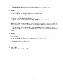
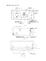
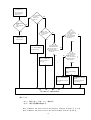
風 向 風 速 計
FV−301型
取 扱 説 明 書
INSTRUCTION
and
MAINTENANCE MANUAL
( WIND VANE & ANEMOMETER )
TYPE FV-301
WIND VANE & ANEMOMETER
はじめに
この度は、MARINE VANE をお買い求め頂きまして誠にありがとうございます。
本装置は、船舶用風向風速計で対船風向風速を測定し、そのデータをデジタル表示する装置で、その取扱方法,操
作手順,注意事項を説明しています。
ご使用になる前に必ずお読み下さい。又、大切に保管いただけます様宜しくお願い致します。
ご注意
(1)
本装置の内容は、将来予告無く変更する事があります。
(2)
本書の内容は万全を期して作成しておりますが、万一ご不審な点や誤り,記載もれ等お気付きの点がありまし
たら、ご連絡下さい。
(3)
運用した結果の影響に付いては、(2)項に関わらず責任を負いかねますのでご承知下さい。
(4)
風向風速発信器の取付は3/8インチのネジを使用し、取付台の振動等によるネジの緩みのない様しっかり締
め付けて下さい。締め付けが充分でない場合ネジが外れ、発信器が落下する事が考えられますので充分ご注意下
さい。
(5)
指示器の取付時又は前面パネルの交換時は、本指示器に供給する電源の給電を止めて下さい。又、指示器の点
検時に電源を給電したまま前面パネルを開ける時は、感電注意ステッカーの張り付けてある箇所に触れない様充
分に注意して下さい。
(6)
発信器の設置場所は通常人の手の届かない場所に設置して下さい。
プロペラ及び尾翼の回転時にプロペラ及び尾翼に触れますと大変危険です。
(7)
発信器のプロペラは絶対取り外さないで下さい。
プロペラを取り外した後取付が不完全な場合、プロペラが落下する恐れがあり大変危険です。
(8)
本装置への改造は行わないで下さい。
(9)
風向風速測定以外の目的で使用しないで下さい。
Firstly
Thank you for buying our “Marine Vane”
This instruction manual explains the handling and operating procedures and the precautions of this
device.
Please read the instructions carefully before you begin to use it. Keep this instruction manual
always available.
Precautions
(1) The contents of this device is subject to change without notice.
(2) This instruction manual is carefully prepared, however, if there is anything questionable,
wrong or missing, please notify us.
(3) Please bear in mind that we will not hold any responsibility on operational effects despite
of what is listed under paragraph (2).
(4) To install the wind direction & speed transmitter, use a 3/8 inch bolt and fasten it tight
so that the bolt will not loosen from vibration.
(5) During the installation or exchange of the front panel, turn off the power supply to the
indicator.
(6) Install the transmitter in an area where people will keep out of reach.
(7) Never remove the propeller from the transmitter. If it is removed and not correctly installed,
there is a chance that the propeller will drop which is very dangerous.
(8) Do not remodel the device.
(9) Do not use this device for other purposes besides using it as a wind direction & speed
transmitter.
1
661−036
MARINE
VANE
取扱説明書
1.概
要
本装置は、風向風速発信器により風向風速を測定しデジタル表示するもので、風速はLED7セグメ
ントにより指示すると共にバーグラフ表示をします。
又、風向は円形状にLEDが配置され、LEDの点灯により方位を表示します。
2.仕様及び定格
2.1 発 信 器
1) 型
式
プロペラ
ポリカーボネイト製
2) 起
動
風
向
2m/s以下
風
速
2m/s以下
3) 耐 風 速
最大瞬間風速
90m/s
4) 測定範囲
風
向
全方位
風
速
2∼60m/s
風
向
±5°以内
風
速
風速10m/s以下の時±0.5m/s以内
5) 精
度
10m/s以上の時±5%以内
2.2 指 示 器
1) 方
式
デジタル式
風
向
LED36ドット表示(瞬間表示)
風
速
LED31ドット表示 m/s,Kt切替
0∼60m/s
0∼60/120Kt 自動切替(×2表示)
LED7セグメント 3桁(瞬間,平均切替)
平均表示 10分間平均処理 データ更新 6秒
2) 輝度調整
可変抵抗器による(オプションによりリモコン可)
3) 出力信号
シリアルカレントループ信号(オプションによる)
4) 電
□ AC220V ±10% 50/60Hz
源
□ AC100V
±10% 50/60Hz
5) 消費電力
約20VA
6) 環境条件
使用温度範囲 −20∼40℃
使用湿度範囲 20∼80%(但し結露しないこと)
3.設
置
3.1 発信器取付
1) 発信器取付位置は出来るだけ障害物より離して自然風を測る場所を選んで下さい。発信器は軽く風
に追従する様設計製作してありますが、自身で回る力は全くありません。もしぐるぐる回る様でした
ら取付位置の不良ですから御注意願います。
2) 無線用アンテナからは出来るだけ離した弱電界の場所に設置する事をお勧め致します。
やむを得ず無線用アンテナの近くに風向風速計を取り付けた場合、無線機送信時に風向風速計が違
った値を示す事がありますが送信が終われば自動的に正常動作を行い故障ではありません。
2
3)
対震も考慮してありますが、出来るだけ震動の少ない処を選んで取り付けて下さい。
4)
取り付けの時発信器フランジにNと表示してありますので、必ず船首方向がNとなる事を確認の上ネ
ジで締め付けて下さい。位置が悪いと風向がずれて指示します。
3.2 指示器取付
1) 指示器は裏面に10φ穴2ケありますのでこの穴を利用して、ネジ又は木ネジで取り付けて下さい。
電線穴は座部と下部の二ヶ所にあります。
2) 前面パネルは、前面上部のツマミネジを2本外すと箱より内器共開く事が出来ます。前面下部の六
角穴付きボルトは外さない様注意して下さい。
3) 前面パネルの交換時、又は指示器端子の配線の為前面パネルを取り外す場合は次の手順に従って下
さい。
イ)電源スイッチをOFFにする。
ロ)コネクターCN3,CN4を外す。
ハ)図3の様にケースの端に指を掛け、親指でA方向に前面パネルを押しながら手前へ引き出すことに
より、止め金具から前面パネルを外す事が出来ます。
3.3 配
線
結線図を参考に順序に従って配線して下さい。
1) 配線方法
発信器,指示器間はMPYCS−7、電源は2芯コード、芯線断面積0.5mm2以上のものをご
使用下さい。
2) 発信器,指示器間の延長距離は、1Kmまでです。指示器のケースアースは船体アースに落として
下さい。
3) 発信器端子,指示器端子は同番号となっておりますので番号通り接続して下さい。
4) 指示器を複数接続する時は、芯線断面積0.5mm2以上の2芯シールド線を御使用下さい。
5) 配線完了後、もう一度電源⑫⑬を確認し指示器のスイッチを入れて下さい。
6) 無線機等によるノイズにより指示器が違った値を示す様な場合は、発信器グランド端子から指示器
ケースアース間に幅20mm厚さ1∼2mmの真鍮板を発信器,指示器間のケーブルに沿わせ、両機
器のグランド間を接続し、指示器側で艦船のグランドに接続する。
4.取り扱い
4.1 各スイッチの取り扱い
1) Kt,m/s切替スイッチ(S3 図1参照)
風速表示を「Kt」で行うか又は「m/s」で行うのか選択用スイッチで、スイッチが押される毎に切
替わり、「Kt」又は「m/s」表示LEDが点灯します。
2) ディマー
表示用のLEDの輝度調整ボリュームで右に回すと明るくなり、左に回すと暗くなります。
3) 瞬間,平均切替スイッチ(S2 図2参照)
スイッチS2がONの時、風速7セグメント表示が瞬間表示となりOFFの時平均表示となります。
(工場出荷時は、瞬間に設定されています。)
4) モードスイッチ(S4 図2参照)
測定モードの設定に使用し、設定の変更は電源スイッチ(S1)を一度OFFにして行って下さい。
0:測定モード
9:テストモード
注)上記以外の位置での御使用は避けて下さい。
3
4.2 風向表示
風向風速発信器の尾翼の動きに合わせて円形状に設置されたLEDが点灯します。
4.3 風速表示
風向風速発信器のプロペラの回転に合わせてLED7セグメントが0∼60.0m/s又は、0∼
120Ktを表示すると共に棒状に配置されたLEDが点灯します。
棒状LEDは全部で31個配置されています。
棒状LEDによる風速の読み取り方法は、棒状LEDで示された値の±1(×2のレンジでは±2
となります。
)の範囲に風速がある事を意味します。
(例:0∼10m/sのLEDが点灯した場合 風速値9m/s∼11m/s)
又、「Kt」のバーグラフ表示は0∼60Ktと0∼120Ktのオートレンジとなっております。
風速が60Ktを越えた時点で自動的に120Ktフルスケールに移行します。60Ktを越えると
図1に示す様に○×2「○」のLEDが点灯すると同時に棒状に配置されたLEDの点灯数はレンジ
の移行により減少します。
○×2のLEDが点灯した場合は風速バーグラフの目盛数値を2倍にして読み取って下さい。
一端60Ktを越えて120Ktレンジの状態になると、60Ktレンジに戻るまでは1時間を要
します。
5.故障点検
故障は大きくわけると次の2つにわかれますので症状によって、フローチャートの手順にそってチェ
ックを行って下さい。
尚、チェック前に各端子及びコネクターの抜けをチェックし、行って下さい。
5.1 指示器が全く点灯しない、図4による。
5.2 点灯するが動作しない、図5による。
6.予備・付属品
ミゼットヒューズ
1A
2本
4
端子カバー取付の注意
風向風速発信器のケーブルを端子に接続した後、以下の点に注意して端子カバーを取り付けて
下さい。
端子カバー取付ネジをしめる場合、図の①∼④の順番で均一に数回に分けてしめつけて下さい。
その場合、ゴム製のパッキンがめくれて、端子カバーとパッキン及び発信器の間にすき間が無
いようしめすぎに注意して下さい。すき間がありますと水が入り、発信器が破損してしまいま
す。
最後にもう一度、端子カバーが均一にしめつけられているかパッキンの広がり具合で確認して
下さい。
5
Instruction Manual for Marine Vane
1.Outline
This device measures both wind direction and wind speed with a wind direction & speed transmitter,
and digitally indicates the measured values. Wind speed is indicated not only by the 7-segment
LED but also by a bar graph. Wind direction is indicated by the lighting of circularly arranged
LEDs.
2.Specifications and Rating
2-1 Wind direction & speed transmitter
1) Type
Propeller: Made of polycarbonate
2) Start-up
Wind direction
: ≦2m/s
Wind speed
: ≦2m/s
3) Wind speed resistance : >90m/s
4) Measuring range
Wind direction
: 0mnidirectional
Wind speed
: 2∼60m/s
5) Precision
Wind direction
: ≦±5°
Wind speed
: ≦±0.5m/s (0∼10m/s)
≦±5% (10∼60m/s)
2-2 Indicator
1) Method
Digital method
Wind direction
:LED 36-dot indication (instantaneous indication)
Wind speed
:LED 31-dot indication, m/s and Kt changeover
0-60m/s
0-60/120Kt automatic change-over (×2 indication)
7-segment LED 3 digits (Instantaneous and mean change-over)
Mean method
Mean scalar
Time constant 10 minutes
2) Intensity control apparatus
Variable resistor (Option: Intensity can be controlled by remote control.)
3) Output signal
Current loop serial signal, Transmission speed: 1200 baud (Option)
4) Power supply
□ AC 220V ±10%, 50/60Hz
□ AC 100V ±10%, 50/60Hz
5) Power consumption
Approx.20VA
6) Environmental conditions
Working temperature range: 0℃-40℃
Working humidity range
: 20%-80% (Subject to non-dew condensation)
6
3.Installation
3-1 Installation of a wind direction & speed transmitter
1) In order to install a transmitter, select a position which is as far away as possible from
any obstacles so that natural draft can be measured without obstruction.
The transmitter is designed and produced so as to slightly turn in the wind. However, it can
not turn at all by itself. If the transmitter spins around, it has been installed in an inadequate
position.
2) We recommend you to install this device in a weak electric field which is away from the radio
antenna.
If this can not be avoided and the device is installed near the radio antenna, it may indicate
a digit for the automatically return to normal so do not mistaken it as breakdown.
3) Although the transmitter is designed to be vibration proof, it is advisable to install it in
a position in which there is as little vibration as possible in order to keep the transmitter
in good condition for a long time.
4) “N” is indicated on the flange of the transmitter. Therefore when installing the transmitter,
be sure to first confirm the position, then fasten the transmitter with screws. If the transmitter
is installed in an inadequate position, with direction is incorrectly indicated.
3-2 Installation of indicator
1) There are two holes 10Φ in diameter on the reverse side of the indicator. Therefore install
the indicator by putting screws or wood screws in the holes. The indicator is also provided
with a separate hole for an electric wire.
2) In order to open the inside of the indicator, remove the tow thumb screws on the upper part
of the front. However, take care not to remove any of the bolts of the hexagon socket head on
the lower part of the front.
3) When exchanging or removing the front panel to do the wiring of the indicator terminal, do
it in the following procedures:
(1) Turn the switch off.
(2) Remove connectors CN-3 and CN-4.
(3) Put your finger on the edge of the case as in Diagram 3 and while the thumb is pressing
the front panel in direction “A” pull the case and the front panel can be easily separated
from latch.
3-3 Wiring
As for wiring, refer to the attached connection diagram, and wire in the order indicated.
1) How to wire
In order to connect the transmitter and the indicator, use a MPYCS-7. For power supply, use
a 2-core cord 0.5mm2 or more in the sectional area.
2) The wiring distance between the transmitter and the indicator is limited to 1km or less.
3) The terminal number of the transmitter is the same as that of the indicator.
Therefore connect the same terminal numbers, connect the case earth to the frame ground.
4) In order to connect the indicator with plural apparatus, use 2-core shielded wires 0.5mm2 or
more in the sectional area.
7
□AC100V±10%
5) As for power supply, use it within the range of □AC220V±10% and at a frequency of 50 or 60Hz.
When wiring work has been completed, once more verify that power supplies ⑫ and ⑬ are connected.
Then turn on the indicator switch so that the indicator can operate.
6) When the indicator does not work in the correct way because of the noise generated from the
radio, please take measures as follows.
Connect the transmitter’s ground terminal to the indicator’s case earth by a brass sheet,
one or tow millimeters thick and twenty millimeters wide.
Connect the indicator’s case earth to the frame’s ground by a brass sheet, one or tow
millimeters thick and twenty millimeters wide.
4. Handling
4-1 Handling of each switch
1) Kt and m/s change-over switch (Refer to Fig.1 of S3.)
This is a switch for selecting whether the wind speed indication is given by “Kt” or by “m/s”.
Every time the switch is pressed, the indication is switched over from one unit to another,
and then the “Kt” indication LED or the “m/s” indication LED is lit.
2) Dimmer
In order to make the indication LED bright, turn the brightness control volume for the LED
to the right.
In order to make it dark, turn it to the left.
3) Instantaneous mean change-over switch (Refer to Fig.2 of S2.)
When the switch S2 is turned on, the 7-segment indication of wind speed is switched over to
the instantaneous indication; when it is turned off, it is switched over to the mean indication.
4) Mode switch (Refer to Fig.2 of S4.)
Use it for a setup of measuring mode. In order to change a setup, first turn off the power
supply switch S1, then change a setup.
0:Measuring mode
(When you receive the signal from a transmitter, please set a mode switch S4 as
"0".)
7:Indicator Increase Mode (When you receive the signal from an indicator, please set a
mode switch S4 as "7".)
Note) Take care not to use the indicator at positions other than those mentioned above.
4-2 Indication of wind direction
Circularly arranged LEDs are lit according to the movement of the tail of a wind direction
& speed transmitter.
4-3 Indication of wind speed
The 7-segment LED indicates, as shown in Fig.1 value within the range of 0-60. 0m/s or within
the range of 0-120Kt according to the rotation of a wind direction & speed transmitter
propeller.
Simultaneously, cylindrically arranged LEDs are lit. The total number of cylindrically
arranged LEDs is 31.
How to read wind speed indicated by cylindrically arranged LEDs: Value indicated by the
cylindrically arranged LEDs shows that wind speed is within the range of ±1 of the value
(within the range of ±2 in the case of the × 2 range).
For example, if LEDs for 0-10m/s are lit, wind speed is 9m/s-11m/s.
8
The bar graph indication of “Kt” is given either by the “0-60Kt” range or by the automatic
“0-120Kt” range.
When wind speed exceeds 60Kt, the range “0-60Kt” is automatically shifted to the full-scale
range “0-120Kt”.
Namely, when wind speed exceeds 60Kt, the LED “0” of ○×2 is lit as shown in Fig.1 and
simultaneously, the number of cylindrically arranged LEDs to be lit decreases with the
shifting of the range.
When the LED○ of ○×2 is lighting, read the value of Kt by doubling each numerical gradation
for wind speed.
Once wind speed has exceeded 60Kt, it takes an hour before the 0-120Kt range changes back
into the 0-60Kt range.
5. Troubleshooting
There can be two causes in case you have problems with the device. Fellow the flowchart and
check whether it pertains to your problem. Also, before you do this, check each terminal and
connector so that it is not disconnected.
5-1 The indicator does not blink. Figure 4 is the reason.
5-2 The indicator blinks but will not operate. Figure 5 is the reason.
6. Spare parts and accessories
Midget fuse 1A 2pcs.
9
Cautions of terminal cover attachment
Please attach a cautions terminal cover in the following points after connecting the cable
of wind direction & speed transmitter to a terminal.
When a terminal cover attachment screw is screwed up, please close in several steps in
order of ① to ④ uniformly.
In this case, be careful there you be no crevice.
Finally, once again, the terminal cover is bound tight uniformly or please check in the spread condition
packing.
10
11
スイッチを入れても
LEDが点灯しない。
The LED does not
blink although the
switch is on.
ヒューズが切れ ているか?
Did the fuse
blow out?
AC電源が来てな
いか?
Is the voltage AC
Power?
NO
NO
YES
ボリュームが
絞られているか?
Is the volume olled?
YES
NO
スイッチングレギレー
ターの5Vが出ていな
いか?(注1)
Does the switching
regulator indicate
5V?<Note1>
AC電源を入れる。
NO
YES
Send AC Power.
YES
スイッチを入れ直し
正常に動作するか?
Turn the switch on
again and check
whether it went back
to normal?
ヒューズを入れ換える。
Change the fuse.
YES
NO
NO
ボリュームを右に回す。
スイッチングレギレ
ーターに100V IN
が有るか?(注2)
Does the switching
regulator indicate
100V?<Note2>
Turn the volume to
the right.
YES
スイッチングレギレーター
を交換する。
Exchange the switching
regulator.
ACラインの端子等を調べ
る。
指示器基板(03-947)を交
換する。
Check the terminal of the
AC Line.
Exchange the indicator
bound (03-947)
正 常 動 作
Normal operation
図 4・4.Fig
(注1):端子①を+、②を−にし、測定する。
(注2)
:端子④⑤番間で測定する。
Note 1:Measure the wind direction and speed by changing Terminal ① to +②
Note 2:Measure the wind direction and speed between Terminal ④ and ⑤
12
前 面 LEDは 、点 灯 す る が 動
作 しな い 。
The front panel LED lights
up but does not operate.
テ ス トモ ー ド が 動
作 しな い ? (注 1)
Does the test
m ode operate?
YES
風 速 が 動 作 しな い 。
W ind direction m easuring
device does not generate.
W ind speed m easuring devices does not operate.
NO
風向風速共に動作し
ない?
Both wind direction
and speed m easuring
divice does not
generate?
指示器基板裏面の
LED⑩ が 点 滅 し て い
るか?
LED⑩ on the back
panel of indicat or
board lights up
blinks?
NO
NO
YES
NO
風 向 が 動 作 しな い 。
LED⑪ が 点 滅 し て
い る か ?
LED⑪ light up blinks?
発 信 器 へ の 3番 端 子 を
外 し− ②番 +③ 番間
が 12Vか ?
Disconnect ternim al 3
from the transm itter
and it indicator 12V
between− ② and +③ ?
YES
YES
発 信 器 、指 示 器 間 の
断 線 ① 又 は 、そ の 端 子
の接続不良か?
W ire ① between the
transm itter and
indicator is cut off or
contact failure with
the ternim al?
YES
発 信 器 へ の 3番 端 子 を つ な
ぐ。
Connect ternim al 3 to the
transm itter.
発 信 器 、指 示 器 間 の
断 線② ③又 は、その 端
子の接続不良か?
W ires ② ③ between
transm itter and
indicator is cut off or
contact failure with
the ternim al?
NO
LED⑦ ⑧ が 点 滅
してい るか ?
LED⑦ and ⑧
lights up blinks?
YES
NO
YES
NO
YES
NO
発 信 器 、指 示 器 間 の
断 線 ⑥⑤ ④又 は、その
端子の接続不良か?
W ires ⑥ ⑤ ④ between
the transm itter and
indicator one cut off
or contact failure with
the ternim al?
NO
YES
断 線 又 は 、接 続 不 良 を 直
す。
Either wire is cut off or
contact failure.
指 示 器 基 板 (03-947)を 交
換する。
発 信 器 を 交 換 す る 。
Exchange the transm itter.
Exchange indicator board
to (03-947)
正 常 動 作
N orm al operation
図 5・5.Fig
(注1)
:電源スイッチを OFF にし、モードスイッチ(S4)を 9 に合わせて再度電源スイッチを ON にして下
さい。モードスイッチを 9 に合わせると、テストモードとなり 1 秒間に風向が、36.9.18.27 方位
と変化し、風速は 0.15.30.60m/s と変化します。
Note 1:Turn switch off adjust mode switch (S4)to 9 and turn switch on again. When mode switch
is adjusted to 9. It will switch over to the test mode and the wind direct will change to
36.9.18.27per second and wind speed will change to 0.15.30.60m/s.
13
14
15


![TC-L10表 [更新済み]](http://vs1.manualzilla.com/store/data/006535690_2-3745340c10e55cb036af6a2ee28aeab8-150x150.png)