1
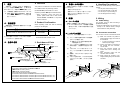
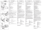
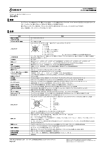
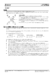
【配線図】[WIRING DIAGRAM]
(AJ65BT-D75P2-S3 側) (AJ65BT-D75P2-S3 side)
(MR-J2A 側) (MR-J2A side)
AX□
CN1A
19 RD
9 COM
READY
7
COM
26
INPS
8
PGO
24
18 INP
5 LZ
PGO COM
25
15 LZR
CLEAR
5
8
CLEAR COM
23
PULSE F+
3
CR
10 SG
3 PP
PULSE F-
21
13 PG
PULSE R+
4
PULSE R-
22
36 NP
3 NG
プレート
SD (Plate)
CN1B
SON
29
5
SON
ABSM
30
8
PC
ABSR
31
9
TL
D01
17
4
ZSP
18
TLC
34
D01
19 ZSP
6 TLC
中継端子台
Relay terminal block
PULSE A+
9
PULSE A+
PULSE A-
27
PULSE A-
PULSE B+
10
PULSE B+
PULSE BDOG
28
PULSE B-
11
DOG
FLS
12
FLS
RLS
13
RLS
STOP
14
STOP
CHG
15
CHG
STRT
16
STRT
COM
35
COM
COM
36
COM 33
33
COM 33
32
COM 32
COM 32
プレート
(Plate)
手動パルサ Manual pulser
(MR-HDP01)
5V
A
中継端子台
Relay terminal block
DC24V
PC
TL
RA2
ZSP
RA3
TLC
RA1
ALM
18 ALM
EMG
VDD
15 EMG
3 VDD
COM
13 COM
RES
14 RES
16 LSP
LSP
LSN
SG
SG
SD
P15R
TLA
LG
17 LSN
10 SG
20 SG
11 P15R
12 TLA
1 LG
※下記信号線は機器構成に関わらず,必ず配線してください。配線を行わない
場合,位置決め制御を行うことができません。
D75P2 側
・FLS(上限リミット)
・RLS(下限リミット)
MR-J2□A 側
・LSP(正転ストロークエンド)
・LSN(逆転ストロークエンド)
・EMG(非常停止)
∗ Make sure to conduct wiring of the follwing signal wire regardless of the machnine
configuration. If wiring is not conducted then positionig control cannot be conducted.
D75P2 side
・FLS (upper limit)
・RLS (lower limit)
MR-J2 A side
・LSP (forward stroke end)
・LSN (reverse stroke end)
・EMG (emergency stop)
※外部機器接続ケーブルの信号名称および用途,配線については,「三菱汎用
AC サーボ MELSERVO-J2-A 仕様取扱説明書」「AJ65BT-D75P2-S3 形位置決めユ
ニットユーザーズマニュアル」を参照してください。
∗ About the signal mame, application and wiring of the external device
connection cable, please refer to "MITSUBISHI AC Servo MELSERVO-J2-A
Specification Handling Manual" and "AJ65BT-D75P2-S3 Positioning Module
User's Manual".
Warranty
・Mitsubishi will not be held liable for damage caused by factors found not to be
the cause of Mitsubishi; machine damage or lost profits caused by faults in the
Mitsubishi products; damage, secondary damage, accident compensation
caused by special factors unpredictable by Mitsubishi; damages to products
other than Mitsubishi products; and to other duties.
保証について
当社の責に帰すことができない事由から生じた損害,当社製品の故障に起因す
るお客様での機会損失,逸失利益,当社の予見の有無を問わず特別の事情から生
じた損害,二次災害,事故補償,当社製品以外への損傷およびその他の業務に対
する保証については,当社は責任を負いかねます。
安全にお使いいただくために
・この製品は一般工業を対象とした汎用品として製作されたもので,人命にかか
わるような状況下で使用される機器あるいはシステムに用いられることを目
的として設計,製造されたものではありません。
・この製品を原子力用,電力用,航空宇宙用,医療用,乗用移動体用の機器あるい
はシステムなどの特殊用途への適用をご検討の際には,当社の営業担当窓口ま
でご照会ください。
・この製品は厳重な品質管理体制の下に製造しておりますが,この製品の故障に
より重大な事故または損失の発生が予測される設備への適用に際しては,バッ
クアップやフェールセーフ機能をシステム的に設置してください。
For safe use
・This product has been manufactured as a general-purpose part for general
industries, and has not been designed or manufactured to be incorporated in a
device or system used in purposes related to human life.
・Before using the product for special purposes such as nuclear power, electric
power, aerospace, medicine or passenger movement vehicles, consult with
Mitsubishi.
・This product has been manufactured under strict quality control. However,
when installing the product where major accidents or losses could occur if the
product fails, install appropriate backup or failsafe functions in the system.
C 1998 MITSUBISHI ELECTRIC CORPORATION
本マニュアルは,輸出する場合,経済産業省への役務取引許可申請は不要です。
三菱電機株式会社 〒100 東京都千代田区丸ノ内2-2-3(三菱電機ビル)
of Economy, Trade and Industry for service transaction permission.
When exported from Japan, this manual does not require application to the Ministry
MODEL
形名
コード
MODEL
CODE
AD75P-MR-J2A-U
13JM62
AD75C20SNJ2 形 AJ65BT-D75P2-S3-MR-J2□
AJ65BT-D75P2-S3-MR-J2□A 接続ケーブルユーザーズマニュアル
AD75C20SNJ2 AJ65BT-D75P2-S3-MR-J2 A Connection Cable User's Manual
IB(
IB(名
IB(名)-68926-B(0410)MEE
●安全上のご注意●
(ご使用前に必ずお読みください)
本製品のご使用に際しては,本マニュアルをよくお読みいただくと共
に,安全に対して充分に注意を払って,正しく取扱いをしていただくよ
うお願いいたします。
本マニュアルで示す注意事項は,本製品に関するものについて記載し
たものです。シーケンサシステムとしての安全上のご注意に関しては,
CPUユニットのユーザーズマニュアルをお読み下さい。
このマニュアルでは,安全注意事項のランクを「危険」,「注意」とし
て区分してあります。
●SAFETY PRECAUTIONS●
(Read these precautions before using.)
When using Mitsubishi equipment, thoroughly read this manual and the associated
manuals introduced in the manual. Also pay careful attention to safety and handle
the module properly.
These precautions apply only to Mitsubishi equipment. Refer to the CPU module
user’s manual for a description of the PC system safety precautions.
These ●SAFETY PRECAUTIONS● classify the safety precautions into two
categories: “DANGER” and “CAUTION”.
危険
取扱いを誤った場合に,危険な状況が起こりえて,
死亡または重傷を受ける可能性が想定される場合。
DANGER
Procedures which may lead to a dangerous condition
and cause death or serious injury if not carried out
properly.
注意
取扱いを誤った場合に,危険な状況が起こりえて,
中程度の傷害や軽傷を受ける可能性が想定される場
合および物的損害だけの発生が想定される場合。
CAUTION
Procedures which may lead to a dangerous condition
and cause superficial to medium injury, or physical
damage only, if not carried out properly.
注意に記載した事項でも,状況によっては重大な結果に結びつく
なお,
可能性があります。
いずれも重要な内容を記載していますので必ず守ってください。
本マニュアルは必要なときに読めるよう大切に保管すると共に,必ず最終需
要家までお届けいただくようお願いいたします。
SON
B
形名
【取付け上の注意事項】
注意
● D75P2およびMR-J2□Aとの接続は,D75P2およびMR-J2□A
のコネクタに確実に装着し,カチッという音がすること
を確認してください。正しく装着されていないと接続不
良となり,誤入力,誤出力の原因になります。
● 取付け,配線作業などは,必ず電源を外部にて全相遮断
してから行ってください。全相遮断しないと,感電ある
いは製品の損傷の恐れがあります。
【配線上の注意事項】
注意
● D75P2と外部機器,およびMR-J2□Aと外部機器の配線は
接続する外部機器の定格電圧およびケーブルのリングマ
ークに記載の端子名を確認した上で正しく行ってくださ
い。定格と異なった電源を接続したり,誤配線をすると,
火災,故障の原因になります。
● D75P2側コネクタにコネクタカバーを装着する場合は,
切粉や配線クズなどの異物が入らないように注意してく
ださい。火災,故障,誤動作の原因になります。
● 出力用電源端子で使用しない端子は,絶縁してください。
火災,故障,誤動作の原因になります。
【保守・廃棄上の注意事項】
保守 ・廃棄上の注意事項】
注意
● 製品は,分解・改造をしないでください。故障,誤動作,
ケガ,火災の原因になります。
● 製品を廃棄するときは産業廃棄物として扱ってくださ
い。
Depending on circumstances, procedures indicated by
CAUTION may also be
linked to serious results.
In any case, it is important to follow the directions for usage.
Store this manual in a safe place so that you can take it out and read it whenever
necessary. Always forward it to the end user.
[INSTALLATION PRECAUTIONS]
CAUTION
● For the connection between D75P2 and MR-J2 A, be sure the
D75P2 and MR-J2 A connectors are securely connected until a
clicking sound is heard. If not correctly connected the connection
will be bad and will cause erroneous input and output.
● Make sure to switch all phases of the external power supply off
when installing or placing wiring. If do not switch off the external
power supply, it will cause electrick shock or damage to the
product.
[WIRING PRECAUTONS]
CAUTION
● When wiring the D75P2 to external divice or the MR-J2 A to
external device, make sure to conduct the wiring correctly while
checking the rated voltage and terminal name written on the cable
ring mark. Connecting a power supply different from the rated
voltage or making an incorrect wiring would cause fire and
breakdowns.
● When installing the connector cover to the D75P2 connector,
make sure that no foreign objects , such as filings or wire chips,
get inside the connector. Not doing so could cause fire,
breakdowns, and malfunction.
● Insulate terminals not used as output power supply terminals. Not
doing so could cause fire, breakdowns, and malfunction.
[MAINTENANCE AND DISPOSAL RECAUTIONS]
CAUTION
● Do not disassemble or renovate the product. Doing so could
cause trouble, malfunction, injury to fire.
● When disposing of this product, treat it an industrial waste.
Overview
1. 概要
1.
本製品は,「AJ65BT-D75P2-S3 形位置決めユ
ニット」(本書では D75P2 と略す)と「MR-J2□A
形サーボアンプ」(本書では MR-J2 と略す)およ
び,「外部機器」を接続するためのケーブルです。
※ 接続/配線/製品の使用の際は,本書と併
せて,D75P2
D75P2,MR-J2
D75P2
MR-J2 のマニュアルを必ず参
照してください。
This product is a cable that is connected between
the AJ65BT-D75P2-S3 positioning module
(hereafter D75P2) and the MR-J2 A servo
ampifier's (hereafter MR-J2) and external device.
∗ When connecting, wiring and using this
product, please make sure to refer to both
manuals D75P2 and MR-J2 in conjunction
with this muanual.
2.製品確認
2. Product Confirmation
開梱の際は,下記の製品に損傷がないことを確
認してください。
When unpacking, make sure that the following
product is not damaged.
品名(
)
品名 ( Model)
形名(
)
形名 ( Type)
個数(
個数(Quantity)
Quantity)
AJ65BT-D75P2-S3-MR-J2A 接続ケーブル
(AJ65BT-D75P2-S3-MR-J2A Connection Cable )
AD75C20SNJ2
1
※ D75P2 側のコネクタカバーは,D75P2 に付属の
コネクタカバーを使用します。
3.各部の名称
∗ A connector cover attached to D75P2 is used
as the D75P2 side connector cover.
3. Each Name of Parts
D75P2-MR
D75P2 MR-J2
MR J2 間接続ケーブル
L=2000mm (78.74 inch)
D75P2 側コネクタ
(AX□)
L=2000mm
(78.74 inch)
リングマーク
(端子名を記載)
D75P2-外部機器間接続ケーブル
D75P2
外部機器接続用端子
(M3.5ネジ用圧着端子×13本)
MR-J2
MR J2 側コネクタ
(CN1A)
MR-J2
MR J2 側コネクタ
(CN1B)
L=2000mm (78.74 inch)
MR-J2MR J2-外部機器間接続ケーブル
J2外部機器接続用端子
(M3.5ネジ用圧着端子×17本)
① D75P2 side connector (AX )
② Connection cable between the D75P2 and MR-J2
③ MR-J2 side connector (CN1A)
④ MR-J2 side connector (CN1B)
⑤ Ring mark (where terminal name is written)
⑥ Connection cable between the D75P2 and external device
⑦ Terminal for external device connention (M3.5 screw soderless terminal × 13)
⑧ Terminal for external device connention (M3.5 screw soderless terminal × 17)
⑨ Connection cable between the MR-J2 and external device
4. 取扱い上のお願い
4. Handling Precautions
本製品は下記の点にご注意いただけますようお願
いいたします。
・鋭利なもので圧迫しない
・極端にねじったり強く引っ張ったりしない
・踏みつけたり上に物を置いたりしない
・被膜を傷つけない
Take notice of the following points regarding this
product.
・Do not press with somethig sharp
・Do not twist extremely or pull hard
・Do not step on or put somthing on
・Do not damage the thin coating
5. 配線
5. Wiring
5.1 ケーブル配線
5.1 Cable wiring
本製品は【配線図】に従って配線してください。
※ ケーブルの長さが足りず,外部機器に直接接
続できない時は,外部に中継用の端子台を設
けてください。
5.2 コネクタの接続
コネクタは,下記の要領で接続してください。
(1) ユニット本体の電源が外部にて全相遮断
されているか確認します。
※ 遮断されていない場合は電源を外部に
て全相遮断します。
(2) ユニットのコネクタ接続部とコネクタの
形状を確認し,接合部の向きを合わせま
す。
(3) コネクタは,ユニット側にまっすぐ「カ
チッ」という音が聞こえるまで押し込み
ます。
(4) 接続後,コネクタにガタつきがないかを
確認します。
(5) コネクタを外す時は,コネクタの左右の
ツマミをしっかり押え,まっすぐ引き抜
きます。
This product must be wired according to the
[WIRING DIAGRAM].
∗ When the cable length is not enough to connect
directly to the external device, configure the
terminal block for relay externally.
5.2 Connector connection
The connector must be connected as following :
(1) Make sure whether all phases of the
external power supply of the main module
is switched off.
∗ In case of not doing so, switch off the
external power supply.
(2) Confirm the shape of connecting part of
the module and the connector, then
connect them.
(3) Push the connector straight into the
module side until a clicking sound is
heard.
(4) After connected, make sure that the
connector does not rattle.
(5) When unplug the connector, pull it out
straight holding firmly the both side of the
connector.