Transcript
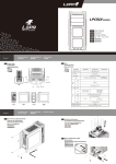
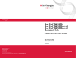
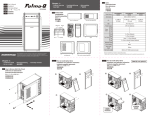
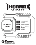
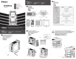
Chapter 1 :
1.2 Accessories
Zubehör
Wyposażenie
•Product Overview•Produkteinführung
•Opis produktu•製品の説明•產品槪觀 Figure
Purpose
7
PSU/Add-on card installation
Motherboard screw
9
Motherboard installation
製品ビュー
Fan screw
4
Front fan installation
両サイドパネルの取り外し
產品外觀
Stand-off
9
Motherboard installation
兩側側板拆卸
Meshed slot cover
1
Slot cover
HDD rail
6
HDD installation (upper cage)
Speaker
1
Speaker installation
Cable tie
9
Cable management
c. Right Side
b. Left Side
(optional)
ECA3250 Series
User’s Manual
Handbuch
Instrukcja obsługi
ユーザ マニュアル
e. Top
使用手冊
d. Rear
ECA3250 Series
(D) 480 x (W) 200 x (H) 460
Material
SGCC
3.5”硬碟安裝
a.
1 (exposed) +5 (hidden)
M/B
ATX, Micro ATX
ATX 12V (Optional)
I/O
USB 3.0 x 1, USB 2.0 x 3, HD/AC97’ Audio
Side
HDD LED
2.4 How to Remove the Upper HDD cage
Entfernen des oberen Festplattenkäfigs
Demontaż górnej klatki HDD
上部ハードディスク用ブラケットの外し方
a.
4
3.5 ”
Front
Power LED
5.25 ”
Power Supply
Fan Slots
Power
移除上層硬碟磁架
b.
ODD
1
c.
2.2 How to Install the External 5.25” and 3.5” Devices
Installation externer 5,25”- und 3,5”-Laufwerke
Instalacja napędów 5,25” i 3,5”
5インチと3.5インチ外付けデバイスの取り付け方法
光碟機 、軟碟機安裝
FDD
a.
2 x 14/12cm (Optional)
1 x 12cm
Top
2 x 14/12cm
Bottom
1 x 12cm
Expansion Slots
7
Liquid Cooling Holes
2
2
*Product specifications are subject to change without notice.
*Options vary by countries or regions.
For detailed information please visit our website at www.enermax.com
2.6 How to Install System Fans
Installation der Systemlüfer
Instalacja wentylatorów systemu
機箱風扇安裝
3
1 x 12cm
Rear
ケースファンの取り付け
UNLOCK
2
產品規格
Dimensions (mm)
USB Ports
Reset
2.1 How to Remove Both Side Panels
Entfernen der Seitenwände
Demontaż panelów bocznych
スペック
Model Number
Headset Mic
©2012 ENERMAX Technology Corporation. All rights reserved. Specifications are subject to change without
prior notice. Actual product and accessories may differ from illustrations. Omissions and printing errors
excepted. Content of delivery might differ in different countries or areas. Some trademarks may beclaimed as
the property of others. Reproduction in any manner without the written permission of ENERMAX is strictly
forbidden
b.
LOCK
1.3 Specs
Technische Daten
Dane techniczne
Drive Bays
f. I/O Close-up
内部3.5インチデバイスの取り付け
•Installation Guide•Montageanleitung•Instrukcja montażu
•取り付けの説明•組裝說明
Q’ty
a. Front
2.3 How to Install Internal 3.5“ Device
Installation von internen 3,5“-Laufwerken
Instalacja wewnętrznych napędów 3,5“
Chapter 2 :
零件盒
PSU/PCI slot screw
1.1 Product View
Produktskizze
Opis produktu
Parts Name
アクセサリ
LOCK
1
UNLOCK
Chapter 3 :
Chapter 4 :
•Cable Connection Description•Anschlussübersichtg
•Instrukcja montażu •ケーブル接続の説明
•線材安裝說明
•Suggested Height of CPU Cooler and Length of VGA card
•Empfohlene Höhe des CPU-Kühlers und Länge der
Grafikkarte
•CPUクーラーの高さとVGAカードの長さについて
Motherboard
Panel Connector
Cable
Panel Connector
High Definition Audio (Azalia)
HD Audio Connector
AC’97
AC’97 Connector
Top Panel USB 2.0 Connector
USB 2.0 Connector
•CPU cooler高度及顯示卡長度建議
D
HD
DD
H
2.5 How to Install Add-on Cards
Installation von Erweiterungskarten
Instalacja kart rozszerzenia
286.3 mm
413.8 mm
アドオンカードの取り付け
安裝擴充卡
b.
a.
b.
Top Panel USB 3.0 Connector
USB 3.0 Connector
D
HD
149.8 mm
174.8 mm
Notice:
On some motherboards, the connectors might not be exactly the same as the drawings above, please
check with your motherboard manual before installing.
Bei einigen Mainboards ist der Stecker unter Umständen nicht identisch mit dem auf der Zeichnung
oben.
Wtyczki niektórych płyt głównych mogą odróżniać się od tych na rysunku powyżej. Proszę również
przeczytać instrukcję obsługi płyty głównej przed instalacją.
LOCK
UNLOCK
マザーボードによってはコネクタ類の形状が上の図面と異なる場合がございます。詳しくはマザーボードの取扱説明書をご参
照ください。
圖面所示之線材可能與使用之主機板不儘相同, 安裝前請參考主機板廠所提供之說明書。
w/ fan
w/o fan