Transcript
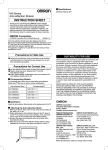
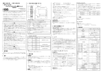
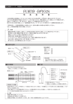
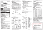
2 外形寸法
1 各部の名称
形 G9SA-EX301 形 G9SA-EX031-T□
33 41
13 23
セーフティリレーユニット
(増設ユニット)
出力端子
はじめに
14 24
このたびは、形G9SAセーフティリレーユニットをお買い上げいただきまして、
まことにありがとうございま
す。
この取扱説明書では、形G9SAを使用する上で、必要な機能、性能、使用方法などの情報を記載し
ています。形G9SAをご使用に際して下記のことを守ってください。
・形G9SAは電気の知識を有する専門家が扱ってください。
・この取扱説明書をよくお読みになり、
十分にご理解のうえ、
正しくご使用ください。
・この取扱説明書はいつでも参照できるよう大切に保管ください。
Two, 4.2 dia. or M4
33 41
電源表示
Type G9SA-EX301 Type G9SA-EX031-T□
91
動作表示
Japanese
87±0.3
オフディレ−時間設定スイッチ
(G9SA-EX031-T□)
出力端子
English
10.5
8-M3
5.9
取付穴加工寸法
φ4.6
7
9
規格
形G9SAシリーズは以下の規格に従い、
設計/製造されています。
- EN ISO13849-1: 2008 PL e Category 4
- EN 60947-5-1: 2004
- UL508, CAN/CSA C22.2 No.14
5.6
安全上のご注意
4 定格・性能
2VA以下/2W以下
3 N.O.
13/14,23/24,33/34
a 接点 *1)
オフディレー接点 *1)*3)
出力
b 接点 補助接点 *2)
●禁止図記号の一般
特定しない一般的な禁止の通告。
定格負荷
IEC60947-5-1
Table 4
●強制図記号の一般
特定しない一般的な使用者の行為を指示する図記号。
定格通電電流
接点電圧の最大値
●警告表示
警 告
出力が故障し、
重度の人身傷害が万一の場合起こる恐れがあります。
安全出力の定格値を超える負荷に対しては、
絶対に使用しないでください。
安全機能が損なわれ、
重度の人身傷害が万一の場合起こる恐れがあります。
安全出力が供給電源および負荷電源に短絡しないように、
適切に配線してください。
安全上の要点
(1)配線をおこなう場合には必ず電源を切った状態でおこなってください。
また通電中はカバーを取り付
けた状態とし、端子部には触れないで下さい。感電の恐れがあります。
(2)落雷の恐れがある場合には配線作業を行わないでください。感電の恐れがあります。
(3)入力端子には規定の電圧を正しく印加してください。誤った電圧を印加されますと規定の機能が発
揮されず、製品自体の破損・焼損の原因になります。
(4)開閉容量
(接点電圧、接点電流)
などの接点定格値を越える負荷に対しては、絶対に使用しないで
ください。絶縁不良、接点溶着、接触不良など、規定の性能を損なうばかりでなく、破損、焼損の原因
となります。
(5)耐久性は開閉条件により大きく異なります。使用にあたっては必ず実使用条件にて実機確認をおこ
ない、性能上問題のない開閉回数内にてご使用ください。
また、性能が劣化した状態で引き続きご
使用されますと、最終的には回路間の絶縁破壊や、製品自体の焼損などの原因となります。
(6)引火性ガス・爆発ガスなどの雰囲気では使用しないでください。開閉にともなうアークやリレーの発熱
などにより、発火または爆発を引き起こす原因となります。
(7)落下させたり内部を分解した製品は、使用しないでください。特性を満足できないばかりでなく、破損、
焼損の原因となります。
(8)負荷の短絡、地絡防護のため、必要に応じ適切な保護素子
(公称電流5A以下のヒューズなど)
を
接続ください。保護できない場合には、破損または焼損の可能性があります。
使用上の注意
(1)取り扱いについて
1.製品を落下させたり、異常な振動衝撃を加えないでください。故障や誤動作の原因となります。
2.G9SA-EX031-T□において、
オフディレー時間を設定するボリュームスイッチは、MIN値および
MAX値の目盛り以上は回転させないで下さい。目盛り以上に回転させますと、製品が破損する恐れ
があります。
(2)溶剤の付着について
製品にアルコール、
シンナー、
トリクロロエタン、
ガソリンなどの溶剤が付着しないようにしてください。
溶剤により、
マーキングの消えや、部品の劣化を引き起こす原因となります。
(3)保管・設置場所について
下記の場所には故障や誤動作の原因となりますので設置をしないでください。
1.直接日光が当たる場所。
2.周囲温度が-25∼55℃の範囲を越える場所。
3.相対湿度が35∼85%RHの範囲を越える場所、温度変化が急激で結露するような場所。 4.周囲気圧が86∼106kPaの範囲を越える場所。
5.腐食性ガスや可燃性ガスのある場所。
6.本体に定格値以上の振動や衝撃が伝わる場所。
7.水、油、薬品などの飛沫がある場所。
8.塵埃、塩分、鉄粉の多い場所。
(4)多数個取付けについて
密着取付する場合は、定格通電電流は、
3Aとなります。
3A以下でご使用ください。
(5)配線について
1.配線用電線サイズは下記のものをご使用ください。
・ヨリ線
(flexible wire)
:0.75∼1.5mm2
・単線
(steel wire)
:1.0∼1.5mm2
2.端子ネジは誤動作、発熱などの原因にならないように、規定のトルクで締め付けてください。
・端子ネジ締め付けトルク:0.78∼1.18N・m
(6)この商品は
「c
l
assA」(工業環境商品)
です。住宅環境でご利用されると、電波妨害の原因となる可
能性があります。
その場合には電波妨害に対する適切な対策が必要となります。
(7)本体ユニットへの接続について
本体ユニットのコネクタカバーをはずし、増設ユニットの接続ケーブルのコネクタを差し込み接続して
ください。
(通電前にコネクタ部のロックがされていることを確認してください。)
--3 N.O.
13/14,23/24,33/34
1 N.C. 41/42
---
1 N.C. 41/42
AC250V 5A cosφ=1 DC30V 5A L/R=0ms
AC240V 2A cosφ=0.3
AC15
DC13
DC24V 1A L/R=48ms
5A
AC250V DC125V
定格短絡電流
1,000A
*1)安全出力 *2)非安全出力
*3)G9SA-EX031-T□がオフディレー時間中に安全入力が再投入された場合には、
リセットモードに応じて次のように
動作します。
・オートリセットモード:オフディレー時間が終了して一度出力がOFFしてから、
出力がONになります。
・マニュアルリセットモード:オフディレー時間が終了して一度出力がOFFしてから、
リセット入力が入った時点で
出力がONになります。
●オフディレー時間
形G9SA-EX031-T□
最大オフディレー設定時間/15 段階
-T015
1.5秒
-T075
7.5秒
-T15
15秒
10.5
Output terminals
Eight,M3
5.9
Mounting holes
4.6 dia.
-T30
30秒
●性能/絶縁性能/耐久性/保護構造/汚染度
本体ユニットと同じ仕様
5 性能レベルおよび安全カテゴリについて(EN ISO13849-1)
形G9SAは、欧州規格EN ISO13849-1より要求される性能レベルでPL=eおよび安全カテゴリ4の環
境に適用することができます(G9SA-EX031-T□は、性能レベルPL=dおよび安全カテゴリ3の環境に
適用することができます。)
。ただし、
この設定は当社が提示しています回路例および使用条件をもとに判
定されたものであり、
ご使用状況によっては当てはまらない場合があります。
安全カテゴリは安全制御システム全体で判定されますので、
ご使用の際には十分ご確認いただきますよ
うお願いします。
・パフォーマンスレベル算出の使用条件(EN ISO13849-1)
- Category 4 (G9SA-EX031-T□:Category 3)
- DCavg:High (G9SA-EX031-T□:Low)
- CCF:65点以上
- MTTFd:G9SA-EX301:100年、G9SA-EX031-T□:65年
* MTTFd は下記の稼働条件を基に算出したものです。
- Nop=31,680回/年(dop=220日/年、hop=12時間/日、t cycle=300秒/回)
ご使用に際してのご承諾事項
本製品は機械安全用途に使用されるコンポーネント商品ですが、使い方によっては要求される安全性が
確保できない場合があります。セーフティコンポーネント総合カタログ巻頭の「警告」
に記載されている
「①リスクアセスメントの実施②安全方策③安全機器の役割④安全機器の設置⑤法令の遵守⑥使用
上の注意事項⑦装置・設備移転・譲渡」
を遵守の上ご使用ください。
a) 屋外の用途、潜在的な化学的汚染あるいは電気的妨害を被る用途またはカタログ、
取扱説明書等に
記載のない条件や環境での使用
b) 原子力制御設備、焼却設備、鉄道・航空・車両設備、医用機械、娯楽機械、
および行政機関や個別
業界の規制に従う設備
c) 人名や財産に危害が及びうるシステム・機械・装置
d) ガス、水道、電気の供給システムや24時間連続運転システムなど高い信頼性が必要な設備
e) その他、上記a)
∼d)
に準ずる、高度な信頼性が必要とされる用途
* 上記は適合用途の条件の一部です。当社のベスト、総合カタログ、データシート等最新版のカタログ、
仕様書記載の保証・免責 事項の内容をよく読んでご使用ください。
インダストリアルオートメーションビジネスカンパニー
●お問い合わせ先
カスタマサポートセンタ
携帯電話・PHSなどではご利用いただけませんので、
その場合は下記電話番号へおかけください。
電話 055-982-5015 (通話料がかかります)
【技術のお問い合わせ時間】
■営業時間:8:00∼21:00 ■営業日:365日
■上記フリーコール以外のFAシステム機器の技術窓口:
電話 055-977-6389(通話料がかかります)
【営業のお問い合わせ時間】
■営業時間:9:00∼12:00/13:00∼17:30
(土・日・祝祭日は休業)
■営業日:土・日・祝祭日/春期・夏期・年末年始休暇を除く
●FAXによるお問い合わせは右記をご利用ください。
カスタマサポートセンタ お客様相談室 FAX 055-982-5051
●その他のお問い合わせ先
納期・価格・修理・サンプル・承認図は貴社のお取引先、
または貴社担当オムロン営業員にご相談ください。
7
9
42
76MAX. 63 43
OMRON declares that G9SA series are in conformity with the requirements of
the following EC Directives:
- EMC Directive: 2004/108/EC
- Machinery Directive: 2006/42/EC
Standards
G9SA-EX031-T□
G9SA-EX301
消費電力
34 42
OFF-delay time setting switch
(Only for G9SA-EX031-T□)
Aug. 2010
G9SA series are designed and manufactured in accordance with the following
standards:
- EN ISO13849-1: 2008 PL e Category 4
- EN 60947-5-1: 2004
- UL508, CAN/CSA C22.2 No.14
●定格
正しい取扱いをしなければ、この危険のために、軽傷・中程度の傷
害を負ったり、万一の場合には重傷や死亡に至る恐れがあります。
また、同様に重大な物的損害を受ける恐れがあります。
●図記号の意味
R2.3
17.5以下
製品本体のマーキングを参照ください。
入力
●警告表示の意味
13.2
3 内部接続図
91
87±0.3
EC Declaration of Conformity
EC適合宣言
111以下
14 24
Thank you for purchasing G9SA Safety Relay Unit.
Please read and understand this manual before using the products.
Keep this manual ready to use whenever needed.
Only qualified person trained in professional electrical technique should handle G9SA.
Please consult your OMRON representative if you have any questions or comments.
76以下 63 43
5
Output terminals
Input power indicator
Relay operation indicator
USER'S MANUAL
42
0622109-7 G
70
13 23
Safety Relay Unit (Expansion Unit)
34 42
オムロンは形G9SAシリーズが以下のEC指令要求に適合していることを宣言します。
- EMC指令 2004/108/EC
- 機械指令 2006/42/EC
2 External Physical Dimensions
1 Designation
Original instructions
2-φ4.2またはM4
Precaution for Safe Use
Meanings of Signal Words
The following signal words are used in this manual.
Indicates a potentially hazardous situation which, if not
avoided, will result in minor or moderate injury, or may
WARNING result in serious injury or death.
Additionally there may be significant property damage.
5.6
70
5
111MAX.
Refer to the product marking.
4 Specifications
● Ratings
Rated power consumption
N.O. contacts *1)
Off-delay contacts *1) *3)
Indicates prohibited actions
Rated carry current
Output
AC15
2VA MAX. / 2W MAX.
3 N.O.
--13/14,23/24,33/34
3 N.O.
--13/14,23/24,33/34
1 N.C.
1 N.C.
41/42
41/42
250VAC 5A cosφ=1 30VDC 5A L/R=0ms
240VAC 2A cosφ=0.3
DC13
24VDC 1A L/R=48ms
5A (1 Output)
250VAC 125VDC
Max. switching voltage
WARNING
Serious injury may possibly occur due to breakdown of safety outputs.
Do not connect loads beyond the rated value to the safety outputs.
Serious injury may possibly occur due to loss of required safety
functions.
Wire Gas properly so that supply voltages or voltages for loads
do NOT touch the safety inputs accidentally or unintentionally.
Precautions for Safe Use
(1) When ready for wiring, the power source should be disconnected first. Further, at operating this unit, the
terminal cover should be closed correctly in order to prevent an electrical shock.
(2) Do not wire in case threat of Lightning. Otherwise an electric shock may occur.
(3) Do not apply any excessive voltage or current to the input or output circuit the G9SA. Doing so may result
in damage to the G9SA or cause a fire.
(4) Do not connect any overload to the output circuit, otherwise the G9SA in operation will generate excessive
heat and the output elements of the G9SA may short-circuit or fire may result.
(5) The lifetime of G9SA depends on the conditions of switching of its outputs. Be sure to conduct its test
operation under actual operating conditions in advance and use it within appropriate switching cycles.
Change the G9SA before expected operation. Over operation may cause may short-circuit or may
malfunction.
(6) Do not operate the G9SA with flammable or explosive gass. An arc with operation and the heat of relay will
cause a fire or an explosion.
(7) Do not disassemble, repair, or modify the G9SA, otherwise an electric shock may occur or the G9SA may
malfunction.
(8) Use protective device (Fuse of 5A current rating etc) for short-circuit protection and ground fault protection,
otherwise an fire may occur or the G9SA may malfunction.
Precautions for Correct Use
(1) Handling
1. Do not drop the G9SA or shock or vibrate the G9SA excessively. Doing so may result in damage to the
G9SA or cause G9SA to malfunction.
2. Do not turn the off-delay setting volume switch of G9SA-EX031-T□ less than the MIN value or more than
the MAX value. Otherwise the G9SA may be failed.
(2) For adhesion of solvent
Adhesion of solvent, likely Alcohol, Thinner, Trichloroethane, Gasoline, on the product should be prohibited.
Such solvent cause erasing the marking and being inferior of the parts.
(3) Operating and Storage Environment
Do not operate or store the G9SA under the following conditions.
Doing so may result in damage to the G9SA or cause the G9SA to malfunction.
1. The places with direct sunlight.
2. The places with ambient temperature ranges not within -25 to 55℃.
3. The places with rapid temperature changes resulting in condensation or relative humidity ranges not
within 35 to 85%RH.
4. The places with atmospheric pressure out of the range 86 to 106kpa.
5. The places with corrosive or inflammable gas.
6. The places with water, oil, or chemical sprayed on the G9SA.
7. The places with vibration or shock affecting the G9SA.
8. The places with atmosphere containing dusts, saline or metal powder.
(4) Mounting multiple units
When mounting multiple units close to each other, the rated current will be 3A. Do not apply a current
higher than 3A.
(5) Wiring
1. Use the following to wire the G9SA.
- Stranded wire (Flexible wire): 0.75 to 1.5mm2
- Solid wire: 1.0 to 1.5mm2
2. The G9SA may malfunction or generate heat.
- Tighten each screw to a torque of 0.78 to 1.18N・m
(6) This is a class A product. In residential areas it may cause radio interference, in which case the user may be
required to take adequate measures to reduce interference.
(7) Mounting Master units
When an Expansion Unit is being used, remove the connector cover from the G9SA Master Units and insert
the connector of the Expansion Unit's connector cable. Make sure that the connector is correctly locked
before operating.
G9SA-EX031-T□
G9SA-EX301
Input
Meaning of Alert Symbols
The following alert symbols are used in this manual.
Alert Statements
R2.3
17.5MAX.
3 Internal connection
N.C. contacts *2)
Auxiliary contacts
Rated load
IEC60947-5-1
Table 4
Indicates mandatory actions
13.2
Rated conditional short-circuit current
1,000A
*1) Safety outputs *2) Non-safety outputs
*3) When the inputs of G9SA-EX031-T□ are restored during off-delay time, G9SA-EX031-T□ will operate as
below. depending on the reset mode.
- Auto reset mode: Outputs turn off after off-delay time, then immediately turns on.
- Manual reset mode: Outputs turn off after off-delay time, then turn on when reset input is given.
● Off-delay time
Type for G9SA-EX031-T□
MAX. Off-delay time / 15 steps
-T015
-T075
-T15
-T30
1.5s
7.5s
15s
30s
● Characteristics/Isolation specification/Life expectancy/Protection class/
Pollution degree
Same as Mster Unit spec.
5 For performance level safety category (EN ISO13849-1)
Type G9SA-EX301 can construct the condition conforming to PL=e and category 4 requested with by EN
ISO13849-1 European standard. (Type G9SA-EX031-T□ can construct PL=d and category 3.) This category class
is recognised and based on the circuits we made, so we would like you to conform the category class with G9SA
at your application once. Category is judged by the condition of the whole control system.
・A condition for performance level calculation(EN ISO13849-1)
- Category 4 (Type G9SA-EX031-T□: Category 3)
- DCavg: High (Type G9SA-EX031-T□: Low)
- CCF: Min 65 points
- MTTFd: G9SA-EX301:100 year, G9SA-EX031-T□:65 year
* MTTFd is a value calculated based on the following operation condition.
- Nop=31,680 cycles/year (dop=220 days/year, hop=12hours/day, t cycle=300 seconds/cycles)
Suitability for Use
OMRON shall not be responsible for conformity with any standards, codes, or
regulations that apply to the combination of the products in the customer's
application or use of the product.
Take all necessary steps to determine the suitability of the product for the
systems, machines, and equipment with which it will be used. Know and
observe all prohibitions of use applicable to this product.
NEVER USE THE PRODUCTS FOR AN APPLICATION INVOLVING SERIOUS RISK
TO LIFE OR PROPERTY WITHOUT ENSURING THAT THE SYSTEM AS A WHOLE
HAS BEEN DESIGNED TO ADDRESS THE RISKS, AND THAT THE OMRON
PRODUCT IS PROPERLY RATED AND INSTALLED FOR THE INTENDED USE
WITHIN THE OVERALL EQUIPMENT OR SYSTEM.
OMRON Corporation
Shiokoji Horikawa, Shimogyo-ku, Kyoto, 600-8530 JAPAN
OMRON EUROPE B.V. (Representative in EU)
Wegalaan 67-69, NL-2132 JD Hoofddorp THE NETHERLANDS
PHONE 31-2356-81-300 FAX 31-2356-81-388
OMRON SCIENTIFIC TECHNOLOGIES INC.
6550 Dumbarton Circle, Fremont CA 94555-3605 U.S.A
PHONE 1-510-608-3400 FAX 1-510-744-1442
OMRON ASIA PACIFIC PTE. LTD.
438A Alexandra Road # 05-05/08,
Alexandra Technopark Singapore 119967 SINGAPORE
PHONE 65-6-835-3011 FAX 65-6-835-2711
OMRON (CHINA) CO., LTD.
Room 2211, Bank of China Tower, 200 Yin Cheng Zhong Road,
PuDong New Area, Shanghai, 200120, China
PHONE 86-21-5037-2222 / FAX 86-21-5037-2200
Note: Specifications subject to change without notice.