1
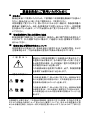
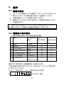
ファンクション・ジェネレータ FG-274 取扱説明書 お買い上げいただきましてありがとうございました。 ご使用の前に、この取扱説明書をよくお読みのうえ、 説明どおり正しくお使いください。 また、この取扱説明書は大切に保管してください。 © PRINTED IN CHINA B65-0241-18 保 証 について このたびは、当社計測器をお買上げいただきまして誠にありがとうございます。 ご使用に際し、本器の性能を十分に発揮していただくために、本説明書を最後までお読 みいただき、正しい使い方により、末永くご愛用くださいますようお願い申し上げます。 お買い上げの明細書(納品書、領収書等)は保証書の代わりとなりますので、大切に保 管してください。 サービスに関しましては、お買上げいただきました当社代理店(取扱店)にお問い合わ せくださいますようお願い致します。 なお、商品についてご不明な点がございましたら、当社の各営業所までお問い合わせく ださい。 保 証 当社計測器は、正常な使用状態で発生する故障について、お 買い上げの日より1ヵ年無償修理を致します。 保証期間内でも次の場合は有償修理になります。 1.火災、天災、異常電圧等による故障、損傷。 2.不当な修理、調整、改造がなされた場合。 3.取り扱いが不適当なために生ずる故障、損傷。 4.故障が本製品以外の原因による場合。 5.お買い上げ明細書類のご提示がない場合。 この保証は日本国内で使用される場合にのみ有効です。 ※ 本説明書中に マークが記載された項目があります。この マークは本器を使 用されるお客様の安全と本器を破壊と損傷から保護するために大切な注意項目です。 良くお読みになり正しくご使用ください。 目次 保証について 製品を安全にご使用いただくために ·······················································Ⅰ-Ⅳ 1. 特長.........................................................................................................1 2. 定格.........................................................................................................2 3. フロント・リアパネル..................................................................................5 3.1. フロント・パネル ............................................................................5 3.2. リア・パネル..................................................................................9 4. 操作...................................................................................................... 10 4.1. 機器の設定............................................................................... 10 4.2. 電源投入時の設定 .................................................................... 10 4.3. 出力の設定............................................................................... 11 4.4. 周波数の設定 ........................................................................... 11 4.5. 振幅と減衰器の設定 ................................................................. 12 4.6. DCオフセットの設定 .................................................................. 12 4.7. デューティ比の設定(方形波のみ) ............................................. 13 4.8. TTL/CMOS 出力...................................................................... 14 4.9. 設定の保存............................................................................... 15 4.10. 設定の呼出............................................................................... 16 4.11. 設定の消去............................................................................... 17 4.12. SHIFT キーとFunctions ........................................................... 17 4.13. エラーメッセージ ........................................................................ 18 製品を安全にご使用いただくために ■ はじめに 製品を安全にご使用いただくため、ご使用前に本説明書を最後までお読みく ださい。製品の正しい使い方をご理解のうえ、ご使用ください。 本説明書をご覧になっても、使い方がよくわからない場合は、取扱説明書の 裏表紙に記載された、当社・各営業所までお問い合わせください。本説明書 をお読みになった後は、いつでも必要なときご覧になれるように、保管してお いてください。 ■ 取扱説明書をご覧になる際のご注意 取扱説明書で説明されている内容は、説明の一部に専門用語も使用されて いますので、もしも理解できない場合は、ご遠慮なく当社・営業所までお問い 合わせください。 ■ 絵表示および警告文字表示について 本説明書および製品には、製品を安全に使用するうえで必要な警告、および 注意事項を示す、下記の絵表示と警告文字表示が表示されています。 < 絵 表 示 > 製品および取扱説明書にこの絵表示が表示されてい る箇所がある場合は、その部分で誤った使い方をす ると使用者の身体、および製品に重大な危険を生ず る可能性があることを表します。 この絵表示部分を使用する際は、必ず、取扱説明書 を参照する必要があることを示します。 <警告文字表示> 警 告 注 意 この表示を無視して、誤った使い方をすると、使用者が死亡 または重傷を負う可能性があり、その危険を避けるための 警告事項が記載されていることを表します。 この表示を無視して、誤った使い方をすると、使用者が軽度 の障害を負うか、または製品に損害を生ずる恐れがあり、 その危険を避けるための警告事項が記載されていることを 表します。 お客様または第三者が、この製品の誤使用、使用中に生じた故障、その他の不具合 またはこの製品の使用によって受けられた損害については、法令上の賠償責任が認 められる場合を除き、当社は一切その責任を負いませんので、あらかじめご了承くださ い。 I 製品を安全にご使用いただくために 警 告 ■ 製品のケースおよびパネルは外さないでください 製品のケースおよびパネルは、いかなる目的があっても、使用者は絶対に外 さないでください。使用者の感電事故、及び火災を発生する危険があります。 ■ 製品を使用する際のご注意 下記に示す使用上の注意事項は、使用者の身体・生命に対する危険、およ び製品の損傷・劣化などを避けるためのものです。必ず下記の警告・注意事 項を守ってご使用ください。 ■ 電源に関する警告事項 ●電源電圧について 製品は、定格電圧により『AC100V 専用モデル』と『AC115V/AC230V 切換モ デル』の2種類があります。必ず製品の定格電圧を確認し、付属の電源コー ドを使用してください。ただし、付属された電源コードが定格 AC125V仕様で、 製品の定格電圧を切り替えて AC125Vを超えた電源電圧で使用される場合 は電源コードの変更が必要になります。電源コードを AC250V 仕様のものに 変更しないで使用された場合、感電・火災の危険が生じます。 ●電源コードについて (重要) 同梱の電源コードセットは、本装置以外に使用できません。付属の電 源コードが損傷した場合は、使用を中止し、当社・営業所までご連絡くださ い。電源コードが損傷したままご使用になると、感電・火災の原因となること があります。 ●保護用ヒューズについて 入力保護用ヒューズが溶断した場合、製品は動作しません。ヒューズが溶断 した場合、使用者がヒューズを交換することができません。ヒューズ交換する には、製品のケースやパネルをはずす必要があります。お買上げいただきま した当社代理店(取扱店)または当社営業所までご連絡ください。 ●電源電圧の変更について 定格電源電圧が AC100V 専用の製品は、定格電源電圧の変更はできませ ん。定格電源電圧が AC115V/AC230V 切換の製品は、AC230V 又は AC115V に変更できます。(ただし、設定電圧に対応した電源コードを使用し てください。) 製品に表示された定格電源電圧以外での使用はしないでくだ さい。火災の危険があります。 II 製品を安全にご使用いただくために 警 告 ■ 接地に関する警告事項 製品には使用者の感電防止および製品保護のため、電源コードの保護用接 地導線をアースグラウンドに接続する必要があります。安全に使用するた め、必ず接地してからご使用ください。 ■ 設置環境に関する警告事項 ●動作温度について 製品は、定格欄に示されている動作温度の範囲内でご使用ください。製品の 通風孔をふさいだ状態や、周辺の温度が高い状態で使用すると、火災の危 険があります ●動作湿度について 製品は、定格欄に示されている動作湿度の範囲内でご使用ください。湿度差 のある部屋への移動時など、急激な湿度変化による結露にご注意ください。 また、濡れた手で製品を操作しないでください。感電および火災の危険があり ます。 ●ガス中での使用について 可燃性ガス、爆発性ガスまたは蒸気が発生あるいは貯蔵されている場所、お よびその周辺での使用は、爆発および火災の危険があります。このような環 境下では、製品を動作させないでください。また、腐食性ガスが発生または充 満している場所、およびその周辺で使用すると製品に重大な損傷を与えます ので、このような環境でのご使用はお止めください。 ●異物を入れないこと 通風孔などから製品内部に金属類や燃えやすい物などを差し込んだり、水を こぼしたりしないでください。感電および火災の危険があります。 ■ 使用中の異常に関する警告事項 製品を使用中に、製品より“発煙”“発火”などの異常を生じた場合は、ただち に使用を中止し、電源スイッチを切り、電源コードのプラグをコンセントから抜 いてください。他への類焼などがないことを確認した後、当社・営業所までご 連絡ください。 III 製品を安全にご使用いただくために 注 意 ■ 入出力端子について 入力端子には、製品を破損しないために最大入力の仕様が決められていま す。製品取扱説明書の“定格”欄、または“使用上のご注意”欄に記載された 仕様を超えた入力は供給しないでください。製品故障の原因になります。 また、出力端子へは外部より電力を供給しないでください。製品故障の原因 になります。 ■ 長期間使用しないとき 必ず電源プラグをコンセントから抜いておいてください。 《校正について》 製品は工場出荷時、厳正な品質管理のもと性能・仕様の確認を実施していま すが、部品などの経年変化などにより、その性能・仕様に多少の変化が生じ ることがあります。製品の性能・仕様を安定した状態でお使いいただくため、 定期的な校正をお勧めいたします。製品校正についてのご相談は、お買い上 げになりました取扱代理店または当社・各営業所へご連絡ください。 《日常のお手入れについて》 製品のケース、パネル、つまみ等の汚れを清掃する際は、シンナーやベンジ ンなどの溶剤は避けてください。塗装がはがれたり、樹脂面が侵されたりする ことがあります。ケース、パネル、つまみなどを拭くときは、中性洗剤を含ませ た柔らかい布で軽く拭き取ってください。 また、清掃のときは製品の中に水、洗剤、その他の異物などが入らないよう ご注意ください。製品の中に液体・金属などが入ると、感電および火災の原 因となります。清掃のときは電源プラグをコンセントから抜いてください。 以上の警告事項および注意事項を守り、正しく安全にご使用ください。 また、取扱説明書には個々の項目でも、注意事項が記載されていますので、 使用時にはそれらの注意事項を守り正しくご使用ください。 取扱説明書の内容でご不審な点、またはお気付きの点がありましたら、当社 の営業所までご連絡いただきますよう、併せてお願いいたします。 IV 1. 特長 FG-274 は、DDS(Direct Digital Synthesis)技術を使用したシンセサイズ ドファンクションジェネレータです。従来のアナログファンクションジェネレ ータは周囲温度の影響を受けやすく、温度変化によって抵抗・コンデンサ や他の部品の値が変化し、そのことで周波数が変化します。FG-274 は、 アナログ方式ではなく DDS 方式により、高精度・高安定度・高分解能を実 現しました。 z DDS 技術と FPGA を採用したことによる高品質な波形。 z 周波数高安定度、高精度: 20ppm。 z 低歪率: -55dBc。 z 最高出力周波数: 4MHz。 z 出力波形: 正弦波、方形波、三角波。 z 最高周波数分解能: 100mHz。 z TTL/CMOS 出力。 z DC オフセット機能。 z 設定メモリ機能。 1 2. 定格 1. メイン出力 出力波形 正弦波、方形波、三角波 周波数範囲 0.1Hz ~ 4MHz (正弦波、方形波) 0.1Hz ~ 1MHz (三角波) 周波数分解能 0.1Hz 周波数安定度 ±20ppm 周波数精度 ±20ppm エージング・レート ±5ppm/年 振幅範囲 10Vp-p (50Ω 負荷時) 出力インピーダンス 50Ω±10% 減衰器 -20dB±1dB × 2 段 DC オフセット範囲 ±5V 以上 (50Ω 負荷時) デューティ可変範囲 20% ~ 80% (1Hz~1MHz,方形波のみ) デューティ可変分解能 1% 表示 9 桁 LED 表示 2. 正弦波 歪率 (最大出力、ATT OFF、 TTL/CMOS OFF) -55dBc 以下 (0.1Hz ~ 200kHz) -40dBc 以下 (0.2MHz ~ 4MHz) 平坦性 ±0.3dB 以内 (0.1Hz ~ 1MHz) (最大出力、1kHz 基準) ±2.0dB 以内 (1MHz ~ 4MHz) 3. 三角波 直線性 2%以下 (0.1Hz ~ 100kHz) 5%以下 (100kHz ~ 1MHz) 4. 方形波 シンメトリ ±(周期の 1% + 4ns)以下(0.1Hz ~ 100kHz) 立上り/立下り時間 25ns 以下 (最大出力、50Ω 負荷時) 2 5. CMOS 出力 レベル 4V±1Vp-p ~ 14.5V±1Vp-p (連続可変) 立上り/立下り時間 120ns 以下 6. TTL 出力 レベル 3Vp-p 以上 ファンアウト 20 TTL 立上り/立下り時間 25ns 以下 7. 保存/呼出機能 メモリ数 10 セッティングメモリ 8. 設置環境 電源電圧 AC100V ± 10%、50/60Hz または AC115V/230V ± 10%、50/60Hz 定格消費電力 17W (21VA) ヒューズ (内蔵 ※1) T 0.250A/250V ×1 個(AC100V モデル) T 0.125A/250V ×2 個(AC115V/230V モデル) 動 作 環 境 使用環境 室内使用 高度 2,000m 以下 動作温度範囲 0℃ ~ 40℃ 仕様保証温度範囲 18℃ ~ 28℃ 相対湿度 80%以下 (0℃ ~ 35℃) 70%以下 (35℃ ~ 40℃) 設置カテゴリ II 汚染度 2 保存温度範囲 -10℃ ~ 70℃ 保存湿度範囲 70%以下 付属品 アクセサリコード (BNC-ワニグチ) ×1 取扱説明書 ×1 AC ケーブル ×1 最大寸法 266(W) × 97(H) × 293(D) mm 質量 約 3.1kg 3 9. 適合規格 EMC EN 61326-1: 1997+A1: 1998+A3: 2003 低電圧指令 IEC/EN 61010-1: 2001 ※1 ヒューズはお客様において交換することはできません。ヒューズ交 換するには、お買上げいただきました当社代理店(取扱店)または当社営 業所までご連絡ください。 【注意】電源の投入・遮断時、OUTPUT 端子から過渡的な出力(定格内) が出る場合があります。接続される機器の耐電圧にご注意ください。 【注意】方形波にて DUTY が 50%以外の時、シンメトリ規格の範囲内でジ ッタが発生する場合があります。 4 3. フロント・リアパネル 3.1. フロント・パネル ① POWER 主電源を ON/OFF するスイッチです。押し込むと電源が ON になり、 表示部が点灯します。 注: 電源の投入・遮断時、OUTPUT 端子から過渡的な出力(定格内)が 出る場合があります。接続される機器の耐電圧にご注意ください。 ② WAVE WAVE キーを押すとメイン出力の波形を選択できます。正弦波、 三角波、方形波と順次変わります。 出力している波形の LED⑥が点 灯します。 ③ 数値キー 各設定値入力用の数値キーです。 セカンダリ・ファンクション・キー SHIFT キーを押すと数値キーのセカンダリファンクションが有効に なります。各数値キーの上部に青文字で表記されています。 5 • • • • DEFAULT ( SHIFT + 2 (DEFAULT) ) は、デフォルトの 設定を呼び出します。 STORE ( SHIFT + 6 (STORE) ) は、10 個まで設定を保 存できます。(周波数、デューティ比、等) RECALL ( SHIFT + 3 (RECALL) )は、保存された設定 を呼び出します。 DUTY ( SHIFT + 7 (DUTY) ) は、方形波のデューティ比 を編集します。 注: 同じキー操作をするとオンとオフを繰り返します。 例えば、 SHIFT + 2 (DEFAULT) 定が呼び出されます。 キーを押すとデフォルトの設 ④ 単位キー 数値入力した場合の単位キーです。周波数設定の場合、 MHz kHz Hz/% のいずれかを押します。デューティ比では、 Hz/% を押してください。 ⑤ ロータリエンコーダ 入力数値を可変できます。 ◄ ► キーを押すことによって、入力 数値の可変させる桁を変更できます。時計方向に回すと増加し、反時 計方向で減少します。 ⑥ 波形 LED 波形の種類を表示する LED です。 ⑦ SHIFT キーLED SHIFT キーの状態を表示します。LED がオンなら、テンキーのセカ ンダリファンクションが有効です。 6 ⑧ 単位 LED 単位を表示する LED です。 ⑨ アッテネータ LED SHIFT + 8 (-20dB) キーで 20dB アッテネータを ON にすると点 灯します。AMPL ⑮ツマミをひいて 20dB アッテネータを ON にした場 合は点灯しません。 ⑩ DUTY LED DUTY LED が点灯しているときは、ディスプレイはデューティ比を表示 しています。編集待ち状態です(方形波のみ)。 ⑪ TTL/CMOS LED TTL/CMOS 出力がオンのとき、TTL LED が点灯します。(MAIN 出力 波形が方形波のときは、常にオンになります。) ⑫ 表示ユニット 周波数、デューティ比、設定・保存メモリなどの設定の表示をします。 ⑬ MAIN OUTPUT 出力インピーダンス 50Ω のメイン出力端子です。 ⑭ TTL/CMOS OUTPUT TTL/CMOS 出力端子です。 SHIFT + 9 (TTL) キーを押して、 TTL/CMOS 出力をオンにすると出力されます。TTL/CMOS ツマミ ⑰ を押した状態で TTL レベル、引いた状態で CMOS レベルになります。 CMOS レベルを可変するには、TTL/CMOS ツマミ ⑰を回してくださ い。 7 ⑮ AMPL レベル可変ボリュームです。ツマミを時計方向に回すと出力レベルが 増加し、反時計方向に回すと減少します。 ツマミを引くと 20dB アッテ ネータが入ります。このアッテネータでは、アッテネータ LED ⑨は点灯 しません。 ⑯ OFFSET DC オフセット調整ボリュームです。ツマミを引いて回すと、波形の DC オフセットを可変できます。可変範囲は、-5V から+5V です(50Ω 負荷 時)。時計方向にまわすと正方向に、反時計方向に回すと負方向にか わります。 ⑰ TTL/CMOS TTL/CMOS OUTPUT ⑭の TTL と CMOS の切換器です。 TTL/CMOS 出力がオンのとき、押した状態で TTL、引いた状態で CMOS です。CMOS の時に、つまみを回すとレベルを可変できます。 8 3.2. リア・パネル AC100V 専用モデル AC115V/230V 切換モデル ⑱ 電源入力コネクタ AC インレットです。付属の電源コードを接続してください。 ⑲ 電源切換器 115V/230V モデルの場合の、電源電圧切換器です。100V モデルに はありません。 9 4. 操作 4.1. 機器の設定 1) 2) 3) リア・パネルの電源セレクタを確認してください(AC115V/230V 切 換モデルのみ)。AC 電源が適切であることを確認してください。 付属の電源コードで AC 電源に接続してください。 電源をオンするとモデル名が表示され、工場出荷の設定にて出力 が開始されます。 注: 電源の投入・遮断時、OUTPUT 端子から過渡的な出力(定格内)が 出る場合があります。接続される機器の耐電圧にご注意ください。 4.2. 電源投入時の設定 工場出荷時の設定とメモリ初期化後の各設定 項目 工場出荷時 設定 4.12.1) “DEFAULT” 4.11 設定の消 去 1) 波形 2) 周波数 正弦波 ○ × 10.0000kHz ○ × 3) デューティ比 4) 20dB アッテネータ 50% ○ × OFF ○ × 5) TTL/CMOS 出力 6) カーソル位置 OFF 0.1Hz 桁 ○ × ○ × 7) STORE メモリ すべて “nuLL” ※ × ○ 電源 OFF 時の設定は、次回起動時に引き継がれます。 工場出荷時の設定に戻すためには、“DEFAULT”コマンドと“設定の消 去”をおこなってください。 《4.12.1) “DEFAULT“ ,4.11 ”設定の消去“を参照》 ※ メモリ内データ無し 10 4.3. 出力の設定 1) 2) WAVE キーを押すと出力波形を選択できます。キーを押す毎 に正弦波、方形波、三角波と変わります。波形に相当する LED ⑥ が点灯します。 方形波でパルス幅を変える場合は、デューティ比を設定してくださ い。 (『4.7 デューティ比の設定(方形波のみ)』を参照) 4.4. 周波数の設定 1) 2) 3) 4) ディスプレイ ⑫がデューティ比設定モードでないこと(DUTY LED がオフ)を確認してください。 設定する数値をテンキーで入力してください。 単位キーを選択してください。 さらに、 ◄ ► キーとロータリエンコーダ ⑤を使って、可変す ることもできます。 周波数の設定例 (1) (2) 250Hz に設定する場合… 2 5 0 Hz/% と押します。 850Hz に変更する場合… ◄ または ► を使って“2” の桁を 点滅させます。ロータリエンコーダ ⑤を時計方向に回して”8”に変更 します。 注: 1) 2) テンキー入力中は、 SHIFT + MHz (←) にてバックスペ ースが可能です。また、 SHIFT + kHz (CLEAR) にて数 値入力の全桁クリアが可能です。 テンキー入力中は、単位キー MHz , kHz , Hz/% を 押したときに設定が更新されます。一方、ロータリエンコーダで変 更中は常に設定が更新されます。 11 4.5. 振幅と減衰器の設定 1) 2) AMPL ⑮を回すとレベルを可変できます。 AMPL ⑮ツマミを引くと 20dB アッテネータが有効になります。 ま た SHIFT + 8 (-20dB) キーを押すと 20dB アッテネータが 有効になり、-20dB LED ⑨が点灯します。両方有効にすると 40dB になります。 注: 1) 2) -20dB LED ⑨は、 SHIFT + 8 (-20dB) の場合のみ点灯し ます。 20dB アッテネータをオフするときは、再度 SHIFT + 8 (-20dB) を押します。 4.6. DC オフセットの設定 1) 2) OFFSET ⑯ツマミを引くと、DC オフセット機能が有効になります。 DC オフセットの可変範囲は、-5V ~ +5V です。 つまみを時計方向に回すと DC レベルは正方向に、反時計方向に 回すと負方向に変化します。 注: 1) 2) オフセットを加えられた波形は、±20V(無負荷時) または±10V (50Ω 負荷時)に制限されます。波形振幅に対しオフセットが大き い場合は波形がクリップします。 20dB アッテネータをオンにすると、オフセット可変範囲も 20dB 小 さくなります。 12 4.7. デューティ比の設定(方形波のみ) 1) 2) 3) 注: SHIFT + 7 (DUTY) キーを押すとデューティ LED ⑩が点灯 します。 設定したいデューティ比の数値キーを押し、 Hz/% キーを押しま す。 デューティ比が設定され、周波数表示に戻ります。 さらに、 ◄ ► キーとロータリエンコーダ ⑤を使って、可変す ることもできます。( Hz/% キーを押すか、ロータリエンコーダを 止めて約 5 秒経過すると、周波数表示に戻ります。) 設定可能範囲外を入力した場合、またはテンキー入力中に Hz/% キーを押さなかった場合は、直前の有効な設定に戻り ます。 13 デューティ比の設定例 (1) (2) (3) (4) 注: 方形波のデューティ比を 60%に設定する場合。 SHIFT + 7 (DUTY) キーを押し、デューティ LED が点灯し たら、 6 0 Hz/% と押してください。 デューティ比を 30%に変更する場合。 ◄ または ► キーで “6”の桁を点滅させます。 それからロ ータリツマミ⑤を反時計方向に回して“3”に設定します。 ・デューティ比範囲: 20% ~ 80% ・周波数範囲: 1Hz ~ 1MHz (1Hz 未満を設定することができますが、デューティ比が 50%以 外の場合に 1Hz 未満を設定すると、DC 出力になり High または Low を出力します。) 4.8. TTL/CMOS 出力 BNC ⑭からTTL/CMOSレベルの信号を出力することができます。 TTL/CMOS出力の周波数は、メイン出力の周波数と同一です。周 波数を変更する場合は、『4.4 周波数の設定』 を参照ください。 1) SHIFT + 9 (TTL) キーを押します。TTL LED ⑪が点灯し、 TTL 出力がオンになり、BNC ⑭から出力されます。 2) TTL/COMS ツマミ ⑰を引き出すと CMOS 出力になります。BNC ⑭から CMOS レベルの信号が出力されます。TTL/COMS ツマミ ⑰を回して CMOS 信号のレベル調整をします。 注: 1) 2) TTL/CMOS 出力が ON の場合、メイン出力(正弦波と三角 波)に影響を与えます。正弦波と三角波で、TTL/CMOS 出力 を使わない場合には、OFF にしてください。 方形波を選択すると TTL/CMOS 出力は必ず ON になります。 14 TTL 出力の設定例 (1) (2) (3) (4) (5) 周波数: 5kHz、TTL 出力を設定する場合。 周波数を 5kHzに設定します。(4.4 周波数の設定参照) SHIFT + 9 (TTL) キーを押し、TTL/CMOS 出力モードにし ます。TTL LED ⑪が点灯します。 TTL/COMS ツマミ ⑰を押した状態にし、TTL モードにします。 5kHz の TTL レベルの信号が BNC ⑭から出力されます。 注: 1) TTL の場合、TTL/COMS ツマミ ⑰は、押し込んだままの状態 である必要があります。 2) TTL/COMS ツマミ ⑰が押し込んだ状態なら TTL、引かれてい たら CMOS の状態です。 CMOS 出力の設定例 (1) (2) (3) (4) (5) 周波数: 10kHz、CMOS 出力 10Vp-p を設定します。 周波数を 10kHzに設定します。(4.4 周波数の設定参照) SHIFT + 9 (TTL) キーを押し、TTL/CMOS 出力モードにし ます。TTL LED ⑪が点灯します。 TTL/COMS ツマミ ⑰を引き、CMOS モードにし、TTL/COMS ツ マミ ⑰を回して 10Vp-p になるように調整します。 10kHz の CMOS レベルの信号が BNC ⑭から出力されます。 4.9. 設定の保存 不揮発性メモリに設定パラメータを保存する機能です。メモリは、全 部で 0 から 9 までの 10 個あります。 1) SHIFT + 6 (STORE) キーを押します。ディスプレイ ⑫に “Store 0” と表示します。 (この状態で約 5 秒放置すると、周波数表示に戻ります。) 15 2) メモリ番号を 0 から 9 までの数字で入力します。 “done” と表示されたら保存動作は完了です。 設定の保存の例 (1) (2) メモリ番号 5 に設定を保存する場合。 SHIFT + 6 (STORE) キーを押し、 5 4.10. を入力します。 設定の呼出 不揮発性メモリに保存されたパラメータ(周波数と方形波のデューテ ィ比、等)を呼び出す機能です。 1) SHIFT + 3 (RECALL) キーを押します。 ディスプレイ ⑫に “recaLL 0”と表示されます。 2) (この状態で約 5 秒放置すると、周波数表示に戻ります。) 設定メモリナンバーを 0 から 9 までの数値で入力します。 “done” と表示されたら呼び出しは完了です。設定は、保存されて いた内容に変更されています。 設定呼出の例 (1) (2) メモリ 6 から設定を呼び出す場合。 まず SHIFT + 3 (RECALL) キーを押します。 次に を押します。 16 6 4.11. 設定の消去 不揮発性メモリに保存されたパラメータを消去する機能です。 1) 注: SHIFT + ◄ + ► + SHIFT + 8 + 4 + 2 + 6 + kHz のキーを順番に押し ます。メモリの消去が実行され、ディスプレイが周波数表示に戻り ます。 1) 2) 4.12. 不揮発性メモリの内容のみ消去します。現在の周波数・デュ ーティ比、等には影響ありません。 工場出荷時の状態に戻すためには、この不揮発性メモリ設定 の消去と併せて、デフォルト設定の呼び出しをする必要があ ります。 SHIFT キーと Functions SHIFT キーは、青字のセカンダリ機能を有効にします。 SHIFT キーを押すと “SHIFT LED” が点灯します。青字のキーだ けが有効になります。再度 SHIFT キーを押すと、解除されます。 セカンダリ機能 1) SHIFT + 2 (DEFAULT) デフォルト設定の呼出。 正弦波 10kHz、その他の設定はオフ。 2) SHIFT + 6 (STORE) 設定パラメータをメモリに保存。 3) SHIFT + 3 (RECALL) 設定パラメータをメモリから呼出。 4) SHIFT + 7 (DUTY) デューティ比入力モード。 5) SHIFT + 8 (-20dB) 20dB アッテネータの ON/OFF。 6) SHIFT + 9 (TTL) BNC⑭から出力される TTL また は CMOS レベルの信号の ON/OFF。 7) SHIFT + MHz (←) バックスペース。 8) SHIFT + kHz (CLEAR) 数値入力を全桁クリア。 17 4.13. エラーメッセージ エラーメッセージは、以下の通りです: エラーコード 説明 FrEq- Err1 周波数範囲外(正弦波、方形波) FrEq- Err2 周波数範囲外(三角波) FrEq- Err3 N/A FrEq- Err4 周波数分解能範囲外 duty- Err1 方形波以外でのデューティ比の設定 duty- Err2 周波数範囲外(デューティ比 50%以外での方形波) duty- Err3 デューティ比 範囲外(80%~20%) duty- Err4 デューティ比 分解能範囲外(1%) パネルでの表示は以下のようになります。 例:『FrEq- Err1』 例:『duty- Err1』 18 東京都町田市鶴間 1850-1 〒194-0004 http://www.texio.jp 仙 台 営 業 所 〒981-0914 仙台市青葉区堤通雨宮町 4-11 ℡ (022) 301-5881 北 関 東 営 業 所 〒360-0033 埼玉県熊谷市曙町 1-67-1 ℡ (048) 526-6507 首都圏第一営業所 〒194-0004 東京都町田市鶴間 1850-1 ℡ (042) 788-4821 首都圏第二営業所 〒194-0004 東京都町田市鶴間 1850-1 ℡ (042) 788-4822 名 古 屋 営 業 所 〒462-0853 名古屋市北区志賀本通 1-38 ℡ (052) 917-2340 大 阪 営 業 所 〒567-0868 大阪府茨木市沢良宜西 1-2-5 ℡ (072) 638-9695 サービスならびに商品に関するお問合わせは上記営業所をご利用ください。 FUNCTION GENERATOR FG-274 INSTRUCTION MANUAL © PRINTED IN CHINA B65-0241-18 CONTENTS USING THE PRODUCT SAFELY ·······················································Ⅰ-Ⅳ 1. FEATURES ........................................................................................ 1 2. SPECIFICATIONS ............................................................................. 2 3. FRONT AND REAR PANELS ........................................................... 5 3.1. Front Panel ............................................................................. 5 3.2. Rear Panel.............................................................................. 9 4. OPERATION .................................................................................... 10 4.1. The first time setup for the Instrument.................................. 10 4.2. Power-On Settings................................................................ 10 4.3. Output Setting....................................................................... 11 4.4. Frequency Setting................................................................. 11 4.5. Amplitude and Attenuation Setting ....................................... 12 4.6. Offset Setting ........................................................................ 12 4.7. Duty Cycle Setting (for square wave only) ........................... 13 4.8. TTL/CMOS Signal Output Function...................................... 14 4.9. STORE Setting ..................................................................... 17 4.10. RECALL Setting.................................................................... 17 4.11. DELETE Setting.................................................................... 18 4.12. SHIFT Key and Function Keys ............................................. 19 4.13. Error message of the instrument .......................................... 20 USING THE PRODUCT SAFELY ■ Preface To use the product safely, read this user's guide to the end. Before using this product, understand how to correctly use it. If you read this manual but you do not understand how to use it, call the company or each sales office that is indicated on the back cover of this user's guide. After you read this manual, save it so that you can read it anytime as required. ■ Notes on reading this user's guide The contents of this user's guide include technical terms in part of their explanation. If you do not understand those terms, do not hesitate to ask the company or each sales office. ■ Pictorial indication and warning character indication This user's guide and product show the warning and caution items required to safely use the product. The following pictorial indication and warning character indication are provided. <Pictorial indication> <Warning character Indication> WARNING CAUTION Some part of this product or the user's guide may show this pictorial indication. In this case, if the product is incorrectly used in that part, a serious danger may be brought about on the user's body or the product. To use the part with this pictorial indication, be sure to refer to this user's guide. If you use the product, ignoring this indication, you may get killed or seriously injured. This indication shows that the warning item to avoid the danger is provided. If you incorrectly use the product, ignoring this indication, you may get slightly injured or the product may be damaged. This indication shows that the caution item to avoid the danger is provided. I USING THE PRODUCT SAFELY WARNING ■ Do not remove the product's covers and panels Never remove the product's covers and panels for any purpose. Otherwise, the user's electric shock or a fire may be incurred. ■ Warning on using the product The warning items given below are to avoid danger to the user's body and life and avoid the damage and deterioration of the product. Use the product, observing the following warning and caution items. ■ Warning items on power supply ●Power supply voltage There are two kinds of products 'AC100V exclusive use model' and 'Change of AC115V/AC230V model' depending on the rated voltage. However, if the attached power cord is specified for a rating of AC125 V, and it is used at a power supply voltage exceeding AC125 V, it must be changed. If the power cord is not changed to one for AC250 V specification, an electric shock or fire may be incurred. ●Power cord Important: The attached power cord set can be used for this device only. If the attached power cord is damaged, stop using it and call the company or each sales office. If the power cord is used without the damage being removed, an electric shock or fire may be caused. ●Protection fuse If an input protection fuse is blown, the product does not operate. When the fuse is blown, the user cannot replace it. It is needed to remove the product's covers and rear panel, for changing a fuse. Contact to our distributor or to our sales office. ●Changing the power supply voltage When the rated power supply voltage is AC100V exclusive use, the rated power supply voltage cannot be changed. When the rated power supply voltage is AC115V or AC230V change, the rated power supply voltage can be changed to AC230V or AC115V. Use the product only at the rated power supply voltage indicated on the product. Otherwise, a fire may occur. (Please use the power supply code corresponding to a set voltage.) II USING THE PRODUCT SAFELY WARNING ■ Warning item on grounding The product has the GND terminal on the panel surface to protect the user from electric shock and protect the product. Be sure to ground the product to safely use it. ■ Warning item on installation environment ●Operating temperature Use the product within the operating temperature indicated in the rating column. If the product is used with the vents of the product blocked or in high ambient temperatures, a fire may occur. ●Operating humidity Use the product within the operating humidity indicated in the rating column. Watch out for condensation by a sharp humidity change such as transfer to a room with a different humidity. Also, do not operate the product with wet hands. Otherwise, an electric shock or fire may occur. ●Use in a gas Use in and around a place where an inflammable or explosive gas or steam is generated or stored may result in an explosion and fire. Do not operate the product in such an environment. Also, use in and around a place where a corrosive gas is generated or spreading causes a serious damage to the product. Do not use the product in such an environment. ●Do not let foreign matter in Do not insert metal and flammable materials into the product from its vent and spill water on it. Otherwise, an electric shock and fire may occur. ■ Warning item on abnormality while in use If smoke or fire is generated from the product while in use, stop using the product, turn off the switch, and remove the power cord plug from the outlet. After confirming that no other devices catch fire, call the company or each sales office. III USING THE PRODUCT SAFELY CAUTION ■ Input/output terminal Maximum input to the input terminals is specified to prevent the product from being damaged. Do not supply input, exceeding the specifications that are indicated in the "Rating" or "Caution on use" column in the user's guide of the product. Otherwise, a product failure is caused. Also, do not supply power to the output terminals from the outside. Otherwise, a product failure is caused. ■ When the product is left unused for a long time Be sure to remove the power plug from the outlet. (Calibration) Although the performance and specifications of the product are checked under strict quality control during shipment from the factory, they may slightly change because of secular changes in its parts. It is recommended to periodically calibrate the product so that it is used with its performance and specifications stable. For consultation about the product calibration, call the dealer or the company or each sales office where you bought the product. (Daily maintenance) When you clean off the dirt of the product covers, panels, and knobs, avoid solvents such as thinner and benzene. Otherwise, paint may peel off or the resin surface may be affected. To wipe off the covers, panels, and knobs, use a soft cloth with neutral detergent in it. During cleaning, be careful that water, detergents, and other foreign matters do not get into the product. If a liquid or metal gets into the product, an electric shock and fire are caused. During cleaning, remove the power cord plug from the outlet. Use the product correctly and safely, observing the above warning and caution items. Because the user's guide indicates caution items even in individual items, observe those caution items to correctly use the product. If you have questions or comments about the content of the user's guide, call the company's sales office. IV 1. FEATURES The FG-274 is Synthesized Function Generators which apply Direct Digital Synthesis (DDS) technique and can generate accurate and stable frequency with high resolution. The main signal source generate waveform including Sine wave, Square wave and Triangle wave. The main features are listed as follows: The design of DDS and FPGA technology provide high quality waveforms. High frequency stability and accuracy: 20ppm. Low Distortion at -55dBc. Wide output frequency range: 4MHz Digital operation user interface Output Waveforms of Sine, Square and Triangle. Maximum frequency resolution of full range: 100mHz. TTL/CMOS output Variable DC offset control Output overload protection Store/Recall function 1 2. SPECIFICATIONS 1. Main Output Output Function Sine, Square, Triangle Frequency Range 0.1Hz to 4MHz (For Sine, Square) 0.1Hz to 1MHz (For Triangle) Resolution Stability 0.1Hz ±20ppm Accuracy ±20ppm Aging ±5ppm/year Amplitude Range Impedance 10Vp-p (into 50Ωload) 50Ω±10% Attenuator -20dB±1dB ×2 DC Offset <-5V to >5V (into 50Ωload) Duty Control Range 20% to 80% (1Hz to 1MHz, for square wave only) Duty Control Resolution 1% Display 9-digit LED display 2. Sine Wave Harmonics Distortion From Amplitude control at maximum position without any attenuation to its 1/10 of any combination setting, TTL/COMS off. ≦-55dBc, 0.1Hz to 200kHz ≦-40dBc, 0.2MHz to 4MHz Flatness(at the maximum <±0.3dB, 0.1Hz to 1MHz amplitude relating to <±2.0dB, 1MHz to 4MHz 1kHz) 3. Triangle Wave Linearity ≦2%, 0.1Hz to 100kHz ≦5%, 100kHz to 1MHz 2 4. Square Wave Symmetry Rise or Fall Time ±(1% of period + 4ns) to 0.1Hz to 100kHz ≦25ns at maximum output. (into 50Ωload) 5. CMOS Output Level Rise or Fall Time 4V ± 1Vp-p to 14.5V ± 1Vp-p , adjustable ≦120ns 6. TTL Output Level ≧3Vp-p Fan Out 20 TTL load ≦25ns Rise or Fall Time 7. Store/Recall Function Size 10 groups of setting memories 8. General Power Source AC100V ± 10%, 50/60Hz or AC115V/ 230V ± 10%, 50/60Hz Ratings Power Consumption 17W (21VA) FUSE (built-in ※1) T 0.250A/250V x1 (AC100V model) T 0.125A/250V x2 (AC115V/230V model) Indoor use Altitude: up to 2000m Operating temperature: 0℃ to 40℃ Operation Environment (+32oF to +104oF) Temperature to satisfy the specification: 18℃ to 28℃ (+64.4oF to +82.4oF) Relative Humidity: Up to 80% at 0 to 35 ℃, Up to 70% at 35 to 40℃ Installation Category II Pollution Degree 2 3 o o Storage Temperature & -10℃ to 70℃. (+14 F to 158 F) Humidity 70% (Maximum). Accessory code (BNC-ALLIGATOR) ×1 Instruction manual ×1 Accessories AC cable ×1 Dimension 266(W) × 97(H) × 293(D) mm Weight Approx. 3.1kg 9. Regulation EMC EN 61326-1: 1997+A1: 1998+A3: 2003 Safety IEC/EN 61010-1: 2001 ※1 When the fuse is blown, the customer cannot replace it. Contact to our distributor or to our sales office, for changing a fuse. 【 note 】 Please pay attention to electric strength of connected equipment. A transitional output (in ratings) might go out of the terminal OUTPUT, when power supply is turned on and turned off. 【note】 With square wave, jitter might be generated within the range of the specification of symmetry, except 50% duty cycle. 4 3. FRONT AND REAR PANELS 3.1. Front Panel ① POWER button: Power on/off the instrument by pressing the button with the display on/off. Note: Please pay attention to electric strength of connected equipment. A transitional output (in ratings) might go out of the terminal OUTPUT, when power supply is turned on and turned off. ② Main Function keys: Press WAVE key to select main output waveform in the sequence of Sine, Triangle and Square. When the key is pressed, the corresponding waveform LED ⑥ will light. ③ Entry keys: Press 0 to 9 and . keys to input value, then press a valid Units key to complete the setting. 5 Secondary Function keys: The secondary function keys are activated by the combinations of SHIFT key and numerical keys labeled in blue. • DEFAULT ( SHIFT + 2 (DEFAULT) ) will set this • instrument to the default setup. STORE ( SHIFT + 6 (STORE) • frequency and duty cycle setting up to 10 memories. RECALL ( SHIFT + 3 (RECALL) ) can recall the setup • stored in this instrument. DUTY ( SHIFT + 7 (DUTY) ) allows to store ) allows to edit the duty cycle of square wave. Note: The other functions are toggled between ON and OFF by repeating the same key combination operation. For example, press SHIFT + 2 (DEFAULT) keys can recall the default value of the instrument. ④ Units keys: Select one of the valid Units keys (MHz, kHz, Hz) MHz kHz Hz/% for the entered value of frequency and duty cycle (Hz/%). ⑤ Modify keys: Press ◄ ► keys to shift the digit of input value. Rotate the knob for increasing or decreasing that digit. ⑥ Waveform LEDs: To indicate the current waveform of the main output. 6 ⑦ SHIFT key Status LED: To indicate the SHIFT key status. When this LED is on, the following numerical keys will be activated as the secondary function keys. ⑧ Units LEDs: To indicate the units of frequency or duty cycle. ⑨ Attenuator LED: When the -20dB LED is on, the –20dB attenuator is controlled by the SHIFT + 8 (-20dB) keys are on. ⑩ DUTY LED: When the DUTY LED is on, the parameter display will show the duty cycle and wait for editing (for square wave only). ⑪ TTL/CMOS LED: When the TTL LED is on, that means the TTL/CMOS is enabled. (Always turn on when the MAIN output wave form is a square wave.) ⑫ Parameter display: The 9 digits parameter display presents the parameter values and information, like counter frequency, duty cycle and save/recall. ⑬ MAIN Output Main output with 50Ω output resistance. 7 ⑭ TTL/CMOS Output Press SHIFT + 9 (TTL) keys, a TTL compatible waveform will be obtained from the output by pushing back and rotating the TTL/CMOS knob ⑰, and a CMOS compatible waveform (5Vp-p to 15Vp-p) will be obtained from the output while the TTL/CMOS knob is pulled out and rotated. ⑮ Output Amplitude Control with Attenuation operation Turn the knob clockwise for increasing output level and invert for decreasing. Pull the knob out for an additional 20dB output attenuation. This attenuation will not change the LED status. ⑯ DC Offset Control Pull out the knob to turn the DC offset of the waveform between –5V to +5V (into 50Ω load), turn the knob clockwise to set a positive going DC level waveform and turn reversely for a negative going DC level waveform. ⑰ TTL/CMOS Selector When the TTL/CMOS output is turn on, push back this knob to select the TTL as the output and pull out this knob to select CMOS. When the CMOS is selected, rotate the knob to set the CMOS level. 8 3.2. Rear Panel AC100V exclusive use model AC115V/230V change model ⑱ Power Entry Socket AC input should be within the range of line voltage ±10%, 50/60Hz. ⑲ Line Voltage Selector To switch the power line voltage between AC115V and AC230V. 9 4. OPERATION 4.1. The first time setup for the Instrument 1) Ensure that the voltage of main supply is compatible with this instrument. The selector on the rear panel states the required AC line voltage. (Only AC115V/230V change model) 2) 3) Connect the instrument to main supply with the power cord. Turn on the instrument, the model number will show up on the parameter display area first, then, the output is started by the factory default setting. Note: Please pay attention to electric strength of connected equipment. A transitional output (in ratings) might go out of the terminal OUTPUT, when power supply is turned on and turned off. 4.2. Power-On Settings Setting when factory is shipped and after initializing the memory Item factory default settings 4.12.1) 4.11 “DEFAULT” DELETE Setting command ○ × 1) Wave form Sine 2) Frequency 10.0000kHz ○ × 3) Duty cycle 50% ○ × 4) 20dB ATT OFF ○ × 5) TTL/CMOS output OFF ○ × 6) Cursor position 0.1Hz digit All “ nuLL ” ※ ○ × × ○ 7) STORE memory When being turn on next time, the setting at turn off is succeeded. 10 For reset setting ,when factory is shipped. Execution DEFAULT command and Initializing the memory. 《Please refer to 4.12.1) “DEFAULT” ,4.11 DELETE Setting》 There is no data in the memory. ※ 4.3. Output Setting 1) Press WAVE key to select main output waveform. The waveform will be changed in the sequence of Sine, Square and Triangle waveform every time when the key is pressed, and the corresponding waveform LED ⑥ will light. 2) Set different duty cycle (not 50%) for Square waveform to get different Pulse width of the waveform (Please refer to 4.7 Duty Cycle Setting (for square wave only)). 4.4. Frequency Setting 1) Ensure that the Parameter display ⑫ is not in the Duty Cycle Setting mode, the DUTY LED ⑩ is off. 2) 3) 4) Key in the desired value of frequency. Select a valid Unit key for the value. In addition, you can use ◄ ► keys and rotating the knob ⑤ to adjust the desired main frequency value. Example of the Frequency Setting (1) (2) Set the frequency to 250Hz. Press 2 5 0 and Hz/% . Change the frequency to 850Hz. Press ◄ or ► to shift the flashing digit to “2” position, then change the digit to “8” by rotating the knob ⑤ clockwise. 11 Note: 1) The back space is possible, while inputting ten keys. Press SHIFT + MHz (←) . And Press 2) SHIFT + kHz (CLEAR) when all digits input can clear. To be inputting ten keys is to push the unit key kHz , Hz/% , the setting is updated. MHz , On the other hand, The setting is always updated while changing with the rotary encoder. 4.5. Amplitude and Attenuation Setting 1) 2) Rotate AMPL ⑮ to control demanded output level. Pull out AMPL ⑮ knob to get 20dB attenuation and press SHIFT + 8 (-20dB) keys can obtain an additional 20dB attenuation. Now, the -20dB LED ⑨ will light. It becomes 40dB when both keeping effective. Note: -20dB LED ⑨ is responding to SHIFT + 8 (-20dB) 1) attenuator only. 2) The functions are toggled between ON and OFF by repeating the to SHIFT + 8 (-20dB) keys operation. 4.6. Offset Setting 1) 2) Pull out the OFFSET ⑯ knob to activate the DC offset function, which allows to adjust the DC level of the waveform between -5V to +5V. Rotate the knob clockwise to set a positive going DC level waveform and invert for a negative going DC level waveform. 12 Note: 1) 2) However, signal added DC level is still limited to ±20V (no load) or ±10V (50Ω load). In case of over-voltage, the clip of waveform will appear as shown below. If 20dB attenuator is turned on, the range of the offset changeability becomes small 20dB, too. 4.7. Duty Cycle Setting (for square wave only) 1) Press 2) is on. Key in the desired value of Duty cycle, then press 3) SHIFT + 7 (DUTY) keys until the DUTY LED ⑩ Hz/% key to specify the value. Then the parameter display will return to display frequency. In addition, you can use ◄ or ► keys and rotate the knob ⑤ to change the desired Duty cycle as well. Note: Any incomplete entry of the duty cycle will last for 5 seconds, then return to previous setting. 13 Example of the Duty cycle Setting (1) (2) Set the Square wave Duty cycle to 60%. Press SHIFT + 7 (DUTY) keys, DUTY LED ⑩ is on, then press (3) (4) 6 0 Hz/% . Change the Duty cycle to 30%. Use ◄ or ► key to shift the flashing digit to “6” position, then change the digit to “3” by rotating the knob ⑤ counterclockwise. Note: The duty cycle limit : 20%~80%. The frequency limit : 1Hz~1MHz. (Though less than 1Hz can be set, It becomes DC output and High or Low is output. When you set less than 1Hz things except every 50% it compared with the duty cycle.) 4.8. TTL/CMOS Signal Output Function This product provide a TTL/CMOS signal from Output ⑭. The frequency of TTL/CMOS output is identical to the main output frequency. If the frequency needs to be modified, please refer to 4.4 Frequency Setting. 1) Press SHIFT + 9 (TTL) button, The TTL LED ⑪ will 2) light to indicate that the TTL output function is activated and a compatible TTL level signal will be obtained from TTL/CMOS Output BNC connector ⑭. Pull out TTL/COMS knob ⑰, the CMOS output function is activated, then a compatible CMOS level signal will be obtained from TTL/CMOS Output BNC connector ⑭. Turn the TTL/COMS knob ⑰ to adjust to the desired CMOS signal level. 14 Note: 1) The main output waveform (Sine and Triangle wave) quality will be affected when TTL/CMOS is activated. So when a high quality Sine or Triangle wave is required, please turn off this function. 2) When you choose square wave, the TTL/CMOS function will always be activated. Example of the Setting of the TTL Output (1) (2) To set the instrument: • Frequency: 5kHz • Signal type: TTL output Proceed the following steps: • Set the main frequency to 5kHz (refer to the Setup of Frequency). • Press SHIFT + 9 (TTL) keys to set TTL/CMOS output mode. The TTL LED ⑪ is on now. • A 10kHz/TTL Level signal will be obtained from the connector ⑭. Note: 1) Now the TTL/CMOS knob ⑰ is in the push back status. 2) The functions are toggled between TTL and CMOS by repeating the TTL/CMOS knob operation. 15 Example of the Setting of the CMOS Output (1) (2) (3) (4) (5) To set the instrument: • Frequency: 10kHz , Signal type: 10Vp-p CMOS output Set the main frequency to 10kHz (refer to 4.4 Frequency Setting). Press SHIFT + 9 (TTL) keys to set TTL/CMOS output mode. The TTL LED ⑪ is on now. Pull out and turn the TTL/COMS knob ⑰ to adjust the CMOS signal level to 10Vp-p. A 10kHz/CMOS Level signal will be obtained from the connector ⑭. 16 4.9. STORE Setting The Store function allows to save the setup parameters (Frequency value and Duty cycle for square wave) of the instrument into its nonvolatile memory with the stored group number from 0 to 9, up to 10 groups totally. 1) Press SHIFT + 6 (STORE) keys, the message of “Store 0” will present on the parameter display ⑫. (Then the parameter display will return to display frequency. when leaving it for about five seconds.) 2) Key in the group number from 0 to 9 . The message of “done” will present to complete the store function. Example of the STORE Setting (1) (2) To save the parameters to the group 5. Press SHIFT + 6 (STORE) keys first, then key in 4.10. 5 . RECALL Setting The Recall function allows to retrieve the parameters (Frequency value and Duty cycle for square wave) saved in the nonvolatile memory. 1) Press SHIFT + 3 (RECALL) keys, the message of “Recall 0” will present on the parameter display ⑫. (Then the parameter display will return to display frequency. when leaving it for about five seconds.) 17 2) Key in the group number from 0 to 9 . The message of “done” will present to complete the recall function. The setting should be changed accordingly. Example of the Setting of the RECALL (1) (2) To retrieve the parameters from the group 6. Press SHIFT + 3(RECALL) keys first, then key in 4.11. 6 . DELETE Setting The Delete function allows to delete the parameter preserved in the nonvolatile memory. 1) Press SHIFT + ◄ + ► + SHIFT + 8 + 4 + 2 + 6 + kHz keys sequentially, the deletion of the memory is executed, and the display returns to the frequency. Note: 1) 2) Only the content of the nonvolatile memory is deleted. There are no influences in a present frequency and the duty cycle, etc. To return it to the state when the factory is shipped, the “Recall the default state of the instrument” along with “Delete Setting” should execute. 18 4.12. The SHIFT Key and Function Keys SHIFT key is used to enable the secondary functions of certain function keys with blue printed letters. After pressing the button, the SHIFT LED ⑦ will light, only the keys labeled in blue are activated. Press SHIFT key again to release the secondary function. The Secondary Functions SHIFT + 2(DEFAULT) 1) Recall the default state of the instrument. The default state is defined as sine wave and 10kHz, all other functions are off. 2) SHIFT + 6 (STORE) Store the parameters (Frequency and Square wave duty cycle, etc.) to memory. 3) SHIFT + 3 (RECALL) Retrieve the parameters (Frequency and Square wave duty cycle, etc.) from memory. 4) SHIFT + 7 (DUTY) To get into Square wave Duty cycle enter mode. 5) SHIFT + 8 (-20dB) The 20dB attenuation is activated. 6) SHIFT + 9 (TTL) The TTL or CMOS level signal will output from the BNC ⑭. 7) SHIFT + MHz (←) Backspace. 8) SHIFT + kHz(CLEAR) A numeric input is cleared in all digits. 19 4.13. Error message of the instrument The error message shows up when the illegal entry is performed. The categories of the error message is listed as the following table: Error Code Explanation (Limitation) FrEq- Err1 Sine and Square wave Frequency over range. FrEq- Err2 Triangle wave Frequency over range (1MHz). FrEq- Err3 N/A FrEq- Err4 Frequency over Resolution duty- Err1 Not Square Waveform. duty- Err2 Square wave Frequency over range when duty cycle is not 50:50 (1MHz) duty- Err3 Duty cycle over range (80:20) duty- Err4 Duty cycle over resolution (1%) The display with the panel is as follows. Example:『FrEq- Err1』 Example:『duty- Err1』 20 1850-1, Tsuruma, Machida-shi, Tokyo, 194-0004 Japan http://www.texio.jp