1
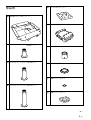
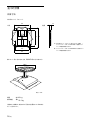
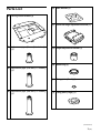
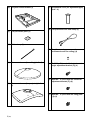
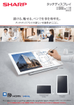
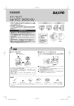
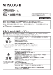
4-100-804-02(1) Projector Suspention Support プロジェクターサスペンションサポート 特約店様用取付説明書 お買い上げいただきありがとうございます。この取付説明書は、特約店様用に書かれたも のです。 お客様へ 本製品の取り付けには、確実な作業が必要になります。必ず、販売店や工事店に依頼 して、安全性に充分考慮して確実な取り付けを行ってください。 安全のための注意事項を守らないと、火災や人身事故になることがあります。 この説明書には、事故を防ぐための重要な注意事項と製品の取り扱い かたを示してあります。この説明書をよくお読みのうえ、製品を安全 にお使いください。お読みになったあとは、いつでも見られるところ に必ず保管してください。 特約店様へ 本製品の取り付けには特別な技術が必要ですので、設置の際には取付 説明書をよくご覧の上、設置を行ってください。取り付け不備や取り 扱い不備による事故、損傷については、当社では責任を負いません。 なお、この取扱説明書は、取り付け作業後にお客様に渡してくださ い。 このプロジェクターサスペンションサポートはプロジェクター専用で す。プロジェクター以外の機器には使わないでください。 Installation Manual for Dealers PSS-100 2003 Sony Corporation 1 (JP) 耐用荷重:最大 47.5 kg PSS-100はソニーのプロジェクター用の天井吊り下げ用サス 目次 ペンションサポートです。 スクリーンサイズと投射距離および天井からプロジェクター までの距離など、設置寸法については、プロジェクター本 体の取扱説明書または設置説明書をご覧ください。 ................................................................................ 3 ................................................................................ 4 部品表 ................................................................................. 5 Q004-R1取り付け時の寸法 .............................................. 8 天井への取り付け例 ............................................................ 9 板天井に取り付ける場合 ................................................. 9 コンクリート天井に取り付ける場合 ................................... 9 安全のために 天井への取り付けかた ...................................................... 10 天井用マウントブラケットの組み立てかた ..................... 10 天井への取り付けかた .................................................. 11 警告表示の意味 取扱説明書および製品では、次のような表示をしています。 表示の内容をよく理解してから本文をお読みください。 調整のしかた .................................................................. 13 飾りカバーを取り付ける(Q004-R1 取り付け時のみ)... 14 主な仕様 ............................................................................ 16 外形寸法 ........................................................................ 16 この表示の注意事項を守らないと、火災や感電などにより死 亡や大けがなど人身事故につながることがあります。 この表示の注意事項を守らないと、感電やその他の事故によ りけがをしたり周辺の物品に損害を与えたりすることがありま す。 注意を促す記号 行為を禁止する記号 行為を指示する記号 2 (JP) 設置は専門の工事業者に依頼する 設置については、必ずお買い上げ店にご相談く 火災 感電 ださい。 天井への設置は、 プロジェクターと取り付け金具 下記の注意を守らないと、 を含む重量に充分耐えられる強度があることを 火災や感電により死亡や大けがにつなが お確かめください。充分な強度がないと、落下 ることがあります。 して、大けがの原因となります。 また、1年に1度は、取り付けがゆるんでいない ことを点検してください。 製品の落下による死亡、大けがなどの事故を 避けるため、下記の注意事項を必ずお守りく ださい。 ・ 設置については、お買い上げ店にご依頼くだ さい。 ・ 天井は少なくとも300 kgの重量を支えられるよ うに、必要に応じて補強を行ってください。 分解や改造をしない 分解や改造をすると、火災や感電、けがの原因 となることがあります。 内部の点検や修理は、お買い上げ店にご依頼く ださい。 ・ブラケットを天井に直接取り付ける場合には、 天井に合わせて、市販のM10ボルトとナット、 ワッシャーをご使用ください。M10以外のボル 設置場所の移動は、設置業者に依頼する ト、ナット、ワッシャーで取り付けると落下する お客様による設置場所の移動は、火災や人身 危険があります。 事故につながることがあります。設置場所の移 ・ 取り付けは手順に従ってください。手順に従 わないと落下する危険や、死亡・大けがにつ 動は、お買い上げ店または、専門の設置業者に ご依頼ください。 ながることがあります。 ・ PSS-100はソニーのプロジェクターの天井吊り 下げ用サスペンションサポートです。 それ以外 の用途には使用しないでください。 2人以上で運搬する 本機は重量物ですので、1人で運搬すると腰を 痛めたり、けがをすることがあります。 3 (JP) 下記の注意を守らないと、 けがをしたり周辺の物品に損傷を与えるこ とがあります。 取り付け時にネジを確実に締める ネジの締め付けが不充分な場合、本機が落下 し、けがをする原因となることがあります。 不安定な場所で設置作業を行わない 不安定な場所で設置作業を行わないでくださ い。腰を痛めたり、プロジェクターが落下したり して大けがの原因となります。 レンズをのぞかない プロジェクターの調整中や投影中にプロジェク ターのレンズをのぞくと、強い光が目に入り、目 に悪影響を与えることがあります。 ぬれた手で電源プラグをさわらない ぬれた手で電源プラグを抜き差しすると、感電 の原因となることがあります。 4 (JP) 部品表 (E) ベースブラケット(1) (F) 水平角度調整ブラケット(1) (A) 天井用マウントブラケット(1) (B) アジャストメントパイプ(69 mm)(1) (G) 高さ調整ブラケット(1) (C) アジャストメントパイプ(119 mm)(1) (H) スリーブリング(1) (D) (I) 固定プレート(小)(1) (J) 固定プレート(大)(1) アジャストメントパイプ(169 mm)(1) (続く) 5 (JP) (K) プロジェクター用マウントブラケット(1) (P) 飾りカバー (アジャストメントパイプ用) (半径×4) (Q) 落下防止ワイヤーとワイヤークランプ (2) (L) 落下防止プレート(2) (M) ケーブルクランプ(2) (R) キャップ (天井側飾りカバーネジ用)(4) (N) 飾りカバー(天井側)(半径×2) (a) ボルトM6×25 (水平角度調整ブラケット[F] 用)(4) (b) ボルトM6×10 (水平角度調整ブラケット[F] 用)(4) (O) 飾りカバー(プロジェクター側)(半径×2) (c) 6 (JP) ボルトM8×12 (固定プレート[J] 用)(4) (d) ボルトM8×8 (高さ調整ブラケット [G] 用) (4) ご注意 プロジェクターサスペンションサポートPSS-100を取り付けるときは 本機に付属のネジ、ボルトを使用し、他のネジやボルトは使用しな いでください。 また、ネジなどを締めすぎた場合、プロジェクターの 取り付け部分が破損することがありますのでご注意ください。 (e) ネジM4×6 (高さ調整ブラケット [G]用)(4) (f) ネジPSW4×12 (固定プレート [I] 用/落下防 、[O] 用/ 止プレート [L]用/飾りカバー[N] 落下防止ワイヤー [Q] 用)(16) (g) ボルトM8×20 (水平角度調整ブラケット [F] 用)(4) (h) 段付きボルト(4) (i) 段付きボルト用ワッシャー(4) 7 (JP) Q004-R1取り付け時の寸法 上面図 プロジェクターのレンズの中心とスクリーンの中心が合うように設置してください。 254 ケーブル配線用天井穴 Ø70 254 スクリーン中心 レンズ中心 支柱中心 天井用マウントブラケット 取付穴(4ヶ所) 52.5 天井用マウントブラケット 前面図 側面図 200.5 254 127 254 天井 天井 (P) h プロジェクター用マウント ブラケット取り付け面 105 レンズ前面 285 レンズ中心 327.5 支柱中心 キャビネット前面 h = 天井からプロジェクター用マウントブラケット取り付け面までの距離 アジャストメントパイプ (B) 使用時:150∼200 mm アジャストメントパイプ (C)使用時:200∼250 mm アジャストメントパイプ (D)使用時:250∼300 mm 8 (JP) 425.5 支柱中心 単位:mm 天井への取り付け例 以下は、サスペンションサポートが天井に取り付けられたときの 様子を示します。天井の材質によって補強方法が異なります。 ご注意 取り付ける前に天井の最大耐用荷重が 300kg 以上あることをお確かめください。 板天井に取り付ける場合 平屋または最上階の場合 補強材 254 梁 (5×20 cm) 254 127 くぎ 天井 ナットとワッシャーで締めたM10ボルト 天井用マウントブラケット 支柱中心 その他の階の場合 上の階の床 254 梁 254 梁(5×20 cm) 127 天井 ナットとワッシャーで締めたM10ボルト 天井用マウントブラケット 支柱中心 コンクリート天井に取り付ける場合 254 コンクリート天井 127 天井用マウントブラケット コンクリートアンカー(12mm径以上) 壁端から80mm以上距離をとってください。 支柱中心 単位:mm 9 (JP) 天井への取り付けかた 4 高さ調整ブラケットを取り付けたアジャストメントパイプを逆向き にして、天井用マウントブラケット (A)にまっすぐにねじ込む。 天井用マウントブラケットの組み立て かた 1 (A) アジャストメントパイプ(B)/(C)/(D)を選ぶ。 本機を使用してプロジェクターを吊り下げる場合、スクリーン の上面とレンズの中心が合うように設置します。スクリーンと 天井の高さに応じて3本のアジャストメントパイプから適当な長 さのものを選んでください。 ご使用になるアジャストメントパイプによって、天井取り付け面 からプロジェクター用マウントブラケット取り付け面までの距離 は以下のようになります。(それぞれ50mmの範囲で調整可能 です。) アジャストメントパイプ(B)使用時:150 ∼ 200 mm アジャストメントパイプ(C)使用時:200 ∼ 250 mm アジャストメントパイプ(D)使用時:250 ∼ 300 mm 2 5 固定プレート(I)をパイプの中で固定する。 ネジPSW4×12(f) (2 本)で固定します。 (f) 使用するアジャストメントパイプ(B)/(C)/(D)の、内側に ネジの切ってあるほうを上にして置き、スリーブリング(H) 、 (I) ベースブラケット(E)の順にアジャストメントパイプにはめる。 (E) (H) (B)/(C)/(D) 3 高さ調整ブラケット (G) をアジャストメントパイプに取り付ける。 ネジM4×6(e) (4 本)で固定します。 ボルトM8×8(d) (4本)は仮止めします。あとで高さを調整 します。 (d) (e) (e) (d) (e) (d) (d) (G) (e) (E) (H) 10 (JP) 固定プレート(I) は、落下防止のための重要 な部品です。このプレートが固定されていない と、あとでプロジェクターの高さを調整すると きに調整範囲を越えても止まらないため、プロ ジェクターが落下する恐れがあります。必ず固 定プレートを取り付け、確実に固定してくださ い。 6 ベースブラケット(E)を上まで引き上げ、固定プレート(J)を ベースブラケットに仮止めする。 ボルトM8×12(c) (4本)を使用します。あとで高さを調整し 天井への取り付けかた 1 上記1∼7で組み立てた天井用マウントブラケットを天井に取 り付ける。 ます。 (J) 市販の M10 埋め込みボルト、ワッシャー、スプリングワッ シャー、ナット (4ヶ所)をご使用ください。これらの部品は、お (E) 客様でご用意ください。 埋め込みボルトは天井用マウントブラケット取付面から20 mm 出るようにしてください。 「天井への取り付け例」 (9ページ) を 参考に取り付けてください。 (c) (c) M10ボルト 20mm 7 天井用マウントブラケット(A)が上になるように裏返し、水平 スクリーン方向 角度調整用ブラケット(F)をベースブラケット(E)にはめ込 む。 ボルトM6×25(a) (4本) 、M6×10(b) (4本)で固定します。 (A) ワッシャー スプリングワッシャー ナット (A) Q004-R1への取り付け例 (F) 天井用マウントブラケット (E) 埋め込みボルト、 ワッシャー、スプリング ワッシャー、ナット 20mm (a) (b) (b) (a) ボルト M6×25(a)およびM6×10(b)は、 落下防止のための重要な部品です。作業は確実 に行ってください。 (続く) 11 (JP) 2 プロジェクターを裏返し、プロジェクター用マウントブラケット (3) ワイヤーの先端部を、ネジPSW4×12(f) (2 本)を使用 してプロジェクター用マウントブラケット(A)に固定する。 (K)を取り付ける。 段付きボルト(h) (4 本)と段付きボルト用ワッシャー(i) (4 本)を使用します。 (h) (h) (i) (i) (K) (h) (h) (i) (A) (i) (f) もう一方のアジャスターにも同様に落下防止ワイヤーをしっか り取り付け、ネジ止めします。 ご注意 ワイヤークランプは、 アジャスターの根元までしっかりと締め付 けてください。 段付きボルト(h)は、落下防止のための重要 な部品です。作業は確実に行ってください。 4 ご注意 ・ 取り付けの際に、ボルトをきつく絞めすぎないように注意し プロジェクターに取り付けたプロジェクター用マウントブラケッ ト(K)を、天井用マウントブラケットのフックに引っ掛ける。 てください。 ・ プロジェクターや机に傷がつかないよう布などを敷いた上 で作業を行ってください。 3 プロジェクターに落下防止ワイヤーを取り付ける。 (1) プロジェクターのアジャスターに落下防止ワイヤー(Q)を しっかりと引っ掛ける。 (2) 落下防止ワイヤーをワイヤークランプでしっかり締める。 (K) (Q) ワイヤークランプ アジャスター 12 (JP) 5 プロジェクター用マウントブラケットを天井用マウントブラケット 調整のしかた に左右4か所で仮止めする。 ボルトM8×20(g) (4本)を使用します。あとで、プロジェク 設置条件によって、プロジェクター底面と天井の角度や、 プロジェ ター底面と天井の角度を調整します。 クターの高さなどを調整できます。 他の機器との接続を行い、プロジェクターの電源コードをコンセン トに差し込みます。プロジェクターの電源を入れ、接続した機器か (g) らの映像を映して調整します。 プロジェクターの高さを調整する 図(d)の高さ調整ブラケット用ボルト4 本をゆるめ、高さ調整ブラ ケットを回して調整します。時計回りに回すと、プロジェクターが下 (g) がり、反時計回りに回すと、上がります。 天井取り付け面からプロジェクター用マウントブラケット取り付け面 まで、50 mm の範囲で調整できます。 6 アジャストメントパイプ(B)使用時:150∼ 200 mm 落下防止プレート(L)を左右 2 か所に取り付ける。 アジャストメントパイプ(C)使用時:200∼ 250 mm ネジPSW4×12(f) (2 本)を使用します。 アジャストメントパイプ(D)使用時:250∼ 300 mm (d) (d) (f) (c) (L) (f) (L) (c) 調整が終わったら、ボルトM8×8(d) (4本)とボルトM8×12(c) (4 本)をきつく締めて固定します。 落下防止プレート(L)は、落下防止のための 重要な部品です。作業は確実に行ってくださ い。 高さ調整ブラケットを時計回りに回して、下図のよ うにネジ部に黄色のマーカーが見えたら直ちに調整 を中止してください。それ以上回すと、プロジェク ターが落下する恐れがあり危険です。天井用マウン トブラケットを組み立てる際に、固定プレートを取 り付け、確実に固定していると(10ページ「天井用 マウントブラケットの組み立てかた」手順5) 、黄色 のマーカー部で止まるようになっています。 黄色マーカー 13 (JP) 水平方向の調整をする 水平角度調整ブラケットのボルトM8×20(4 本)をゆるめて調整 飾りカバーを取り付ける(Q004-R1 取り付け時のみ) します。 水平方向の角度を+ 5゚∼― 5゚の範囲で調整できます。 ご注意 飾りカバーを取り付ける前に、プロジェクター本体のアジャスターが M8×20 完全に下がっていることを確認してください。 1 ケーブルと電源コードを天井用マウントブラケットの穴に通し、 ケーブルクランプ(M) (2 本)でまとめ、アジャストメントパイ プに固定する。 このとき、ケーブル類はパイプの前後に重ならないようにして M8×20 ください。 5° 5° 5° 5° 電源コード (M) 調整が終わったら、ボルト4 本をきつく締めて固定します。 プロジェクター底面と天井の角度の調整をする 図(g)の水平角度調整ブラケット用ボルト4本をゆるめて調整しま す。 プロジェクター用マウントブラケットを+15゚∼−15゚の角度で調整 できます。 (g) (g) 15° 15° 調整が終わったら、ボルト(g) (4本)をきつく締めて固定します。 14 (JP) 2 アジャストメントパイプ用飾りカバー(P) (半径×2)をカットす 4 る。 天井側の飾りカバー(N)の半径を取り付ける。 ネジPSW4×12(f) (2 本)を使用します。 下図のLを測定し、下記の式で必要な長さ(4)を計算し、プ ラスチックニッパでカットしてください。 4(パイプの長さ)= L – 39(単位 mm) 天井用マウントブラケット (N) (f) (f) L 5 手順4を繰り返し、天井側の飾りカバー(N)のもう一方の半 径を取り付ける。 プロジェクター用マウントブラケット 6 天井側の飾りカバーの4本のネジにキャップ(R) (ネジ隠し) をそれぞれ取り付ける。 (P) 7 プロジェクター側の飾りカバー(O)の半径をそれぞれ取り付 ける。 ネジPSW4×12(f) (4 本)を使用します。 飾りカバーは、電源コードを通す穴のある方がプロジェクター 180 mm 後面にくるように左右を間違えないように取り付けてください。 2つ目の半径を取り付ける前に、電源コードを図のように、飾 りカバー後面の穴に通してください。 電源コードを飾りカバーの穴に押し込んでたるみをなくし、電 源コードがキャビネットに触れないようにしてください。 3 カットした飾りカバー(アジャストメントパイプ用) (P) (2本)を パイプにかぶせる。 ケーブルをはさみこむようにかぶせます。 (f) (f) (f) (f) (O) (P) (P) (O) 電源コード穴 15 (JP) 主な仕様 外形寸法 天井用マウントブラケット 254 上面 側面 25 B A A 25 0 0 25 254 B 320 B A A:天井用マウントブラケット取り付け穴(推奨) / サスペンションサポートPSS-70をご使用になっ A ていたお客様用取り付け穴 B:サスペンションサポートPSS-610をご使用になっ 250 ていたお客様用取り付け穴 254 飾りカバー取り付け時の寸法(Q004-R1取り付け時のみ) 8 49 37 6 420 単位:mm 質量 約12.5 kg 耐用荷重 最大47.5 kg 仕様および外観は、改良のため予告なく変更することがあります が、ご了承ください。 16 (JP) 17 (JP) English Maximum load: 47.5 kg (104 lb 7 oz) The PSS-100 suspension support is designed for use with the Sony projector. For details on screen sizes and installation measurements for projection such as the distance between the ceiling and the projector, refer to the Operating Instructions or the Installation Manual for Dealers of your projector. Caution • For installation, consult with qualified Sony personnel. • The ceiling should be capable of supporting a weight of at least 300 kg (661 lb 6 oz). If not, the ceiling must be reinforced. • When you attach the bracket directly to the ceiling, use commercially available M10 bolts with nuts and washers, depending on the ceiling. Use of other bolts, nuts and washers other than M10 may present a danger of the suspension support falling down. • Be sure to assemble and attach the bracket in the order indicated. Otherwise the projector may fall. • The PSS-100 suspension support is designed for use with the Sony projector. Never use it for another purpose. 2 (GB) Table of Contents Parts List ........................................................... 3 Dimensions for Attaching the Projector Suspension Support to the Q004-R1 Projector ....................................................... 6 Installation Examples ...................................... 7 Installing on a Wooden Ceiling ....................... 7 Installing on a Concrete Ceiling ...................... 7 Installing the Suspension Support on the Ceiling ........................................................... 8 Assembling the Ceiling Mount Bracket .......... 8 Attaching to the Ceiling .................................. 9 Adjusting the Angle and Height of the Projector ................................................... 11 Attaching the Ornamental Covers (For the Q004-R1 Projector Only) ......................... 12 Specifications .................................................14 Dimenstions ................................................... 14 (E) Base bracket (1) Parts List (A) Ceiling mount bracket (1) (F) Horizontal angle adjustment bracket (1) (B) Adjustment pipe (69 mm (2 3/4 inches)) (1) (G) Height adjustment bracket (1) (H) Sleeve ring (1) 3 (C) Adjustment pipe (119 mm (4 /4 inches)) (1) (I) (D) Adjustment pipe (169 mm (6 3/4 inches)) (1) Fixing plate (Small) (1) (J) Fixing plate (Large) (1) (Continued) 3 (GB) (K) Projector mount bracket (1) (P) Ornamental cover (for adjustment pipe) (half × 4) (Q) Fall-prevention wire and clamp (2) (L) Fall-prevention plate (2) (M) Cable clamp (2) (R) Cap (for covering screws on the ornamental cover for ceiling) (4) (N) Ornamental cover (for ceiling) (half × 2) (a) Bolt M6 × 25 (used with the horizontal angle adjustment bracket (F)) (4) (b) Bolt M6 × 10 (used with the horizontal adjustment bracket (F)) (4) (O) Ornamental cover (for projector) (half × 2) (c) Bolt M8 × 12 (used with the fixing plate (J)) (4) 4 (GB) (d) Bolt M8 × 8 (used with the height adjustment bracket (G)) (4) Note Use the bolts and screws supplied with the PSS-100 to install the projector suspension support on the projector. Do not use any other type of bolts or screws. Tightening the bolts and screws too hard may cause damage to the projector. (e) Screw M4 × 6 (used with the height adjustment bracket (G)) (4) (f) Screw PSW4 × 12 (used with the fixing plate (I)/fall-prevention plate (L)/ ornamental cover (N), (O)/fall-prevention wire (Q)) (16) (g) Bolt M8 × 20 (used with the horizontal angle adjustment bracket (F)) (4) (h) Shoulder bolt (4) (i) Washer for shoulder bolt (4) 5 (GB) Dimensions for Attaching the Projector Suspension Support to the Q004-R1 Projector Top view Align the center of the lens with the center of the screen. 254 (10) Hole for cable wiring ∅70 254 (10) Center of the screen Center of the lens Center of supporting pole Hole for attaching the ceiling mount bracket (four holes) 52.5 (2 1/8) Ceiling mount bracket Front view Side view 254 (10) 200.5 (8) 127 (5) 254 (10) Ceiling Ceiling (P) h Bottom surface of the projector mount bracket 105 (4 1/4) Front of the lens Center of the lens 285 (11 1/4) Center of supporting pole 327.5 (13) Front of the cabinet 425.5 (16 7/8) Center of supporting pole h = Distance between the bottom surface of the projector mount bracket and a celing. When using adjustment pipe (B): 150 – 200 mm (6 – 7 7/8 inches) When using adjustment pipe (C): 200 – 250 mm (7 7/8 – 9 7/8 inches) When using adjustment pipe (D): 250 – 300 mm (9 7/8 – 11 7/8 inches) Unit: mm (inches) 6 (GB) Installation Examples The following illustrations show the projector suspension support attached to the ceiling. Installation is different depending on the ceiling material. Note Before installation, confirm that the maximum ceiling loading is in excess of 300 kg (661 lb 6 oz). Installing on a Wooden Ceiling For one-story house or top floor Reinforcing material 254 (10) Roof beam (5 × 20 cm) (2 × 8 inches) 254 (10) 127 (5) Screw Ceiling M10 bolt with nut and washer Ceiling mount bracket Center of supporting pole For other floors Floor line 254 (10) Joist 254 (10) 127 (5) Roof beam (5 × 20 cm) (2 × 8 inches) Ceiling M10 bolt with nut and washer Ceiling mount bracket Center of supporting pole Installing on a Concrete Ceiling 254 (10) 127 (5) Concrete ceiling Ceiling mount bracket Concrete anchor (larger than 12 mm (1/2 inches) in diameter) Place bolts at least 80 mm (3 1/4 inches) away from a wall. Center of supporting pole Unit: mm (inches) 7 (GB) Installing the Suspension Support on the Ceiling (d) (e) (d) (e) (e) (d) (d) (G) (e) (E) Assembling the Ceiling Mount Bracket 1 2 Select an appropriate adjustment pipe from among (B), (C) and (D). To install the suspension support onto the projector, install the projector so that the top side of the screen is aligned with the center of the projector lens. Use the adjustment pipe of optimum length according to the height of the screen and the ceiling. The distance between the surface of the ceiling mount bracket and that of the projector mount brackets when using the respective adjustment pipe is as follows (The distance is adjustable in the range of 50 mm (2 inches)): (B): 150 – 200 mm (6 – 7 7/8 inches) (C): 200 – 250 mm (7 7/8 – 9 7/8 inches) (D): 250 – 300 mm (9 7/8 – 11 7/8 inches) Place the selected adjustment pipe, (B), (C) or (D), with the internal thread upward, and fit the sleeve ring (H) and base bracket (E) in the pipe in this order. (H) 4 Turn the adjustment pipe with the height adjustment bracket upside down, and insert it into the ceiling mount bracket (A). (A) 5 Put the fixing plate (I) in the adjustment pipe and secure it with two of the screws PSW4 × 12 (f). (f) (E) (H) (I) (B)/(C)/(D) 3 Attach the height adjustment bracket (G) to the adjustment pipe. Tighten four of the screws M4 × 6 (e). Attach four of the bolts M8 × 8 (d) temporarily for adjusting the height later. 8 (GB) Warning The fixing plate (I) is a very important fallprevention part. If it is not fixed securely, the height adjustment bracket will not stop within the adjustable range when the height of the projector is later adjusted, and it may cause the projector to drop. Be sure to attach the fixing plate in the adjustment pipe securely. 6 Pull up the base bracket (E) to the bottom edge of the pipe, then attach the fixing plate (J) using four of the bolts M8 × 12 (c). You can adjust the (J) height later. (E) (c) Attaching to the Ceiling 1 Attach the ceiling mount bracket assembled in steps 1 through 7 above to the ceiling. Use four commercially available M10 bolts, washers, spring washers and nuts. The M10 bolts must project from the attachment surface of the ceiling mount bracket by 20 mm (13/16 inches). Refer also to “Installation Examples” on page 7. (c) M10 bolts 7 20 mm (13/16 inches) Turn the assembly upside down (ceiling bracket (A) upward), then insert the horizontal angle adjustment bracket (F) into the base bracket (E) using four of the bolts M6 × 25 (a) and four of the bolts M6 × 10 (b). Screen forward (A) (A) Washer Spring washer Nut × 2 Example of attaching the bracket to the Q004-R1 projector (F) (E) Ceiling mount bracket M10 bolt, washer, spring washer and nut 20 mm (13/16 inches) (a) (b) (b) (a) Warning The bolts M6 × 25 (a) and M6 × 10 (b) are very important fall-prevention parts. Be sure to perform this procedure correctly. (Continued) 9 (GB) 2 Turn the projector upside down and attach the projector mount bracket (K) using the four shoulder bolts (h) and four washers (i). (3) Secure both ends of the wire to the projector mount bracket (A) using two of the screws PSW4 × 12. (h) (h) (i) (i) (K) (h) (h) (i) (A) (i) (f) Attach the other fall-prevention wire (Q) securely to the other adjuster in the same manner as in steps (1) through (3) above. Note Be sure that the wire clamps are fixed securely at the bottom of the adjuster. Warning The shoulder bolts (h) are very important parts for fall-prevention. Perform the procedure correctly. 4 Hook the projector mount bracket (K) attached to the projector on the ceiling mount bracket. Notes • Do not tighten the bolts too hard when attaching them to the projector. • Before performing step 2, place a protective sheet (cloth) beneath the projector. 3 Attach the fall-prevention wire to the projector. (1) Hook the fall-prevention wire (Q) securely on the adjuster of the projector. (2) Fix the fall-prevention wire to the adjuster with a wire clamp. (K) (Q) Wire clamp Adjuster 10 (GB) 5 Attach the projector mount bracket to the ceiling mount bracket using four of the bolts M8 x 20 (g). Later you can adjust the angle between the bottom surface of the projector and the ceiling by loosening these four bolts. (g) (g) 6 To adjust the height of the projector from a ceiling Loosen the four bolts (d) used with the height adjustment bracket, and turn the height adjustment bracket. Turn it clockwise to lower the projector, counterclockwise to raise the projector. The distance between the ceiling and the surface of the projector mount bracket is adjustable in the range of 50 mm (2 inches). When using adjustment pipe (B): 150 – 200 mm (6 – 7 7/8 inches) When using adjustment pipe (C): 200 – 250 mm (7 7/8 – 9 7/8 inches) When using adjustment pipe (D): 250 – 300 mm (9 7/8 – 11 7/8 inches) Attach the fall-prevention plates (L) to the left and right sides of the projector mount bracket using two of the PSW4 × 12 (f). (d) (d) (c) (f) (c) (L) (f) (L) After adjustment, tighten the four bolts M8 × 8 (d) and four bolts M8 × 12 (c). Warning Warning The fall-prevention plates (L) are very important parts for fall-prevention. Perform the procedure correctly. Adjusting the Angle and Height of the Projector Be sure to stop turning the height adjustment bracket immediately you see the yellow mark on the screw portion of the bracket. If you turn the bracket further clockwise, the projector may fall. When assembling the ceiling mount bracket, attaching the fixing plate in the pipe securely (step 5 on page 8) will ensure that the bracket cannot be turned further clockwise. Yellow mark According to the installation conditions, the angle between the bottom surface of the projector and the ceiling, height of the projector from ceiling, etc., can be adjusted. Connect the projector to external equipment and connect the AC power cord of the projector to the AC outlet. Turn on the projector and display the picture on the screen. 11 (GB) To adjust the tilt of the projector Adjust the tilt in the range between +5° to –5° so that the projector is level with the ceiling by loosening the four bolts M8 × 20 attached to the horizontal angle adjustment bracket. Attaching the Ornamental Covers (For the Q004-R1 Projector Only) Note Before attaching, be sure that the adjusters of the projector are completely lowered. M8×20 1 Feed the connecting cables through the hole on the ceiling mount bracket, then fix the cables to the adjustment pipe using two cable clamps (M). Note that the cable clamps are not located on the front and back of the pipes. M8×20 5° 5° 5° 5° AC power cord (M) After adjustment, tighten the four bolts. To adjust the angle between the bottom surface of the projector and the ceiling Adjust the angle by loosening the four bolts (g) used with the horizontal angle adjustment bracket. Adjustable range is between +15° and –15°. (g) (g) 15° 15° After adjustment, tighten the four bolts (g). 12 (GB) 2 Cut the two halves of ornamental covers (P) for the adjustment pipe to the appropriate length. Measure “L” as shown in the illustration, calculate the necessary length (4), and cut the ornamental covers using a plastics nipper. 4 (length of pipe) = L – 39 mm (1 9/16 inches) 4 Attach one half of the ornamental cover for the ceiling mount bracket (N) using two of the screws PSW4 × 12 (f). Ceiling mount bracket (N) (f) L Projector mount bracket (f) 5 Attach the other half of the ornamental cover for the ceiling mount bracket (N) in the same manner as in step 4. 6 Attach a screw cap (R) to each of the four screws tightened in steps 4 and 5. 7 Attach the two halves of the ornamental cover for the projector mount bracket (O) using four of the screws PSW4 × 12 (f). Attach each half of the cover with the hole located at the rear of the projector. Before attaching the second half of the cover, pass the AC power cord through the hole on the back of the ornamental cover. Push the AC power cord into the hole so that a loose cord will not touch the projector cabinet. (P) 180 mm (7 1/8 inches) 3 Place the two halves of the ornamental cover (P) for the adjustment pipe with the pipe and cables between. (f) (f) (f) (f) (O) (P) (P) (O) Hole 13 (GB) Specifications Dimensions Ceiling mount bracket Top view Side view 25 (1) 254 (10) B A B A 320 (12 5/8) B 254 (10) 7 /8 ) 25 0( 9 7 /8) 9 0( 25 A A: Holes for attaching the ceiling mount bracket (recommended) / Holes for attaching the ceiling mount bracket for customers who have used the PSS-70 suspension support B: Holes for attaching the ceiling mount bracket for customers who have used the PSS-610 suspension support A 250 (9 7/8) 254 (10) Dimensions when ornamental covers are attached (for the Q004-R1 projector only) 6 49 5) (1 (1 8 37 95 /8) 420 (16 5/8) Unit: mm (inches) Mass Maximum loading Approx. 12.5 kg (27 lb 1 oz) 47.5 kg (104 lb 7 oz) Design and specifications are subject to change without notice. 14 (GB) 15 (GB) テクニカルインフォメーションセンター 電話番号: 053-577-3861 (電話のおかけ間違いにご注意ください) 受付時間: 月∼金曜日 午前9時∼午後8時 土、日、祝日 午前9時∼午後5時 ソニー株式会社 〒141-0001 東京都品川区北品川6-7-35 この説明書は 100 % 古紙再生紙を使用しています。 Printed on 100 % recycled paper. Printed in Japan 20