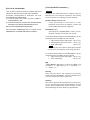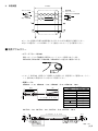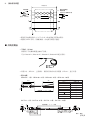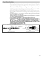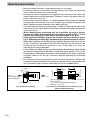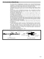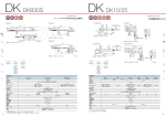
1
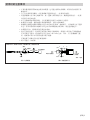
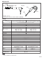
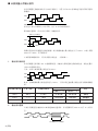
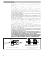
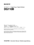
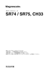
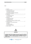
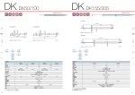
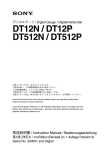
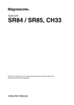
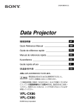
デジタルゲージ /
/ Digital Gauge / Digitale Messtaster
DK812R / DK812R5 /
DK812LR / DK812LR5 /
DK802R / DK802R5 /
DK802LR / DK802LR5
お買い上げいただき、ありがとうございます。
ご使用の前に、この取扱説明書を必ずお読みください。
ご使用に際しては、この取扱説明書どおりお使いください。
お読みになった後は、後日お役に立つこともございますので、必ず保管してください。
Read all the instructions in the manual carefully before use and strictly follow them.
Keep the manual for future references.
Lesen Sie die ganze Anleitung vor dem Betrieb aufmerksam durch und folgen Sie beim Betrieb des
Geräts den Anweisungen. Bewahren Sie diese Bedienungsanleitung zum späteren Nachlesen
griffbereit auf.
取扱説明書 /
Bedienungsanleitung
/ Instruction Manual /
[For U.S.A. and Canada]
[ For EU and EFTA countries ]
THIS CLASS A DIGITAL DEVICE COMPLIES WITH
PART15 OF THE FCC RULES AND THE CANADIAN
ICES-003. OPERATION IS SUBJECT TO THE
FOLLOWING TWO CONDITIONS.
(1) T H I S D E V I C E M A Y N O T C A U S E H A R M F U L
INTERFERENCE, AND
(2) THIS DEVICE MUST ACCEPT ANY INTERFERENCE
RECEIVED, INCLUDING INTERFERENCE THAT
MAY CAUSE UNDERSIGNED OPERATION.
CE Notice
Marking by the symbol CE indicates compliance with the
EMC directive of the European Community. This marking
shows conformity to the following technical standards.
CET APPAREIL NUMERIQUE DE LA CLASSE A EST
CONFORME A LA NORME NMB-003 DU CANADA.
EN 61000-6-2 / 99 :
"Electromagnetic compatibility (EMC) - Part 6-2 : Generic
standards - Immunity for industrial environments"
EN 55011 Group 1 Class A / 98 :
"Limits and methods of measurement of radio
disturbance characteristics of industrial, scientific and
medical (ISM) radio-frequency equipment"
For DC power-driven products to meet EN 61000-6-2 / 99, the
following operational conditions must be satisfied.
1. Input and output signal cable length : 30 m or less
2. Cable length for input power source : 10 m or less
3. Scale cable length :
30 m or less
Note
When using the same cable for output signal and input
power source, the cable must not be longer than 10 m.
For AC power-driven products to meet EN 61000-6-2 / 99, the
following operational conditions must be satisfied.
1. Input and output signal cable length : 30 m or less
2. Scale cable length :
30 m or less
警告
本装置を機械指令 (EN 60204-1) の適合を受ける機器にご使
用の場合は、その規格に適合するように方策を講じてか
ら、ご使用ください。
Warning
When using this device with equipment governed by
Machine Directives EN 60204-1, measures should be taken
to ensure conformance with those directives.
Warnung
Wenn dieses Gerät mit Ausrüstungsteilen verwendet wird,
die von den Maschinenrichtlinien EN 60204-1 geregelt
werden, müssen Maßnahmen ergriffen werden, um eine
Übereinstimmung mit diesen Normen zu gewährleisten.
■ 一般的な注意事項
■ General precautions
以下は当社製品を正しくお使いいただくための一般的注意事
項です。個々の詳細な取扱上の注意は、本取扱説明書に記述
された諸事項および注意をうながしている説明事項に従って
ください。
When using Sony Manufacturing Systems Corporation
products, observe the following general precautions along
with those given specifically in this manual to ensure proper
use of the products.
• 始業または操作時には、当社製品の機能および性能が正常
に作動していることを確認してからご使用ください。
• 当社製品が万一故障した場合、各種の損害を防止するため
の充分な保全対策を施してご使用ください。
• 仕様に示された規格以外での使用または改造を施された製
品については、機能および性能の保証は出来ませんのでご
留意ください。
• 当社製品を他の機器と組合わせてご使用になる場合は、使
用条件、環境などにより、その機能および性能が満足され
ない場合がありますので、充分ご検討の上ご使用くださ
い。
• Before and during operations, be sure to check that our
products function properly.
• Provide adequate safety measures to prevent damages
in case our products should develop malfunctions.
• Use outside indicated specifications or purposes and
modification of our products will void any warranty of the
functions and performance as specified of our products.
• When using our products in combination with other
equipment, the functions and performances as noted in
this manual may not be attained, depending on operating
and environmental conditions.
■ Allgemeine Vorsichtsmaßnahmen
Beachten Sie bei der Verwendung von Sony
Manufacturing Systems Corporation Produkten die
folgenden allgemeinen sowie die in dieser
Bedienungsanleitung besonders hervorgehobenen
Vorsichtsmaßnahmen, um eine sachgerechte Behandlung
der Produkte zu gewährleisten.
• Vergewissern Sie sich vor und während des Betriebs,
dass unsere Produkte einwandfrei funktionieren.
• Sorgen Sie für geeignete Sicherheitsmaßnahmen, um im
Falle von Gerätestörungen Schäden auszuschließen.
• Wenn das Produkt modifiziert oder nicht seinem Zweck
entsprechend verwendet wird, erlischt die Garantie für die
angegebenen Funktionen und Leistungsmerkmale.
• Bei Verwendung unserer Produkte zusammen mit
Geräten anderer Hersteller werden je nach den
Umgebungsbedingungen die in der Bedienungsanleitung
beschriebenen Funktionen und Leistungsmerkmale
möglicherweise nicht erreicht.
DK812R / DK812R5 / DK812LR / DK812LR5 / DK802R / DK802R5 / DK802LR / DK802LR5
安全のために
当社の製品は安全に十分配慮して設計されています。しかし、操作や設置時にまちがった取
扱いをすると、火災や感電などにより死亡や大ケガなど人身事故につながることがあり、危
険です。また、機械の性能を落としてしまうこともあります。
これらの事故を未然に防ぐために、安全のための注意事項は必ず守ってください。操作や設
置、保守、点検、修理などを行う前に、この「安全のために」を必ずお読みください。
警告表示の意味
このマニュアルでは、次のような表示をしています。表示内容をよく理解してから本文をお
読みください。
警告
この表示の注意事項を守らないと、火災や感電などにより死亡や大ケガなど人身事故につな
がることがあります。
注意
この表示の注意事項を守らないと、感電やその他事故によりケガをしたり周辺の物品に損害
を与えることがあります。
注意を促す記号
注意
感電注意
行為を禁止する記号
分解禁止
警告
・ ケーブルを傷つけたり、加工したり、無理に曲げたり、引張ったりしないでくださ
い。また、重いものをのせたり、熱したりしないでください。ケーブルが破損し、火
災や感電の原因となる恐れがあります。
・ 本装置を分解、改造することはおやめください。ケガや感電の恐れがあります。ま
た、内部回路を破損させる原因にもなります。
注意
・ 本装置は防爆構造になっておりませんので、可燃性ガスの雰囲気中でのご使用はおや
めください。火災の原因となることがあります。
(J) i
ii (J)
使用上のご注意
• 本装置に過度の衝撃が加わる場所でのご使用はおやめください。内部を破損、または正
常な出力信号が得られないことがあります。
• コネクタの抜き差しは、破損や誤動作を防ぐため、必ず電源を切ってから行なってくだ
さい。
• 接続コネクタは表示ユニットのコネクタにロックされるまで差し込みます。コネクタ着
脱の際は必ず表示ユニットの電源をOFFにしてから行なってください。
• 特に強力な磁気が発生するものは、測長ユニットから10 cm以上離してください。
• ケーブルを強く引張ったり、ケーブルをつかんで取付けや取外しをしますと、断線の恐
れがあります。
• 測長ユニット本体は、ケーブルのシールド線により、表示ユニットのフレームGND
(アース端子) と電気的に短絡されています。工作機械等へ取付けて他の信号処理装置と
組み合せる場合は、アースレベルにご注意ください。
• 防水型ではありませんので、直接水や油がかからないように使用してください。
• エアーリフター取付口を通じて、真空ポンプなどの利用で測定子操作をする場合には、
図1のような構成の空圧回路を用いますと、エアー駆動が可能となります。真空圧は40∼
66.7 kPa程度が適当です。また、吸排気速度をコントロールするため、専用チューブの
先には図2のようなオリフィスを設けてください。
測定子は排気により引込み操作となります。
• キャリブレーションは1年毎に行なってください。
DK812LR / DK812LR5 / DK802LR / DK802LR5
3
3
バルブ
真空発生源
EXH
VAC
フィッティング
チューブへ
φ2.5
AUS
φ3
VG フィルタ
オリフィス
3
φ0.3
フィッティング
C0.5
VAC.側
取付部
1
単位 : mm
ケーブル
図1.空圧回路
図2.オリフィスの寸法
(J) 1
取付上のご注意
• 測長ユニットの取付けは、必ずステムをチャックしてください。
• 測長ユニットを他の機器に取付ける場合は、本機に直接ねじが当たる固定は絶対に避け
てください。
• 測定子をねじ込む際、スピンドルに過大なトルクをかけますと、内部の機構を損傷する
場合がありますので、絶対に工具を用いず、手で行なってください。
平面測定子を使用される場合以外は、測定子ゆるみ防止のため、付随の呼び2.5のスプリ
ングワッシャをはさむか、ねじロックのご使用をおすすめします。 (締付けトルク参考
値 : 0.05∼0.06 N・m)
• 本品はボール軸受を採用していますので、取付の際にステムを強く締めすぎますと測定
軸を傷つけ、動きを損なう恐れがありますからご注意ください。
• 機械装置へホルダーを使用して取付ける場合には、図4の寸法および材質のホルダーをご
用意いただき、規定トルク0.6 N・mで締付け、固定してください。
• 図4の1 mmスリワリ部に付属の取付スペーサを挿入した場合には、規定トルク0.8 N・m
で締付け、固定が可能です。
• エアー駆動する際に、測定ユニットに取付けるフィッティングは図3の形状のものを準備
してください。特にM4ねじ部の長さ (測長ユニットにねじ込まれる部分の長さ) は4.5 mm
以下としてください。長過ぎる場合、測長ユニットを破損することがあります。
• ケーブルは断線を防ぐため、適当な場所へ固定するようにしてください。また、ケーブ
ルを強く引いたり、無理に曲げてのご使用は避けてください。 (曲げ半径40 mm (内側)
以上)
• スピンドルを機械装置に固定して使用する場合には、カップリングDZ-191 (別売) をご使
用ください。DZ-191の取付方法については、DZ-191の取扱説明書をご参照ください。
• 取付ホルダーを製作するとき、取付平行度は測定精度に影響します。測定面に対する直
角度あるいは走りに対する平行度は、0.02 mm/14 mm以内に調整してください。
M3
O リング
M4
14
18 (*)
オリフィス側
チューブへ
単位 : mm
4.5以下
図3.フィッティング寸法
2 (J)
+0.014
φ8G6 +0.005
DK812LR/DK812LR5/
DK802LR/DK802LR5へ
ねじ込み
φ9
φ3
8.5
1
締付トルク : 0.6 N・m
材質 : SUS303
*DK802R / DK802R5 / DK802LR / DK802LR5の場合、8mm
図4.取付ホルダーの寸法および寸法公差
■ 各部の名称
防塵ベローズ
測定子 (市販の測定子と交換可能)
ステム (φ8 mm)
ケーブル (5m)
エアーリフター取付口
インターポレーションBOX
DK812R
コネクタ
* イラストモデル : DK812LR
* DK812R / DK812R5 / DK802R / DK802R5には、エアーリフターは取付できません。
■ 仕様
高分解能タイプ
DK812R, DK812LR, DK802R, DK802LR
出力
A/B/Z相 電圧差動型ラインドライバ出力 (EIA-422に準拠)
信号ピッチ
最小分解能
40 µm
0.1 µm
0.5 µm
測定範囲
精度 (20 °Cにて)
測定力 (20 °Cにて)
原点
最大応答速度
エアー駆動
汎用分解能タイプ
DK812R5, DK812LR5, DK802R5, DK802LR5
2 mm / 12 mm
1 µmp-p
1.5 µmp-p
2 mmストロークタイプ
下方位 : 0.45 ±0.25 N
横方位 : 0.40 ±0.25 N
上方位 : 0.35 ±0.25 N
12 mmストロークタイプ
下方位 : 0.6 ±0.3 N
横方位 : 0.5 ±0.3 N
上方位 : 0.4 ±0.3 N
一カ所 (スピンドル移動 1 mmの位置にて)
42 m/min
100 m/min
真空引き込み (DK812LR / DK812LR5 / DK802LR / DK802LR5)
耐振動 (10 ∼ 2000 Hz)
100 m/s2
耐衝撃 (11 ms)
1000 m/s2
保護等級
IP66 (インターポレーションBOXとコネクタ除く)
使用温度範囲
0 °C ∼ 50 °C (インターポレーションBOX : 0 °C ∼ 40 °C)
保存温度範囲
−20 °C ∼ 60 °C
電源電圧
DC +5 V ±5%
消費電力
1.8 W
ケーブル長
2.5 m
ステム径
φ8
0
−0.009
質量*1
2 mmストロークタイプ
DK812R / DK812LR : 約30 g
DK802R / DK802LR : 約20 g
12 mmストロークタイプ
DK812R5 / DK812LR5 : 約30 g
DK802R5 / DK802LR5 : 約20 g
測定子
超硬合金球面付 (DZ-123)
取付ねじM2.5
スチール球面付
取付ねじM2.5
付属品
出力ケーブル長 (後続電子部まで)
取付スペーサ
12 m max.
ご注意
*1 質量は、ケーブル部およびインターポレーションBOXを除いたときの値です。
(J) 3
■ 測長ユニット出力信号
本測長ユニットが出力する信号はA/B/Z相信号でEIA-422に準拠した電圧差動型ラインドラ
イバ出力です。
A相
B相
Z相
原点は、A相とB相がHiレベルのときに、Hiレベルになる同期原点です。
最大応答速度時 (約42 m/min時) の出力信号
400 ns (2.5 MHz)
A相
B相
100 ns
本測長ユニットを接続する制御機、またはカウンタの入力最小位相差が100 ns (A相一周期
400 ns 2.5 MHz) より小さいことをお確かめの上ご使用ください。
※特殊仕様にて最小位相差を変更することが可能です。 (1. 出力信号位相差参照)
1. 出力信号位相差
本測長ユニットの移動量は100 ns毎に検出され、移動量に比例した位相差で出力されます。
位相差量は、100 nsの整数倍で変化します。
また、A相とB相の最小位相差は100 nsです。
A相
B相
100 nsの整数倍
標準仕様の最小位相差は100 nsで固定ですが、下記の表の最小位相差については、特殊仕
様として対応します。
A/B相最小位相差
A相一周期
カウンタの許容周波数
最大応答速度
分解能0.1 µm
分解能0.5 µm
備考
100 ns
400 ns
2.5 MHz
42 m/min
100 m/min
標準品
250 ns
1 µs
1 MHz
16.8 m/min
40 m/min
特殊仕様
500 ns
2 µs
500 kHz
8.4 m/min
20 m/min
特殊仕様
2. 出力信号アラーム
本測長ユニットが出力するA/B相は、応答速度を超えた場合アラームとして約400 msの
間、Hiレベル状態となります。
アラーム区間
A/B相はHiレベル状態
4 (J)
3. 受信装置
10 m以下
受信装置
ラインレシーバ
AM26C32または相当品
ラインドライバ
出力 : A/B/Z相
*ケーブルを延長する場合は電源電圧を+5 Vから+5.25 Vの範囲でご使用ください。
*先バラの延長ケーブルはCE22シリーズ (別売アクセサリー) をご使用ください。
■ 別売アクセサリー
• エアーリフター : DZ-801
測定スピンドルの手動操作に便利なエアーリフターが用意されています。
DK812LR / DK812LR5 / DK802LR / DK802LR5との組合せで使用できます。
• スタンド (DZ-501) に取付けてご使用になる場合には、取付用として専用のセットブッ
シュ (DZ-811) が用意されていますのでご利用ください。
• 延長ケーブル
CE22-01 : 1 m、CE22-03 : 3 m、CE22-05 : 5 m、CE22-10 : 10 m
先バラ線 配線色
信号
ケーブル色相
+Vcc
赤
0V
白
A
青
A
黄
B
橙
灰
B
Z
緑
Z
紫
50
13.6
55.5
41.5
ケーブル長 1、3、5、10 m
φ11.8
CK-T12 : 1 m、CK-T13 : 3 m、CK-T14 : 5 m、CK-T15 : 10 m
ケーブル長 1、3、5、10 m
13.6
13.6
φ10
13
13
4.8
6.2
24.3
35.5
49.5
5.5
14
30.5
41.5
5.5
単位 : mm
(J) 5
■ 外形寸法図
単位 : mm
DK812R / DK812R5
ケーブル長 5 m
(101)
ケーブル長 0.3 m
29.7
φ5.7
φ8
(27)
105
18
厚さ : t=21 mm
材質 : PC
DK812LR / DK812LR5
DK802LR / DK802LR5
105
64.2
18
46.2
φ9
φ9
97
21
φ8
21
φ10
φ8
29.7
φ10
12.2 8.6
87
56.2
DK802R / DK802R5
φ8
12.2 8.6
64.2
製品は一部改良のため、予告なく外観・仕様を変更することがあります。
6 (J)
DK812R / DK812R5 / DK812LR / DK812LR5 / DK802R / DK802R5 / DK802LR / DK802LR5
安全预防措施
Sony Manufacturing Systems Corporation 产品是经周密的安全性考虑而设计的。然而,在
运行或安装时不恰当的操作仍是危险的,它可能会引起火灾、触电而导致死亡、重伤等人身事
故。另外,这些操作也可能损坏机器的性能。
因此,为了防止上述意外发生,请务必遵守安全注意事项,在对本装置进行操作、安装、维
修、检查、修理等工作之前,请仔细阅读本“安全预防措施”。
警告标志的意义
本手册中使用下面的标志,在阅读正文之前请先理解它们的含义。
警告
如果不遵守该标志处的注意事项,可能会引起火灾、触电而导致死亡、重伤等人身事故。
注意
如果不遵守该标志处的注意事项,可能会引起触电或其它事故而导致受伤、损坏周围事物等各
种意外。
提醒注意的标志
小心
小心触电
禁止行为的标志
禁止拆卸
警告
・ 不要损坏、加工、过度弯曲、拉、放置重物、或加热电源线,因为这可能损坏电源线而
导致火灾或电击。
・ 不要拆卸、改造本装置,因为这可能会导致受伤或电击。另外,这些行为也可能损坏内
部线路。
注意
・ 本装置没有防爆结构。因此,不要在充有可燃性气体的空气中使用,否则可能导致火灾。
(CS) i
ii (CS)
使用时的注意事项
• 不要在遭受强烈震动的地方使用本装置。这可能会损坏内部线路、或导致无法获得正常
输出信号。
• 为了防止损坏或误操作,在连接或断开连接器之前,一定要关闭电源。
• 将连接器插入显示单元的插口时,要一直插入到其锁定为止。插拔连接器之前,一定要
关闭显示单元的电源。
• 在产生强磁场的场所使用时,令长度测量元件离开 10 厘米以上距离。
• 如果用力拉电缆、握持电缆安装或拆卸的话,可能会造成断线。
• 探测器主体通过电缆的屏蔽线与显示单元的外壳 GND(地线端子)之间电路上处于连接
状态。将其安装到作业机械等与其它信号处理装置组合使用时,请注意接地电平。
• 本装置不防水,使用时请勿直接沾水或油。
• 经由气动机安装口,利用真空泵等进行测定元件操作时,使用图 1 所示的气压线路构成
可以实现空气驱动。适宜的真空压力为 40~66.7 kPa 左右。另外,为了控制抽排气速
度,请按图 2 所示在专用管先端安装节流器。
可通过排气对测定元件进行缩进操作。
• 请 1 年进行一次校准。
DK812LR / DK812LR5 / DK802LR / DK802LR5
接头
3
电缆
图 1.气压线路
3
至接头连接管
φ2.5
阀门
EXH
VAC
φ3
真空制造源
AUS
节流器
3
φ0.3
VG 过滤器
C0.5
VAC.侧
安装部
1
单位:毫米
图 2.节流器的尺寸
(CS) 1
安装时的注意事项
• 安装长度测量元件时,请务必夹住中空管。
• 将长度测量元件安装在其它器械上时,固定时请绝对不要让螺丝接触到本机。
• 旋转安装测定元件时,如果对主轴施加过大的转矩,可能会损坏内部构造,因此切勿使用
工具,请用手进行安装。
除了使用平面测定元件时以外,为防止测定元件松脱,建议您在之间夹入附属的公称口径
2.5 的垫圈,或使用螺丝锁。(锁紧转矩参考值:0.05~0.06 N⋅m)
• 请注意,由于本装置采用球形轴承,安装时如果过度地拧紧中空管,有可能会损伤测量
轴,防碍本装置正常动作。
• 使用固定器将本装置安装到机械装置上时,请准备图 4 所示尺寸及材料的固定器,以规定
转矩0.6 N⋅m将其锁紧并固定。
• 在图 4 所示的 1 毫米裂缝处插入附属的安装销时,可以以规定转矩0.8 N⋅m将其锁紧并固
定。
• 气压驱动时,对于安装在测量元件上的接头,请准备图 3 形状的接头。特别是 M4 螺丝部
的长度(旋入长度测量元件部分的长度)需为 4.5 毫米以下。如果过长,长度测量元件可
能会破损。
• 为防止电缆断线,请将电缆固定在适宜的场所。另外,不要用力拉和过度弯曲电缆。[弯
曲半径 40 毫米(内侧)以上]
• 将主轴固定在机械装置上使用时,请使用耦合器 DZ-191(另购)。有关 DZ-191 的安装
方法,请参照 DZ-191 的使用说明书。
• 制作安装固定器时,安装平行度会影响测量精度。请在 0.02毫米/14 毫米的范围内调整相
对于测量面的直角度或相对于移动方向的平行度。
M3
O型环
14
18(*)
4.5以下
图 3. 接头尺寸
2 (CS)
φ9
φ3
至节流器侧管道
旋入DK812LR/DK812LR5/
DK802LR/DK802LR5
+0.014
φ8G6 +0.005
1
8.5
M4
单位:毫米
锁紧转矩:0.6 N⋅m
材料:SUS303
∗ DK802R / DK802R5 / DK802LR / DK802LR5 时为8毫米
图 4. 安装固定器的尺寸及尺寸公差
■ 各部分名称
防尘波纹管
电缆(5米)
测定元件(可以使用市场销售的测量元件予以更换)
中空管(φ8 毫米)
气动机安装口
内插盒
DK812R
连接器
∗ 图示型号:DK812LR
∗ 无法在 DK812R / DK812R5 / DK802R / DK802R5 上安装气动机。
■ 规格
高分辨率类型
DK812R, DK812LR, DK802R, DK802LR
A/B/Z 相电压差动型线驱动器输出(符合 EIA-422 规定)
输出
信号间距
40 µm
0.1 µm
最小分辨率
0.5 µm
测量范围
2 毫米 / 12 毫米
1 µmp-p
1.5 µmp-p
2 毫米行程类型
下方位:0.45 ± 0.25 N
横方位:0.40 ± 0.25 N
上方位:0.35 ± 0.25 N
12 毫米行程类型
下方位:0.6 ± 0.3 N
横方位:0.5 ± 0.3 N
上方位:0.4 ± 0.3 N
精度(20°C时)
测量力(20°C时)
通用分辨率类型
DK812R5, DK812LR5, DK802R5, DK802LR5
原点
一处(主轴移动 1 毫米处)
最大响应速度
42 米/分钟
气压驱动
真空缩进(DK812LR/DK812LR5/DK802LR/DK802LR5)
100 米/分钟
耐震动(10 ~ 2000 Hz)
100 m/s2
耐冲击(11 ms)
1000 m/s2
保护等级
IP66(内插盒与连接器除外)
使用温度范围
0°C ~ 50°C(内插盒:0°C ~ 40°C)
存放温度范围
–20°C ~ 60°C
电源电压
直流 +5 V ±5%
功耗
1.8 W
电缆长度
2.5 米
中空管口径
质量*1
测量元件
φ8
0
–0.009
2 毫米行程类型
DK812R/DK812LR:约 30 克
DK802R/DK802LR:约 20 克
12 毫米行程类型
DK812R5/DK812LR5:约 30 克
DK802R5/DK802LR5:约 20 克
带超硬合金球面(DZ-123)
安装螺丝 M2.5
带钢球面
安装螺丝 M2.5
附属品
输出电缆长度
(包括后接电子部分)
安装销
最大 12 米
注意
∗1 该数值不包括电缆部分及内插盒的质量。
(CS) 3
■ 长度测量元件输出信号
该长度测量元件输出的信号为 A/B/Z 相信号,为符合 EIA-422 标准的电压差动型线型驱动
器输出。
A相
B相
Z相
原点是 A 相与 B 相均为 Hi 水平时,位于 Hi 水平的同期原点。
最大响应速度时(约 42 米/分钟时)的输出信号
400 ns (2.5 MHz)
A相
B相
100 ns
请确认连接该长度测量元件的控制器,或计数器的输入最小相位差小于 100 ns(A相一周期
400 ns 2.5 MHz)后开始使用。
※如有特殊规格要求,可以改变最小相位差。(请参阅 1)
1.
输出信号相位差
本长度测量元件每隔 100 ns检测移动量,并输出与移动量成比例的相位差。相位差量以
100 ns 的整数倍变化。
另外,A 相与 B 相的最小相位差为100 ns。
A相
B相
100 ns 的整数倍
此外,标准规格的最小相位差固定为 100 ns,下表中所记述的最小相位差作为特殊规格提
供。
A/B 相最小相位差
2.
A 相一周期
计数器容许频率
最大响应速度
分辨率 0.1 μm
分辨率 0.5 μm
备注
100 ns
400 ns
2.5 MHz
42 米/分钟
100 米/分钟
标准品
250 ns
1 μs
1 MHz
16.8 米/分钟
40 米/分钟
特殊规格
500 ns
2 μs
500 KHz
8.4 米/分钟
20 米/分钟
特殊规格
输出信号警报
当该长度测量元件输出的 A/B 相超出响应速度时,作为警报约有 400 ms 处于 Hi 水平状
态。
警报区间
A/B 相处于 Hi 水平状态
4 (CS)
3.
接收信号装置
10 米以下
接收信号装置
线接收器
AM26C32 或等同产品
线驱动器
输出: A/B/Z 相
∗ 使用延长电缆时请在 +5 V 至 +5.25 V 的电源电压范围内使用。
∗ 请使用 CE22 系列(另购附属品)的先端分线延长电缆。
■ 另购附属品
• 气动机:DZ-801
备有便于手动操作测量主轴的气动机。
可与 DK812LR / DK812LR5 / DK802LR / DK802LR5 配合使用。
• 安装在台(DZ-501)上使用时,请使用另备的专用安装器(DZ-811)进行安装。
• 延长电缆
CE22-01 : 1 米、CE22-03 : 3 米、CE22-05 : 5 米、CE22-10 : 10 米
先端分线 配线颜色
信号
电缆色相
+Vcc
红
0V
白
A
蓝
黄
A
橙
B
灰
B
绿
Z
紫
Z
50
13.6
55.5
41.5
电缆长度 1,3,5,10米
φ11.8
CK-T12 : 1 米、CK-T13 : 3 米、CK-T14 : 5 米、CK-T15 : 10 米
电缆长度 1,3,5,10米
13.6
13.6
φ10
13
13
4.8
6.2
24.3
35.5
49.5
5.5
14
30.5
41.5
5.5
单位: 毫米
(CS) 5
■ 外形尺寸图
单位: 毫米
DK812R / DK812R5
电缆长度 5米
电缆长度 0.3米
(101)
29.7
φ5.7
φ8
(27)
105
18
厚度:t=21 毫米
材料:PC(氯丁橡胶)
DK812LR / DK812LR5
DK802LR / DK802LR5
105
64.2
87
29.7
21
φ10
φ8
21
φ8
φ10
12.2 8.6
46.2
18
φ9
97
φ9
56.2
DK802R / DK802R5
φ8
12.2 8.6
64.2
如果对本产品的一部分进行改良,其外观和规格将发生变化,恕不另行通知。
6 (CS)
Safety Precautions
Sony Manufacturing Systems Corporation products are designed in full consideration of
safety. However, improper handling during operation or installation is dangerous and may
lead to fire, electric shock or other accidents resulting in serious injury or death. In addition,
these actions may also worsen machine performance.
Therefore, be sure to observe the following safety precautions in order to prevent these types
of accidents, and to read these "Safety Precautions" before operating, installing, maintaining,
inspecting, repairing or otherwise working on this unit.
Warning Indication Meanings
The following indications are used throughout this manual, and their contents should be
understood before reading the text.
Warning
Failure to observe these precautions may lead to fire, electric shock or other accidents
resulting in serious injury or death.
Caution
Failure to observe these precautions may lead to electric shock or other accidents resulting in
injury or damage to surrounding objects.
Symbols requiring attention
CAUTION
ELECTRICAL
SHOCK
Symbols prohibiting actions
DO NOT
DISASSEMBLE
Warning
• Do not damage, modify, excessively bend, pull on, place heavy objects on or heat the
cable, as this may damage the cable and result in fire or electric shock.
• Do not disassemble or modify the unit, as this may result in injury or electric shock.
These actions may also damage the internal circuitry.
Caution
• The unit does not have an explosion-proof structure. Therefore, do not use the unit in
an atmosphere charged with inflammable gases as this may result in fire.
(E) i
ii (E)
Operating Cautions
• Do not use the unit in places where it may receive excessive shocks. Otherwise
the inside of the unit may be damaged or the unit may become unable to
produce normal output signals.
• Be sure to turn off the power before connecting or disconnecting connectors in oder
to prevent damage or misoperation.
• Insert the connector into the display unit until it locks. Be sure to turn off the
power switch before connecting or disconnecting the connector.
• Locate the measuring unit at least 10 cm/3.94" away from a strong magnetic source.
• Do not forcibly pull the cable for connecting or disconnecting, or it may cause
breakage.
• The measuring unit is short circuited to the frame GND (ground terminal) of the
display unit by shield wire of the cable.
When the measuring unit is used with an other signal processing device on a machine
tool, etc., be aware of the ground level.
• Do not place the probe where it is exposed to splash of water or oil.
• In operating the feeler with a vacuum pump, use such an air-pass system as
shown in Fig. 1 to enable air driving. The optimum vacuum rate is 40 to
66.7 kPa. Further, put such an orifice as shown in Fig. 2 on a tube from the air
lifter connector to control the air suction and discharge speed. The feeler is lifted
at the air discharge to the vacuum pump.
• Recommended calibration interval 1 year.
Vacuum pump
system
VG Filter
OUT
Orifice
Cable
Fig.1 Air-pass System
EXH
VAC
Valve
3/0.12" 3/0.12" 3/0.12"
φ0.3/0.01" dia.
To fitting tube
φ2.5/0.1" dia.
Fitting
φ3/0.12" dia.
DK812LR / DK812LR5 / DK802LR / DK802LR5
C0.5/0.02"
To vacuum
system
1/0.04"
Unit: mm/inch
Fig.2 Dimensions of Orifice
(E) 1
Mounting Instructions
• Be sure to chuck the stem of the measuring unit for mounting.
• If the measuring unit is mounted on another device, ensure that the measuring
unit is free from contact with mount screws.
• If excessive torque is applied on the spindle when screwing in the feeler, the
internal mechanisms can be damaged. Therefore, screw in the feeler with your
hands, and never use a tool.
Except when using a flat feeler, it is recommended to either attach the supplied
spring washer (nominal size: 2.5) or use a screw lock to prevent loosening of the
feeler (tightening torque reference value: 0.05–0.06 N·m).
• The measuring unit comprises ball bearings. Therefore, chucking the stem of the
measuring unit too tightly when mounting may damage the spindle and prevent
its smooth motion.
• When mounting the measuring unit on a machine by using a holder,
prepare the holder with dimensions and material shown in Fig. 4, and fix
the probe by fastening a screw with a specified torque of 0.6 N·m.
• If the supplied installation spacers are inserted into the 1 mm/0.04" slot in
Fig. 4, tightening and securing is possible using a specified torque of 0.8 N·m.
• When using air driving, use the fitting to be attached to the measuring unit as shown
in Fig.3. Especially, the length of the M4 screw section to be inserted into the
measuring unit should be 4.5 mm/0.18" or less. If the screw is too long, the
measuring unit may be damaged.
• Fix the cable in a suitable position to prevent possible cable breakage. Never handle
the cable by forcibly pulling or bending it. (Inside bend radius 40 mm/1.57" or more)
• If the spindle is to be fixed to the machine, use coupling DZ-191 which is optionally
available. Refer to the DZ-191 Instruction Manual regarding the mounting
procedure.
• The measuring accuracy depends on the mounting parallelism. Design and
machine the mounting holder to hold the mounting parallelism of the measuring
unit to the measuring surface to within 0.02 mm/14 mm (0.0008"/0.55").
Fig. 3 Dimensions of Fitting
2 (E)
8.5/0.33"
φ9/0.35" dia.
φ3/0.12 " dia.
4.5 mm (0.18") or less
To orifice tube
18/0.71" (*)
+0.014
1/0.04"
M4
Insert into
DK812LR/DK812LR5/
DK802LR/DK802LR5
14/0.55"
φ8G6 +0.005
+0.0006
/0.31" +0.0002
" dia.
M3
O ring
Unit: mm/inch
Tightening torque: 0.6 N·m
Material: SUS303
* The length for DK802R/DK802R5/DK802LR/
DK802LR5 is 8 mm (0.31")
Fig. 4 Dimensions and Dimensional Tolerance for the
Mounting Holder (Example)
x Names of parts
Anti-dust bellows
Cable (5m/16')
Feeler (interchargeable)
Stem (diameter: 8 mm/0.31")
Air lifter connector
Interpolation box
DK812R
Connector
• Illustration: DK812LR
• The air lifter cannot be attached to the DK812R/
DK812R5/DK802R/DK802R5.
x Specifications
General-purpose resolution models
DK812R5, DK812LR5, DK802R5,
DK802LR5
High-resolution models
DK812R, DK812LR, DK802R, DK802LR
Output
A/B/Z phase voltage-differential line driver output (compliant with EIA-422)
Signal pitch
Resolution
40 µm
0.1 µm
Measuring range
Accuracy (at 20°C/68°F)
Measuring force (at 20°C/68°F)
Reference point
Maximum response speed
Air driving
0.5 µm
2 mm (0.08")/12 mm (0.47")
1 µmp-p
1.5 µmp-p
2 mm/0.08" stroke type
Downward: 0.45 ± 0.25 N
Horizontal: 0.40 ± 0.25 N
Upward: 0.35 ± 0.25 N
12 mm/0.47" stroke type
Downward: 0.6 ± 0.3 N
Horizontal: 0.5 ± 0.3 N
Upward: 0.4 ± 0.3 N
One location (at 1 mm/0.04" position of spindle movement)
42 m/min
100 m/min
Vacuum suction (DK812LR/DK812LR5/DK802LR/DK802LR5)
Vibration resistance
(10 to 2000 Hz)
100 m/s2
Impact resistance (11 ms)
1000 m/s2
Protective structure
Operating temperature
IP66 (not including interpolation box and connectors)
0°C to 50°C/32°F to 122°F (interpolation box: 0°C to 40°C/32°F to 104°F)
Storage temperature
–20°C to 60°C/–4°F to 140°F
Power supply voltage
DC +5 V ±5%
Power consumption
1.8 W
Cable length
Diameter of stem
2.5 m/8.2'
φ8
0
–0.009
0
/ 0.31" –0.0004
Mass *1
2 mm/0.08" stroke type
DK812R/DK812LR: Approx. 30 g/1.06 oz
DK802R/DK802LR: Approx. 20 g/0.7 oz
12 mm/0.47" stroke type
DK812R5/DK812LR5: Approx. 30 g/1.06 oz
DK802R5/DK802LR5: Approx. 20 g/0.7 oz
Feeler
Provided with a carbide ball tip (DZ-123)
Mount screw M2.5
Provided with a steel ball tip
Mount screw M2.5
Accessories
Output cable length
(up to the electronic section)
Installation spacer
12 m/39.4' max.
Note
* The mass indicated is the total mass excluding the cable and interpolation box.
1
(E) 3
x Measuring unit output signals
The signals output from this measuring unit are phase A/B/Z signals in the form of
voltage-differential line driver output compliant with EIA-422.
Phase A
Phase B
Phase Z
The reference point is the synchronized reference point that is at Hi level when the
phase A and phase B are at the Hi level.
Output signals at maximum response speed (at approx. 42 m/min)
400 ns (2.5 MHz)
Phase A
Phase B
100 ns
Before using, check that the minimum input phase difference of the control device
connected to this measuring unit or the counter is smaller than 100 ns (phase A
cycle: 400 ns 2.5 MHz).
* The minimum phase difference can be modified under special specifications.
(See 1. Output signal phase difference)
1. Output Signal Phase Difference
The travel amount of the measuring unit is detected every 100 ns, and the phase
difference proportional to the amount traveled is output. The phase difference
changes in integer multiples of 100 ns.
Also, the minimum phase difference for the phase A and phase B is 100 ns.
Phase A
Phase B
Integer multiple of 100 ns
The minimum phase difference is fixed at 100 ns in the standard specifications,
but the minimum phase differences in the table below are available as special
specifications.
4 (E)
A/B minimum
phase
difference
Phase A cycle
Counter allowable
frequency
100 ns
400 ns
250 ns
500 ns
Maximum response speed
Resolution
0.1 µm
Resolution
0.5 µm
Remarks
2.5 MHz
42 m/min
100 m/min
Standard product
1 µs
1 MHz
16.8 m/min
40 m/min
Special specifications
2 µs
500 kHz
8.4 m/min
20 m/min
Special specifications
2. Output Signal Alarm
If the response speed is exceeded, the phase A/B output from this measuring unit
changes to Hi level for about 400 ms to serve as an alarm.
Alarm section
Phase A/B is Hi level
3. Receiver
10 m/32.8' or less
Line driver
Receiver
Line receiver
AM26C32 or equivalent
Output: phase A/B/Z
∗ If extending the cable, use with a supply voltage in the range from +5 V to
+5.25 V.
∗ Use the CE22 series extension cables for bare wires (optional accessories).
x Optional Accessories
• Air Lifter DZ-801
The air lifter is available for manual operation of the measuring rod.
Use it in combination with DK812LR/DK812LR5/DK802LR/DK802LR5.
• Mounting Bush DZ-811 is optionally available to mount the measuring
unit on Gauge Stand DZ-501.
(E) 5
• Extension cable
CE22-01: 1 m/3.3', CE22-03: 3 m/9.8', CE22-05: 5 m/16', CE22-10: 10 m/32.8'
Bare wire colors
Signal
Color
+Vcc
Red
0V
White
A
Blue
A
Yellow
B
Orange
B
Gray
Green
Z
Z
Violet
50/1.97"
13.6/0.54"
55.5/2.19"
41.5/1.63"
Cable length: 1, 3, 5, 10 m
(3.3', 9.8', 16', 32.8')
4.8/0.19"
6.2/0.24"
Cable length 1, 3, 5, 10 m
(3.3', 9.8', 16', 32.8')
13.6/0.54"
13.6/0.54"
13/0.51"
13/0.51"
φ11.8/0.46" dia.
φ10/0.39" dia.
CK-T12: 1 m/3.3', CK-T13: 3 m/9.8', CK-T14: 5 m/16', CK-T15: 10 m/32.8'
5.5/0.22"
24.3/0.96"
35.5/1.4"
49.5/1.95"
30.5/1.2"
41.5/1.63"
5.5/0.22"
14/0.55"
Uint: mm/inch
x Dimensions
Unit: mm/inch
DK812R / DK812R5
Cable length: 5 m/16'
Cable length: 0.3 m/0.96'
(101/3.98")
φ5.7/0.22" dia.
(27/1.06")
φ8/0.31" dia.
29.7/1.17" 18/0.77"
Thickness: t=21 mm/0.83"
Material: PC
29.7/1.17" 18/0.17"
φ10/0.39" dia.
φ8/0.31" dia.
87/3.43"
DK802LR / DK802LR5
21/0.83"
φ8/0.31" dia.
105/4.13"
φ10/0.39" dia.
DK812LR / DK812LR5
64.2/2.53"
12.2/0.48" 8.6/0.34"
46.2/1.82"
21/0.83"
105/4.13"
φ9/0.35" dia.
97/3.82"
φ9/0.35" dia.
56.2/2.21"
DK802R / DK802R5
φ8/0.31" dia.
12.2/0.48" 8.6/0.34"
64.2/2.53"
Design and specifications are subject to change without notice.
6 (E)
Sicherheitsmaßnahmen
Bei dem Entwurf von Sony Manufacturing Systems Corporation Produkten wird größter Wert
auf die Sicherheit gelegt. Unsachgemäße Handhabung während des Betriebs oder der
Installation ist jedoch gefährlich und kann zu Feuer, elektrischen Schlägen oder anderen
Unfällen führen, die schwere Verletzungen oder Tod zur Folge haben können. Darüber
hinaus kann falsche Behandlung die Leistung der Maschine verschlechtern.
Beachten Sie daher unbedingt die besonders hervorgehobenen Vorsichtshinweise in dieser
Bedienungsanleitung, um derartige Unfälle zu verhüten, und lesen Sie die folgenden
Sicherheitsmaßnahmen vor der Inbetriebnahme, Installation, Wartung, Inspektion oder
Reparatur dieses Gerätes oder der Durchführung anderer Arbeiten durch.
Bedeutung der Warnhinweise
Bei der Durchsicht dieses Handbuchs werden Sie auf die folgenden Hinweise und Symbole
stoßen. Machen Sie sich mit ihrer Bedeutung vertraut, bevor Sie den Text lesen.
Warnung
Eine Missachtung dieser Hinweise kann zu Feuer, elektrischen Schlägen oder anderen
Unfällen führen, die schwere Verletzungen oder Tod zur Folge haben können.
Vorsicht
Eine Missachtung dieser Hinweise kann zu elektrischen Schlägen oder anderen Unfällen
führen, die Verletzungen oder Sachbeschädigung der umliegenden Objekte zur Folge haben
können.
Zu beachtende Symbole
VORSICHT
ELEKTRISCHER
SCHLAG
Symbole, die Handlungen verbieten
NICHT ZERLEGEN
Warnung
• Das Kabel nicht beschädigen, verändern, übermäßig knicken, daran ziehen, schwere
Objekte darauf stellen oder es erwärmen, weil dadurch Beschädigungen, Feuer oder
ein elektrischer Schlag verursacht werden können.
• Unterlassen Sie die Demontage oder die Modifizierung des Gerätes, da dies zu
Verletzungen bzw. zu einem elektrischem Schlag führen kann. Derartige
Maßnahmen können auch den internen Schaltkreis beschädigen.
Vorsicht
• Das Gerät ist nicht explosionsgeschützt. Es darf daher keinesfalls in einer Umgebung
verwendet werden, die brennbare Gase enthält, da hierdurch ein Brand ausgelöst
werden könnte.
(G) i
ii (G)
Zur besonderen Beachtung
• Das Gerät nicht in Umgebungen verwenden, wo es starken Erschütterungen
ausgesetzt ist, da hierdurch das Innere des Geräts beschädigt werden könnte
oder die normale Signalausgabe nicht mehr funktionieren könnte.
• Unbedingt darauf achten, dass die Stromversorgung ausgeschaltet ist, bevor
die Stecker abgezogen werden, damit es nicht zu Schäden oder Fehlfunktionen
kommt.
• Den Stecker an der Anzeigeeinheit einsetzen, bis er festgestellt wird. Bevor
Stecker eingesteckt bzw. abgezogen werden, immer vergewissern das der
Netzschalter ausgeschaltet ist.
• Der Abstand zwischen Messtaster und starken magnetischen Feldern muss
mindestens 10 cm betragen.
• Das Kabel keinesfalls gewaltsam herausziehen oder einstecken, da dies zu
einem Kabelbruch führen kann.
• Der Messtaster ist über die Kabelabschirmung mit der Masse (dem Masseanschluss)
der Anzeigeeinheit verbunden. Wenn Sie den Messtaster mit einem anderen
signalerzeugenden Gerät an einer Werkzeugmaschine oder dergleichen verwenden
wollen, beachten Sie den Massepegel.
• Aufstellorte vermeiden, an denen der Messtaster Wasser oder Ölspritzern
ausgesetzt ist.
• Für den Betrieb des Fühlers mit einer Unterdruckpumpe ist das Druckluftsystem entsprechend Abb.1 anzuordnen. Der optimale Druck liegt bei 40 bis
66,7 kPa. Darüber hinaus ist eine Blende (siehe Abb. 2) am vom
Luftabheberanschluss kommenden Rohr anzubringen, um die Luftansaug- und
Ausstoßgeschwindigkeit zu steuern. Der Fühler wird beim Luftausstoß zur
Unterdruckpumpe gehoben.
• Empfohlener Kalibrierungszyklus 1 Jahr.
DK812LR / DK812LR5 / DK802LR / DK802LR5
3
Anschlussstück
3
3
φ0,3
Unterdruckpumpensystem
EXH
VAC
Blende
Ventil
φ2,5
AUS
φ3
VG Filter
Zum Rohr mit
Anschlußstück
Zum
Unterdrucksystem
C0,5
1
Einheit: mm
Kabel
Abb. 1 Druckluftsystem
Abb. 2 Maße der Blende
(G) 1
Montageanleitung
• Sicherstellen, dass der Schaft des Messtasters für die Montage fest
eingespannt ist.
• Bei der Montage den Messtaster so sichern, dass die Montageschrauben nicht
in direkten Kontakt mit dem Gerät kommen.
• Falls beim Einschrauben des Fühlers ein zu hohes Drehmoment auf die Spindel
ausgeübt wird, kann die interne Struktur beschädigt werden. Schrauben Sie
daher den Fühler nie mit einem Werkzeug, sondern immer von Hand ein.
Bei Verwendung eines flachen Fühlers ist es empfehlenswert eine
Federscheibe mit einer Nenngröße von 2,5 zu verwenden, oder Schraubensicherungskleber aufzutragen.
Um ein Lösen der Verschraubung zu vermeiden, sollte das Anzugsmoment
zwischen 0,05–0,06 N·m liegen.
• Bei der Montage darauf achten, dass der Schaft nicht zu fest eingespannt wird, da
sonst die Kugeln des Kugellagers den Messtaster blockieren und eine einwandfreie
Bewegung verhindern können.
• Zur Montage des Messtasters an einer Maschine mit Hilfe eines Halters für
diesen die in Abb. 4 angegebenen Abmessungen und das angegebene
Material verwenden, und die Schrauben zur Befestigung des Messtasters
mit dem angegebenen Anzugsmoment von 0,6 N·m anziehen.
• Wenn die mitgelieferten Montagezwischenlagen in den in Abb. 4 gezeigten
1-mm-Schlitz eingesetzt werden, ist Anziehen und Sichern mit einem
vorgeschriebenen Drehmoment von 0,8 N·m möglich.
• Benutzen Sie bei Luftantrieb das Anschlussstück, das gemäß Abb. 3 am
Messtaster anzubringen ist. Die Länge des in den Messtaster einzusetzenden
M4-Gewindes darf höchstens 4,5 mm betragen. Ist das Gewinde zu lang, kann
der Messtaster beschädigt werden.
• Das Kabel ist in einer geeigneten Position anzubringen, um einem eventuellen
Kabelbruch vorzubeugen. Niemals das Kabel gewaltsam ziehen oder biegen
(Biegeradius min. 40 mm oder größer).
• Zur Befestigung des Messtasters an einer Maschine verwenden Sie bitte die als
Sonderzubehör erhältliche Kupplung DZ-191. Angaben zum Montageverfahren
sind der Gebrauchsanweisung der Kupplung DZ-191 zu entnehmen.
• Die Messgenauigkeit hängt von der Montageparallelität ab. Der Montagehalter
sollte so ausgelegt und bearbeitet sein, dass die Montageparallelität des
Messtasters zur Oberfläche innerhalb von 0,02 mm/14 mm erhalten bleibt.
M3
O-Ring
18(*)
8,5
φ9
φ3
In DK812LR/DK812LR5/
DK802LR/DK802LR5
einsetzen
Zum Rohr der
Blende
max.4,5 mm
Abb. 3 Maße des Anschlussstücks
+0,014
φ8G6 +0,005
1
M4
2 (G)
14
Einheit: mm
Anzugsmoment: 0,6 N·m
Material: SUS303
* DK802R/DK802R5/DK802LR/DK802LR5 : 8 mm
Abb. 4 Abmessungen und Toleranzen der
Montagehalter (Beispiel)
x Teilebezeichnungen
Staubschutzfaltenbalg
Fühler
(Austauschbar)
Schaft (Durchmesser: 8 mm)
Kabel (5 m)
Luftabheberanschluss
Interpolationseinheit
DK812LR
Stecker
• Abbildung: DK812LR
• Lediglich der Luftabheber ist am DK812R/DK812R5/
DK802R/DK802R5 nicht anzubringen.
x Technische Daten
Modelle mit hoher Auflösung
DK812R, DK812LR, DK802R, DK802LR
Ausgabe
A/B/Z-Phasen-Spannungsdifferential-Leitungstreiberausgabe (entspricht EIA-422)
40 µm
Signalteilung
Auflösung
0,5 µm
0,1 µm
2 mm/12 mm
Messbereich
Genauigkeit (bei 20°C)
Messkraft (bei 20°C)
Bezugspunkt
Maximale Ansprechgeschwindigkeit
Luftantrieb
Allzweckmodelle mit normaler Auflösung
DK812R5, DK812LR5, DK802R5,
DK802LR5
1 µms-s
1,5 µms-s
Typ mit 2 mm Hub
Abwärts: 0,45 ± 0,25 N
Horizontal: 0,40 ± 0,25 N
Aufwärts: 0,35 ± 0,25 N
Typ mit 12 mm Hub
Abwärts: 0,6 ± 0,3 N
Horizontal: 0,5 ± 0,3 N
Aufwärts: 0,4 ± 0,3 N
Eine Position (bei 1-mm-Position der Spindelbewegung)
42 m/min
100 m/min
Unterdrucksaugung (DK812LR/DK812LR5/DK802LR/DK802LR5)
Vibrationsfestigkeit (10 bis 2.000 Hz)
100 m/s2
Schlagfestigkeit (11 ms)
1000 m/s2
Schutzklasse
Betriebstemperatur
Lagertemperatur
IP66 (ohne Interpolationseinheit und Stecker)
0°C bis 50°C (Interpolationseinheit: 0°C bis 40°C)
–20°C bis 60°C
DC +5 V ±5%
Spannungsversorgung
1,8 W
Stromversorgung
2,5 m
Kabellänge
φ8
Schaftdurchmesser
Masse
*1
Fühler
Zubehör
Ausgangskabellänge
(bis zum Elektronikteil)
0
–0,009
Typ mit 2 mm Hub
DK812R/DK812LR: ca. 30 g
DK802R/DK802LR: ca. 20 g
Typ mit 12 mm Hub
DK812R5/DK812LR5: ca. 30 g
DK802R5/DK802LR5: ca. 20 g
mit Hartmetallkugelspitze (DZ-123)
M2,5-Befestigungsschraube
mit Stahlkugelspitze
M2,5-Befestigungsschraube
Montagezwischenlage
max. 12 m
Hinweis
*1 Der Gewichtswert schließt nicht das Kabel oder die Interpolationseinheit ein.
(G) 3
x Messtaster-Ausgangssignale
Bei den von diesem Messtaster ausgegebenen Signalen handelt es sich um A/B/
Z-Phasensignale in Form einer Spannungsdifferential-Leitungstreiberausgabe
gemäß EIA-422.
A-Phase
B-Phase
Z-Phase
Der Bezugspunkt ist der synchronisierte Bezugspunkt, der sich auf H-Niveau
befindet, wenn A-Phase und B-Phase sich auf H-Niveau befinden.
Ausgangssignale bei maximaler Ansprechgeschwindigkeit (bei ca. 42 m/min)
400 ns (2,5 MHz)
A-Phase
B-Phase
100 ns
Vergewissern Sie sich vor Gebrauch, dass die minimale Eingangsphasendifferenz
der mit diesem Messtaster verbundenen Steuervorrichtung kleiner als 100 ns ist
(A-Phasenzyklus: 400 ns 2,5 MHz).
* Die minimale Phasendifferenz kann unter Sonderspezifikationen modifiziert
werden.
(Siehe 1. Ausgangssignal-Phasendifferenz)
1. Ausgangssignal-Phasendifferenz
Der Hubbetrag des Messtasters wird alle 100 ns abgetastet, und die
Phasendifferenz proportional zum Hubbetrag wird ausgegeben. Die
Phasendifferenz ändert sich in ganzzahligen Vielfachen von 100 ns.
Außerdem beträgt die minimale Phasendifferenz für die A-Phase und B-Phase
100 ns.
A-Phase
B-Phase
Ganzzahliges Vielfaches von 100 ns
Die minimale Phasendifferenz ist bei den Standardspezifikationen auf 100 ns
fixiert, aber die in der nachstehenden Tabelle aufgeführten minimalen
Phasendifferenzen sind als Sonderspezifikationen erhältlich.
Minimale A/BPhasendifferenz
A-PhasenZyklus
Zulässige
Zählerfrequenz
100 ns
400 ns
250 ns
500 ns
4 (G)
Maximale
Ansprechgeschwindigkeit
Bemerkungen
Auflösung
0,1 µm
Auflösung
0,5 µm
2,5 MHz
42 m/min
100 m/min
Standardprodukt
1 µs
1 MHz
16,8 m/min
40 m/min
Sonderspezifikationen
2 µs
500 kHz
8,4 m/min
20 m/min
Sonderspezifikationen
2. Ausgangssignalalarm
Falls die Ansprechgeschwindigkeit überschritten wird, wechselt die von diesem
Messtaster ausgegebene A/B-Phase für etwa 400 ms auf H-Niveau, um als Alarm
zu dienen.
Alarmabschnitt
A/B-Phase auf H-Niveau
3. Empfänger
10 m oder weniger
Leitungstreiber
Empfänger
Leitungsempfänger
AM26C32 oder Entsprechung
Ausgabe: A/B/Z-Phase
∗ Bei Verlängerung des Kabels ist eine Versorgungsspannung im Bereich von
+5 V bis +5,25 V zu verwenden.
∗ Verwenden Sie Verlängerungskabel der Serie CE22 für die blanken Drähte
(gesondert erhältliches Zubehör).
x Sonderzubehör
• Luftabheber DZ-801
Der Luftabheber ist für den Handbetrieb des Messstabs lieferbar. Den Heber
zusammen mit DK812LR/DK812LR5/DK802LR/DK802LR5 verwenden.
• Die Montage buchse DZ-811 ist als Option erhältlich, um den Messtaster am
Montagehalter DZ-501 anzubringen.
(G) 5
• Verlängerungskabel
CE22-01: 1 m, CE22-03: 3 m, CE22-05: 5 m, CE22-10: 10 m
55,5
41,5
Blankdrahtfarben
Signal
Farbe
+Vcc
Rot
0V
Weiß
A
Blau
A
Gelb
B
Orange
B
Grau
Grün
Z
Z
Violett
13,6
50
Kabellänge: 1, 3, 5, 10 m
φ11,8
CK-T12: 1 m, CK-T13: 3 m, CK-T14: 5 m, CK-T15: 10 m
Kabellänge: 1, 3, 5, 10 m
13,6
13,6
φ10
13
13
4,8
6,2
5,5
14
24,3
35,5
49,5
5,5
30,5
41,5
Einheit : mm
x Abmessungen
Einheit : mm
DK812R / DK812R5
Kabellänge: 5 m
(101)
Kabellänge: 0,3 m
29,7
φ5,7
φ8
(27)
105
18
Dicke:
t=21 mm
Material: PC
DK812LR / DK812LR5
DK802LR / DK802LR5
105
64,2
18
φ10
φ8
21
φ10
φ8
29,7
46,2
φ9
97
21
12,2 8,6
87
φ9
56,2
DK802R / DK802R5
φ8
12,2 8,6
64,2
Änderungen der technischen Daten und des Aussehens jederzeit vorbehalten.
6 (G)
このマニュアルに記載されている事柄の著作権は当
社にあり、説明内容は機器購入者の使用を目的とし
ています。
したがって、当社の許可なしに無断で複写したり、
説明内容(操作、保守など)と異なる目的で本マ
ニュアルを使用することを禁止します。
The material contained in this manual consists of
information that is the property of Sony
Manufacturing Systems Corporation and is intended
solely for use by the purchasers of the equipment
described in this manual.
Sony Manufacturing Systems Corporation expressly
prohibits the duplication of any portion of this manual
or the use thereof for any purpose other than the
operation or maintenance of the equipment
described in this manual without the express written
permission of Sony Manufacturing Systems
Corporation.
Le matériel contenu dans ce manuel consiste en
informations qui sont la propriété de Sony
Manufacturing Systems Corporation et sont
destinées exclusivement à l'usage des acquéreurs
de l'équipement décrit dans ce manuel.
Sony Manufacturing Systems Corporation interdit
formellement la copie de quelque partie que ce soit
de ce manuel ou son emploi pour tout autre but que
des opérations ou entretiens de l'équipement à moins
d'une permission écrite de Sony Manufacturing
Systems Corporation.
Die in dieser Anleitung enthaltenen Informationen
sind Eigentum von Sony Manufacturing Systems
Corporation und sind ausschließlich für den
Gebrauch durch den Käufer der in dieser Anleitung
beschriebenen Ausrüstung bestimmt.
Sony Manufacturing Systems Corporation untersagt
ausdrücklich die Vervielfältigung jeglicher Teile
dieser Anleitung oder den Gebrauch derselben für
irgendeinen anderen Zweck als die Bedienung oder
Wartung der in dieser Anleitung beschriebenen
Ausrüstung ohne ausdrückliche schriftliche Erlaubnis
von Sony Manufacturing Systems Corporation.
保 証 書
お
客
様
保証規定
お フリガナ
名
前
ご 〒
住
所
様
電話
1 保証の範囲
取扱説明書、本体添付ラベル等の注意書に従った正
- -
常な使用状態で、保証期間内に故障した場合は、無
償修理いたします。
本書に基づく保証は、本商品の修理に限定するもの
保期
証間
型
名
お買上げ日
年
月
日
本 体
1
年 とし、それ以外についての保証はいたしかねます。
2 保証期間内でも、次の場合は有償修理となります。
火災、地震、水害、落雷およびその他天災地変によ
る故障。
DK812R / DK812R5 / DK812LR / DK812LR5 /
DK802R / DK802R5 / DK802LR / DK802LR5
使用上の誤りおよび不当な修理や改造による故障。
消耗品および付属品の交換。
本書の提示が無い場合。
本書にお買い上げ日、お客様名、販売店名等の記入
お買上げ店住所・店名
が無い場合。(ただし、納品書や工事完了報告書が
ある場合には、その限りではありません。)
3 離島、遠隔地への出張修理および持込修理品の出張修理
については、出張に要する実費を別途申し受けます。
電話
- -
印
本書はお買上げ日から保証期間中に故障が発生した場
合には、右記保証規定内容により無償修理を行うこと
をお約束するものです。
4 本書は日本国内においてのみ有効です。
5 本書の再発行はいたしませんので、紛失しないよう大切
に保管してください。
ソニーマニュファクチュアリングシステムズ株式会社
〒346-0035 埼玉県久喜市清久町1-10
Sony Manufacturing Systems Corporation
1-10 Kiyoku-cho, Kuki-shi, Saitama 346-0035 Japan
http://www.sonysms.co.jp/
DK812R / DK812R5 / DK812LR / DK812LR5 / DK802R /
DK802R5 / DK802LR / DK802LR5
2-637-295-01
このマニュアルは再生紙を使用しています。
2005.5
Printed in Japan
©2005 Sony Manufacturing Systems Corporation