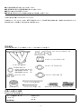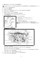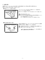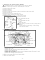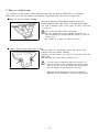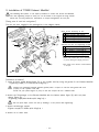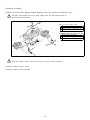
1
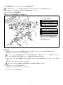
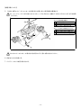
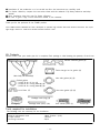
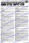
03/2006
M19K301
取扱説明書
Instructions manual
エキゾーストマニホールド RB26DETT
Exhaust Mani
f
ol
d RB26DETT
品
番
Part Number
193084
適 合 : BNR32、BCNR33、BNR34 RB26DETT 搭載車
Application: BNR32,BCNR33,BNR34 Cars equipped with the RB26DETT engine
日本語・・・・・・・・・・・・・・3p
English・・・・・・・・・・・・・
11p
- 1 -
- 2 -
●この取扱説明書を良く読んでからお使いください
●日産自動車の発行する整備要領書と併せてお使いください
●取り付け後も大切に保管してください
●販売店様で取り付けをされる場合は本書を必ずお客様へお渡しください
TOMEI 製品のお買い上げありがとうございます。
TOMEIエキゾーストマニホールドは、排気干渉を抑えたスムーズな排気を促す設計を施し、材質にはSUS304ステンレス
材を使用することで軽量化、耐久性の向上を実現しました。
部品構成
下記の内容・数量が揃っているかを確認してください。( )内は同梱されている数量です。
エキゾ-ストマニホールドガスケット (2)
ターボチャージャーインレットガスケット (2)
マニホールド本体(2)
インレットチューブガスケット(A) (2)
アイボルトガスケット
・オイルライン用φ12.5-18 (4)
・冷却水(A)用φ14.2-20
(4)
・冷却水(B)用φ18.1-24
(2)
ロックプレート(4)
インレットチューブガスケット(B) (2)
バンテージバンド(長)(2)
バンテージ (1)
バンテージバンド(短)(12)
作業に必要な工具類
取り付けには下記が必要です。
・エンジン整備用工具一式
・冷却水(LLC)
・トルクレンチ
・整備要領書
・ハンマー
・あて木
- 3 -
ボルトスムースペースト(1)
ステッカー (2)
注 意
■本品は自動車競技専用部品です。サーキットや公道から閉鎖されたコース内に限って使用してください。
■本品の取り付けは特別の訓練を受けた整備士が、設備の整った作業場で実施してください。
■指定する車種以外への取り付けはおやめください。本品およびエンジンを破損する恐れがあります。
■取り付けの際は、適切な工具、保護具を使用しないと、けがにつながり危険です。
警 告
■本品の取り付けはエンジン及びエンジンルーム内が冷えた状態で行ってください。
■部品欠落による車輌の破損・火災が起こる可能性があるため、製品構成部品の取り付けは確実に行ってください。
- 4 -
1.純正エキゾーストマニホールドの取り外し
ここで記載するのはマニホールドを取り外す為の簡易手順です。各部の詳細な脱着方法は、必ず整備要領書を参照してください。
1. バッテリーマイナス端子を取り外す。
2. アンダーカバーを取り外す。
3. フロントパイプを取り外す。
4. ラジエタードレーンプラグおよびラジエターキャップを外して冷却水(LLC)を抜き取る。
5. ストラットタワーバーを取り外す。
6. エアダクト、エアクリーナーケースを取り外す。
7. O2センサーコネクターおよびハーネスコネクターを取り外す。
※この時復帰時に各カプラー同士の判別がつきやすいようにしておく。
8. エアホースを取り外す。
(1) ブラケットから取り外す
エアホース
リヤターボチャージャー
アウトレットチューブ
エアホース
(2) ・リヤターボチャージャーアウトレットチューブ
・エアホース
・フロントターボチャージャーアウトレットチューブ
・エアチューブ
これらのホース類を取り外す。
・合いマークをそれぞれに印しておくと復帰時が容易です。
・異物が入らないようターボチャージャーの開口部を塞いでください。
フロントターボ
チャージャー
アウトレットチューブ
エアチューブ
9. 配管を取り外す。
ウォーターリターンチューブA
ウォーターコネクター
ウォーターリターンチューブC
エアチューブ
ウォーターリターンチューブB
オイルフィードチューブアイボルト
ウォーターフィードチューブ
アイボルト
オイルフィードチューブアイボルト
オイルリターンホース
ウォーターフィード
チューブアイボルト
ターボチャージャーサポート
ターボチャージャーサポート
(1) ウォーターリターンチューブAを取り外す。
(2) エアチューブを取り外す。
(3) ウォーターリターンチューブB、および、ウォーターリターンチューブCを取り外す。
(4) エキゾーストマニホールドカバーを取り外す。
(5) ウォーターフィードチューブアイボルト、および、オイルフィードチューブアイボルトを取り外す。(各2ヶ所)
(6) オイルリターンホースを取り外す。
(7) ターボチャージャーサポートを取り外す。(2ヶ所)
10. エキゾーストマニホールドからターボチャージャーASSYを取り外す。
11. エキゾーストマニホールドを取り外す。
- 5 -
2.遮熱対策
使用時にエキゾーストマニホールドから発せられる熱を遮熱するため、事前に対策する必要があります。
遮熱の方法を次の2例より選択し、実施してください。
■付属のバンテージを使用する場合
エキゾーストマニホールド(左右)に付属のバンテージを巻き付け、
バンテージバンドを使って固定する。
【参考:バンテージは巻く前に、バンテージを水に濡らし、絞ってから使用します。】
・純正遮熱板は使用しません。
・バンテージバンドは留めた後に長さに余分がある場合は、ニッパー
などで不要な長さをカットしてください。
また、その際の切り口でけがをしないよう注意してください。
■純正遮熱板を使用する場合
左図の矢印箇所がエキゾーストマニホールドに干渉するため、遮熱板
の表側に当て木をし、裏側からハンマーで叩き出す。
・遮熱板を叩き出す事により、遮熱板取付用の穴位置がずれた
場合、穴をヤスリなどで拡大してください。
・エキゾーストマニホールドに付属のバンテージなどを使用する
場合、遮熱板の取り付けはできません。
- 6 -
3.TOMEI
エキゾーストマニホールドの取り付け
ここで記載するのはマニホールドを装着する簡易手順です。各部の主な締め付けトルクは整備要領書に準じます。
トルク指示されていない箇所のトルク管理は必ず整備要領書に従ってください。
【各ボルト・ガスケットの装着位置図】
同梱のガスケット類の使用箇所は下図の通りです。
<キット内付属品使用箇所>
⑩
⑦
①
⑩
⑩
①
⑩
⑤
※
⑤
※
⑤
⑤
②
⑥
⑥
②
⑦
④
⑦
①
②
③
④
⑤
エキゾ-ストマニホールドガスケット
ターボチャージャーインレットガスケット
インレットチューブガスケット(A)
インレットチューブガスケット(B)
ロックプレート
<ノーマル使用箇所と締め付けトルク>
⑥ 17.7∼23.5N・m (1.8∼2.4kgf-m)
⑦ 15.7∼20.6N・m (1.6∼2.1kgf-m)
⑧ 15.7∼20.6N・m (1.6∼2.1kgf-m)
⑨ 15.7∼20.6N・m (1.6∼2.1kgf-m)
⑩ 22.6∼29.4N・m (2.3∼3.0kgf-m)
④
ボルト部分には焼き付きや固着を防止する為、
付属のボルトスムースペーストを塗布してください。
③
⑧
⑨
③
※部分は装着方向に注意
⑧
⑨
【装着手順】
1. TOMEIエキゾーストマニホールドを付属のガスケット(上図①)をシリンダーヘッドとの間に挟み取り付ける。
<締め付けトルク[17.7∼23.5N・m(1.8∼2.4kgf-m)] >
・シリンダーヘッド側に異物(純正ガスケット跡)の付着がないよう、事前にスクレーパーで取り除いてください。
・ヨーク(上図※部)は平らな面がマニホールド側になるよう取り付けてください。
1. エキゾーストマニホールドに付属のガスケット(上図④)、ロックプレート(上図⑤)を用い、ターボチャージャーを取り
付ける。
<締め付けトルク[22.6∼29.4N・m(2.3∼3.0kgf-m)] >
ロックプレートはナットを締め付け後に確実にツメを折り曲げて固定してください。
2. ターボチャージャーサポートを取り付ける。
<締め付けトルク[15.7∼20.6N・m(1.6∼2.1kgf-m)] >
4. オイルリターンホースを取り付ける。
- 7 -
【装着手順(つづき)】
5. その他、純正エキゾーストマニホールドを取り外した際に外した周辺部品を復帰する。
ウォーターチューブアイボルトおよびオイルチューブアイボルトは、付属のアイボルトガスケットをそれぞれ使用
してください。
b
<キット内付属品使用箇所>
②
① 冷却水(A)用φ14.2-20
② 冷却水(B)用φ18.1-24
③ オイルライン用φ12.5-18
②
a
a
①
③
①
c
<各ノーマルボルトの締め付けトルク>
a 29.4∼39.2N・m(3.0∼4.0kgf-m)
b 33.0∼41.0N・m(3.4∼4.2kgf-m)
c 14.7∼19.6N・m(1.5∼2.0kgf-m)
①
③
c
リヤO2センサーコネクターは取り外し時と同じカプラー同士を取り付けてください。
6.冷却水(LLC)を充填する。
7.バッテリーマイナス端子を取り付ける。
- 8 -
4.取り付け後の確認
1.エキゾーストマニホールドに周辺部品、配線の干渉がないか確認する。
2.エンジンを始動し、排気漏れがないか確認する。
装着後、遮熱対策としてマニホールドにバンテージを巻き付けている場合、排気ガスに熱せられると一時的に
煙が発生します。換気の良い場所でエンジンを始動させてください。
警 告
・干渉があると周辺部品が損傷し、車両火災や故障の原因となる為確認は慎重に行ってください。
・排気漏れがあると、性能の低下や、排気ガスによる中毒を起こす原因となり危険です。
- 9 -
Notes
- 10 -
● I
nstallation of the production is to be carried out after the instructions are carefully read.
● For further reference, compare this instruction sheet with the authentic Fuji Heavy Industries workshop
manual.
● After installation, keep this copy for future reference.
● Be sure to give a copy of this instruction manual to the customer.
Thank you for the purchase of this TOMEI product.
The TOMEI Exhaust Manifold has been developed to optimize high exhaust flow with minimal resistance. The super
light weight material is made from durable SUS304 stainless steel.
Kit Contents
Please confirm that your outlet pipe kit is complete. Each package is label showing the quantity of each item
Exhaust manifold gasket (2)
Turbo-charger Inn let gasket (2)
Main body of manifold(2)
Inlet tube gasket (A) (2)
Eyebolt gasket
・φ12.5-18 for oil line (4)
・φ14.2-20 for cooling water(A) (4)
・φ18.1-24 for cooling water(B) (2)
Lock Plate (4)
Inlet tube gasket (B) (2)
Bandage band (long) (2)
Bandage(1)
Bandage band (short) (12)
Bolt smooth paste (1)
Tools required for installation
The following tools are necessary for the installation.
・General maintenance tools
・Torque wrench
・Servicing instruction
・Water Coolant
・Hammer
・Splint
- 11 -
(LLC)
Sticker (2)
Caution
■ This product is only for vehicle use under a closed circuit and for public roads.
■ The technician for this installation must be a licensed mechanic, which holds a thorough understanding for
installations.
■ Only install this product on the specific model as stated above. If installed on a differant model, possible
engien damage will occur.
■ Only use the proper tools during installation.
If wrongful tools are used, possible injury will occur.
Warning
■ Install this item when the engine is cold.
■ The installation of all kit components must always be done with care as there is always a possibility of
engine fire. It is best to Install this part(s) when the engine & engine bay is cold.
- 12 -
1. Removal of the Genuine Exhaust Manifold
The following descriptions are simple procedures to remove the factory Manifold.
Refer to the servicing instruction for a detailed description on each part.
1.
2.
3.
4.
5.
6.
7.
Remove
Remove
Remove
Remove
Remove
Remove
Remove
a battery minus terminal.
an undercover.
the front pipe.
the radiator drain plug and a radiator cap and drain the water coolant (LLC).
strut tower bar.
the air duct and air cleaner/filter case.
O2 sensor connector and a harness connector.
※Please take note of each coupler to not confuse where they belong.
8. Remove the air hose.
Air hose
(1) Remove from bracket.
(2) ・Rear turbocharger outlet tube
Rear turbocharger
outlet tube
Air hose
Front
turbocharger
outlet tube
・Air hose
・Front turbocharger outlet tube
・Air tube
Remove these hose.
When returning, it is possible to do easily by making marks for
reference.
Seal the opening of the turbo-charger so that the foreign
matter enters the housing.
Air tube
9. Remove piping.
Water return tube A
Water connector
Air tube
Water return tube C
Water return tube B
Oil feed tube aibolt
Water feed tube aibolt
Oil feed tube aibolt
Oil return hose
Water feed
tube aibolt
Turbocharger support
Turbocharger support
(1)
(2)
(3)
(4)
(5)
(6)
(7)
Remove
Remove
Remove
Remove
Remove
Remove
Remove
the water return tube A.
the air tube.
the water return tube B and the water return tube C.
Exhaust Manifold cover.
the water feeding tube eyebolt and the oil feeding tube eyebolt. (Two points for each)
the oil return hose.
the turbocharger bracket. (Two points)
10. Remove a turbo-charger ASSY from an exhaust manifold.
11. Remove the exhaust manifold.
- 13 -
2. Ways to reduce heat
It is necessary to plan how to reduce unwanted heat from the exhaust manifold prior to installation.
Please take note from the following two examples, and decide your action plan to reduce heat.
■When you use the Thermo Bandage.
Securing by twisting the Bandage (supplied) around the
Exhaust Manifold (both right & left), and using the Bandage.
[ Ref: Soak the bandage in water & then sqeeze any excess water before
it applying it ]
・Do not use the Genuine heat shield plate.
・Cuts any unnecessary excess bandage with nippers etc.
Has the bandage got enough sufficient length to cover the
surface area.
Be careful not to suffer any injuries from cuts.
■ When a genuine heat shield plate is used.
The arrow part in a left diagram shows the sections that
interferes with the exhaust manifold.
Therefore you will need to cut a splint in the side of the heat
shield plate.
And then beat into shape with a hammer to fit.
・You may need to expand the hole with a file etc. to
position the hole for the installation of the heat shield
plate as the hole may have shifted with the alteration
that was made from the beating on the plate.
・When the Thermo Bandage is used on the Exhaust
Manifold the heat sheild plate cannot be used anymore.
- 14 -
3. Installation of TOMEI Exhaust Manifold
The following descriptions is the simple procedure to remove the attach the Manifold.
The main tightening torque of each part can be found in the original servicing manual.
Follow the servicing manual for information on torque management of each part.
【Fixing point of each bolt and gasket.】
The use the parts supplied in the packaged as in the diagram below.
⑩
①
<Part
①
⑦
②
③
④
⑦
⑤
⑩
⑩
①
⑩
⑤
※
⑤
※
⑤
②
⑥
⑥
②
⑤
④
⑦
of use accessory in kit>
Exhaust Manifold gasket
Turbo-charger inlet gasket
Inlet tube gasket (A)
Inlet tube gasket (B)
Lock plate
<Normal use part and tightening torque>
⑥ 17.7-23.5N・
m (1.8-2.4kgf-m)
⑦ 15.7-20.6N・
m (1.6-2.1kgf-m)
⑧ 15.7-20.6N・
m (1.6-2.1kgf-m)
⑨ 15.7-20.6N・
m (1.6-2.1kgf-m)
⑩ 22.6-29.4N・
m (2.3-3.0kgf-m)
④
Spread a bolt smooth paste of the attachment
to prevent burning and clinging inthepart.
③
⑧
③
⑨
※Be careful of the direction of theinstallation
in the part.
⑧
⑨
【Installation procedure】
1. Insert & attach gasket (Above figure ①) to the cylinder head by using the gasket for the Exhaust Manifold.
<Tightening torque[17.7-23.5N・m(1.8∼2.4kgf-m)] >
・Remove any unwanted material (genuine gasket) with a scraper so that the new gasket will stick
properly to the cylinder head side.
・Install the york (above figure ※ part) so that flat respect will be a manifold side.
2. Attach the Turbocharger to the Exhaust Manifold with the Gasket (above figure ④) and Lock plate
(above Figure ⑤)
<Tightening torque[22.6-29.4N・m(2.3-3.0kgf-m)] >
The lock plate helps secure the nut by bending it to fix (check after tightening).
3. Attach turbocharger support.
<Tighten torque[15.7-20.6N・m(1.6-2.1kgf-m) >
4. Attach an oil return hose.
- 15 -
【Installation procedure】
5. When you remove other genuine Exhaust Manifolds, return the removed circumference parts.
The water tube eyebolt and the oil tube eyebolt must use the eyebolt gasket of
the attachment respectively.
b
<Part of use accessory in kit>
②
①
②
③
②
φ14.2-20 for @ cooling water (A)
φ18.1-24 for A cooling water (B)
φ12.5-18 for B oil line
<Tightening torque of normal each bolt>
a
③
①
a
①
c
a
b
29.4-39.2N・
m(3.0-4.0kgf-m)
33.0-41.0N・
m(3.4-4.2kgf-m)
c
14.7-19.6N・
m(1.5-2.0kgf-m)
①
③
c
Install the coupler similar to the removed one in rear O2 sensor connector.
6. Refill the water coolant
(LLC).
7. Attach a battery minus terminal.
- 16 -
4.The Confirmation after completing the attachment
1. Double check to ensure all work is completed well and that there is no interference with any parts or
wirings with the Exhaust Manifold.
2. Start the engine and confirm that there is no signs of any exhaust leakage.
If the Bandage that is wrapped around the manifold is heated up the vehicle exhaust emission after it
can emit smoke for short periods until it is bedded in.
Start the engine in the place where ventilation is good.
Warning
・Inhaling exhaust over a short period of time will cause injury.
ventilated.
Please make sure your working area is well
・Make sure no obtrusive objects are in the way during engine running.
Confirm whether to interfere with neither parts nor peripheral wirings in Exhaust Manifold..
- 17 -
Notes
- 18 -
1737-3 Tsuruma Machida-shi Tokyo 194-0004,JAPAN
Telephone +81-42-795-8411(main switchboard) /Facsimile +81-42-799-7851
URL:http://www.tomei-p.co.jp
● If you have any questions in regards to the installation of this product, please contact your local distributor
or Tomei Powered in the above contact details.
OPEN: Monday - Friday (National holidays and public holidays excluded). 09:00AM - 18:00PM
- 19 -
〒194-0004 東京都町田市鶴間1737−3
TEL
042−795−8411(代)
FAX 042−799−7851
http://www.tomei-p.co.jp
●この製品に関わる取り付け、操作上のご相談は上記へお願いします。営業時間:月∼金(祝祭日、年末年始を除く)9:00∼18:00
エキゾーストマニホールド RB26 取扱説明書
- 20 -
06年3月 M19K301