1
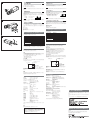
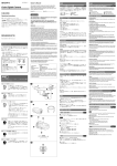
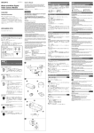
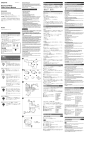
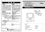
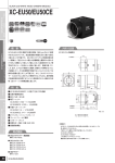
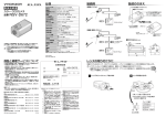
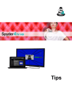
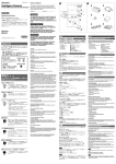
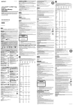
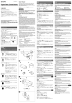
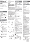
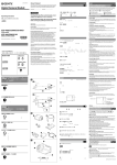
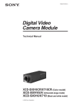
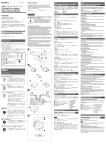
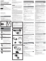
3-854-202-02 (1) Black-and-White Digital Video Camera Module Owner’s Record The model and serial numbers are located on the bottom. Record the serial number in the space provided below. Refer to these numbers whenever you call upon your Sony dealer regarding this product. Model No. XCD-SX910UV Serial No. ______________ お買い上げいただきありがとうございます。 電気製品は、安全のための注意事項を守らないと、けがをし たり周辺の物品に損害を与えることがあります。 この取扱説明書には、事故を防ぐための重要な注意事項と製品の取り扱い かたを示してあります。この取扱説明書をよくお読みのうえ、製品を安全 にお使いください。お読みになったあとは、いつでも見られるところに必 ず保管してください。 XCD-SX910UV 2004 Sony Corporation Printed in Japan 安全のために ソニー製品は安全に充分に配慮して設計されています。しかし、まちがった 使いかたをすると、火災や感電などにより死亡や大けがなど人身事故につな がることがあり、危険です。 事故を防ぐために次のことを必ずお守りください。 • 安全のための注意事項を守る。 • 長期間、安全にお使いいただくために、定期点検をすることをおすすめ します。点検の内容や費用については、お買い上げ店にご相談ください。 • 故障したら使わずに、お買い上げ店にご連絡ください。 警告表示の意味 To avoid electrical shock, do not open the cabinet. Refer servicing to qualified personnel only. IMPORTANT The nameplate is located on the bottom. うな表示をしています。表示の内容をよ く理解してから本文をお読みください。 行為を指示する記号 この表示の注意事項を守らないと、 火災 やその他の事故によりけがをしたり周 辺の物品に損害を与えたりすることが あります。 カメラ設置の際は、周辺機器を含めてカメラに接続されている各機器間で接 地電位の差が生じないようにしてください。接地電位差により故障の原因と なる場合があります。設置の都合により電位差を生ずる場合は、機器の内い ずれかひとつの機器だけを接地するようにしてください。 使用上のご注意 2 TRIG IN connector 2 Abnormal electricity 4 Trigger signal generator Light Source 使用される光源について カメラは400 nm以下の紫外光に感度をもっていますので、これらの波長域 の光源をお使いください。その際、使用される光源の「取扱説明書」をよく お読みください。なお、紫外光を照射する際に、カメラからの反射・散乱光 が安全上問題となることが考えられますので、充分な安全対策を施した上で お使いください。 CCDの感度低下について The camera is sensitive for ultraviolet light in a range of 400 nm or less. Use a light source that is within the wavelength range. Read the instruction manual for the light source you plan to use. When the ultraviolet light is irradiated, it may be reflected or scattered from the camera. Take sufficient safety precautions. On lowered CCD sensitivity Ultraviolet light produces more energy than visible light. Since the material which constitutes the CCD tends to be easily damaged by this high energy, the sensitivity of the CCD may deteriorate depending on the accumulated energy of the irradiated light. Characteristics Example 1 (266 nm ultraviolet light) When a total light energy of 100 J/cm2 is irradiated, the CCD sensitivity deteriorates about 1%. Characteristics Example 2 (196 nm ultraviolet light) When a total light energy of 15 J/cm2 is irradiated, the CCD sensitivity deteriorates about 15% When the camera is not being used, close the shutter to prevent ultraviolet light from being irradiated onto the CCD. The CCD will deteriorate. If you want to replace the CCD because of reduced sensitivity, contact your dealer. The front panel block must be replaced as a unit, and you will be charged for the replacement parts. 紫外光は可視光に比べ高エネルギーのため、CCDを構成する素材が損傷を受 けやすく、照射光エネルギー総量に応じて感度が低下します。 特性例1(266 nm紫外光) 光エネルギー総量100 J/cm2照射により約1%の感度低下 特性例2(196 nm紫外光) 光エネルギー総量15 J/cm2照射により約15%の感度低下 撮像時以外はシャッターを閉じるなどして、CCDに紫外光が照射されないよ うにしてください。 なお、CCDは消耗品ですので、感度低下により交換を希望される場合は、お 買い上げ店にご依頼ください。フロントパネルブロック単位での有償交換と なります。 Foreign bodies 放熱 Be careful not to spill liquids, or drop any flammable or metal objects in the camera body. – Reorient or relocate the receiving antenna. – Increase the separation between the equipment and receiver. – Connect the equipment into an outlet on a circuit different from that to which the receiver is connected. – Consult the dealer or an experienced radio/TV technician for help. 内部の温度上昇を避けるため、動作中は布などで包まないでください。 Heat radiation 使用・保管場所 Do not wrap the camera in cloth or other material while in operation. There is a danger of overheating. You are cautioned that any changes or modifications not expressly approved in this manual could void your authority to operate this equipment. All interface cables used to connect peripherals must be shielded in order to comply with the limits for a digital device pursuant to Subpart B of Part 15 of FCC Rules. If you have any questions about this product, you may call; Sony Customer Information Service Center 1-800-222-7669 or http://www.sony.com/ Declaration of Conformity SONY XCD-SX910UV Sony Electronics Inc. 16530 Via Esprillo, San Diego, CA 92127 U.S.A. Telephone Number: 858-942-2230 Trade Name: Model: Responsible Party: Address: This device complies with part 15 of the FCC rules. Operation is subject to the following two conditions: (1) This device may not cause harmful interference, and (2) this device must accept any interference received, including interference that may cause undesired operation. 次のような場所での使用および保管はお避けください。 • 極端に暑い所や寒い所。適正使用温度は0∼40℃です。 • 湿気、ほこりの多い所。 • 雨にあたる所。 • 激しい振動のある所。 • 強力な電波を発生するテレビ、ラジオの送信所の近く。 Locations for operation and storage お手入れ レンズや光学フィルターの表面に付着したごみやほこりは、ブロアーで払っ てください。外装の汚れは、乾いた柔らかい布でふきとります。ひどい汚れ は、中性洗剤溶液を少し含ませた布でふきとった後、からぶきします。アル コール、ベンジンなどは、変質したり塗料がはげることがありますので、使 用しないでください。 主な特長 A Care Use a blower to remove dust from the surface of the lens or optical filter. Clean the exterior with a soft, dry cloth. If the camera is very grimy, apply a cloth soaked in a mild detergent then wipe with a dry cloth. Do not apply organic solvents such as alcohol or benzine which may damage the finish. XCD-SX910UVはIEEE1394端子によりデジタル信号による映像出力を実 現した、紫外光に感度を持つ白黒デジタルビデオカメラモジュールです。 IEEE1394端子 転送速度400 Mbpsに対応。毎秒15フレームの画像のデジタル出力が可能。 高画質 SXGA対応で、145万画素の高画素CCDを採用。きめ細やかな画像を再現し ます。また、正方画素CCDの採用により、画像処理時にアスペクト比の変換 を行う必要がありません。 The XCD-SX910UV is a monochrome digital video camera module that is sensitive to ultraviolet light. This camera module outputs digital images (signals) from the IEEE1394 connector. IEEE1394 connector The transmission speed is 400 Mbps. The XCD-SX910UV can output a digital image at 15 frames per second. High resolution The XCD-SX910UV (SXGA) has a high-resolution CCD of 1.45 million pixels. Because the CCDs are square pixel CCDs, you don’t need to convert the aspect ratio in your image processing. External trigger function You can operate the shutter at any timing by synchronizing the shutter with the external trigger signals. 電子シャッター 1 カメラ / Camera 1 露光時間は豊富な設定値の中から選択可能。最適な条件で画像を取り込むこ とができます。 パーシャルスキャン機能 2 GND2 内部に水や異物を入れない Avoid operation or storage in the following places. • Extremely hot or cold locations. Recommended temperature range is 0°C to 40°C. (32°F to 104°F) • Humid or dusty locations • Locations exposed to rain • Locations subject to strong vibration • Near generators of strong electromagnetic radiation such as TV or radio transmitters. Overview 外部トリガー信号に同期させて任意のタイミングでシャッターを作動させる ことができます。 を与えることがあります。 Fig. A When you install the camera with various peripheral devices and if the devices have different ground electric potential, ground only one device. In case there is an ground electric potential difference, the camera may be damaged. 1 Camera connector 1 Host device (e.g., PC) 3 Ground electric potential difference 外部トリガー機能 下記の注意事項を守らないと、 けがをしたり周辺の物品に損害 When installing the camera For the customers in the U.S.A. This equipment has been tested and found to comply with the limits for a Class B digital device, pursuant to Part 15 of the FCC Rules. These limits are designed to provide reasonable protection against harmful interference in a residential installation. This equipment generates, uses, and can radiate radio frequency energy and, if not installed and used in accordance with the instructions, may cause harmful interference to radio communications. However, there is no guarantee that interference will not occur in a particular installation. If this equipment does cause harmful interference to radio or television reception, which can be determined by turning the equipment off and on, the user is encouraged to try to correct the interference by one or more of the following measures: 行為を禁止する記号 この取扱説明書および製品では、 次のよ 図A Notes on Operation To reduce the risk of fire or electric shock, do not expose this apparatus to rain or moisture. Operating Instructions カメラ設置上のご注意 1 カメラ端子 2 TRIG IN端子 1 ホスト機器(PCなど) 2 異常電流 3 接地電位差 4 トリガー信号発生器 WARNING 取扱説明書 English 日本語 水や異物が入ると、火災の原因となります。 万一、水や異物が入ったときは、すぐに本機が接続され ている電源供給機器の電源を切り、D C 電源ケーブルや 接続ケーブルを抜いて、お買い上げ店にご相談くださ い。 フルサイズの画像から必要な範囲のみを任意の長方形として出力可能。その ため通常よりも速いフレームレートで必要な画像情報を効率的に取り込むこ とができます。 GND1 3 2 Electronic shutter You can select the exposure time from a variety of settings. This allows you to capture an image under optimal conditions. Partial Scan function You can select and output any rectangle part from a full-size image. This allows you to efficiently capture images at a faster frame rate. Body fixing 4 筐体固定 3 筐体固定用のネジ穴が CCD の基準面に設けてあります。ここでカメラモ ジュールを固定すれば、光軸のずれを最小限にとどめることができます。 These mounting screw holes are provided in the reference plane on the lower surface of the body, allowing mounting with the absolute minimum deviation of the optical axis. GND3 2 構成 分解しない、改造しない 分解や改造をすると、火災やけがの原因となります。 点検および修理は、お買い上げ店にご依頼ください。 白黒デジタルビデオカメラモジュールXCD-SX910UVを中心としたシステ ムの構成品目は、次のとおりです。 B 1 1 白黒デジタルビデオカメラモジュールXCD-SX910UV 高画素CCDを用いた、小型、高解像度の白黒デジタルビデオカメラです。 2 2 IEEE1394カメラケーブル(付属) カメラモジュール裏面のカメラ端子に接続し、電力の供給や映像信号の送 出、制御信号の授受を行います。 カメラケーブルを傷つけない カメラケーブルを傷つけると、火災や故障の原因となる ことがあります。次の項目をお守りください。 • 設置時に、製品と壁やラック、棚などの間に、はさみ込 まない。 • カメラケーブルを加工したり、傷つけたりしない。 • 重いものをのせたり、引っ張ったりしない。 • 熱器具に近づけたり、加熱したりしない。 • カメラケーブルを抜くときは、必ずプラグを持って抜 く。 芯線の露出や断線などでカメラケーブルが傷んだら、お 買い上げ店に交換をご依頼ください。そのまま使用する と、火災の原因となります。 3 標準レンズVF2509(別売り) f=25 mm、F0.95の標準レンズで、絞りとピントの調節は手動です。 ただし、350 nm以下の光源を使用する場合は、このレンズでは充分に光が 透過しない場合があります。この場合には、市販の紫外光透過型のレンズを お使いください。 4 三脚アダプターVCT-ST70I(別売り) 三脚を使ってカメラモジュールを固定するとき、このアダプターをカメラモ ジュールの底部に取り付けます。 4 3 System Components Fig. B The CCD Black-and-White Digital Video Camera Module XCD-SX910UV system comprises the following optional products. 1 XCD-SX910UV CCD Black-and-White Digital Video Camera Module This is a small-size, high-resolution, monochrome digital video camera module using a high-resolution CCD image sensor. 2 IEEE1394 camera cable (supplied) Connect this cable to the CAMERA connector located at the rear of camera module. The power and image/control signals are transmitted through this cable. 3 Standard lens VF2509 (not supplied) This is a standard f/0.95 lens of focal length 25 mm. The iris and focus are manually adjusted. However, when using light sources of less than 350 nm, there may be cases when insufficient light filters through the lens. In this situation, use a commercially available ultraviolet pass-through filter lens. 4 VCT-ST70I tripod adaptor (not supplied) This attaches to the bottom of the camera module to fix the camera module to a tripod. Location and Function of Parts and Operation 各部の名称と働き 前面/上面/底面 設置は確実に 設置については、必ずお買い上げ店にご相談ください。 壁面や天井などへの設置は、本機と取り付け金具を含む 重量に充分耐えられる強度があることをお確かめくだ さい。充分な強度がないと、落下して、大けがの原因とな ります。 また、1年に1度は、取り付けがゆるんでいないことを点 検してください。 図B Front/Top/Bottom 図C 1 レンズマウント(Cマウント) Cマウント式のレンズや光学機器を取り付けます。 C Fig. C 1 Lens mount (C-mount) Attach any C-mount lens or other optical equipment. Note The lens must not project more than 7 mm (9/32 inch) from the lens mount. 1 ご注意 2 1 Lens mount face Cマウント式のレンズとして、レンズマウント面からの飛び出し量が7 mm 以下のものを使用してください。 1 レンズマウント部 2 7 mm以下 3 Dig ital 指定された専用機器に接続する Inte 2 カメラ固定用基準穴(上面) 3 カメラ固定用基準穴(底面) カメラモジュール固定用に高い精度で切られたネジ穴です。ここでカメラモ ジュールを固定すると、光軸のずれを最小限にとどめることができます。 rfac e 指定された以外の機器を接続すると、火災や故障の原因 となることがあります。 ◆ 寸法など詳しくは裏面右下の「ユーザーズガイドについて」をご覧ください。 3 4 4 三脚アダプター取り付け用ネジ穴 三脚を使うときは、この4つのネジ穴を使って三脚アダプターVCT-ST70Iを 取り付けます。 2 7 mm (9/32 inch) or less 2 Reference holes (Top) 3 Reference holes (bottom) These precision screw holes are for locking the camera module. Locking the camera module into these holes secures the optical axis alignment. For details on dimensions, etc., see “About the Technical Manual” on the lower right of the back side. 4 Tripod adaptor screw holes Screw the tripod adaptor VCT-ST70I into the four screw holes when you use a tripod. Rear Fig. D 5 CAMERA connector Connect the IEEE1394 camera cable (supplied) to this connector. 指定された接続ケーブルを使う 2 この取扱説明書に記されている付属の接続ケーブルを 使わないと、火災や故障の原因となることがあります。 1 後面 図D 5 カメラ端子 付属のIEEE1394カメラケーブルを接続します。 D 6 パイロットランプ カメラモジュールの作動状況を示すランプです。 消灯時:カメラ電源OFF 緑色点灯時:カメラ電源ON/画像出力OFF 橙色点灯時:カメラ電源ON/画像出力ON 5 6 TRIG IN 7 TRIG GND TRIG IN 7 TRIG IN(トリガー)/Exposure OUT端子 外部のトリガー信号発生器のトリガー出力端子と接続します。 外部トリガーをOFFに設定した時は、露光期間を示す信号が出力されます。 6 Pilot lamp This lamp indicates the camera module operation states: OFF: Camera power OFF Green: Camera power ON/Video signal output OFF Orange: Camera power ON/Video signal output ON 7 TRIG IN (Trigger)/Exposure OUT connector Connect the trigger signal generator (trigger output connector) to this connector. When the external trigger function is set to OFF, a signal indicating the exposure time is output. E Installation 設置 図E レンズの取り付け 1 Remove the lens mount cap. 2 Screw in the lens (not supplied), and turn it until it is secured. 1 レンズマウントキャップをはずす。 2 レンズ(別売り)を回して取り付ける。 e fac ter l In ita g i D Note ご注意 光学フィルターの表面に付着したごみやほこりは、市販のブロアーで払って ください。 1 図F 三脚の取り付け 三脚アダプターVCT-ST70I(別売り)をカメラモジュールに取り付けてから 三脚に取り付けます。 三脚の取付部のネジは取付面からの飛び出し量(4)が下記のものを使用して ください。 4:4.5 mm±0.2 mm ISO規格 4 4:0.197インチ ASA規格 2 ご注意 図G カメラケーブルの接続 e Interfac Digital 付属のIEEE1394カメラケーブルでカメラ端子とパソコンの1394インター フェース端子を接続してください。接続する際は、ケーブルのコネクター部 片側にある押しボタンを押しながら、固定するまでしっかりと差し込んでく ださい。 1 2 3 4 Clean the optical filter with a commercially available blower brush to remove dust. Fig. F Using a tripod To use the tripod, install the tripod adaptor VCT-ST70I (not supplied) on the camera module. Use a tripod screw with a protrusion (4) extending from the installation surface, as follows: 4 ISO standard: Length 4.5 mm ±0.2 mm ASA standard: Length 0.197 inches Note If you install a tripod adapter (not supplied), use the screws provided. 三脚アダプター(別売り)を取り付けるときは、三脚アダプターに付属のネ ジを使用してください。 F Fig. E Fitting the lens カメラ端子 TRIG IN端子 押しボタン IEEE1394カメラケーブル(付属) Fig. G Connecting the camera cable Connect the IEEE1394 camera cable to the camera connector and the 1394 interface connector of your computer. When you connect the cable, press the push button on the connector and insert the connector until it snaps into place. 1 Camera connector 2 TRIG IN connector 3 Push button 4 IEEE1394 camera cable (supplied) Controlling the camera from your PC You can control the camera from your PC. The following table shows the control functions. パーソナルコンピューターによるコントロール 本機はパーソナルコンピューターによりコントロールします。コントロール できる機能は以下の表のようになっています。 G 4 Digit al In terfa ce 15/7.5/3.75/1.875 fps Transmission speed 400/200 Mbps Gain 0 to +18 dB 内容 Adjusting Brightness Minute adjustment of the black level フレームレート Shutter speed 1 ゲイン 15/7.5/3.75/1.875 fps 400/200 Mbps 0 ∼ +18 dB ブライトネス調整 黒レベルの微調整 Partial Scan function シャッター速度 1/ 100000 外部トリガー機能 パーシャルスキャン機能 External trigger function /100000 to 17.5 seconds Mode 0 Setting by register value Mode 1 Setting by trigger pulse width 16×16 : 256 divided ∼17.5秒 Mode 0 レジスタ値による設定 Mode 1 トリガー幅による設定 16×16:256分割 1 2 Description Frame rate 制御項目 転送速度 3 Control functions ◆ これらの項目は、シリアルデジタルバス規格IEEE1394のデジタルカメラプロ トコルVer.1.30に準拠しています。詳細はユーザーズガイドをご覧ください。 These control items comply with Digital Camera Protocol, Ver. 1.30, of the IEEE1394 Serial Digital Bus Standard. For more details, refer to the Technical Manual. Phenomena specific to CCD image sensors The following phenomena that may appear in images are specific to CCD (Charge Coupled Device) image sensors. They do not indicate malfunctions. White flecks CCD特有の現象 撮影画面に出る下記の現象は、 C C D 撮像素子( C h a r g e C o u p l e d Device)特有の現象で、故障ではありません。 白点 CCD撮像素子は非常に精密な技術で作られていますが、宇宙線などの影響に より、まれに画面上に微小な白点が発生する場合があります。 これはCCD撮像素子の原理に起因するもので故障ではありません。 また、下記の場合、白点が見えやすくなります。 • 高温の環境で使用するとき • ゲイン(感度)を上げたとき スミア現象 Although the CCD image sensors are produced with high-precision technologies, fine white flecks may be generated on the screen in rare cases, caused by cosmic rays, etc. This is related to the principle of CCD image sensors and is not a malfunction. The white flecks especially tend to be seen in the following cases: • when operating at a high environmental temperature • when you have raised the gain (sensitivity) Vertical smear When an extremely bright object, such as a strong spotlight or flashlight, is being shot, vertical tails may be produced on the screen, or the image may be distorted. Monitor screen Vertical tails shown on the image. 強いスポット光やフラッシュ光などを撮影したときに、画面上に縦線や画乱 れが発生することがあります。 モニター画面 縦に尾を引いたような 画像になる。 Bright object (e.g. strong spotlight, strong reflected light, flashlight, the sun) 高輝度の被写体 (強いスポット光、強い反射光、 フラッシュ光、太陽など) 折り返しひずみ 細かい模様、線などを撮影すると、ぎざぎざやちらつきが見えることがあり ます。 縦筋 Aliasing When fine patterns, stripes, or lines are shot, they may appear jagged or flicker. Vertical lines When you shoot a dark object at a high temperature, vertical lines may appear all over the image. This phenomenon is characteristic of a camera with ultraviolet-range sensitivity. 紫外感度を有するデバイス構造上、高温時に暗い被写体を写している場合、 画面全体に多数の縦筋が見える場合があります。 Specifications 主な仕様 撮像素子 プログレッシブスキャンCCD 有効画素数 1392×1040(水平/垂直) インターフェース仕様 IEEE1394–1995 出力信号フォーマット 標準1280×960(水平/垂直) 最大1376×1024(水平/垂直) フレームレート 15/7.5/3.75/1.875 fps 転送速度 400/200 Mbps 外部トリガー信号(条件) パルス幅 : 10 μs以上 極性 :負 振幅 : TTLレベル レンズマウント Cマウント フランジバック 17.526 mm 最低被写体照度 4 lx(F0.95, Gain: +18 dB) ガンマ γ=1 ゲイン 0∼+18 dB 1/ シャッター速度 100000∼17.5秒 電源 IEEE1394カメラケーブルよりDC +8 V∼+30 V を供給 消費電力 4.0 W 動作温度 −5∼+45℃ 保存温度 −30∼+60℃ 使用湿度 20∼80% (結露のない状態で) 保存湿度 20∼95% (結露のない状態で) 耐振動性 10 G (20 Hz∼200 Hz) 耐衝撃性 70 G 外形寸法 44 (W)×33 (H)×116 (D) mm 重量 250 g 付属品 IEEE1394カメラケーブル (1) レンズマウントキャップ (1) 取扱説明書 (1) Pickup device Progressive scan CCD Effective picture elements 1392 × 1040 (horizontal/vertical) Interface IEEE1394-1995 Output signal format Standard : 1280 × 960 (horizontal/vertical) Maximum : 1376 × 1024 (horizontal/vertical) Frame rate 15/7.5/3.75/1.875 fps Transfer speed 400/200 Mbps External trigger signal (conditions) Pulse width : 10 µs or more Polarity : Negative Amplitude : TTL level Lens mount C mount Flange back 17.526 mm Minimum illumination 4 lx (F0.95, Gain: +18 dB) Gamma γ=1 Gain 0 to +18 dB Shutter speed 1/100000 ~ 17.5 seconds Power DC +8 V to +30 V (from IEEE1394 camera cable) Power consumption 4.0 W Operating temperature –5 to +45°C (23 to 113°F) Storage temperature –30 to +60°C (–22 to 140°F) Operating relative humidity 20 to 80% (no condensation) Storage relative humidity 20 to 95% (no condensation) Vibration resistance 10 G (20 Hz to 200 Hz) Shock resistance 70 G External dimension (w/h/d) 44 × 33 × 116 mm (1 3/4 × 1 5/16 × 4 5/8 inches) Mass 250 g (9 oz) Accessories IEEE1394 camera cable (1) Lens mount cap (1) Operating Instructions (1) ユーザーズガイドについて この取扱説明書は本機の基本的な機能と使用方法について記載しており ます。 より詳しい情報をお知りになりたい方は「ユーザーズガイド」をご覧くだ さい。 「ユーザーズガイド」については営業担当者にお問い合わせください。 Design and specifications are subject to change without notice. 仕様および外観は改良のため予告なく変更することがありますが、ご了承く ださい。 重要 機器の名称と電気定格は、底面に表示されています。 この装置は、情報処理装置等電波障害自主規制協議会(VCCI)の基準 に基づくクラスB情報技術装置です。この装置は、家庭環境で使用するこ とを目的としていますが、この装置がラジオやテレビジョン受信機に近接 して使用されると、受信障害を引き起こすことがあります。 取扱説明書に従って正しい取り扱いをして下さい。 About the Technical Manual The Operating Instructions describe the functions and use of this product. For more details, see the Technical Manual. Please ask your sales representative about the Technical Manual.