1
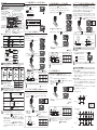
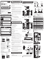
3.米国を除く諸外国へ輸出する場合
米国以外の地域については、警告ラベルまたは説明ラベルを付属品の英文ラベルに貼替えてください。
スマートセンサ
ZX1-LD□□
・形ZX1-LD□□Lセンサ
説明ラベル
分解しないでください。分解すると、
レーザ光がもれ出し視力障害を
起こす恐れがあります。
レーザに関する警告ラベルまたは説明ラベルをセンサ側面に貼っています。
・形ZX1-LD□□Lセンサ
説明ラベル
レーザ光
ビームをのぞきこまないこと
クラス2レーザ製品
Max. 1.0mW 2.5ms
半導体レーザ 660nm
JIS C 6802 : 2011
・FDA証明ラベル
・ラベルを貼る位置
・形ZX1-LD□□
レーザ警告ラベル
・形ZX1-LD□□L
説明ラベル
FDA証明ラベル
パッケージ内容の確認
-1-
14.23
10.5
2.4
3.2
37.8
52.5
46.1
16.7
42.3
A*
10.2
11.7
■形ZX1-LD300□/形ZX1-LD600□
13.6
1-3
ビニール絶縁丸型ロボットコード
φ6.5 9芯(導体断面積0.125mm2/絶縁体径φ0.7mm)
標準長さ2m
根元部曲げ不可長さ:0mm
最小曲げ半径:39mm
投光中心位置マーク
*形ZX1-LD50□の場合、L=50、A=21°
形ZX1-LD100□の場合、L=100、A=11.5°
コード色
投光中心位置マーク
投光軸
基準面
1.9
50.1
27.2
4.5
45.6
2-φ4.5
(取り付け穴)
21.3
基準面
配線について
外部入出力の各コードの機能は次のとおりです。
3
3
基準面
名称
受光軸
50.3
57
66
投光軸
・センサ 1台
・取扱説明書(本書) 各1部(日本語、英語)
・FDA証明ラベル 1枚
・レーザ警告ラベル 各1枚(和文、英文)
(形ZX1-LD□□Lにはレーザ警告ラベルの代わりに説明ラベルが付属します)
13.6
投光中心
L*
15.5
ビニール絶縁丸型ロボットコード
φ6.5 9芯(導体断面積0.125mm2/絶縁体径φ0.7mm)
標準長さ2m
根元部曲げ不可長さ:0mm
最小曲げ半径:39mm
投光中心位置マーク
*形ZX1-LD300の場合、L=300,A=6.6°
形ZX1-LD600の場合、L=600,A=3.4°
<コネクタ中継タイプの場合>
電源
DC10∼30V(リップル(p-p)10%含む)の電源を接続します。
PNPタイプの場合、
アナログ出力以外の入出力のコモン端子となります。
青
GND
電源用0V接続線です。NPNタイプの場合、アナログ出力
以外の入出力のコモン端子となります。
白
緑
OUT1判定出力 CH1の判定結果を出力します。
OUT2判定出力 CH2の判定結果を出力します。
黒
アナログ出力
測定の結果に応じた電流を出力します。(4∼20mA)
橙
桃
紫
TUNE1入力 チューニングをCH1に対して行います。
TUNE2入力 チューニングをCH2に対して行います。
ゼロリセット入力 ゼロリセットの実行、または解除を行います。
赤
LD-OFF入力
ON状態にするとレーザ点灯(発光)が停止します。
この状態では、アナログ出力、デジタル表示、判定出力、
判定出力表示はキープ機能の設定にしたがって出力します。
表示
・コード引き出しタイプとコネクタ中継タイプの各コード色、機能は同様です。
配線は正しく行ってください。空き線は絶縁処理してください。故障の原因になります。
■形ZX1-LD50□□6/形ZX1-LD100□□6
形ZX1-LD300□□6/形ZX1-LD600□□6
<延長コード>
機能
茶
アナログ出力用0V接続線です。
シールド アナログGND 青(OV)のGNDとは分離して接続してください。
【重要】アナログ出力を使用しない場合でも、必ず青(0V)に接続してください。
17
10.1
段差部で、異常な値を
検出する場合があります。
*レーザ光が反射しにくいように壁面をつや消しの色で塗るか、背景除去機能をON設定にして、
チューニングを実施し試してください。
「④詳細設定編 5. 背景除去機能」
7
投光中心
L*
■入出力段回路図<NPNタイプ>
茶 DC10∼30V
ビニール絶縁丸型ロボットコード
φ6.5 9芯(導体断面積0.125mm2/絶縁体径φ0.7mm)
標準長さ0.5m
センサ根元部曲げ不可長さ:0mm
コネクタ部曲げ不可長さ:40mm
最小曲げ半径:39mm
39.8
37.3
負
荷
白 OUT1 判定出力
負
荷
DC10∼30V
緑 OUT2 判定出力
青 GND (0V)
L*
橙 TUNE1入力
内
部
回
路
*L長さは以下の通りです。
形ZX0-XC10R:10m、形ZX0-XC20R:20m
桃 TUNE2入力
紫 ゼロリセット入力
赤 LD-OFF 入力
延長コードはセンサ本体のコード同様にロボットコードになります。
1-2
電流出力
4∼20mA
センサの取り付け
形ZX1-LD50□,形ZX1-LD100□はM3ネジ(締め付けトルク:0.5N・m)で、形ZX1-LD300□,形
ZX1-LD600□はM4ネジ(締め付けトルク:1.2N・m)で確実に取り付けてください。
黒 アナログ出力
シールド アナログGND
負荷 300Ω以下
■入出力段回路図<PNPタイプ>
<取り付け穴寸法(単位:mm)>
茶 DC10∼30V
投光部・受光部方向
基準面
基準面
3
2-M 0.5
P=
23.6±0.1
35.3±0.1
形ZX1-LD50□
形ZX1-LD100□
4.5±0.1
レーザが直接、
または鏡面の物体に反射して、
目に入らないように
ご注意ください。
レーザから放射されたレーザ光はパワー密度が高
く、
目にはいると失明する恐れがあります。
10.1
基準面
4
2-M 0.7
P=
基準面
白 OUT1 判定出力
緑 OUT2 判定出力
DC
10∼30V
負
荷
負
荷
青 GND (0V)
61.5±0.1
警告
段差部でも安定した検出が
可能です。
投光軸
3.2±0.1
・形ZX1-LD□□センサ:クラス2 / 形ZX1-LD□□Lセンサ:クラス1
2.米国へ輸出する場合
本装置を機器に搭載して米国へ輸出する場合、
米国FDA(Food and Drug Administrarionの
規制)のレーザ規制を受けます。形ZX1シリーズ
は、本規格のLaser Notice NO.50の規定に
従いIEC/EN60825-1の基準にてClass1また
はClass2に分類され、CDRH(Center for
Devices and Radiological Health)に届出済
みです。
Accession Number
(形ZX1-LD□□ : 1210041-000)
(形ZX1-LD□□L : 1210041-001)
米国へ輸出の際は、警告ラベルまたは説明ラベ
ルを付属品の英文ラベルに貼替えるとともに
FDA証明ラベルを右図に示している位置に正
しく貼ってください。
使用上の注意
製品が動作不能、誤動作、
または性能・機器への悪影響を防ぐため、以下のことを守ってください。
■設置場所について
次のような場所には設置しないでください
・周囲温度が定格の範囲を越える場所
・急激な温度変化により、結露が発生する場所
・相対湿度が35∼85%RHの範囲を超える場所
・腐食性ガス、可燃性ガスがある場所
・塵埃、塩分、鉄粉がある場所
・振動や衝撃が直接加わる場所
・強い外乱光
(レーザ光、
アーク溶接光など)
があたる場所
・直射日光があたる場所や暖房器具のそば
・水・油・化学薬品の飛沫がある場所
・強磁界、強電界がある場所
・水中・降雨中および屋外
■電源および配線について
・センサの入出力線の配線を確認してから電源を供給してください。
・市販のスイッチングレギュレータをご使用の際は、FG端子を接地してください。
・電源ラインにサージがある場合、使用環境に応じてサージアブソーバを接続してご使用ください。
・配線後は電源を投入する前に、電源の正誤、負荷短絡などの誤接続の有無、負荷電流の適否
について確認を行ってください。誤配線などで故障するおそれがあります。
・コードの延長は別売の延長コード
(ZX0-XC□R)
をご使用ください。
またいずれか1本のみでご使
用ください。
センサのコードの延長は全長で20m以内としてください。
・電源投入から約2.5秒後に表示・点灯します。
■ウォームアップについて
・電源投入後、30分以上経過してからご使用ください。電源投入直後は回路が安定していません
ので計測値が徐々に変化することがあります。
また、長時間LD-OFFを使用した場合も
LD-OFF解除後に30分以上のウォームアップを行ってください。
■保守点検について
・調整や着脱を行う場合は、必ず電源を切ってから作業をしてください。
・清掃には、
シンナー、
ベンジン、
アセトン、灯油類は使用しないでください。
・センサ前面のガラス面に、大きなゴミやホコリが付いた場合は、
ブロアブラシ(カメラレンズ用)で吹き飛
ばしてください。呼気で吹き飛ばすことは避けてください。小さなゴミやホコリは柔らかい布(レンズク
リーナーなど)にアルコールを少量含ませて、
ていねいにふき取ってください。強くふくことは避けてく
ださい。
ガラス面に傷がつくと、誤差の原因になります。
■対象物について
対象物の材質・形状によって、測定できない場合や精度が出ない場合があります。
(透明な部材、
反射率の極端に小さな材質。
スポット径よりも小さな対象物、曲率の大きな対象物、大きく傾斜した
対象物など)
● 警告表示
受光軸
49.3±0.1
1.国内で使用する場合
JIS C6802規格で、
レーザ製品のクラスに応じて使用者が行わなければならない安全予防対
策が規定されています。
2.5
10.2
レーザ機器に関しては、国内・外でレーザ安全対策が規定されています。国内で使用される場合、
国内にて組付けられて海外輸出される場合、
これらを3つのケースにわけて説明します。
18.7
基準面
15.1
A*
レーザ製品を安全に使用していただくために
35.3
Ø 15.5
●分解禁止
機器を分解することで、感電などの障害が起こる可能性を示します。
(取りつけ穴)
22
●レーザ光線
レーザ光線による危害が生じる可能性を示します。
2-φ3.2
2
47
24.1
10.5
投光部や受光部をふさぐと
検出できません。
迷光の影響を受けやすく、
検出値がばらつく場合があります。*
<段差のあるワークを検出する場合>
7
● 図記号の意味
迷光の影響を受け
にくくなります。
投光軸
Ø 15
正しい取扱いをしなければ、この危険のために、軽傷・中程度の
傷害を負ったり、万一の場合には重傷や死亡に至る恐れがありま
す。また、同様に重大な物的損害をもたらす恐れがあります。
以下に示すような項目は安全を確保する上で必要なことですので必ず守ってください。
■設置環境について
・引火性、爆発性ガスの環境では使用しないでください。
・操作や保守の安全を確保するため、高電圧機器や動力機器から離して設置してください。
■電源および配線について
・定格電圧
(DC10∼30V リップル
(p-p)
10%含む)
を越えて使用しないでください。
・電源の逆接続および交流電源への接続はしないでください。
・オープンコレクタ出力は、負荷を短絡させないでください。破損・発火の恐れがあります。
・負荷の接続を正しく行ってください。負荷を短絡させると、破損・発火の恐れがあります。
・負荷は定格以下でご使用ください。破損・発火の恐れがあります。
・高圧線、動力線と当製品の配線は別配線としてください。同一配線あるいは同一ダクトにすると誘
導を受け、誤動作あるいは破損の原因になることがあります。
・配線やコネクタを着脱するときは、必ず電源を切ってから行ってください。
・原子力や人命にかかわる装置への安全回路には使用しないでください。
・フェールセーフ回路などの安全対策を講じてください。
■設置について
・取付けにおいて、
ねじの締め付けは規定のトルク以下で確実に行ってください。
規定のトルク M3:0.5N・m (ZX1-LD50□□/ZX1-LD100□□)
M4:1.2N・m (ZX1-LD300□□/ZX1-LD600□□)
■その他
・本体の分解、修理、改造、加圧変形、焼却などは絶対にしないでください。
・廃棄するときは、産業廃棄物として処理してください。
・万が一、異常を感じたときには、
すぐに使用を中止し、電源を切った上で、
当社支店・営業所までご
相談ください。
投光中心位置マーク
基準面
10.7
* 0 1 9 9 5 6 0 - 4 D *
● 警告表示の意味
警告
<穴の中の検出>
(単位:mm)
安全上の要点
安全上のご注意
・形ZX1-LD□□センサ
レーザ警告ラベル
<壁面付近での検出>
■ヨーロッパへの輸出
形ZX1-LD□□はEN60825-1規格に定めるClass2、
形ZX1-LD□□LはEN60825-1規格に定めるClass1に分類されます。
このたびは、本製品をお買い上げいただきまして、まことにありがとうございます。
ご使用に際しては、次の内容をお守りください。
・ 電気の知識を有する専門家がお取り扱いください。
・この取扱説明書をよくお読みになり、十分にご理解のうえ、正しくご使用ください。
・この取扱説明書はいつでも参照できるよう大切に保管してください。
警告
外形寸法図
基準面
取扱説明書
2011 All Rights Reserved.
1-1
■取り付け時の向きの注意点
■形ZX1-LD50□/形ZX1-LD100□
レーザ変位センサ CMOSタイプ
© OMRON Corporation
設置編
55.8
形
・形ZX1-LD□□センサ
レーザ警告ラベル
(クラス2警告/レーザ放出開口ラベル)
1
橙 TUNE1入力
内
部
回
路
30.1±0.1
45.6±0.1
桃 TUNE2入力
紫 ゼロリセット入力
赤 LD-OFF 入力
形ZX1-LD300□
形ZX1-LD600□
センサの投光部、受光部には触れないでください。指紋などが付着すると、正しく
測定できなくなります。誤って触れた場合は、使用上の注意の保守点検に従い、拭
き取ってください。
-2-
電流出力
4∼20mA
黒 アナログ出力
シールド アナログGND
負荷 300Ω以下
2
(1)しきい値を設定するチャンネルを切り替えたい !
設定編
2-1
● CH 設定モード
操作・表示早見表
1. 測定モードで
2.
【LD ON】
レーザ点灯 表示灯(緑)
【ST】
スマートチューニング表示灯(青)
【ZERO】
ゼロリセット表示灯(橙)
背景除去機能がON設定でチューニングを行ったときに
点灯します。
ゼロリセット設定時に点灯します。
【TUNE】
ボタン
OUT1出力表示灯(橙)
チューニングを実施します。
しきい値1を超えた場合、
もしくは、
しきい値1L∼1H
範囲内の場合に点灯します。
【DOWN】
ボタン
しきい値や設定項目を
変更します。
UP/DOWN
UP/DOWN
ボタン +
UP/DOWN
1. ワークがない状態で
けます。
ch1l
ch2h
しきい値 1L
しきい値 2H
「③(1)」
ボタン同時押し 3 秒以上
「③(1)」
ボタン同時押し 3 秒以上
「③(2)」
0.00
ボタンを押すと、測定モードに戻ります。
3. 検出させたい下限にワークを設置して
MODE
2-2
OUT1 出力
pnt 2
画面が「 」→「 1 」→「 」に変わります。
(近)
しきい値
1
(遠)
ON
OFF
しきい値
2
ON
しきい値
1H
OFF
しきい値
1L
上記は出力極性 [
]が
ノーマルオープン [ ]( 初期値 )
の場合の動作です。
ノーマルクローズ [ ] に設定
した場合、上記の ON/OFF は反転します。
2-3
OUT1 出力
測定値
測定値
測定値
CH1
ボタンをもう一度押します。
ON
OFF
設定完了
OFF
センサ
ON
しきい値
2L
OFF
しきい値
背景 ( 基準面 )
D
0.2
0.7
3
15
単位 : (mm)
ワークの順序はどちらが先でもかまいません。
OFF
D
背景 ( 基準面 )
0.13
0.4
(5)± で公差を設定したい !
1つの実ワークを用いて、それを基準に上限と下限を持たせて範囲内にあるかどうかを判別するとき
に用います。
2. 検出したいワークがある状態で
ボタンを「
」が点滅するまで(3 秒以上 5 秒
TUNE
未満)押し続けます。
3.「
」が点滅したら
ボタンから指を離します。
⑤ エラーメッセージ」
「
」が点滅
するまで
3∼5秒長押し
1. ワークがない状態で
ボタンを「
TUNE
押し続けます。
」点滅するまで(3 秒以上 5 秒未満)
しきい値
画面が「
」 「t-p1」に変わり、1 点エリアチューニングを完了し、測定値表示
に戻ります。
3∼5秒長押し
TUNE
t-p1
ボタンを 5 秒以上押す
・チューニング種別を変更すると
ボタンや外部入力端子の割付を固定することができます。
TUNE
」が点滅したら
「④ 詳細設定編 2. チューニング種別」
ボタンから指を離します。
TUNE
」 「t-p1」に変わり 1 点チューニングを完了し、測定値表示に戻り
設定完了
各形式のしきい値に持たせる
余裕度 (D) は、以下の値です。(固定値)
センサ
・背景除去機能を ON に設定し、チューニングを実行すると、チューニング時の感度に合わせ
て測定値、感度の制限を行うことができます。周囲の壁などでの乱反射による異常な距離が
検出されるときにご使用ください。
・チューニングを行うと、センサ内部の EEPROM( 不揮発性メモリ ) にしきい値を記録します。
この EEPROM の書込み寿命は10万回です。測定ごとのチューニングは寿命にも気をつけて
お使いください。
-3-
OFF
形式
D
ON
「④ 詳細設定編 5. 背景除去機能」
(ワークなし)
しきい値
背景 ( 基準面 )
D
ZX1ZX1ZX1ZX1LD50□□ LD100□□ LD300□□ LD600□□
0.2
0.7
3
D
しきい値 H
ON
OFF
ワーク
判定出力
ON
OFF
動作点
復帰点
各形式の上限・下限に持たせる
余裕度 (D) は、以下の値です。(固定値)
センサ
OFF
D
しきい値 L
背景 ( 基準面 )
形式
D
エリア出力 ON の時
ZX1ZX1ZX1ZX1LD50□ LD100□ LD300□ LD600□
0.13
0.4
2
ヒステリシス幅
測定値
設定完了
TUNE
2 点目で ボタンを一回押す
画面が「
ます。
エリア出力のON/OFFによって、しきい値に対してヒステリシス幅が設定さ
れる方向が異なりますのでご注意ください。
t-p1
「
」が点滅
するまで
2.「
判定出力がOFFからONに変化する点を動作点、ONからOFFに変化する点を復帰
点といいます。この動作点と復帰点の間の距離をヒステリシス幅といいます。本
センサではしきい値=動作点となっており、ヒステリシス幅により復帰点までの
距離を設定することができます。
エリア出力 OFF の時
1 点目で ボタンを一回押す
「2-3(5)」
●ヒステリシス幅とは
1. メニューの AREA 項目で ON を設定し、測定値表示に戻ります。
背景 ( 基準面 ) がすでに決まっており、それを基準にワークのありなしを判別するときに用います。
・ボタンの代わりに外部入力端子である TUNE1 入力でも、同様に CH1 に対して
チューニングすることができます。
TUNE2 入力の場合でも CH2 に対してチューニングすることができます。
ヒステリシス幅の微調整
ワークに応じてヒステリシス幅を小さく調整することで微小な段差の判別ができ
ます。ただし、ワークが動いていたり、反射光量が小さいなどの要因により変位
値が変動している場合にヒステリシス幅を小さくすると、判定出力がばたつくこ
とがありますのでご注意ください。
TUNE
「
0.00
●ヒステリシス幅の設定
「④ 詳細設定編 7. エリア出力」
● 1 点エリアチューニング
ボタンで
:しきい値が小さくなります
9
● 1 点チューニング
ボタンか
ボタンを 3 ∼ 5 秒押す
ワークなしチューニング
2
:しきい値が大きくなります
UP/DOWN
「しきい値 1/ しきい値 1H/ しきい値 1L」変更中は OUT1 出力表示灯が点滅します。
「しきい値 2/ しきい値 2H/ しきい値 2L」変更中は OUT2 出力表示灯が点滅します。
(3)ワークのあり / なしを検出したい !( 基準面だけでチューニング )
ボタンのいずれかで設定する CH を選択します。
「2-3(2)」「2-3(3)」
ワーク
(ワークなし)
ZX1ZX1ZX1ZX1LD50□□ LD100□□ LD300□□ LD600□□
ON
ボタンを押し CH 設定モードに入ってから、
2 点チューニング
形式
D
OFF
検出時の出力
各形式のしきい値に持たせる
余裕度 (D) は、以下の値です。(固定値)
センサ
ON
MODE
「2-3(1)」「2-3(4)」
しきい値 L
しきい値の微調整
ZX1ZX1ZX1ZX1LD50□ LD100□ LD300□ LD600□
2-5
■チューニング操作早見表(CH1/CH2 の選択後にチューニングを実施します。)
1 点チューニング
D 下限ワーク
形式
OUT2 出力
チューニングする
CH 設定モード
しきい値 H
背景 ( 基準面 )
しきい値 L
ON
ON/OFF が切り換わる条件を緩めたり厳しくする場合、
しきい値を微調整することができます。
ワークの順序はどちらが先でもかまいません。
t-p2
しきい値
2H
出力極性
上限ワーク
OFF
測定値
OFF
D
OFF
ON
CH2
背景 ( 基準面 )
● しきい値設定
各形式の上限・下限に持たせる
余裕度 (D) は、以下の値です。(固定値)
センサ
センサ
<エリア出力 ON の時>
OUT2 出力
2-4
設定完了
しきい値 H
OFF
しきい値
OFF
画面が「
」→「2 pnt」に変わり、2 点エリアチューニングを完了し、
測定値表示に戻ります。
「2-4」
CH2
ON
t-p1
出力としきい値の関係
CH1
センサ
ON
t-p2
しきい値設定モード
<エリア出力 OFF の時>
<ワークなしエリアチューニング>
センサ
ボタンを押します。
TUNE
設定完了
ボタンから指を離します。
TUNE
TUNE
2. ワークがある状態で
1 秒未満
」が高速点滅したら
<ワークなしチューニング>
1. ワークがない状態で
メニュー設定モード
UP/DOWN
2. 「
ボタンを 1 回短く押します。
良品と不良品、ワークと背景 ( 基準面 )、ワーク A とワーク B のように、異なる高さとなるものを
判別するときに用います。
「2-3(1)」
3 秒以上
長押し
pnt 2
画面が「 」→「 1 」→「 」に変わります。
CH 設定モード
MODE
「
」が高速
点滅するまで
5秒以上長押し
MODE
3 秒未満
」が高速点滅するまで(5 秒以上)押し続
しきい値 2L
■各モードへの切り替え方法
測定モード
ボタンを「
TUNE
t-p1
ch2l
● 2 点チューニング
ボタン同時押し 3 秒未満
TUNE
キーロック設定 / 解除
基準となる面との距離に上限と下限を持たせ、範囲内にあるかどうかを判別するときに用います。
2 点エリアチューニングと異なり、ワークなしであることを基準に判定しますので、ワーク形状が
複雑で受光量不足エラーや計測範囲外エラーになる場合であってもワークありとして判別します。
TUNE
TUNE
ボタン +
● ワークなしエリアチューニング(エリア出力 ON の場合)
ボタンを押します。
TUNE
MODE
TUNE
ゼロリセット解除
しきい値 2
3.
「2-3」
ボタン
ボタン +
しきい値 1
2. 検出させたい上限にワークを設置して
(2)ワークのあり / なしを検出したい !
測定モードでは変位量、その他のモードで
は設定項目 / 設定値を表示します。
■その他のボタン操作
チューニング実行
3 秒以上長押しすることで、
測定モードとメニュー設定
モードを切り替えます。
3 秒未満押すことで
CH 設定モードに切り替え
ます。
デジタル表示
しきい値や設定項目を
変更します。
ch-2
しきい値 1H
【MODE】
ボタン
【UP】
ボタン
ch-1
ch1h
OUT2出力表示灯(橙)
1. メニュー設定モードのエリア出力で ON を選択して、測定モードに戻ります。
<エリア出力 ON の場合>
88888
....
しきい値2を超えた場合、
もしくは、
しきい値2L∼2H
範囲内の場合に点灯します。
ボタンを押すことで、
UP/DOWN
背景 ( 基準面 ) がすでに決まっており、それを基準にワークのありなしを判別するときに用います。
1 点チューニングと異なり、ワークなしであることを基準に判定しますので、ワーク形状が複雑で
受光量不足エラーや計測範囲外エラーになる場合であってもワークありとして判別します。
上限ワークと下限ワークを使って、範囲内にあるかどうかを判別するときに用います。
以下の順に切り替わります。
センサがレーザを投光しているときに点灯します。
メニュー設定モード時に点灯します。
● ワークなしチューニング(エリア出力 OFF の場合)
「④ 詳細設定編 7. エリア出力」
● 2 点エリアチューニング
ch-1
MODE
■各部の名称とはたらき
【MENU】
メニュー表示灯(橙)
ゼロリセット設定
ボタンを 1 回短く押します。
(6)
「(2)∼(5)」の方法でうまく設定できなかった場合は?
(4)上限と下限を設定したい !(エリア出力を使う)
測定値
9
しきい値 H
単位 : (mm)
背景 ( 基準 ) をゼロとして、プラスマイナスいくらかのしきい値を設定したい場合は、
まずゼロリセットをして、ワークとの距離をゼロにしてから 1 点エリアチュー
ニングを実行してください。
「
便利な設定編 (1)」
③
15
単位 : (mm)
-4-
しきい値 L
判定出力
ON
OFF
ヒステリシス幅
3
4
便利な設定編
(1)今の距離を“0”にしたい !
測定モードで
ボタンを 3 秒以上長押しするとメニュー設定モードとなります。
メニュー設定モードでは以下の機能設定ができます。項目設定から
ボタンと
TUNE
機能の設定
ボタンと
C
機能の説明
UP/DOWN
現在値が“0”になります。ゼロリセット設定時には、
ゼロリセット表示灯が点灯します。
1.23
設定完了
3 秒長押し
ボタンと
または
TUNE
ボタンと
ボタンを
MODE
3 秒長押し
ボタン
3 秒以上長押し
解除されます。
ボタンの代わりに外部入力端子であるゼロリセット入力を
3 秒以上 ON することでゼロリセットを解除することができます。
設定解除
A
(2)誤操作を防ぎたい !
ボタンと
または
ボタン、
MODE
ボタンと
3 秒以上押します。
l c
ボタンを同時に
MODE
3 秒以上長押し
● キーロック解除
1. キーロック設定後に
ボタン、または
ボタンと
ボタンと
2.チューニング種別
l c
UP/DOWN
MODE
ボタン
MODE
を同時に 3 秒以上押すとキーロック解除します。
キーロックは電源再投入後も保持されます。
MODE
3 秒以上長押し
ON 時
OFF 時
T
ON
OFF
6. ヒステリシス幅
UP/DOWN
オン・オフ
ディレイ
ヒステリシス幅を設定します。
判定出力が境界付近で不安定にならないよう
しきい値にヒステリシス幅を設けています。
標準設定:
ヒステリシス幅に
初期値を設定します。
チューニング方式を選択します。
時間識別以外を選択するとチューニング方式
が固定になります。
時間識別:入力時間で設定
*2:ON 時間<タイマ値の場合、ON しません。
8. エリア出力
エリア出力使用 / 不使用を選択します。
UP/DOWN
エリア出力を使わない
UP/DOWN
ユーザー設定:
任意の
ヒステリシス幅を
設定します。
「②設定編 2-3」
MODE
エリア出力を使う
測定値がしきい値 L ∼しきい値 H の範囲
に入った時、ON します。
MODE
初期値
MODE
OFF
設定可能範囲
LD50
0.07mm
0.00∼10.00mm
LD100
0.3mm
0.00∼35.00mm
LD300
1mm
0.0∼150.0mm
LD600
6mm
0.0∼400.0mm
高速モード:10ms
最速モード:1ms
両出力とも OFF
OFF
センサ
ワーク
しきい値 H
ワーク
しきい値 L
ワーク
・ワークなしエリアチューニングを実行
した後は ON と OFF が反転します。
・エリア出力の設定は、CH1、CH2 が
同時に切り替わります。
9. ゼロリセットメモリ
UP/DOWN
電源を切っても、ゼロリセットしたときの
測定値を保持するかどうかを設定します。
ゼロリセットメモリ無効
MODE
ゼロリセットメモリ有効
)
や
ゼロリセットメモリを「ON」にしておくとゼロリセットするた
びにセンサ本体内部の EEPROM( 不揮発性メモリ ) に書き込まれ
ます。この EEPROM の書込み寿命は 10 万回です。
測定ごとの書込は故障の原因となりますので、「ON」で使用す
る場合は書込寿命にご注意ください。
出力内容
OUT1/OUT2 出力
ON
センサ
OFF
より安定して検出するのためにも応答速度
を長く設定いただくことを推奨します。
MODE
OFF
センサ
ON
ヒステリシス幅を小さく調整することで微小
な段差の判別にも対応させることができます。
ただし、反射光量の小さい場合は、反映出力
が不安定になる場合がありますのでご注意願
います。
標準モード:100ms
計測エラー時
(
、
、
計測確定前の出力内容を設定します。
*1
*1
*2
*2
*3:出力中に OFF→ON 条件を満たしても無視します。
(単位:mm)
応答時間を設定します。
UP/DOWN
T
T
ON
OFF
T=タイマ値
UP/DOWN
4. キープ機能
*3
*3
T
T
*1:OFF 時間<タイマ値の場合、OFF しません。
MODE
1 点チューニング
MODE
T
*2
*2
T
ワンショット
ワークなしチューニング
3. 応答時間
*1
*1
T
OFF
検出時の出力 ON/OFF を選択します。
メニューと同時に出力に反映されます。
2 点チューニング
設定解除
MODE
出力 ON/OFF を共に遅らせます。
OFF
「2-2 出力としきい値の関係」
設定完了
9999
オン・オフディレイタイマ
オフディレイ ON
ノーマルオープン:センサ出力 OFF 時、
出力端子がオープン
になります。
ノーマルクローズ:センサ出力 OFF 時、
出力端子がクローズ
になります。
MODE
MODE
ワークの大きさがばらつく
場合でも、一定時間出力します。
オンディレイ ON
UP/DOWN
UP/DOWN
ワンショットタイマ
:初期値
測定モードにおけるボタン操作を禁止することができます。
1.
検出してから出力 ON を遅ら
せます。
1. 出力極性
● キーロック機能
1
オンディレイタイマ
1.23
<メニュー設定モード>
(単位:msec)
検出時間が短く、PLC で検出が
できない場合、出力 ON を保持
します。
スマートチューニング
表示灯
TUNE
を同時に 3 秒以上押すと、ゼロリセットは
オフディレイタイマ
背景除去機能は、設定を ON に変更した後に
チューニングを行うことで有効となります。
感度の制限範囲からはずれた時には
または
になります。
スマートチューニング表示灯 ( 青色 )
が点灯することで確認可能です。
同時に 3 秒以上長押しします。
MODE
タイマ機能を使用しません。
MODE
チューニング時の感度に合わせて以降の
測定値、感度の制限を行います。
UP/DOWN
ボタンのいずれかと
1 秒後
0.00
ボタン、
UP/DOWN
MODE
キーロックを解除するには
set
● ゼロリセット解除
1.
キーロック中は以下の画面が表示
され、設定モードに入れません。
1 秒後
MODE
ボタンの代わりに外部入力端子であるゼロリセット入力を
4ms 以上 3 秒未満 ON することでゼロリセットを行うことができます。
タイマ動作時間を設定します。
チューニング時のワークにのみ感応する
ようにします。
感度の制限を行いません。
TUNE
を同時に 1 回短く押します。
機能の説明
7. タイマ機能
<測定モード>
0.00
ボタン
機能の設定
5. 背景除去機能
とで、次の項目メニューに移ります。
また、全ての設定は CH1、CH2 で共通に適用されます。
ボタン
機能の説明
B
ボタンを押下するこ
MODE
現在の値を“0”にします。
または
機能の設定
MODE
● ゼロリセット
1.
詳細設定編
アナログ出力
10. エコ機能
クランプ値
(22mA)
を
出力
UP/DOWN
距離検出不能と判断する直前の検出値を出力
消費電力を少なくしたい場合や具体的な
値を表示したくない場合に設定します。
エコ機能無効
MODE
ワークなしチューニング時は、キープ機能は動作しません。
エコ機能有効
エコ機能を有効にした場合、RUN モード
中に 30 秒間操作を行わないとエコ表示
となり、デジタル表示が消灯します。
エコ表示中はいずれかのボタン操作
で通常表示に戻ります。
11. 設定初期化
UP/DOWN
すべての設定内容を工場出荷時の状態
に戻します。
設定初期化キャンセル
MODE
この表示の時に
B
-5-
ボタンを押すと
MODE
C
A
-6-
設定初期化を実行します。
5
7
エラーメッセージ
ここでは、
デジタル表示に表示されるエラー内容とその処置について記載します。
原因
エラー名/表示
e-ld
システムエラー
e-5y5
EEPROMエラー1
e-me1
EEPROMエラー2
センサが故障してい
ます。
センサ設定メモリが
異常です。
センサ設定メモリが
異常です。
e-me2
負荷短楽検知エラー
トラブル
処置
レーザダイオードが
劣化しています。
LD故障エラー
応答時間をより遅い設定に変更してから、再度チュー
ニング実施してください。
センサとワークの距離が測定範囲内か確認後、再度
実施してください。
光量不足エラー
受光量が不足してい
ます。
応答時間を遅くするか、
センサ本体とワーク間の距離をセンサが検出で
きるように調整してください。
背景除去機能の動作中は、制限感度以下の受光量になっています。
光量飽和エラー
受光量飽和による
計測異常です。
正反射光がセンサに入らないようにしてください。
背景除去機能の動作中は、制限感度以上の受光量になって
います。
e-brt
e-%Ur
6
形式
稼動中に再起動される
原因
エコ機能が ON になって
いませんか?
電源が入っていないか、断線
していませんか?
レーザ光が投光されない
LD-OFF入力が短絡していま
」
が表示される せんか?
画面に「
入力信号を受け付けない
各コードが正しく接続されていない
か、断線の可能性があります。
対応方法
エコ機能を OFF してください。
「④ 詳細設定編」
配線の見直し、電源電圧・電源
容量の見直しを行ってください。
「① 設置編 1-3」
配線の見直しを行ってください。
「① 設置編 1-3」
配線の見直しを行ってください。
「① 設置編 1-3」
測定値が日や時刻によって 温度特性の影響が考えられます。ウォーミングアップを30分以上
変動し安定しない
行ってください。定期的に基準
対象物でゼロリセットを実行し、
補正するようにしてください。
ンを3秒長押しすることにより、設定内容を初
MODE ボタ
期化してください。
それでもエラーが解決しない場合は、
センサが故障して
います。センサを交換してください。
チューニングに失敗
しました。
測定範囲外エラー
画面に何も表示されない
いったん電源を切り、
センサが正しく結線されているか
確認後、電源を再投入してください。
それでもエラーが
解決しない場合は、
センサが故障しています。センサを
交換してください。
いったん電源を切り、
白OUT1/緑OUT2の出力線が
短絡していないか確認後、電源を再投入してください。
e-tUn
デジタル表示がされない
いったん電源を切り、
センサが正しく結線されているか
確認後、電源を再投入してください。
それでもエラーが解決しない場合は、
センサが故障して
います。センサを交換してください。
判定出力線が短絡し
ています。
チューニング実行エラー
メンテナンス編:トラブルシューティング
ここでは、
ハードに関する一時的なトラブルの対処方法を記載しますので、
ご確認ください。
画面に
「
される
」
が表示
検出距離が長く、測定範囲外
になっていませんか?
投受光面がほこり汚れや冶具
などで遮蔽されていませんか?
センサの設置環境を見直して
ください。
OUT1表示灯/OUT2表示灯 他センサによる相互干渉が発生 他センサのレーザ光線の光路や
反射した迷光の影響を受けない
している可能性があります。
が点滅する
よう、設置環境を見直してください。
キープ機能「
OUT1表示灯/OUT2表示灯 キープ機能「
」=「 」で、
が計測範囲外にもかかわらず かつ、受光量不足「
」または測定 にしてください。
点灯し続ける
範囲外「
」の場合が考えられます。
」=「
」
」=「 」に
このような現象 背景除去機能「
明らかに測定範囲外の領域 センサの特性上、
してチューニングを行ってください。
で、異常な距離が検出される が発生する場合があります。
「④ 詳細設定編」
検出物体との測定距離を確認のうえ、
使用してください。
測定値が計測範囲外 センサ本体とワーク間の距離を測定範囲内に設置し
です。
てください。
初期設定に戻したい
設定初期化を行ってください。
「④ 詳細設定編」
−
定格/仕様
NPN
出力
コード引き出しタイプ
形ZX1-LD
50A61
形ZX1-LD 形ZX1-LD
100A61
50A61L
コネクタ中継タイプ
形ZX1-LD
50A66
形ZX1-LD
100A66
形ZX1-LD
50A81
形ZX1-LD
50A86
形ZX1-LD 形ZX1-LD
50A81L
100A81
形ZX1-LD
100A86
コード引き出しタイプ
PNP
出力
コネクタ中継タイプ
形ZX1-LD
300A66
形ZX1-LD
600A66
形ZX1-LD 形ZX1-LD 形ZX1-LD
100A81L 300A81 300A81L
形ZX1-LD
300A86
形ZX1-LD
600A81
形ZX1-LD
600A86
52.5mm × 47mm × 24.1mm
50±10mm
100±35mm
外形サイズ
計測範囲
光源(発光波長)
FDA class *2
JIS規格 IEC/EN class
スポット径(代表例)
(検出距離中心にて規定) *1
電源電圧
消費電流
アナログ出力
表示灯
判定出力
応答時間 レーザOFF入力
ZERO入力
使用周囲照度
ウォーミングアップ
リニアリティ*2
温度特性 *3 静止分解能 *4
周囲温度範囲
φ0.33mm
形ZX1-LD
600A81L
ご使用に際してのご承諾事項
66mm × 50.1mm × 27.2mm
300±150mm
600±400mm
可視光半導体レーザ (660nm)
class 2
class 1
class 2
class 1
class 2
class 1
(最大1mW) (最大0.24mW) (最大1mW) (最大0.24mW) (最大1mW) (最大0.24mW)
class 1
class 1
class 1
class 2
class 2
class 2
(最大1mW) (最大0.24mW) (最大1mW) (最大0.24mW) (最大1mW) (最大0.24mW)
φ0.17mm
形ZX1-LD
600A61L
class 2
(最大1mW)
class 2
(最大1mW)
φ0.52mm
①安全を確保する目的で直接的または間接的に人体を検出する用途に、本製品を使用
しないでください。同用途には、当社センサカタログに掲載している安全センサをご使用
ください。
②下記用途に使用される場合、当社営業担当者までご相談のうえ仕様書などによりご確
認いただくとともに、定格・性能に対し余裕を持った使い方や、万一故障があっても危
険を最小にする安全回路などの安全対策を講じてください。
a)屋外の用途、潜在的な化学的汚染あるいは電気的妨害を被る用途
またはカタログ、取扱説明書等に記載のない条件や環境での使用
b)原子力制御設備、焼却設備、鉄道・航空・車両設備、医用機械、娯楽機械、
安全装置、
および行政機関や個別業界の規制に従う設備
c)人命や財産に危険が及びうるシステム・機械・装置
d)ガス、水道、電気の供給システムや24時間連続運転システムなどの
高い信頼性が必要な設備
e)その他、上記 a) ∼ d) に準ずる、高度な安全性が必要とされる用途
*上記は適合用途の条件の一部です。当社のベスト、総合カタログ・データシート等最新版
のカタログ、
マニュアルに記載の保証・免責事項の内容をよく読んでご使用ください。
class 1
(最大0.24mW)
class 1
(最大0.24mW)
φ0.56mm
DC10∼30V
(リップル (p-p) 10%含む)
250mA以下
(電源電圧DC10V時)
電流出力4∼20mA、最大負荷抵抗300Ω
デジタル表示、
出力表示灯(OUT1、OUT2)、
ゼロリセット表示灯、
メニュー表示灯、
レーザ点灯表示灯、
スマートチューニング表示灯
最速(SHS)モード:1ms, 高速(HS)モード:10ms, 標準(STND)モード:100ms
200ms以下
200ms以下
受光面照度
受光面照度 受光面照度
受光面照度 受光面照度 受光面照度 受光面照度 受光面照度
白熱ランプ
白熱ランプ
白熱ランプ
白熱ランプ 白熱ランプ 白熱ランプ 白熱ランプ 白熱ランプ
:7,500lx以下 :5,000lx以下 :7,500lx以下 :5,000lx以下 :5,000lx以下 :2,500lx以下 :5,000lx以下 :2,500lx以下
電源投入後30分のアナログ出力変動 ±0.1%F.S.以下
±0.15%F.S.
±0.15%F.S.
±0.25%F.S. ±0.25%F.S.(Near側)
±0.5%F.S.(全範囲)
±0.03%F.S./℃ ±0.03%F.S./℃ ±0.03%F.S./℃ ±0.04%F.S./℃
2μm
7μm
30μm
80μm
インダストリアルオートメーションビジネスカンパニー 動作時:-10∼+55℃、保存時:-15∼+70℃
(ただし氷結結露しないこと)
動作時・保存時:35∼85%RH(ただし結露しないこと)
周囲湿度範囲
耐電圧
振動
(耐久)
衝撃
(耐久)
●お問い合わせ先
カスタマサポートセンタ
AC1,000V 50/60Hz 1min
10∼55Hz 複振幅1.5mm X、Y、Z各方向2h
500m/s2 X、Y、Z各方向3回
保護構造 *5
標準コード長さ *6
質量
形ZX1-LD 形ZX1-LD 形ZX1-LD 形ZX1-LD
100A61L 300A61 300A61L 600A61
コード引き出しタイプ
(2m)
(梱包状態/本体のみ)コネクタ中継タイプ
(0.5m)
材質
フリーコール
電話
IEC規格 IP67
2m(コード引き出しタイプ)、5m(コード引き出しタイプ) *7、0.5m(コネクタ中継タイプ) *7
約240g/約180g
約270g/約210g
約170g/約110g
約200g/約140g
電話
EC規格適合,RoHS準拠
判定出力
外部入力
残留電圧
ON時
OFF時
NPNオープンコレクタ出力
DC30V 100mA以下
(通話料がかかります)
●FAXによるお問い合わせは下記をご利用ください。
カスタマサポートセンタ お客様相談室 FAX 055-982-5051
PNPオープンコレクタ出力
DC30V 100mA以下
1V以下
(負荷電流≦10mA)
1V以下
(負荷電流≦10mA)
(10mA<負荷電流≦100mA)
2V以下
(10mA<負荷電流≦100mA) 2V以下
電源電圧短絡または電源電圧-1.5V以内
0V短絡または1.5V以下
開放
(漏れ電流0.1mA以下)
開放
(漏れ電流0.1mA以下)
055-982-5002
〔営業のお問い合わせ時間〕
■営業時間:9:00∼12:00/13:00∼17:30 (土・日・祝祭日は休業)
■営 業 日:土・日・祝祭日/春期・夏期・年末年始休暇を除く
*1.スポット径:検出距離中心における中心光強度の1/e2(13.5 %)で定義しています。定義域外にも漏れ光があり、
ワーク周囲の光反射率がワークに
比べて高い状況では、影響の出る場合があります。
また、
スポット径より小さいワークを検出する場合は、正しい計測値が得られない場合があります。
*2.25℃環境下での当社標準対象物
(白セラミック)
測定時における変位出力の理想曲線に対する誤差を示します。
*3.センサとワークの間をアルミの治具で固定した場合の検出距離中心における温度特性。
*4.STNDモード、標準白色セラミックにて、背景除去機能をONに設定し、
チューニングを実施した状態で静止定義。
*5.コネクタ中継タイプのコネクタ部も、延長コードと接続いただくとIP67です。
*6.コネクタ中継タイプ:延長コード10Mもしくは延長コード20Mとセットで使用してください。
*7.形ZX1-LD□□Lは2m
(コード引き出しタイプ)
のみとなります。
定格
055-982-5015 (通話料がかかります)
〔技術のお問い合わせ時間〕
■営業時間:8:00∼21:00
■営 業 日:365日
■上記フリ−コ−ル以外のセンシング機器の技術窓口:
ケース・カバー:ポリブチレンテレフタレート、光学窓:ガラス、
ケーブル:PVC
適合規格
01 2 0 - 9 19 - 0 6 6
携帯電話・PHSなどではご利用いただけませんので、
その場合は下記電話番号へおかけください。
●その他のお問い合わせ先
納期・価格・修理・サンプル・仕様書は貴社のお取引先、
または貴社担当オムロン営業員にご相談ください。
A q 2009年 10月
-7-
-8-
1
PRECAUTIONS FOR SAFE USE
The ZX1-LD has the following WARNING label or explanatory label on the side of the sensors.
・ZX1-LD□□
・ZX1-LD□□L
Laser Warning Label
Explanatory Label
レーザ光
ビームをのぞきこまないこと
クラス2レーザ製品
Max. 1.0mW 2.5ms
半導体レーザ 660nm
JIS C 6802 : 2011
10.5
2.4
3.2
37.8
52.5
46.1
45.6
Reference surface
3
0-V power supply terminal. Used as the common I/Os terminal
for all I/O except monitor output for an NPN output type.
White
Green
OUT1 Judgment output Outputs the CH1 judgment result.
OUT2 Judgment output Outputs the CH2 judgment result.
Black
Analog output
Shield
Analog GND
Orange
Pink
Purple
TUNE1 input
TUNE2 input
Zero reset input
Inputs tuning to CH1.
Inputs tuning to CH2.
Used to execute or cancel zero reset.
Red
LD-OFF input
ON: Laser turns OFF (radiation stop). In this state, analog output, digital
display, judgment output and judgment output display are output based on
keep function settings. The digital display shows [
].
3
21.3
GND
17
57
50.3
22
Receiver
axis
Emitter
axis
13.6
L*
Emitter center
position mark
10.1
Emitter center
15.5
* ZX1-LD300: L=300, A=6.6°
ZX1-LD600: L=600, A=3.4°
<Connector Joint Model>
Vinyl insulated round-shaped robot cable
Dia 6.5 9-wire (cross section of conductor:
0.125 mm2/insulator diameter: 0.7 mm)
Standard length: 2 m
Root section bending disabled length: 0 mm
Minimum bending radius: 39 mm
Outputs the current value according to the measurement result.
(4 to 20 mA)
0-V ground line for monitor output.
Connect this line separately from the blue (0 V) GND.
[Important] Be sure to connect to blue (0 V).
The individual wire colors and roles are the same between pre-wired and
connector joint models.
Wire the Sensor correctly. Unused wires must be insulated. Incorrect wiring may
result in damage to the Sensor.
■ ZX1-LD50□6/ZX1-LD100□6
ZX1-LD300□6/ZX1-LD600□6
■ I/O Circuit Diagram <NPN Output Type>
Brown: 10 to 30 VDC
Vinyl insulated round-shaped robot cable
Dia 6.5 9-wire (cross section of conductor:
0.125 mm2/insulator diameter: 0.7 mm)
Standard length: 0.5 m
Sensor root section bending disabled length: 0 mm
Connector section bending disabled length: 40 mm
Minimum bending radius: 39 mm
39.8
<Extension Cable>
37.3
White: OUT1
judgment output
Green: OUT2
judgment output
L*
10 to 30 VDC
Blue: GND (0 V)
Orange: TUNE1 input
Pink: TUNE2 input
Purple: Zero reset input
* The length of L is as follows:
ZX0-XC10R: 10 m, ZX0-XC20R: 20 m
Red: LD-OFF input
The extension cable is the robot cable, the same as the cable of the Sensor Unit.
Current output
4 to 20 mA
1-2 Mounting Sensor
To mount ZX1-LD50 and ZX1-LD100□, use M3 screws (tightening torque: 0.5 N·m) and
ZX1-LD300□ and ZX1-LD600, M4 screws (tightening torque: 1.2 N·m).
Brown: 10 to 30 VDC
Emitter/Receiver direction
Reference
surface
3
2-M 0.5
P=
Reference
surface
23.6±0.1
35.3±0.1
ZX1-LD50□
ZX1-LD100□
4
2-M 0.7
P=
Reference
surface
Load 300 Ω max.
■ I/O Circuit Diagram <PNP Output Type>
Mounting hole dimensions (Unit: mm)
Reference
surface
Black: Analog output
Shield: Analog GND
White: OUT1
judgment output
Green: OUT2
judgment output
Load
• Sensor: 1
• Instruction sheet (this sheet): 1 each (Japanese and English)
• FDA Certification label : 1
• Laser Warning Label : 1 each (Japanese and English)
(The explanatory labels are attached to ZX1-LD□□L instead of the warning explanation labels.)
(Mounting hole)
Blue
Load
-1-
Checking the Package Content
50.1
27.2
2-4.5 dia.
1.9
Connect to 10 to 30 VDC (including 10% ripple (p-p)). Used as the
common I/Os terminal for all I/O except monitor output for a PNP output type.
10 to
30 VDC
Blue: GND (0 V)
Internal circuit
Using in a country other than U.S.
・For countries other than Japan and U.S., warning labels
or explanatory labels must be replaced by English ones
(supplied with the product). EN60825-1 is provided for
products used in Europe, and the content of this
standard differs.
・The ZX1-LD is categorized as a Class 2 or Class 1
device as stipulated in EN60825-1:2007.
・ZX1-LD□□
When using devices in which ZX1-LD is installed
Laser WARNING label
in the U.S., the devices are subjected to the U.S.
・ZX1-LD□□L
FDA (Food and Drug Administration) laser
Explanatory Label
regulations. ZX1 series is classified into Class2 or
Class 1 by the standard of IEC/EN60825-1
according to deviations of Laser Notice NO.50 of
this standard, and reported to CDRH (Center for
Devices and Radiological Health).
Accession Number
(ZX1-LD□□ : 1210041-000)
(ZX1-LD□□L : 1210041-001)
FDA Certification label
Replace the WARNING label or explanatory label with the corresponding English label and
put the FDA Certification label. (supplied with the sensor)
Please make sure that the label are affixed at the correct locations as indicated.
・ZX1-LD□□L
・ZX1-LD□□
Explanatory Label
Laser Warning Label
(Class2 label / Aperture label)
Reference surface
Role
Power supply
Internal circuit
■ Labeling on Laser Use
10.2
Emitter
axis
Name
Brown
4.5±0.1
The ZX1-LD uses a laser as the light source. Lasers are classified based on EN standard (EN 60825-1)
Wire color
Emitter center position mark
Load
SAFETY PRECAUTIONS FOR USING LASER EQUIPMENT
The table below shows individual external I/O wires and their roles.
Load
Do not disassemble the product. Doing so may cause the
laser beam to leak, resulting in the danger of visual
impairment.
1-3 Wiring
Vinyl insulated round-shaped robot cable
Dia 6.5 9-wire (cross section of conductor:
0.125 mm2/insulator diameter: 0.7 mm)
Standard length: 2 m
Root section bending disabled length: 0 mm
Minimum bending radius: 39 mm
■ ZX1-LD300□/ZX1-LD600□
Reference surface
Detailed Settings"
61.5±0.1
Do not expose your eyes to the laser radiation either directly
(i.e., after reflection from a mirror or shiny surface). Loss of
sight may possibly occur in case of the exposure to laser
high power density.
11.7
* ZX1-LD50□: L=50, A=21°
ZX1-LD100□: L=100, A=11.5°
A*
WARNING
警告
Emitter center
Level difference may cause
an abnormal detection value.
* Before performing tuning, apply mat paint on the wall surface or turn ON the background suppression
function to avoid laser light reflection.
Refer to " 5. Background suppression function,
Ø 15.5
● Alert Statements
Stable detection is possible
regardless of level difference.
7
● Do not disassemble
Indicates prohibition when there is a risk of minor injury from
electrical shock or other source if the product is disassembled.
L*
Emitter center
position mark
10.1
10.5
PRECAUTIONS FOR CORRECT USE
■ Installation Location
Do not install the product in locations subjected to the following conditions:
• Surrounding air temperature outside the rating
• Rapid temperature fluctuations (causing condensation)
• Relative humidity outside the range of 35 to 85%
• Presence of corrosive or flammable gases
• Presence of dust, salt, or iron particles
• Direct vibration or shock
• Reflection of intense light (such as other laser beams, electric arc-welding machines, or
ultra-violet light)
• Direct sunlight or near heaters
• Water, oil, or chemical fumes or spray, or mist atmospheres
• Strong magnetic or electric field
• In the water, rain, or outdoors
■ Power Supply and Wiring
• Do not supply the power to the Sensor before checking the I/O wiring.
• Ground the FG terminal when using a commercially-available switching regulator.
• If the power supply line is subject to surges, connect a surge absorber that meets the conditions
of the operating environment.
• Do not turn ON the power after wiring before making sure that the power supply is connected
correctly; there are no faulty connections, e.g. load short-circuits; the load current is correct.
Incorrect wiring may result in failure.
• Use a ZX0-XC□R Extension Cable (sold separately) to extend the Sensor’s cable. Use only one
cable. Do not extend the cable for the Sensor to a length exceeding 20 m.
• The display and indicators turn ON after approx. 2.5 seconds after the power is turned ON.
■ Warming Up
• After turning ON the power, allow the Sensor to warm up for approx. 30 minutes prior to use.
The circuitry is not stable immediately after turning the power ON, and the values gradually
change until the Sensor is completely warmed up. When using LD-OFF input for a long period
of time, perform warmng up for more than 30 minutes after cancelling LD-OFF.
■ Maintenance and Inspection
• Always turn OFF the power of the Sensor before connecting or disconnecting the cable or for
making adjustment.
• Do not use thinner, alcohol, benzene, acetone, or kerosene to clean the Sensor.
• If considerable foreign matter or dust collects on the glass surface of the front of Sensor, use a
blower brush (for camera lenses) to blow off the foreign matter. Avoid blowing it off with your
breath. For a small amount of foreign matter or dust, gently wipe with a soft cloth. Do not wipe
hard. The damaged glass surface may result in detection errors.
■ Sensing Object
The product cannot accurately measure the following types of objects: Transparent objects,
objects with an extremely low reflective sensor ratio, objects smaller than the spot diameter,
objects with a large curvature, excessively inclined objects, etc.
Emitter
axis
4.5
● Laser beam
Indicates caution on potential laser beam hazard.
Receiver
axis
66
● Explanation of Signs
2.5
15.1
15 dia.
WARNING
Indicates a potentially hazardous situation which, if
not avoided, will result in minor or moderate injury,
or may result in serious injury or death. Additionally
there may be significant property damage.
18.7
Reference surface
3.2±0.1
● Meanings of Signal Words
(Mounting hole)
35.3
49.3±0.1
PRECAUTIONS ON SAFETY
24.1
2-3.2 dia.
2
47
13.6
* 0 1 9 9 5 6 0 - 4 D *
Detection is not possible if
the emitter or receiver section
is blocked.
<Detection of Workpiece with Level Difference>
Emitter axis
10.7
2011 All Rights Reserved.
The Sensor is less
The Sensor is easily influenced by
influenced by ambient ambient lighting, which may cause
detection value variations. *
lighting.
Reference surface
55.8
© OMRON Corporation
Emitter center position mark
10.2
INSTRUCTION SHEET
Thank you for selecting an OMRON product. This sheet primarily
describes precautions required in installing and operating the product.
• A specialist who has the knowledge of electricity must treat the product.
• Please read this manual carefully, and use it correctly after thoroughly
understanding the product.
• Please keep this manual properly for future reference whenever
it is necessary.
Reference surface
A*
■ Power Supply and Wiring
• Do not impose voltage exceeding the rated voltage: 10 to 30 VDC, including 10% ripple (p-p).
• When supplying power to the Sensor, make sure that the polarity of the power is correct, and do
not connect to an AC power supply.
• Do not short-circuit the load for the open collector output. Short-circuiting the load may cause
fire or damage on the Sensor.
• Connect the load correctly. Short-circuiting the load may cause fire or damage on the Sensor.
• Keep the load within the rated range. Overloading may result in fire or damage on the Sensor.
• Wire the product cable separately from high-voltage or power lines. Placing them in the same
wiring or the same duct may cause induction, resulting in the product malfunction or damage.
• Always turn off the power of the Sensor before connecting or disconnecting the cable or
connector.
• Do not use the Sensor for the safety circuits in nuclear power or life-critical applications.
• Implement safety measures e.g. fail-safe circuits.
■ Installation
• Make sure that all installation screws must be tighten securely.
Tightening torque: M3, 0.5N·m (ZX1-LD50□□/ZX1-LD100□□)
M4, 1.2N·m (ZX1-LD300□□/ZX1-LD600□□)
■ Others
• Do not attempt to disassemble, deform by pressure, incinerate, repair, or modify this product.
• When disposing of the product, treat as industrial waste.
• If you notice an abnormal condition such as a strange odor, extreme heating of the unit, or
smoke, immediately stop using the product, turn off the power, and consult your dealer.
16.7
Laser Displacement Sensor CMOS Type
(Unit: mm)
■ ZX1-LD50□/ZX1-LD100□
7
ZX1-LD□□
<Cavity Detection>
1-1 Dimensions
14.23
Smart Sensor
42.3
The following precautions must be observed, since they are essential to ensure safety in operation.
■ Installation Environment
• Do not use the Sensor in locations subject to explosive or flammable gases.
• To ensure safety in operation and maintenance, do not install the Sensor near high-voltage
equipment or power devices.
■ Caution on Mounting Direction
<Detection Near the Wall Surface>
Installation
Orange: TUNE1
Pink: TUNE2
Purple: Zero reset input
30.1±0.1
45.6±0.1
Red: LD-OFF input
ZX1-LD300□
ZX1-LD600□
Current output
4 to 20 mA
Do not touch the sensor emitter and receiver sections. Correct detection may
not be possible if fingerprints are attached to these areas. If fingers have
inadvertently touched the areas, wipe the areas using a soft, clean cloth.
Black: Analog output
Shield: Analog GND
-2-
Load 300 Ω max.
2
(1)Switch Channel to Set Threshold
Settings
1. Briefly press the
mode.
[LD ON] Laser ON indicator (Green)
[MENU] Menu Indicator (Orange)
UP/DOWN
button in Measurement
ch-1
Turns ON when tuning is performed with the background
suppression function ON.
Turns ON when zero reset is set.
ch-1
ch-2
Threshold 1
Threshold 2
Used to perform tuning.
88888
....
Turns ON when the value
exceeds Threshold 1 or within
the range of 1L to 1H.
button.
TUNE
2. When [
Switches between
Measurement mode and MENU
setting mode by holding it for
3 seconds or longer. Switches
to CH Setting mode when it is
pressed less than 3 seconds.
[DOWN] button
Used to change a
threshold value or select
a setting item.
[UP] button
Tuning
Threshold 1H
Displays the displacement volume in
Measurement mode and setting
item/setting value in other modes.
3. Press the
button +
TUNE
]
[t-p1]
[
pnt 2
ON
button +
3. Set the workpiece at the desired lower limit and lightly press the
● Threshold Value Setting
button (within 1 sec.) once without a workpiece.
To loosen or tighten the ON/OFF switching conditions, use the
minute adjustment of the threshold values.
t-p2
button +
The display changes [
]
[
The measured value display returns.
Refer to "③ (2)"
button
MODE
simultaneously for min. 3 sec.
■ Switching to Individual Modes
Measurement mode
0.00
MODE
Menu Setting mode
Hold for
min. 3 sec.
ch-1
t-p1
Sensor
Refer to "2-3 (1)".
The display changes [
2. Lightly press the
CH Setting mode
Less than 3 sec.
]
[t-p1]
[
].
10.00
<Area Output is OFF>
OUT1
OUT2
OUT1
(Near)
Threshold
1
(Far)
CH2
Threshold
2
Threshold
1H
ON
OUT2
Threshold
1L
The above figures represent the behaviors when
the output polarity [
] is set to normally-open
[
] (initial value). If the polarity is set to
normally-closed [
], the ON/OFF polarities in
the figures are reversed.
OFF
Sensor
Output polarity
OFF
Workpiece
Output at detection
OFF
1-point tuning
Refer to "2-3 (1)", "2-3 (4)"
2-point tuning
Press
Press
Threshold
D
Reference surface
Without workpiece
0.2
0.7
Refer to "2-3 (5)"
0.4
2
2-5 Fine Adjustment of Hysteresis Width
9
● Hysteresis Width Setting
A minute step can be judged by adjusting the hysteresis width according to the
workpiece. However, note that the judgment output varies if lowering the hysteresis
width while the displacement value is varying due to moving workpiece or low
reflection light intensity.
● What is Hysteresis Width?
A point in which a judgment output turns from OFF to ON is called an operating
point, and a point in which a judgment output turns from ON to OFF is called a return
point. On this sensor, threshold means operating point, and a distance to the return
point can be set based on the hysteresis width.
3
Refer to "
button for 5 seconds.
button (minimum 3 and less than 5 seconds) until [
Hold for 3 to
less than 5 sec
until [
] blinks.
TUNE
Hold for 3 to
less than 5 sec
until [
] blinks.
2. When [
] starts blinking, release the
Detailed Settings"
Model
D
ON
OFF
-3-
Threshold
Without workpiece
Reference surface
D
ZX1ZX1ZX1ZX1LD50□□ LD100□□ LD300□□ LD600□□
0.2
0.7
Hysteresis Width
D
Threshold H
OFF
Workpiece
ON
OFF
Operating point
The margin (D) for the upper/lower limit of
each model is as follows (fixed value):
Sensor
D
Model
Threshold L
Background
(Reference
surface)
D
Area output is ON
ZX1ZX1ZX1ZX1LD50□ LD100□ LD300□ LD600□
0.13
0.4
2
Measured value
9
Threshold H
Unit (mm)
(6) When (2) to (5) Methods Failed
button.
The margin (D) for the Threshold of
each model is as follows (fixed value):
Sensor
Judgment output
Threshold L
Refer to " ③ Convenient Setting Features (1)"
The display changes [
] [
] and 1-point tuning is completed.
The measured value display returns.
Setting is Completed
• When setting the background suppression function to ON and performing tuning,
the measurement value and sensitivity level can be limited according to the sensitivity.
Use it when abnormal distance is detected due to diffuse reflection caused by surrounding walls, etc.
Threshold
To set plus and minus threshold values using "0" as the background, use the zero
reset function to reset the distance to "0". Then, perform 1-point area tuning.
TUNE
• The allocation of TUNE button and external input terminals can be fixed by
Refer to " 2.Tuning Type,
Detailed Settings"
changing the tuning type.
Area output is OFF
The display changes [
] [
] and 1-point area tuning is completed.
The measured value display returns.
Setting is Completed
ON
without a workpiece.
t-p1
• When performing tuning, threshold values are recorded in EEPROM (non-volatile
memory) in the sensor. The writing life of EEPROM is 100,000 times. Be careful of
writing life when performing measurement-by-measurement tuning.
3. When [
] starts blinking on the display,
release the
button.
OFF
] blinks
TUNE
• TUNE1 input (external input terminal) can also replace the button operations
for tuning to CH1.
Tuning can be performed for TUNE2 to CH2.
Refer to " 5. Background suppression function,
Note that the direction where the hysteresis width is set for the threshold differs
depending on ON/OFF of the area output.
Measured value
● 1-point Tuning
Used to judge the presence/absence of a workpiece by referring to the pre-determined
background (reference surface).
1. Hold the
] blinks with a workpiece
Error Messages" .
button once for the 1st point.
Press
button (3 to less than 5 seconds) until [
to detect on the reference surface.
t-p1
(Tuning Only Using Reference Surface)
button for 3 to 5 seconds.
button once for the 2nd point.
15
(3) Detect for Workpiece Presence/Absence
button to select a CH.
Press
1. Set the AREA item in the menu to "ON" and return to the measured value display.
Unit (mm)
Refer to "2-3 (2)", "2-3 (3)"
Tuning mode without workpiece
0.13
Unit (mm)
The order of the workpiece does not matter.
OFF
button to enter CH setting mode, and then
or
D
TUNE
ZX1ZX1ZX1ZX1LD50□□ LD100□□ LD300□□ LD600□□
ON
MODE
press
D
ON
■ Quick Reference for Tuning Operation (Perform tuning after selecting a CH)
Press
Sensor
Model
2-3 Tuning
CH setting mode
Threshold L
Background
(Reference surface)
ZX1ZX1ZX1ZX1LD50□ LD100□ LD300□ LD600□
Refer to " 7. Area Output,
Detailed Settings"
● 1-point Area Tuning
Used to assign the upper and lower limits to one actual workpiece and judge
if the workpiece is within the range.
2. Hold the
The margin (D) for the Threshold of
each model is as follows (fixed value):
ON
Threshold
2L
]
Setting is Completed
OFF
Threshold
2H
ON
OFF
OFF
The display changes [
]
[
and 2-point tuning is completed.
The measured value display returns.
Measured value
OFF
ON
Model
The OUT1 indicator keeps blinking while "Threshold 1/ Threshold 1H/ Threshold 1L"
is being changed.The OUT2 indicator keeps blinking while "Threshold 2/ Threshold
2H/ Threshold 2L" is being changed.
(5) Set Plus/Minus (±) Tolerance
t-p2
Measured value
Measured value
The margin (D) for the upper/lower limit of
each model is as follows (fixed value):
Refer to "2-4".
<Area Output is ON>
CH1
Lower limit
workpiece
Decrease threshold
Setting is Completed
The order of the workpiece does not matter.
2-2 Output and Threshold Value
Measured value
D
Upper limit
workpiece
Threshold H
ON
button once again with a workpiece.
TUNE
Threshold Setting mode
No operation for min. 2 sec.
CH2
D
OFF
UP/DOWN
CH1
Sensor
OFF
MODE
Less than 1 sec.
] and 2-point tuning is completed.
buttons for
UP/DOWN
0.00
Increase threshold
TUNE
UP/DOWN
Threshold L
ON
button.
simultaneously for min. 3 sec.
Key lock setting/
cancel
Reference surface
2-4 Fine Adjustment of Threshold Value
TUNE
Refer to "③ (1)"
Reference surface
Threshold H
OFF
TUNE
Used to distinguish between two objects with different height from the Sensor e.g.
OK and NG, workpiece and background (reference surface) or workpieces A and B.
1. Press the
button
Threshold
OFF
● 2-point Tuning
simultaneously for less than 3 sec.
Sensor
ON
].
0.00
button to return to measurement mode.
(2)Detect for Workpiece Presence/Absence
Refer to "③ (1)"
button
<Area Tuning mode without Workpiece>
Sensor
Threshold 2L
MODE
Refer to "2-3"
button
UP/DOWN
ch2l
Threshold 2H
The display changes [
TUNE
Zero reset cancel
ch2h
Threshold 1L
<Tuning mode without Workpiece>
Digital display
UP/DOWN
button.
TUNE
Setting is Completed
ch1l
ch1h
[MODE] button
■ Other Button Operation
] in the display starts blinking rapidly, release the
<Area Output is ON>
OUT2 Output indicator
Orange)
Used to change a
threshold value or select
a setting item.
] blinks rapidly without a workpiece.
Hold for 3 to
less than 5 sec
until [
] blinks
rapidly.
t-p1
Turns ON when the value exceeds
Threshold 2 or within the range
of 2L to 2H.
button (5 sec. or longer) until [
TUNE
UP/DOWN
[TUNE] button
OUT1 Output indicator
(Orange)
1. Hold the
Detailed Settings"
2. Set the workpiece at the desired upper limit and lightly press the
2. The channel display changes in the following sequence
by pressing the
button.
[ST] Smart tuning indicator (Blue)
[ZERO] Zero reset indicator (Orange)
Refer to " 7. Area Output,
Used to judge if the workpiece is within the range by using the upper limit and
lower limit workpieces.
1. Select "ON" for area output in menu setting mode to return to measurement mode.
Turns ON when sensor is emitting laser.
Turns ON in MENU setting mode.
Zero reset setting
● 2-point Area Tuning
● CH Setting Mode
2-1 Setting and Display Overview
■ Nomenclature and Function
(4) Set Upper Limit and Lower Limit (Using Area Output)
3
15
Unit (mm)
● Tuning mode without Workpiece (Area Output is OFF)
Used to judge the presence/absence of a workpiece using the pre-determined background
(reference surface) as the reference. Unlike 1-point tuning, this method focuses on the detection
of the absence of workpiece. Insufficient light level or outside-range errors caused by
complicated workpiece appearance are judged as "the presence of the workpiece".
● Tuning mode without Workpiece (Area Output is ON)
Used to assign the upper and lower limits to the distance from the reference surface and judge
if a workpiece is within the range. Unlike 2-point tuning, this method focuses on the detection of
the absence of workpiece. Insufficient light level or outside-range errors caused by complicated
workpiece appearance are judged as "the presence of the workpiece".
-4-
Judgment output
ON
OFF
Return point
Hysteresis Width
3
4
Convenient Setting Features
To enter the Menu Setting mode, hold
(1) Reset the Present Distance to "0"
or the
and
TUNE
Function Setting
0.00
Hold for 3 sec.
Setting is Completed
The following indication is displayed
during key lock is engaged.
Setting mode cannot be entered.
hold the
buttons for
UP/DOWN
3 second or longer.
0.00
Zero Reset is Cancelled
A
UP/DOWN
Normally-open:
MODE
● Key Lock Function
and
MODE
buttons,
buttons, for at least 3 seconds.
MODE
and
buttons,
Hold for
3 sec.
or longer
User setting:
Set an arbitrary
hysteresis width.
When you select other than "type discrimination by time",
the tuning method is fixed to the selected tuning type.
ON
OFF
One shot
ON
OFF
On/Off-delay
ON
OFF
MODE
Key Lock is Cancelled
1-point tuning
3. Response Time
Set the response time.
UP/DOWN
T = Timer value
Specify whether the area output function
is used or not used.
Setting range
LD50
0.07mm
0.00∼10.00mm
OFF
LD100
0.3mm
0.00∼35.00mm
ON
LD300
1mm
0.0∼150.0mm
LD600
6mm
0.0∼400.0mm
OFF
ON
OFF
Sensor
Sensor
Sensor
Workpiece
Threshold H
Workpiece
OFF
9. Zero Reset
Memory
UP/DOWN
MODE
• ON and OFF are reversed after area
tuning mode without workpiece is performed.
• For area output setting, CH1 and CH2
are automatically switched.
Set whether the measured value at the
time of zero reset is held even after power is
turned OFF.
Zero reset memory disabled
If the zero reset memory is kept "ON",
values are written to EEPROM
(nonvolatile memory) inside the sensor
unit every time the zero reset is
performed. The EEPROM can be written
up to 100,000 times. Writing for each
measurement may result in malfunction.
Be careful of the writting life when using
the sensor with eco function ON.
4. Keep Function
Set the output content at a measurement
error (
,
,
) or of
pre-confirmed measurement.
10. Eco Function
Output content
UP/DOWN
Monitor output
Outputs the clamp
value (22 mA)
MODE
Outputs the immediately previous value when
distance detection is judged to be impossible
Use this function when the power
consumption should be saved or detailed
values should not be displayed.
Eco function disabled
Eco function enabled
When the eco function is enabled, the
display changes to the eco display,
turning OFF the digital display, if any
operation is not performed for 30 seconds
in RUN mode. The normal display returns
by pressing any button when the eco
function is engaged.
11. Setting Reset
UP/DOWN
All the settings are reset to the factory
default settings.
Setting reset cancel
MODE
Press the
B
button while this message is
MODE
C
shown to execute setting reset.
A
-5-
Threshold L
Workpiece
Zero reset memory enabled
It is recommended that you set the response speed long
enough for stable detection.
Both outputs OFF
*1
*1
*2
*2
Area output is used.
The output turns ON when the measured
value enters the Threshold L to Threshold H range.
MODE
Super high-speed mode: 1.5 ms
OUT1/OUT2 output
T
T
Area output is not used.
High-speed mode: 10 ms
UP/DOWN
*3
*3
T
T
*2: If ON Time < Timer value, the output does not turn ON.
*3: If OFF --> ON condition is satisfied during output, the timer is ignored.
Standard mode: 50 ms
MODE
*2
*2
T
8. Area Output
A minute step can be judged by lowering the
hysteresis width. However, note that the
reflection output may become unstable when
the reflection light intensity is low.
UP/DOWN
T
MODE
Initial value
Tuning mode without workpiece
MODE
*1
*1
T
*1: If OFF time < Timer value, the output does not turn OFF.
MODE
2-point tuning
buttons, for at least 3 seconds.
A key lock state is retained after power
is turned ON.
On-delay
UP/DOWN
MODE
and
Off-delay
ON
OFF
Type discrimination by time: Set by input time
Refer to " ② Settings 2-3” .
MODE
1. To unlock the key operation after key lock setting,
Standard setting:
Set an initial value to
the hysteresis width.
Select the tuning method.
UP/DOWN
Set a hysteresis width.
The hysteresis width has been set to
the threshold so that the judgment output
does not become unstable near the boundary.
Unit (mm)
“2-2 Output and Threshold Value”
2. Tuning Type
Setting is Completed
simultaneously press the
ON
OFF
MODE
ON/OFF output is reversed at NC.
Hold for
3 sec.
or longer
].
● Key Lock Cancel
Output terminal opens
when the Sensor output
is OFF
Normally-closed: Output terminal closes when
the Sensor output is OFF
Used to disable the button operations in Measurement mode.
The display shows [
MODE
6. Hysteresis width
UP/DOWN
9999
On/Off-delay timer
Delays both outputs ON/OFF.
: Initial value
Select the output polarity (ON/OFF) for detection.
(2) Avoid Mis-operation
UP/DOWN
MODE
T
1. Output Polarity
A zero reset can be cancelled by turning the zero reset input
that is an external input terminal for 3 seconds or longer
instead of using the button.
and
One shot timer
Outputs for a certain period of
time even if the workpiece size
varies.
<Menu Setting Mode>
Hold for 3 sec.
or longer
buttons, for at least 3 seconds.
1
On-delay timer
1.23
TUNE
Unit: M Sec
Delays output ON after detection.
Smart tuning indicator
buttons,
1. Simultaneously press the
Off-delay timer
Holds output ON if the detection
time is short and unable to
detect with PLC.
Post-tuning measured value and sensitivity
are restricted according to the sensitivity
in tuning.
The background suppression function becomes
effective by performing tuning after changing
the setting to ON.
When shifted from the limited range of the
sensitivity, the display shows
or
.
The function is ready after the smart
tuning indicator (blue) turns ON.
button and either
of the
MODE
Hold for 3 sec.
and
The timer function is not used.
MODE
MODE
MODE
After 1 sec.
TUNE
or the
UP/DOWN
To unlock the keys, simultaneously
● Zero Reset Cancel
or the
Specify the timer operation time.
UP/DOWN
Set the Sensor only to be sensitive to
the workpiece condition in tuning.
Sensitivity is not restricted.
set
A zero reset can be performed by turning the zero reset input that is
an external input terminal for 4 ms or longer and less than 3 seconds
instead of using the button.
or the
7. Timer Function
After 1 sec.
MODE
and
5. Background
Suppression
Function
Description
1.23
The present value changes to "0" and zero reset is
completed. The zero reset indicator turns ON.
press the
Description
C
<Measurement Mode>
TUNE
1. To cancel zero reset function, simultaneously
Function Setting
B
button for at least 3 seconds.
Pressing the
button from the item setting moves to the next item menu.
MODE
All the settings are common to CH1 and CH2.
buttons,
buttons, once for a short time.
Description
MODE
The present distance value can be reset to "0".
and
Function Setting
The Menu Setting mode provides the following function settings.
● Zero Reset
1. Simultaneously press the
Detailed Settings
-6-
5
7
Error Messages
The following table shows the error details and remedies displayed on the digital display.
Error Name/
Display
LD malfunction error
e-ld
System error
e-5y5
Cause (Described in
Operation Manual)
Laser diode is
deteriorated.
Phenomena
No digital display.
Sensor setting
memory error
Turn OFF the power and check if the Sensor is
correctly wired; and turn ON the power again. If
the error persists, the Sensor is faulty. Replace it
with a new Sensor.
Sensor setting
memory error
Hold the
Load short-circuit
detection error
Judgment output
short-circuit
Turn OFF the power and check if OUT1/OUT2
lines are not short-circuited; then, turn ON the
power again.
Tuning execution
error
Tuning failure
Set the response time to a slower value and
retry tuning. Check if the distance between the
Sensor and the workpiece is within the
measurement range; then retry tuning.
Insufficient incident
light level error
Insufficient
incident light level
Delay response time or adjust the distance between Sensor
and workpiece so that the S ensor can detect it. The light
reception level is equal to or less than the limited sentivity
during background suppression function operation.
Incident light level
saturation error
Measurement error
due to saturated
incident light level
Avoid regular reflected light from entering into the sensor. The
light reception level is equal to or more than the limited sentivity
during background suppression function operation.
EEPROM error 1
e-me1
EEPROM error 2
e-me2
e-brt
e-%Ur
6
Display is blank.
The Sensor restarts
during operation.
Laser is not emitted.
Is LD OFF input not
] appears in the display. short-circuited?
Input signal is not received. Individual wires may not be
correctly connected; or there
may be a broken line.
Measured value is not
Temperature characteristic
stable, fluctuating depending may be the cause.
on the day or time.
key for 3 sec. or longer to reset the
settings. If the error is not solved, the Sensor is
faulty. Replace it with a new Sensor.
[
] appears in the
display.
OUT1 indicator/OUT2
indicator blinks.
OUT1 indicator/OUT2
indicator keeps turning ON
even when the values are
outside the measurement
range.
An abnormal distance is
detected in an area
apparently out of the
measurement range.
Measurement value Set the distance between the Sensor and
outside the
workpiece within the measurement range.
measurement range
Want to reset to the
initial setting.
Ratings and Specifications
ZX1-LD ZX1-LD
ZX1-LD ZX1-LD ZX1-LD ZX1-LD ZX1-LD
Pre-wire model ZX1-LD
50A61
50A61L 100A61
100A61L 300A61 300A61L 600A61 600A61L
NPN
ZX1-LD
ZX1-LD
ZX1-LD
output Connector joint ZX1-LD
model
50A66
100A66
300A66
600A66
Model
ZX1-LD
ZX1-LD
ZX1-LD
ZX1-LD
ZX1-LD
ZX1-LD
ZX1-LD
ZX1-LD
PNP Pre-wire model 50A81
50A81L 100A81
100A81L 300A81 300A81L 600A81 600A81L
output Connector joint ZX1-LD
ZX1-LD
ZX1-LD
ZX1-LD
model
50A86
100A86
300A86
600A86
52.5mm x 47mm x 24.1mm
66mm x 50.1mm x 27.2mm
Dimensions
50 ± 10 mm
Measurement range
100 ± 35 mm
300 ± 150 mm
600 ± 400 mm
Light source (wavelength)
Visible-light semiconductor laser (660 nm)
class 2
class 1
class 2
class 1
class 2
class 1
class 2
class 1
FDA class *2
(1mW max.) (0.24mW max.) (1mW max.) (0.24mW max.) (1mW max.) (0.24mW max.) (1mW max.) (0.24mW max.)
class
2
class
1
class
2
class
1
class
2
class
1
class
2
class 1
JIS standard IEC/EN class
(1mW max.) (0.24mW max.) (1mW max.) (0.24mW max.) (1mW max.) (0.24mW max.) (1mW max.) (0.24mW max.)
Spot diameter (Typical)
(Defined at the center of
the sensing distance) *1
Power supply voltage
Current consumption
Analog output
Dia. 0.17 mm
Dia. 0.33 mm
Dia. 0.52 mm
Dia. 0.56 mm
10 to 30 VDC, including 10% ripple (p-p)
250 mA max. (Power supply voltage: 10 VDC)
Current output: 4 to 20 mA, max. load resistance: 300 Ω
Check the Sensor
installation environment.
Check the installation environment
and take measures to prevent the
interference by other sensors
such as laser beam path or
reflected stray lights.
The Keep function may be set:
Set the Keep function to:
[
] = [ ], and reception light [
] = [ ].
level may be insufficient:
[
] or the value may be outside
the measurement range: [
].
Set the Background Suppression
A characteristic phenomenon
] = [ ] and
that can sometimes occur with function to: [
perform smart tuning.
sensors.
Refer to " Detailed Settings".
Check the measurement distance
between the target object and the Sensor.
Reset the settings.
−
Refer to " Detailed Settings".
NEVER USE THE PRODUCTS FOR AN APPLICATION INVOLVING
SERIOUS RISK TO LIFE OR PROPERTY WITHOUT ENSURING THAT THE
SYSTEM AS A WHOLE HAS BEEN DESIGNED TO ADDRESS THE RISKS,
AND THAT THE OMRON PRODUCT IS PROPERLY RATED AND
INSTALLED FOR THE INTENDED USE WITHIN THE OVERALL
EQUIPMENT OR SYSTEM.
See also Product catalog for Warranty and Limitation of Liability.
EUROPE
OMRON EUROPE B.V. Sensor Business Unit
Carl-Benz Str.4, D-71154 Nufringen Germany
Phone:49-7032-811-0 Fax: 49-7032-811-199
NORTH AMERICA
OMRON ELECTRONICS LLC
One Commerce Drive Schaumburg,IL 60173-5302 U.S.A.
Phone:1-847-843-7900 Fax : 1-847-843-7787
ASIA-PACIFIC
OMRON ASIA PACIFIC PTE. LTD.
No. 438A Alexandra Road #05-05-08(Lobby 2),
Alexandra Technopark, Singapore 119967
Phone : 65-6835-3011 Fax :65-6835-2711
CHINA
OMRON(CHINA) CO., LTD.
Room 2211, Bank of China Tower,
200 Yin Cheng Zhong Road,
PuDong New Area, Shanghai, 200120, China
Phone : 86-21-5037-2222 Fax :86-21-5037-2200
Case and cover: PBT (polybutylene terephtahalate), Optical window: Glass, Cable: PVC
EC standard conformity, RoHS compliance
*1. Spot size: Defined at the 1/e2 (13.5%) of the central intensity at the measurement center distance. Measurement may be influenced if there
is light leakage outside the defined region and the surroundings of the target object have a high reflectance in comparison to the target
object. Correct measured values may not be obtained if a workpiece with smaller diameter than the spot size is detected.
*2. It shows the error in relation to the ideal curve of the displacement output when measuring OMRON's standard physical object (white
ceramic) under the environment at 25°C.
*3. Temperature characteristics at the center of sensing distance when the space between the sensor and workpiece is locked with aluminum jig.
*4. Static definition with the background suppression function ON for tuning with STND mode and standard white ceramic.
*5. Connector-joint model cable: Use it together with a 10 m or 20 m extension cable.
*6. The connector joint model connector section can achieve IP67 if it is connected via an extension cable.
*7. Only 2 m (Pre-wired type) is available for ZX1-LD□□L.
External
inputs
Perform warming up at least
for 30 minutes. Periodically
zero-reset the value using
a standard target object
for compensation.
Take all necessary steps to determine the suitability of the product for the
systems, machines, and equipment with which it will be used.
Know and observe all prohibitions of use applicable to this product.
1,000 VAC, 50/60 Hz for 1 min.
10 to 150 Hz, 1.5-mm double amplitude, 2 hours, each in X, Y, and Z directions
500 m/s2, 3 times each in X, Y, and Z directions
NPN open-collector outputs
PNP open-collector outputs
30 VDC, 100 mA max resistive.
Rated output
30 VDC, 100 mA max resistive.
Residual
1 V max. (Load current ≤ 10 mA)
1 V max. (Load current ≤10 mA)
voltage
2 V max. (10 mA < Load current ≤ 100 mA) 2 V max. (10 mA < Load current ≤ 100 mA)
ON
Short-circuited with 0-V terminal or 1.5 V or less Supply voltage short-circuited or within supply
voltage -1.5 V max.
OFF
Open (Leakage current: 0.1 mA max.)
Open (Leakage current: 0.1 mA max.)
Check the wiring.
Refer to " Installation 1-3".
OMRON shall not be responsible for conformity with any standards, codes, or
regulations that apply to the combination of the products in the customer's
application or use of the product.
Standard cable length *5 2 m (Pre-wired model), 5 m (Pre-wired model) *7, 0.5 m (Connector-joint model) *7
Degree of protection *6
IEC 60529, IP67
Connection method
Pre-wired
Weight
Approx. 270 g/Approx. 210 g
Approx. 240 g/Approx. 180 g
model (2 m)
(packed state/
Connector joint
Approx. 170 g/Approx. 110 g
Approx. 200 g/Approx. 140 g
main unit only) model (0.5 m)
Judgment
outputs
Check the wiring.
Refer to " Installation 1-3".
Suitability for Use
Digital display (Red), Output indicators (OUT1, OUT2) (Orange), Zero reset
indicator (Orange), Menu indicator (Orange), Laser ON indicator (Green), and
Smart tuning indicator (Blue)
Super high-speed (SHS) mode: 1 ms, High-speed (HS) mode:10 ms,
Judgment
Standard (STND) mode: 100 ms
Response output
200 ms max.
Laser OFF input
time
ZERO input
200 ms max.
Incandescent Incandescent Incandescent Incandescent Incandescent Incandescent Incandescent Incandescent
Ambient Illumination
lamp:
lamp:
lamp:
lamp:
lamp:
lamp:
lamp:
lamp:
7,500 lux max. 5,000 lux max. 7,500 lux max. 5,000 lux max. 5,000 lux max. 2,500 lux max. 5,000 lux max. 2,500 lux max.
30 min. after power ON; analog output fluctuation ± 0.1% F.S. max.
Warming up
±0.25%F.S.(Near side)
Linearity *2
±0.15%F.S.
±0.15%F.S.
±0.25%F.S.
±0.5%F.S.(All ranges)
Temperature characteristics *3
±0.03%F.S./°C
±0.03%F.S./°C
±0.03%F.S./°C
±0.04%F.S./°C
7 µm
30 µm
80 µm
2 µm
Static resolution *4
Surrounding air temperature Operating: -10 to +55°C, Storage: -15 to +70°C (with no icing or condensation)
Ambient humidity
Operating and storage: 35% to 85% (with no condensation)
Materials
Standards
Is the detection distance
not too long and out of the
measurement range?
Is the emitter surface not
blocked by dust, dirt or a jig?
There may be mutual
interference with other
sensors.
Remedy
Turn OFF the Eco function.
Refer to " Detailed Settings".
Check the wiring, the power
supply voltage and capacity.
Refer to " Installation 1-3".
THE PRODUCTS CONTAINED IN THIS SHEET ARE NOT SAFETY RATED.
THEY ARE NOT DESIGNED OR RATED FOR ENSURING SAFETY OF
PERSONS, AND SHOULD NOT BE RELIED UPON AS A SAFETY
COMPONENT OR PROTECTIVE DEVICE FOR SUCH PURPOSES.
Please refer to separate catalogs for OMRON's safety rated products.
Indications
Dielectric strength
Vibration resistance
Shock resistance
Cause
Is the Eco function not
turned ON?
Is the power supply ON?
Are the cables not broken?
[
MODE
e-tUn
Measurement
out-of-range error
The table below describes non permanent hardware errors and their troubleshooting.
Remedy
Turn OFF the power and check if the Sensor is
correctly wired; and turn ON the power again. If
the error persists, the Sensor is faulty. Replace it
with a new Sensor.
Sensor is faulty
Maintenance: Troubleshooting
OMRON Corporation
-7-
D o O CT, 2009
-8-