1
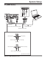
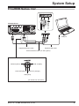
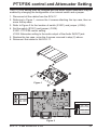
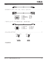
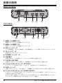
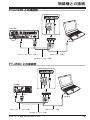
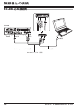
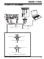
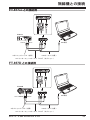
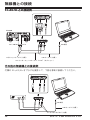
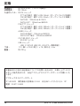
SCU-17 Instruction Manual USB INTERFACE UNIT 日本語の説明は 16 ページから記載されています。 SCU-17 USB Interface Unit 3 4 SCU-17 USB Interface Unit Introduction Introduction The SCU-17 interface unit may be used for CAT control of the transceiver with a computer via a USB connection; and for communications using SSTV, RTTY and PSK digital modes. Note:YAESU does not produce CAT, SSTV, RTTY and PSK System operating software, due to the wide variety of personal computers, operating systems, and applications in use today. The SCU-17 provides CAT communication through the USB terminal when a PC does not have an RS-232C connection. The SCU-17 is equipped with a USB audio system device, so the TX and RX audio system signals are accessible to the SCU-17 through the USB cable. Therefore, the supplied USB cable is the only connection needed between the SCU-17 and PC. The SCU-17 is equipped with a two-channel USB serial device and enables the various transmission modes and the CAT communication simultaneously. The SCU-17 operates from the USB bus power; you do not need to prepare an external power supply. For RF isolation, the SCU-17 is designed with photo relays for the PTT/FSK terminals. AF transformers are used in the AUDIO IN/OUT lines to provide excellent ground isolation. The SCU-17 is equipped with the TX and RX audio controls on the front panel, for convenient level adjustment. LED indicators on the SCU-17 front panel monitor the PTT and FSK control. The operating conditions may be quickly confirmed. SCU-17 USB Interface Unit 1 Virtual COM port driver Installation Install the virtual COM port driver on the personal computer before using the SCU-17 USB interface unit. Please see the USB Driver (Virtual COM Port Driver) on the Yaesu Website for details (http://www.yaesu.com/). Note:Do not connect the USB cable and SCU-17 to your personal computer until after the “virtual COM port driver” installation is completed, because an incorrect driver may be installed. For assistance with the software port configuration, refer to “How to Confirm the Installation, and the COM Port Number” in the “Virtual COM port Driver Installation Manual”. For information on port configuration for commercial and free computer software, refer to the manual for the software being used. When using the USB cable to supply TX and RX audio signals, set the Sound Card (input and output) settings to “USB Audio CODEC”. When using the USB cable for computer TX control, the transceiver may switch to transmit mode when the computer is started, etc. YAESU does not provide technical support for the use or operation of commercial or free computer software. 2 SCU-17 USB Interface Unit Accessories USB cable (Type “A” male to Type “B” male).................................................. 1 pc RS-232C cable (female to female, Straight Type)........................................... 1 pc ① ② ③ ④ ⑤ ① ②③④⑤ ⑥⑦ ⑧⑨ N/A SERIAL IN SERIAL OUT N/A GND ⑥ ⑦ ⑧ ⑨ N/A RTS CTS NC Connection cable (MDIN6P - MDIN6P)........................................................... 1 pc ⑥ ⑤ ④ ③ ② ① ① DATA OUT ② GND ③ DATA PTT ④ FSK OUT ⑤ DATA IN ⑥ SQL IN 3.5 mm Stereo plug ................................................................................... 2 pcs GND PTT GND IN FSK OUT PTT/FSK AUDIO Instruction manual SCU-17 USB Interface Unit 3 Controls & Connections Fr ont Panel ① ② ③ ④ ⑤ Rear Panel ⑥ ⑦ ⑧ ⑨ ⑩ ①RX audio level control knob This knob adjusts the RX audio level. ②TX audio level control knob This knob adjusts the TX audio level. ③FSK Indicator This indicator illuminates when the Mark frequency is shifted. ④TX Indicator This indicator illuminates during transmission. ⑤POWER Indicator ⑥USB Connector Connect to a computer from this jack using the supplied USB cable. ⑦CAT/RS-232C Jack This 9-pin serial DB-9 jack allows CAT communication of the transceiver. Connect a supplied RS-232C cable here and to the transceiver. ⑧3.5 mm stereo Jack (PTT/FSK) This 3-conductor, 3.5 mm stereo jack is used for PTT/FSK. For RF isolation, these terminals are designed with photo relays. ⑨DATA Jack This 6-pin (MDIN6P) jack allows DATA communication of the transceiver. ⑩3.5 mm stereo Jack (Audio IN/OUT) 4 This 3-conductor, 3.5 mm stereo jack is used for Audio IN/OUT. For RF isolation, AF transformers are used in the AUDIO IN/OUT lines. This Jack is equipped with an attenuator that is applied to the audio output. See page 13 for details about attenuation. SCU-17 USB Interface Unit System Setup FTDX1200 FTDX1200 USB port Supplied USB Cable Supplied Connection Cable Supplied RS-232C Cable FT-450D FT-450D DATA CAT USB port Supplied USB Cable Supplied Connection Cable Supplied RS-232C Cable SCU-17 USB Interface Unit 5 System Setup FT-950 FT-950 DATA CAT Supplied Connection Cable USB port Supplied USB Cable Supplied RS-232C Cable 6 SCU-17 USB Interface Unit System Setup FT-2000 Series FT-2000 Series CAT USB port Packet Interface Cable "CT-39A" (option) Supplied USB Cable Supplied RS-232C Cable SQL IN (Blue) DATA IN (Green) DATA OUT (Brown) DATA PTT (Orange) GND (Red) DATA IN (Green) DATA PTT (Orange) FSK OUT (Yellow) GND (Red) (as viewed from rear panel) SCU-17 USB Interface Unit 7 System Setup FTDX9000 Series (SSTV/PSK/RTTY) FTDX9000 Series CAT USB port Supplied RS-232C Cable Supplied USB Cable Packet Interface Cable "CT-39A" (option) SQL IN (Blue) DATA IN (Green) DATA OUT (Brown) N.C GND (Red) DATA PTT (Orange) GND (Red) DATA IN (Green) FSK OUT (Yellow) (as viewed from rear panel) 8 SCU-17 USB Interface Unit System Setup FTDX9000 Series (PSK) FTDX9000 Series CAT USB port Supplied RS-232C Cable Supplied USB Cable Packet Interface Cable "CT-39A" (option) SQL IN (Blue) DATA IN (Green) DATA OUT (Brown) DATA PTT (Orange) GND (Red) (as viewed from rear panel) SCU-17 USB Interface Unit 9 System Setup FTDX5000 Series FTDX5000 Series CAT USB port Packet Interface Cable "CT-39A" (option) Supplied USB Cable Supplied RS-232C Cable SQL IN (Blue) DATA IN (Green) DATA OUT (Brown) DATA PTT (Orange) GND (Red) DATA IN (Green) DATA PTT (Orange) FSK OUT (Yellow) GND (Red) (as viewed from rear panel) 10 SCU-17 USB Interface Unit System Setup FT-817ND/SCU-17 FT-817ND DATA USB port ACC Supplied Connection Cable Supplied USB Cable CAT Interface Cable "CT-62" (option) FT-857D/SCU-17 FT-857D CAT/LINEAR USB port DATA Supplied Connection Cable Supplied USB Cable CAT Interface Cable "CT-62" (option) SCU-17 USB Interface Unit 11 System Setup FT-897D/SCU-17 FT-897D CAT/LINEAR USB port DATA Supplied Connection Cable Supplied USB Cable CAT Interface Cable "CT-62" (option) Interfacing to other transceivers USB port Supplied USB Cable 3.5 mm Stereo plug 12 SCU-17 USB Interface Unit PTT/FSK control and Attenuator Setting The PTT/FSK setting may be changed and the audio output attenuator may be enabled by changing the configuration of an internal switch and a jumper. 1. Disconnect all the cables from the SCU-17. 2. Referring to Figure 1, remove the 4 screws attaching the top case, then remove the top case. 3. Refer to Figure 2 for the location of switch (S1001) and jumper (J1006). 4. Set the switch (S1001) and jumper (J1006). S1001: PTT/FSK control setting J1006: Attenuator setting to the audio output of the Audio IN/OUT jack. 5. Replace the top case, using the 4 screws removed in step (2) above. 6. Reconnect the cables to the SCU-17. Figure 1 S1001 PTT : RTS FSK : DTR PTT : DTR FSK : RTS J1006 ATT : OFF (100 mVrms) ATT : ON (1.4 mVrms) Figure 2 SCU-17 USB Interface Unit 13 Specifications Supply Voltage:DC 5.0 V ±5%, Negative Ground Current Consumption:130 mA Data Jack: PTT: Maximum output +25 V, 50 mA (open collector) FSK: Maximum output +25 V, 50 mA (open collector) DATA-IN: 100 mVrms @ 10 k Ohms DATA-OUT: 100 mVrms @ 600 Ohms FSK/PTT Jack:PTT: Maximum output +30 V, 250 mA (open drain) FSK: Maximum output +30 V, 250 mA (open drain) AUDIO Jack: AUDIO-IN: 100 mVrms @ 600 Ohms AUDIO-OUT: 100 mVrms @ 600 Ohms CAT/RS-232C Jack:RS-232C voltage level USB Connector: USB 1.1 or USB 2.0, USB bus power Case Size:4.37” (W) x 1.0” (H) x 2.91” (D) (111 x 25.4 x 74.0 mm) Weight (approx.):8.1 oz (230 g) 14 SCU-17 USB Interface Unit Note SCU-17 USB Interface Unit 15 特徴 / 準備 特徴 SCU-17 は、無線機の CAT 通信、 SSTV、RTTY、PSK などの各種送信制御を USB ケー ブルで接続したパソコンで行うことができるインターフェースユニットです。 RS-232C の端子がないパソコンでも USB 端子を用いて CAT 通信を行うこと ができます。 USB オーディオデバイスを搭載し、送信および受信オーディオ信号は USB ケーブルにて通信されますので、SCU-17 とパソコンの接続は、付属の USB ケーブルだけで接続可能です。 2チャンネルの USB シリアルデバイスを搭載している為、CAT 通信と同時 に各種の送信制御を行うことが可能です。 USB バスパワーにて動作しますので、外部電源は不要です。 RF インターフェア対策の為、フォトリレーを使用した PTT/FSK 端子および、 オーディオラインにトランスを使用し、GND アイソレーションされている AUDIO IN/OUT 端子を備えています。 送信および受信オーディオレベルの調整用ボリュームをフロントパネルに配 置しましたので、各レベル調整を容易に行うことができます。 PTT および、FSK コントロールのモニター用 LED インジケータをフロント パネルに配置しましたので、一目で動作状態を確認することができます。 準備 SCU-17 を使用するには、使用するパソコンに、あらかじめ仮想 COM ポートド ライバーをインストールする必要があります。 SCU-17 に仮想 COM ポートドライバーは付属していませんので、当社ホームペー ジ (http://www.yaesu.com/jp/) の「仮想 COM ポートドライバー」掲載ページよ りダウンロードしてください。 【ご注意】 ・仮想 COM ポートドライバーのインストールが完了するまでは、SCU-17 とパ ソコンとを USB ケーブルで接続しないで下さい。仮想 COM ポートドライバー をインストールしないで SCU-17 とパソコンとを接続した場合、誤ったドラ イバーがインストールされて正しく動作しなくなる恐れがあります。 ・SCU-17 を使用して無線機の通信制御を行うためのソフトのサポートは行って いません。 ・ご使用の無線機に付属装置 ( 本機 ) を接続して、SSTV、RTTY、PSK などのモー ドを運用する時は、変更申請 ( 届出 ) が必要になる場合があります。 また、技術基準適合証明設備でない設備の変更申請には、ティエスエス (TSS) 株式会社による保証認定が必要になります。 16 SCU-17 USB Interface Unit 付属品 ・USB ケーブル (A-B タイプ ).......................................... 1 ・RS-232C ケーブル ( メス - メス、ストレートタイプ ).................... 1 ① ② ③ ④ ⑤ ① ②③④⑤ ⑥⑦ ⑧⑨ N/A SERIAL IN SERIAL OUT N/A GND ⑥ ⑦ ⑧ ⑨ N/A RTS CTS NC ・コネクションケーブル (Mini-Din 6pin ー Mini-Din 6pin)..................... 1 ⑥ ⑤ ④ ③ ② ① ① DATA OUT ② GND ③ DATA PTT ④ FSK OUT ⑤ DATA IN ⑥ SQL IN ・3.5 φステレオプラグ................................................ 2 GND PTT GND IN FSK OUT PTT/FSK AUDIO ・取扱説明書 SCU-17 USB Interface Unit 17 各部の説明 フロントパネル ① ② ③ ④ ⑤ リアパネル ⑥ ⑦ ⑧ ⑨ ⑩ ①受信レベル調整ツマミ 受信オーディオレベルの調整を行うツマミです。 ②送信レベル調整ツマミ 送信オーディオレベルの調整を行うツマミです。 ③FSK インジケータ マーク周波数が、あらかじめ設定してある周波数分シフトした際に点灯するインジケータです。 ④TX インジケータ 送信時に赤く点灯するインジケータです。 ⑤POWER インジケータ ⑥USB 端子 付属の USB ケーブルを使用して、パソコンの USB 端子と接続します。 ⑦ CAT/RS-232C 端子 付属の RS-232C ケーブルを使用して、無線機の CAT/RS-232C 端子と接続します。 ⑧ 3.5-mm ステレオジャック (PTT/FSK) RF インターフェアを防ぐために、フォトリレーを使用した PTT/FSK 端子です。 ⑨ DATA ジャック 付属のコネクションケーブルを使用して、無線機の DATA 端子や PACKET 端子と接続します。 ⑩ 3.5-mm ステレオジャック (AUDIO IN/OUT) 18 RF インターフェアを防ぐために、オーディオラインにトランスを使用し、GND アイソレーショ ン可能な AUDIO IN/OUT 端子です。 なお、OUT 端子 ( 送信オーディオ出力 ) は、 SCU-17 内部のジャンパー設定を変更することにより、 アッテネーターを動作させることができます (27 ページ参照 )。 SCU-17 USB Interface Unit 無線機との接続 FTDX1200 との接続例 FTDX1200 USB 端子 USB ケーブル ( 付属 ) コネクションケーブル ( 付属 ) RS-232C ケーブル ( 付属 ) FT-450D との接続例 FT-450D DATA CAT USB 端子 コネクションケーブル ( 付属 ) USB ケーブル ( 付属 ) RS-232C ケーブル ( 付属 ) SCU-17 USB Interface Unit 19 無線機との接続 FT-950 との接続例 FT-950 DATA CAT コネクションケーブル ( 付属 ) USB 端子 USB ケーブル ( 付属 ) RS-232C ケーブル ( 付属 ) 20 SCU-17 USB Interface Unit 無線機との接続 FT-2000 シリーズとの接続例 FT-2000 シリーズ CAT USB 端子 パケットインターフェースケーブル “CT-39A”( オプション ) USB ケーブル ( 付属 ) RS-232C ケーブル ( 付属 ) SQL IN( 青 ) DATA IN( 緑 ) DATA OUT( 茶 ) DATA PTT( オレンジ ) GND( 赤 ) DATA IN( 緑 ) FSK OUT( 黄 ) DATA PTT( オレンジ ) GND( 赤 ) ※イラストは、無線機を背面から見た時の端子です。 SCU-17 USB Interface Unit 21 無線機との接続 FTDX9000 シリーズとの接続例 (SSTV/PSK/RTTY) RTTY および、SSTV (SSB モード )、 PSK (SSB モード ) で運用する場合は、下の イラストを参考に接続してください。 な お、SSB モ ー ド で 運 用 す る 場 合 は、 メ ニ ュ ー モ ー ド「No.077 SSB MIC SELECT」を「DATA」に設定してください。 FTDX9000 Series CAT USB 端子 RS-232C ケーブル ( 付属 ) USB ケーブル ( 付属 ) パケットインターフェースケーブル“CT-39A”( オプション ) SQL IN( 青 ) DATA IN( 緑 ) DATA OUT( 茶 ) N.C GND( 赤 ) DATA PTT( オレンジ ) DATA IN( 緑 ) GND( 赤 ) FSK OUT( 黄 ) ※イラストは、無線機を背面から見た時の端子です。 22 SCU-17 USB Interface Unit 無線機との接続 FTDX9000 シリーズとの接続例 (PSK) PSK を PKT モードで運用する場合は、下のイラストを参考に接続してください。 FTDX9000 Series CAT USB 端子 RS-232C ケーブル ( 付属 ) USB ケーブル ( 付属 ) パケットインターフェースケーブル “CT-39A”( オプション ) SQL IN( 青 ) DATA IN( 緑 ) DATA OUT( 茶 ) DATA PTT( オレンジ ) GND( 赤 ) ※イラストは、無線機を背面から見た時の端子です。 SCU-17 USB Interface Unit 23 無線機との接続 FTDX5000 シリーズとの接続例 FTDX5000 Series CAT USB 端子 パケットインターフェースケーブル USB ケーブル ( 付属 ) “CT-39A”( オプション ) RS-232C ケーブル ( 付属 ) SQL IN( 青 ) DATA IN( 緑 ) DATA OUT( 茶 ) DATA PTT( オレンジ ) GND( 赤 ) DATA IN( 緑 ) FSK OUT( 黄 ) DATA PTT( オレンジ ) GND( 赤 ) ※イラストは、無線機を背面から見た時の端子です。 24 SCU-17 USB Interface Unit 無線機との接続 FT-817ND との接続例 FT-817ND DATA USB 端子 ACC コネクションケーブル ( 付属 ) USB ケーブル ( 付属 ) CAT インターフェースケーブル“CT-62”( オプション ) FT-857D との接続例 FT-857D CAT/LINEAR USB 端子 DATA コネクションケーブル ( 付属 ) USB ケーブル ( 付属 ) CAT インターフェースケーブル“CT-62”( オプション ) SCU-17 USB Interface Unit 25 無線機との接続 FT-897D との接続例 FT-897D CAT/LINEAR DATA コネクションケーブル ( 付属 ) USB 端子 USB ケーブル ( 付属 ) CAT インターフェースケーブル“CT-62”( オプション ) その他の無線機との接続例 付属の 3.5 φステレオプラグを使用して、下図を参考に接続してください。 USB 端子 USB ケーブル ( 付属 ) 3.5 φステレオプラグ ( 付属 ) 26 SCU-17 USB Interface Unit 設定 SCU-17 は、内部のジャンパー設定を変更することにより、AUDIO IN/OUT 端 子の送信オーディオ出力側にアッテネーターを動作させることができます。 また、内部のスイッチを切り換えることにより、PTT/FSK の制御 (PTT 制御: RTS、FSK 制御:DTR) を変更 (PTT 制御:DTR、FSK 制御:RTS) すること ができます。 1.SCU-17 に接続されている全てのケーブル類を外します。 2.図1を参考に、4本のネジを外して上ケースを外します。 ケースが外れにくい場合は、下側のネジを緩めてください。 3.図2を参考に、ジャンパー ( J1006) の設定または、スイッチ ( S1001) の切 り換えを行います。 4.上記2で外したネジ4本で、上ケースを取り付けます。 5.上記1で外したケーブル類を接続します。 図1 S1001 PTT : RTS FSK : DTR ( 工場出荷時 ) PTT : DTR FSK : RTS J1006 アッテネーター : OFF (100 mVrms) ( 工場出荷時 ) アッテネーター : ON (1.4 mVrms) 図2 SCU-17 USB Interface Unit 27 定格 電源電圧 : DC 5.0V ± 5%、( マイナス接地 ) 消費電流 : 約 130mA 入出力レベル : DATA ジャック PTT 出力端子:最大 +25V, 50mA ( オープンコレクタ制御 ) FSK 出力端子:最大 +25V, 50mA ( オープンコレクタ制御 ) DATA-IN:100mVrms @ 10kΩ DATA-OUT:100mVrms @600Ω FSK/PTT ジャック PTT 出力端子:最大 +30V, 250mA ( オープンドレイン制御 ) FSK 出力端子:最大 +30V, 250mA ( オープンドレイン制御 ) AUDIO ジャック DATA-IN 端子:100mVrms @600Ω DATA-OUT 端子:100mVrms @600Ω CAT/RS-232C ジャック RS-232C レベル USB ジャック USB 1.1 または USB 2.0( バスパワー電源供給 ) 寸法 : 111( 幅 ) x 25.4( 高さ ) x 74( 奥行き ) mm 重量 : 約 230 g 本製品または他の当社製品についてのお問い合わせは、お買い上げいただ きました販売店または、当社アマチュアカスタマーサポートにお願いいた します。 アマチュアカスタマーサポート 〒 140-0002 東京都品川区東品川 2-5-8 天王洲パークサイドビル 11F 電話:03-6711-4045 28 SCU-17 USB Interface Unit Declaration of Conformity We, YAESU UK LTD. declare under our sole responsibility that the following equipment complies with the essential requirements of the Directive 1999/5/EC and Directive 2011/65/ EU. Type of Equipment: Brand Name: Model Number: Manufacturer: Address of Manufacturer: USB Interface Unit YAESU SCU-17 YAESU MUSEN CO., LTD. Tennozu Parkside Building, 2-5-8 Higashi-Shinagawa, Shinagawa-ku,Tokyo 140-0002 Japan Applicable Standards: This equipment is tested and conforms to the essential requirements of directive, as included in following standards. EMC Standard: RoHS2 Standard: EN 61000-6-1: 2007 EN 61000-6-3: 2007 + A1: 2011 EN 50581:2012 The technical documentation as required by the Conformity Assessment procedures is kept at the following address: Company: Address: Yaesu UK Ltd. Unit 12, Sun Valley Business Park, Winnall Close, Winchester Hampshire, SO23 0LB, U.K. Disposal of your Electronic and Electric Equipment Products with the symbol (crossed-out wheeled bin) cannot be disposed as household waste. Electronic and Electric Equipment should be recycled at a facility capable of handling these items and their waste by products. In EU countries, please contact your local equipment supplier representative or service center for information about the waste collection system in your country. This device complies with part 15 of the FCC Rules. Operation is subject to the following two conditions; (1) this device may not cause harmful interference, and (2) this device must accept any interference including interference that may cause undesired operation. SCU-17 USB Interface Unit 29 YAESU MUSEN CO., LTD. Tennozu Parkside Building 2-5-8 Higashi-Shinagawa, Shinagawa-ku, Tokyo 140-0002 Japan YAESU USA 6125 Phyllis Drive, Cypress, CA 90630, U.S.A. YAESU UK Unit 12, Sun Valley Business Park, Winnall Close Winchester, Hampshire, SO23 0LB, U.K. C 2013 八重洲無線株式会社 無断転載・複写を禁ず YAESU HK Unit 2002, 20/F, 9 Chong Yip Street, Kwun Tong, Kowloon, Hong Kong 30 EAK21X700 SCU-17 USB Interface Unit