1
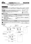
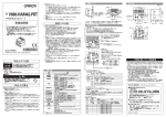
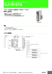
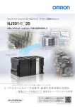
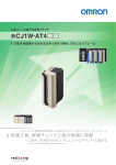
適合規格について
1.EMC規格
CS1W-V680C1
形CJ1W-V680C1
形
欧州EC指令に適合しています。
EMC規格:EN 61000-6-2
EN 61000-6-4
2.UL規格について
UL(Underwriter's Laboratories Inc.)の認証を受けています。
UL508
IDセンサユニット
取扱説明書
このたびは、
本製品をお買い上げいただきまして、
まことにありがとう
ございます。
ご使用に際しては、
次の内容をお守りください。
・ 電気の知識を有する専門家がお取り扱いください。
・ この取扱説明書をよくお読みになり、
十分にご理解のうえ、
正しく
ご使用ください。
・この取扱説明書はいつでも参照できるよう大切に保管してください。
・詳細につきましては、
ユーザーズマニュアルをご参照ください。
ERP
ERHD2
HEA
T/R /ERR
1
0C1
V68RUN
ERC
D1
HEAT/R
2
0C1
V68RUN
ERC
D1
HEAT/R
NORM
ERP
ERHD2
HEA
T/R /ERR
参照マニュアル
マニュアルNo.
SCHI-711
SDGR-703
形CJ1W-V680C1□
SCHI-709
形V680-HS52
形V680-HS63
形V680-HS65
形V680-D1KP□
SCHI-707
下記の(1)または(2)の回路に接続してご使用ください。
(1)制限電圧電流回路(UL508で認定されたもの)
・最大電圧(無負荷時):30Vrms(42.4Vピーク)以下
および
・最大電流:①8A以下(短絡時を含む)または
②下表の定格を持つ回路保護器(ヒューズ等)で制限されて
いる場合
無負荷電圧(Vピーク)
0∼20
最大電流定格(A)
5.0
100
20を超え30まで
ピーク電圧値
(2)UL1310に従うクラス2電源ユニットまたはUL1585に従うクラス2トラン
スを電源とする最大電圧30Vrms(42.4Vピーク)以下の回路 (クラス2回路)
(3)定格周囲温度は、55℃である。
SCHI-703
SBCA-301
SBCA-349
SBCA-350
SCBA-312
SCBA-313
SBCA-351
NORM
/ERR
/ERR
NORM
NORM
TES
T
TES
T
ON
ON
HEA
D
HEA
HEA
D1
安全上の要点
D2
4V
DC2UT
INP
+
-
* 1 6 6 0 8 0 9 - 7 I *
© OMRON Corporation 2007 All Rights Reserved.
安全上のご注意
●警告表示の意味
警告
正しい取扱いをしなければ、
この危険のために、
軽傷・中程度の傷害
を負ったり、
万一の場合には重傷や死亡にいたる恐れがあります。
ま
た、
同様に重大な物的損害をもたらす恐れがあります。
注意
正しい取扱いをしなければ、
この危険のために、
時に軽傷・中程度の
傷害を負ったり、
あるいは物的損害を受ける恐れがあります。
●警告表示
警告
通電中は、分解しないでください。
感電の恐れがあります。
通電中は、端子に触れないでください。
感電の恐れがあります。
プログラマブルコントローラ(CPUユニットおよび各ユニットを含む、以下
PLCといいます)の故障や外部要因による異常が発生した場合も、
シス
テム全体が安全側に働くように、PLCの外部で安全策を施してください。
異常動作により、重大な事故につながる恐れがあります。
(1)非常停止回路、
インターロック回路、
リミット回路など、安全保護に関
する回路は、必ずPLC外部の制御回路で構成してください。
(2)PLCは自己診断機能で異常を検出したときや、運転停止故障診断
(FALS)命令を実行したとき、運転を停止して全出力をOFFします。
(3)出力リレーの溶着や焼損、出力トランジスタの破壊などによって、
PLCの出力がONまたはOFFになったままになることがあります。
このとき、
システムが安全側に動作するよう、PLC外部で対策を施し
てください。
注意
サイクルタイムが延びても影響がないことを確認してから、
オンライン
エディットしてください。入力信号を読取れないことがあります。
1. 信号の断線、
瞬時停電による異常信号などに備えて、
ご使用者側でフェールセーフ対
策を施してください。
2. ユーザーズマニュアルで指定した電源電圧で使用してください。
3. 電源事情が悪い場所では特に、
定格の電圧や周波数の電源が供給できるようにして
ご使用ください。
4. 外部配線の短絡に備えて、
ブレーカーなどの安全策を施してください。
5. 入力部は、
定格入力電圧を超える電圧を印加しないでください。
6. 出力部は、
最大開閉能力を超える電圧の印加および負荷の接続をしないでください。
7. 次のことを行うときは、
PLC本体の電源をOFFにしてください。
・電源ユニッ
ト、
I/Oユニッ
トなどの各種ユニッ
トやCPUユニッ
ト、
メモリカセッ
トの着脱
・装置の組み立て
・ディ
ップスイッチやロータリスイッチの設定
・ケーブルの接続、
配線
8. 形CS1W-V680C1□:PLCのベース取り付けねじ、
端子台のねじ、
ケーブルのねじは、
本
書およびユーザーズマニュアルで指定した規定トルクで締めてください。
取付け時のねじ締めトルクは、
0.4N・mで確実に固定してください。
9. 複数のアンテナを隣接設置される場合、
相互干渉により交信性能が低下する恐れがあ
りますので、
「タグ・アンプユーザーズマニュアル(EEPROMタイプ)(カタログ番号:
SCHI-709)」、
「タグ・アンプユーザーズマニュアル(FRAMタイプ)(カタログ番号:
SCHI-707)」を参照し、
アンテナ間の相互干渉がないことを確認して設置してください。
10. 本書およびユーザーズマニュアルで示すとおり正しく配線してください。
11. 本製品を分解して修理や改造をしないでください。
12. 運転開始の前にディ
ップスイッチ、
データメモリ(DM)が正しく設定されていることを確認し
てください。
13. ユニッ
ト内に配線クズや切粉などが入らないようにしてください。
焼損、
故障、
誤動作の
原因となります。
特に施工時は覆いを付けるなどの対策を行ってください。
14. ユニッ
ト開口部から異物を入れないでください。
焼損、
感電、
故障の可能性があります。
15. 出荷時からユニッ
ト上部に防塵ラベルが貼ってある場合は、
通電前に必ずラベルを外し
てください。
放熱できず、
誤動作の可能性があります。
16. ケーブルやコードを無理に引っ張ったり曲げたりしないでください。
17. ケーブルやコードの上にものを載せないでください。
18. 端子台を十分に確認してから装着してください。
19. 端子台、
メモリユニッ
ト、
増設ケーブルなどロック機構のあるものは必ずロックしていること
を確認してからご使用ください。
20. 作成したユーザプログラムは、
十分な動作確認を行った後、
本運転に移行してください。
21. 配線を十分に確認してから通電してください。
22. 次のことを行うときは、
設備に影響がないことを確認してください。
・PLC動作モードの変更
・接点の強制セッ
ト/リセッ
ト
・設定値、
現在値の変更
23. 接地された金属に触るなどして人体の静電気を放電させてから、
ユニッ
トに触れてください。
24. 形CS1W-V680C12は、
外部よりDC24Vを入力する必要がありますが、
ご使用される電
源は強化絶縁(2重絶縁)
された電源をお使いください。
25. 形CS1W-V680C12をご使用になる場合、
外部入力のDC電源は、
定格の電源電圧
(DC24V +10% -15%)内であることを確認してご使用ください。
26. 電源の逆接続はしないでください。
27. ケースの隙間から水や針金を入れないでください。
火災や感電の原因となります。
28. 万一、
製品に異常を感じたときには、
すぐに使用を中止し、
電源を切った上で、
当社支店
・営業所までご相談ください。
29. 本製品を廃棄する際は、
産業廃棄物として処理してください。
30. 清掃時、
シンナー、
ベンゼン、
アセトン、
灯油はご使用しないでください。
形式
形CS1W-V680C1□
形CJ1W-V680C1□
SBCA-346
SBCA-347
SBCA-337
SBCA-303
SBCA-358
SBCA-359
SBCA-360
SBCA-362
形V680-HS52
形V680-HS63
形V680-HS65
形V680-D□□KF□
形V680-H01
形V680-D1KP58HT
形CS1□-CPU □□H
形CS1□-CPU □□-V1
形CJ2□-CPU □□
形CJ2□-CPU □□-EIP
形CJ1H-CPU □□-H-R
形CJ1□-CPU □□-EIP
形CS1□-CPU □□□
形CS1□-CPU □□-V1
形CJ1□-CPU □□□
形CJ1□-CPU □□H-R
形CJ1□-CPU □□
形CS1□-CPU □□□
形CS1□-CPU □□-V1
形CJ2□-CPU □□
形CJ2□-CPU □□-EIP
形CJ1□-CPU □□□
形CJ1□-CPU □□H-R
形CJ1□-CPU □□
形CXONE-AL□□C/D-V□
形WS02-CXPC□-V□
形CQM1H-PRO01
形CQM1-PRO01
形C200H-PRO27
形NJ□□□-□□□□
形NJ-P□3001
形NJ□□□-□□□□
形SYSMAC-SE2□□□
マニュアル名称
SYSMAC CJ/CSシリーズ
ID センサユニッ
ト ユーザーズマニュアル
CJシリーズ IDセンサユニッ
ト
ユーザーズマニュアル NJ接続編
記載内容
SYSMAC CJ/CSシリーズのIDセンサユニッ
トの使用方法について記載して
います。
CJシリーズ IDセンサユニッ
トをNJシリーズCPUユニッ
トで使用するために
必要な情報について記載しています。
RFIDシステム形V680シリーズ
タグ・アンプ ユーザーズマニュアル(EEPROM)
RFIDシステム形V680シリーズのアンテナおよびEEPROMタイプタグの
使用方法について記載しています。
RFIDシステム形V680シリーズ
タグ・アンプ ユーザーズマニュアル(FRAM)
RFIDシステム形V680シリーズのアンテナおよびFRAMタイプタグの
使用方法について記載しています。
耐熱用途RFIDシステム
形V680シリーズ ユーザーズマニュアル
SYSMAC CSシリーズ
ユーザーズマニュアル セッ
トアップ編
SYSMAC CJシリーズ CJ2 CPUユニッ
ト
ユーザーズマニュアル ハードウェア編
SYSMAC CJシリーズ CJ2 CPUユニッ
ト
ユーザーズマニュアル ソフトウェア編
SYSMAC CJシリーズ
ユーザーズマニュアル セッ
トアップ編
耐熱用途RFIDシステムのアンテナ形V680-H01および、
タグ形V680-D1KP58HTの使用方法について記載しています。
SYSMAC CSシリーズの概要、
仕様、
設置、
保守などの方法に関して記載
しています。
SYSMAC CJシリーズ CJ2 CPUユニッ
トの概要、
仕様、
設置、
保守などの
方法に関して記載しています。
SYSMAC CJシリーズ CJ2 CPUユニッ
トの機能の使い方について記載して
います。
SYSMAC CJシリーズの概要、
仕様、
設置、
保守などの方法について記載して
います。
SYSMAC CS/CJシリーズ
ユーザーズマニュアル プログラミング編
SYSMAC CS/CJシリーズの機能の使い方について記載しています。
SYSMAC CS/CJシリーズ
コマンドリファレンス
SYSMAC CS/CJシリーズの命令語の使い方について記載しています。
FA統合ツールパッケージ CX-One セッ
トアップマニュアル
CX-Integrator オペレーションマニュアル
CX-Programmer オペレーションマニュアル
プログラミングツールCX-Programmerの操作方法について説明しています。
FA統合ツールパッケージCX-Oneのセッ
トアップ方法、
操作方法について
説明しています。
プログラミングコンソール オペレーションマニュアル
SYSMAC CS/CJシリーズのプログラミングコンソールの操作方法について
記載しています。
NJシリーズ CPUユニッ
ト ユーザーズマニュアル ハードウェア編 NJシリーズ CPUユニッ
トの概要、
仕様、
設置、
保守などの方法に関して
記載しています。
NJシリーズ CPUユニッ
ト ユーザーズマニュアル ソフトウェア編 NJシリーズ CPUユニッ
トの機能の使い方について記載しています。
NJシリーズ コマンドリファレンス編
NJシリーズの基本的な命令語の使い方について記載しています。
Sysmac Studio Version 1 オペレーションマニュアル
プログラミングツールSysmac Studioの操作方法について説明しています。
使用上の注意
1. 本書およびユーザーズマニュアルに示す通り、
正しく設置してください。
2. 次のような場所では使用および保管しないでください。
・日光が直接あたる場所
・周囲温度や相対湿度が仕様値の範囲を超える場所
・温度の変化が急激で結露するような場所
・腐食性ガス、
可燃性のガスのある場所
・ちり、
ほこり、
塩分、
鉄粉が多い場所
・水、
油、
薬品などの飛沫がかかる場所
・本体に直接振動や衝撃が伝わる場所
3. 次のような場所で使用する際は、
遮蔽対策を十分に行ってください。
・静電気などによるノイズが発生する場所
・強い電解や磁界が生じる場所
・放射能を被曝する恐れのある場所
・電源線が近くを通る場所
● CS1W-V680C1□
ご承諾事項
当社商品は、一般工業製品向けの汎用品として設計製造されています。従いまして、次に
掲げる用途での使用を意図しておらず、
お客様が当社商品をこれらの用途に使用される際
には、当社は当社商品に対して一切保証をいたしません。
ただし、次に掲げる用途であって
も当社の意図した特別な商品用途の場合や特別の合意がある場合は除きます。
(a) 高い安全性が必要とされる用途
(例:原子力制御設備、燃焼設備、航空・宇宙設備、鉄
道設備、昇降設備、娯楽設備、医用機器、安全装置、
その他生命・身体に危険が及び
うる用途)
(b) 高い信頼性が必要な用途
(例:ガス・水道・電気等の供給システム、24時間連続運転
システム、決済システムほか権利・財産を取扱う用途など)
(c) 厳しい条件または環境での用途
(例:屋外に設置する設備、化学的汚染を被る設備、
電磁的妨害を被る設備、振動・衝撃を受ける設備など)
(d) カタログ等に記載のない条件や環境での用途
取り付け方法
(1)ユニット裏面上部の固定用ツメをベースユニットに引っかけ、コネク
タが正しく嵌合するように押し付けます。
(2)ユニット下部のねじを+ドライバで締めます。
締め付けは3.5in.lb. (0.4N・m)のトルクで行ってください。
インダストリアルオートメーションビジネスカンパニー 固定用ツメ
●製品に関するお問い合わせ先
お客様相談室
ベースユニット
固定ネジ
(3)外部電源供給の配線について(CS1W-V680C12のみ)
AWG18∼26を使用し、締め付けは5.1in.lb. (0.58N・m)のトルクで行って
ください。
(1)CJシリーズの各ユニットのコネクタをかみ合わせ、ユニット上部およ
びユニット下部のスライダーで各ユニットをロックします。
A
(2)DINレールにA部を引っかけ、B方向に押して装着します。
コネクタ
0120-919-066
フック用穴
ロック
055-982-5015(通話料がかかります)
●FAXやWebページでもお問い合わせいただけます。
055-982-5051 / www.fa.omron.co.jp
●その他のお問い合わせ
解除
B
● 接続可能アンテナ・アンプ
オムロン
■営業時間:8:00∼21:00 ■営業日:365日
FAX
スライダ
クイック
携帯電話・PHS・IP電話などではご利用いただけませんので、
下記の電話番号へおかけください。
電話
● CJ1W-V680C1□
フック
*(a)から(d)に記載されている他、本カタログ等記載の商品は自動車
(二輪車含む。以下同
じ)
向けではありません。自動車に搭載する用途には利用しないで下さい。自動車搭載
用商品については当社営業担当者にご相談ください。
*上記は適合用途の条件の一部です。当社のベスト、総合カタログ、データシート等最新版
のカタログ、
マニュアルに記載の保証・免責事項の内容をよく読んでご使用ください。
アンテナユニット : V680-H01-V2(C□1W-V680C11のみ接続可)
アンプ ユニット : V680-HA63A、V680-HA63B
納期・価格・サンプル・仕様書は貴社のお取引先、または貴社
担当オムロン販売員にご相談ください。
オムロン制御機器販売店やオムロン販売拠点は、Webページで
ご案内しています。
A v 2 0 1 4 年7月
Applicable Standards
CS1W-V680C1
Model CJ1W-V680C1
Model
ID Sensor Units
INSTRUCTION SHEET
NOTICE:
This product meets CISPR11 class A. The intended use of
this product is in an industrial environment only.
TRACEABILITY INFORMATION:
Importer in EU :
Omron Europe B.V.
Wegalaan 67-69
2132 JD Hoofddorp,
The Netherlands
Manufacturer:
Omron Corporation,
Shiokoji Horikawa, Shimogyo-ku,
Kyoto 600-8530 JAPAN
1. EMC Standards
The product has conformed to the European EMC directive.
Harmonized standards : EN 61000-6-2 and EN 61000-6-4
2.UL Standards
The product has been certified by UL (Underwriters Laboratories Inc.).
UL508
Use the product connected to one of the following two circuits.
(1) Limited Voltage/Current Circuit (Approved in UL508)
A circuit that uses as its power supply the secondary coil of an insulated
transformer that satisfies the following conditions:
・Maximum voltage (with no-load):30 Vrms (42.4 V peak) OR
・Maximun current: (1) 8A (including when shorted) OR
(2) A current restricted by a circuit protective device (e.g.,
fuse) with the following ratings
No-load voltage (V peak)
Maximum current rating (A)
0 to 20
5.0
100
Over 20 to 30
Peak voltage
(2) A circuit with a maximum voltage of 30 Vrms (42.4 V peak) that uses as its
power supply a Class 2 power supply defined in UL1310 or a Class 2
transformer defined in UL1585.
(3) Environmental - Rated 55℃ surrounding air.
Precautions for Safe Use
Notice:
This is a class A product. In residential areas it may cause radio
interference, in which case the user may be required to take adequate
measures to reduce interference.
© OMRON Corporation 2007 All Rights Reserved.
Sefety Precautions
●Definition of Precautionary Information
Indicates a potentially hazardous situation which, if not
avoided, will result in minor or moderate injury, or may
WARNING result in serious injury or death. Additionally there may
CAUTION
be significant property damage.
Indicates a potentially hazardous situation which,
if not avoided, may result in minor or moderate
injury or in property damage.
●Warning
WARNING
Never attempt to disassemble any Units while power is being
supplied. Doing so may result in serious electrical shock or
electrocution.
Never touch any of the terminals while power is being supplied.
Doing so may result in serious electrical shock or electrocution.
Provide safety measures in external circuits, l.e., not in the PLC (CPU
Unit including associated Units), in order to ensure safety in the
system if an abnormality occurs due to malfunction of the PLC or
another external factor affecting the PLC operation. Not doing so may
result in serious accidents.
・Emergency stop circuits, interlock circuits, limit circuits, and similar
safety measures must be provided in external control circuits.
・The PLC will turn OFF all outputs when its self-diagnosis function
detects any error or when a severe failure alarm (FALS) instruction is
executed. As a countermeasure for such errors, external safety
measures must be provided to ensure safety in the system.
・The PLC outputs may remain ON or OFF due to deposition or burning
of the output relays or destruction of the output transistors, As a
countermeasure for such problems, external safety measures must be
provided to ensure safety in the system.
This product is not designed for use in directly or indirectly
detecting human bodies in safety-related applications. Do not
use the product as a sensing device for human protection.
CAUTION
Execute online edit only after confirming that no adverse effects
will be caused by extending the cycle time. Otherwise, the input
signals may not be readable.
1. Fail-safe measures must be taken by the customer to ensure safety in the event that outputs from
Output Units remain ON as a result of internal circuit failures, which can occur in relays,
transistors, and other elements.
2. Always use the power supply voltages specified in the operation manuals. An incorrect
voltage may result in malfunction or burning.
3. Take appropriate measures to ensure that the specified power with the rated voltage and
frequency is supplied in places where the power supply is unstable. An incorrect power supply
may result in malfuncion.
4. Install external breakers and take other safety measures against short-circuting in external
wiring. Insufficient safety measures against short-circuiting may result in burning.
5. Do not apply voltages to the Input Units in excess of the rated input voltage. Excess Voltages
may result in burning.
6. Do not apply voltages or connect loads to the Output Units in excess of the maximun
switching capacity. Excess voltage or loads may result in burning.
7. Always turn OFF the power supply to the PLC before attempting any of the following.
Performing any of the following with the power supply turned ON may lead to electrical
shock:
・Mounting or removing any Units (e.g. Power Supply Unit, I/O Units, CPU Unit, etc.) or
Memory Cassettes.
・Assembling any devices or racks.
・Setting DIP switches or rotary switches.
・Connectiong or disconnecting any cables or wiring.
8. Be sure that all the mounting screws, terminal screws, and cable connector screws are
tightened to the torque specified in the relevant manuals. Incorrect tightening torque may
result in malfunction.
Tighten screws to 0.4 N・m when mounting the product.
9. If multiple Antennas are mounted near each other, communications performance may
decrease due to mutual interference. Refer to Installing Antennas in the V680 Series User's
Manual for Amplifiers, Antennas, and ID Tags (Cat. No. Z262 , Z248) and check to make
sure there is no mutual interference.
10. Install the Units properly as specified in the operetion manuals. Improper installation of the
Units may result in malfunction.
11. Do not attempt to take any Units apart, to repair any Units, or to modify any Units in any way.
12. Check switch settings, the contents of the DM Area, and other preparations before starting
operation. Starting operation without the proper settings or data may result in an unexpected
operation.
13. Do not allow wire clippings, shavings, or other foreign material to enter any Unit. Otherwise,
Unit burning, failure, or malfunction may occur. Cover the Units or take other suitable
countermeasures, especially during wiring work.
14. Do not allow foreign matter to enter the openings in the Unit. Doing so may result in Unit
burning, electric shock, or failure.
15. Always remove any dustproof labels that are on the top of the Units when they are shipped
before you turn on the power supply. If the labels are not removed, heat will accumulate and
malfunctions may occur.
16. Observe the following precautions when wiring cables.
・Do not bend the cables past their natural bending radius.
・Do not pull on the cables.
17. Do not place heavy objects on top of the cables.
18. Check terminal blocks sufficiently before mounting them.
19. Be sure that the terminal blocks, Memory Units, expansion cables, and other items with
locking devices are properly locked into place, Improper locking may result in malfuntion.
20. Check the user program for proper execution before actually running it on the Unit. Not
checking the program may result in an unexpected operation.
21. Check all wiring carefully before turning ON the power supply.
22. Confirm that no adverse effect will occur in the system before attempting any of the
following. Not doing so may result in an unexpected operation.
・Changing the operating mode of the PLC.
・Force-setting / force-resetting any bit in memory.
・Changing the present value of any word or any set value in memory.
23. Before touching a Unit, be sure to first touch a grounded metallic object in order to discharge
any static build-up. Not doing so may result in malfuncion or damage.
24. Confirm the power supply is Reinforced Insulation(Double Insulation) for the CS1W-V680C12.
25. Confirm that the CS1W-V680C12 is within the rated power supply voltage (24 VDC
+10%/-15%) before using it.
26. Do not reverse polarity when connecting the power supply.
27. Do not allow water to enter or insert wire in the gaps of the case. Fire or electric shock may
result.
28. If you suspect that anything is wrong with the product at any time, stop using it immediately,
turn OFF the power supply, and consult with your OMRON representative.
29. When disposing of the product, dispose of it as industrial waste.
30. Do not use thinners, benzenes, acetones and kerosenes for cleaning.
■ Reference Manuals
Cat No.
Z271
Z317
Z262
Z248
Z221
W339
W472
W473
W393
W394
W474
Precautions for Correct Use
1. Do not install and storage the product in the follwing locations.
・Where the PLC is exposed to direct sunlight.
・Where the ambient temperature or humidity is outside the ranges given in the Unit
specifications.
・Where the PLC may be affected by condensation due to radical temperature changes.
・Where there is any corrosive or inflammable gas.
・Where there is excessive dust, saline air, or metal powder.
・Where the PLC is affected by vibration or shock.
・Where any water, oil or chemical may splash on the PLC.
2. Provide proper shielding when installing in the following locations:
・Locations subject to static electricity or other sources of noise.
・Locations subject to strong electromagnetic fields.
・Locations subject to possible exposure to radiation.
・Locations near to power supply lines.
W463
W464
W446
W341
W500
W501
W502
W504
Name
SYSMAC CS/CJ Series CS1W-V680C1□/CJ1W-V680C1□
V680 Series ID Sensor Units User’s Manual
CJ series CJ1W-V680C1□
ID Sensor Units Operation Manual for NJ-series CPU Unit
RFID System V680 Series User’s Manual
for Amplifiers, Antennas, and ID Tags (EEPROM)
RFID System V680 Series User’s Manual
for Amplifiers, Antennas, and ID Tags (FRAM)
Heat-resistive RFID System V680 Series User’s Manual
SYSMAC CS Series CS1G/H-CPU□□H, CS1G/HCPU□□-EV1
Programmable Controllers Operation Manual
SYSMAC CJ Series CJ2H-CPU6□-EIP, CJ2H-CPU6□, CJ2M-CPU□□
CJ2 CPU Unit Hardware user’
s Manual
SYSMAC CJ Series CJ2H-CPU6□-EIP, CJ2H-CPU6□, CJ2M-CPU□□
CJ2 CPU Unit Software Manual
SYSMAC CJ Series CJ1H-CPU□□H-R, CJ1G/H-CPU□□H,
CJ1G-CPU□□P, CJ1G-CPU□□, CJ1M-CPU□□
Programmable Controllers Operation Manual
SYSMAC CS Series CS1G/H-CPU□□-EV1, CS1G/H-CPU□□H,
CS1D-CPU□□H, CS1D-CPU□□S
SYSMAC CJ-Series CJ1H-CPU□□H-R, CJ1G-CPU□□,
CJ1G/H-CPU□□H, CJ1G-CPU□□P, CJ1M-CPU□□
Programmable Controllers Programming Manual
SYSMAC CS Series CS1□-CPU□□□-□□
SYSMAC CJ-Series CJ2H-CPU6□-EV1, CJ2H-CPU6□, CJ2M-CPU□□,
CJ1□-CPU□□□-□
Programmable Controllers Instructions Reference Manual
CXONE-AL□□C-V4/AL□□D-V4, CXONE-LT□□C-V4
SYSMAC CX-One FA Integrated Tool Package Setup Manual
CXONE-AL□□C-V4/AL□□D-V4
SYSMAC CS/CJ/CP/NSJ/NJ Series CX-Integrator Operation Manual
WS02-CXP-C□-V□
SYSMAC CX-Programmer Operation Manual
SYSMAC CS/CJ Series CQM1H-PR001-E/CQM1-PR001-E/C200H-PR027-E
Programming Consoles Operation Manual
NJ□□□-□□□□, NJ-P□3001
NJ-series CPU Unit Hardware User’s Manual
NJ□□□-□□□□
NJ-series CPU Unit Software User’s Manual
NJ□□□-□□□□
NJ-series Instructions Reference Manual
SYSMAC-SE2□□□□
Sysmac Studio Version 1 Operation Manual
3. The operating environment of the PLC System can have a large effect on the longevity and
raliability of the system. Improper operating environments can lead to malfunction, failure,
and other unforeseeable problems with the PLC System. Be sure that the operating
environment is within the specified conditions at installation and remains within the specified
conditions during the life of the system.
Mounting method
・CS1W-V680C1□
(1) Hook the fixing claw at the top of the back side of the Unit onto the base unit and push it so
that the connector is fit in correctly.
(2) Tighten the screws at the bottom of the Unit with a Phillips type screwdriver.
Tighten them to torque of 3.5in.lb. (0.4N・m).
Hook
Backplane
Mounting screw
(3) Wiring external power supply (CS1W-V680C12 only)
Use the AWG18 to 26 wire and tighten to torque of 5.1in.lb. (0.58N・m).
・CJ1W-V680C1□
(1) Align the connectors and press in firmly on the Units to connect them completely.
Move the yellow sliders on the top and bottom of the Unit to the lock position to secure the
Units. The sliders should click into place.
(2) When mounting the Units to DIN Rail, hook the Units at point A and then press in direction B.
A
Hooks
Connector
Slider
Hook holes
Locked
Released
B
・Connectable Antenna and Amplifier
Antenna unit : V680-H01-V2 (connecting to C□1W-V680C11 only)
Amplifier unit : V680-HA63A and V680-HA63B
・Notice for Korea Radio Law
A급 기기(업무용 방송통신기자재)
이 기기는 업무용(A급) 전자파적합기기로서 판매자
또는 사용자는 이 점을 주의하시기 바라며,가정외의
지역에서 사용하는 것을 목적으로 합니다.
Suitability for Use
Omron Companies shall not be responsible for conformity with any standards,
codes or regulations which apply to the combination of the Product in the
Buyer’s application or use of the Product. At Buyer’s request, Omron will
provide applicable third party certification documents identifying ratings and
limitations of use which apply to the Product. This information by itself is not
sufficient for a complete determination of the suitability of the Product in
combination with the end product, machine, system, or other application or
use. Buyer shall be solely responsible for determining appropriateness of the
particular Product with respect to Buyer’s application, product or system.
Buyer shall take application responsibility in all cases.
NEVER USE THE PRODUCT FOR AN APPLICATION INVOLVING
SERIOUS RISK TO LIFE OR PROPERTY WITHOUT ENSURING THAT THE
SYSTEM AS A WHOLE HAS BEEN DESIGNED TO ADDRESS THE RISKS,
AND THAT THE OMRON PRODUCT(S) IS PROPERLY RATED AND
INSTALLED FOR THE INTENDED USE WITHIN THE OVERALL
EQUIPMENT OR SYSTEM.
See also Product catalog for Warranty and Limitation of Liability.
OMRON Corporation
Tokyo, JAPAN
Industrial Automation Company
Contact: www.ia.omron.com
Regional Headquarters
OMRON EUROPE B.V.
Sensor Business Unit
Carl-Benz-Str. 4, D-71154 Nufringen, Germany
Tel: (49) 7032-811-0/Fax: (49) 7032-811-199
OMRON ELECTRONICS LLC
2895 Greenspoint Parkway, Suite 200
Hoffman Estates, IL 60169 U.S.A.
Tel: (1) 847-843-7900/Fax: (1) 847-843-7787
OMRON ASIA PACIFIC PTE. LTD.
No. 438A Alexandra Road # 05-05/08 (Lobby 2),
Alexandra Technopark,
Singapore 119967
Tel: (65) 6835-3011/Fax: (65) 6835-2711
OMRON (CHINA) CO., LTD.
Room 2211, Bank of China Tower,
200 Yin Cheng Zhong Road,
PuDong New Area, Shanghai, 200120, China
Tel: (86) 21-5037-2222/Fax: (86) 21-5037-2200
D s O c t , 2014