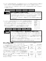
1
スイングロックチャック SWING LOCK CHUCK H063M H064M 取扱説明書 INSTRUCTION MANUAL 重要 IMPORTANT 本取扱説明書をよく読み,内容を十分理解した 上でこの製品を使用してください。 この取扱説明書は大切に保管し,製品の所有者 が変わった場合,この説明書も新しい所有者に 手渡してください。 Be sure to read and understand this instruction manual thoroughly before operating this product. Please save this manual. When ownership of this product is transferred, submit this manual to the new owner. 豊和工業株式会社 HOWA MACHINERY, LTD. 目 次 はじめに 安全についてのインフォメーション 安全のために 1. 構造と作動・・・・・・・・・・・・・・・・・・・・・ 1.1 形番表示・・・・・・・・・・・・・・・・・・・ 1.2 構造と作動・・・・・・・・・・・・・・・・・・ 2.取付け方法・・・・・・・・・・・・・・・・・・・・・ 2.1 開梱・・・・・・・・・・・・・・・・・・・・・ 2.2 付属品・・・・・・・・・・・・・・・・・・・・ 2.3 準備するもの・・・・・・・・・・・・・・・・・ 2.4 ストローク規制・・・・・・・・・・・・・・・・ 2.5 内径把握への組替え・・・・・・・・・・・・・・ 2.6 取付作業・・・・・・・・・・・・・・・・・・・ 2.6.1 作業を始める前に ・・・・・・・・・・・ 2.6.2 チャックアダプタの取付け ・・・・・・・ 2.6.3 チャックの取付け ・・・・・・・・・・・ 2.6.4 点検・・・・・・・・・・・・・・・・・・ 2.6.5 バランス・・・・・・・・・・・・・・・・ 3.使用上の注意・・・・・・・・・・・・・・・・・・・・ 3.1 トップジョーの選定・・・・・・・・・・・・・・ 3.2 イコライズ機能の規制・・・・・・・・・・・・・ 3.3 トップジョーの取付け・・・・・・・・・・・・・ 3.4 トップジョーの成形・・・・・・・・・・・・・・ 3.5 グリッパ付トップジョーの設計・・・・・・・・・ 3.6 ストッパの取付け・・・・・・・・・・・・・・・ 3.7 使用条件の設定・・・・・・・・・・・・・・・・ 3.7.1 許容シリンダ力・・・・・・・・・・・・・ 3.7.2 ワークの変形・・・・・・・・・・・・・・ 3.8 作業上の注意・・・・・・・・・・・・・・・・・ 3.8.1 ワークを把握する前に ・・・・・・・・・ 3.8.2 ワークを把握するとき ・・・・・・・・・ 3.8.3 切削中 ・・・・・・・・・・・・・・・・ 3.8.4 作業終了・・・・・・・・・・・・・・・・ 4.保守・・・・・・・・・・・・・・・・・・・・・・・・ 4.1 給油・・・・・・・・・・・・・・・・・・・・・ 4.2 分解と清掃・・・・・・・・・・・・・・・・・・ 4.2.1 分解手順・・・・・・・・・・・・・・・・ 4.2.2 組立手順・・・・・・・・・・・・・・・・ 4.3 安全回転数の設定・・・・・・・・・・・・・・・ 4.4 パーツリスト・・・・・・・・・・・・・・・・・ 5.故障対策・・・・・・・・・・・・・・・・・・・・・・ 6.仕様・・・・・・・・・・・・・・・・・・・・・・・・ 6.1 仕様・・・・・・・・・・・・・・・・・・・・・ 6.2 寸法・・・・・・・・・・・・・・・・・・・・・ 6.3 把握力・・・・・・・・・・・・・・・・・・・・ 6.4 標準生爪・・・・・・・・・・・・・・・・・・・ 6.5 チャックボデー許容加工範囲・・・・・・・・・・ 6.6 付属品・・・・・・・・・・・・・・・・・・・・ 限定保証・・・・・・・・・・・・・・・・・・・・・・・ 4 4 4 5 5 5 5 5 5 6 6 6 6 8 8 9 9 9 9 10 12 13 14 14 14 15 15 16 16 17 17 17 18 18 18 20 21 22 23 23 24 26 26 27 28 28 はじめに 1.この取扱説明書は,H063M・H064M形スイングロックチャックの標準形について説明しています。 2.このチャックをご使用いただく前に,必ずこの取扱説明書を熟読し,取付け・運転・点検・保守について十分 に理解した上でご使用くださるようお願いします。 3.この取扱説明書の記載事項を守らない場合,作業者や周りの人を巻き込んだ重大な事故や機械の破損に結びつ く事があります。 4.この取扱説明書は常に手元に置き,紛失しないように大切に保管してください。 5.この取扱説明書と,この取扱説明書が対象とする製品についての問い合わせは下記へお願いします。 またこの取扱説明書を紛失したときも下記へ直接請求してください。 豊和工業株式会社 機械事業部 産業機器グループ 産業機器グループ 〒452-8601 愛知県清須市須ケ口 1900 番地 1 TEL (052) 408-1254 FAX (052) 409-3766 6.この取扱説明書はSI単位で書かれています。 従来単位による数値は以下の式で求めることができます。 圧力 1MPa=10.197kgf/cm2 力 1kN =101.97kgf トルク 1N・m=0.10197kgf・m 安全についてのインフォメーション この製品を安全にご使用していただくために必要な警告事項を,安全警告シンボルと共に記載してあります。警告 事項を良く読み,十分に理解してください。 この取扱説明書の警告メッセージをより良く理解していただくために,警告シンボルを次のように使い分けてあり ます。 危険 警告 注意 この表示 この表示は 表示は,取扱いを 取扱いを誤 いを誤った場合 った場合に 場合に,重傷もしくは 重傷もしくは死 もしくは死に至る危険が 危険が切迫して 切迫して生 して生じることが 想定される 想定される事項 される事項を 事項を示します。 します。 これらの警告 これらの警告メッセージ 警告メッセージには メッセージには, には,危険を 危険を回避するのに 回避するのに講 するのに講じなければならない予防措置 じなければならない予防措置が 予防措置が含ま れます。 この表示 この表示は 表示は,取扱いを 取扱いを誤 いを誤った場合 った場合に 場合に,重傷もしくは 重傷もしくは死 もしくは死に至る可能性が 可能性が想定される 想定される事項 される事項を 事項を示 します。 。 します これらの警告 これらの警告メッセージ 警告メッセージには メッセージには, には,危険を 危険を回避するのに 回避するのに講 するのに講じなければならない予防措置 じなければならない予防措置が 予防措置が含ま れます。 この表示 この表示は 表示は,取扱いを 取扱いを誤 いを誤った場合 った場合に 場合に,軽微な 軽微なケガの ケガの発生または 発生または機械 または機械の 機械の損傷が 損傷が想定される 想定される状 される状 態を示します。 します。 当社は,あらゆる環境下における運転・操作・点検・保守のすべての危険を予測することはできません。そのため, この取扱説明書に明記されている警告は,安全のすべてを網羅したものではありません。 また,「できないこと」や「してはいけないこと」は極めて多くあり,この取扱説明書にすべて書く事はできませ ん。この取扱説明書に「できる」と書いてない限り,「できない」と考えてください。もし,この取扱説明書に書 かれていない運転・操作・点検・保守を行う場合,安全に対する必要な配慮は,すべて自分の責任でお考え願いま す。 -1- 安全のために ご使用の前に特に知っておいていただきたいこと,守っていただきたいことをまとめています。必ずお読みくださ い。 危険 スピンドル回転中 スピンドル回転中は 回転中は,回転シリンダ 回転シリンダの シリンダの切換弁の 切換弁の操作を 操作を行ってはな らない。 らない。 把握したワークが飛散し危険です。 スピンドル回転中 スピンドル回転中は 回転中は,スピンドルカバーの スピンドルカバーの中に体の一部を 一部を入れて はならない。 はならない。 回転物に巻込まれ危険です。 回転シリンダ 回転シリンダの シリンダの電磁弁は 電磁弁は,無通電時把握する 無通電時把握する回路 する回路とすること 回路とすること。 とすること。 把握したワークが飛散し危険です。 把握中は 把握中は,回転シリンダ 回転シリンダの シリンダの油圧力を 油圧力を一定に 一定に保つこと。 つこと。 把握したワークが飛散し危険です。 警告 チャックの チャックの取付け 取付け・点検・ 点検・保守の 保守の時には, には,電源を 電源を切ること。 ること。 回転物に巻き込まれ危険です。 最高使用回転数以内で 最高使用回転数以内で使用すること 使用すること。 すること。 回転数の増加により把握力が低下するため,ワークが飛散し危険です。 ボルトの ボルトの締付けは 締付けは確実 けは確実に 確実に行うこと。 うこと。 ボルトの緩み,ボルトの破損による部品やワークの飛散が発生するおそれ があります。 ボルトのサイズと締付けトルクを下表に示します。 締付トルク ボルトサイズ 締付トルク (N・m) M6 M8 M10 M12 M14 M16 12.1 29.4 57.9 101 128 161 -2- 警告 定期的に 定期的に給油を 給油を行うこと。 うこと。 給油を怠ると製品の寿命を著しく縮める結果となることがあります。 給油は1ヶ月を目安としますが,水溶性切削油を多量に使用する場合は,給油期間を 短縮してください。 推奨油種 モービラックス EP2 グリース (エクソンモービル (有)) 消耗品を 消耗品を含むすべての部品 むすべての部品は 部品は豊和工業へ 豊和工業へ注文してください 注文してください。 してください。 豊和工業が扱う以外の部品を用いて発生する事故については,その責を負 いかねます。また豊和工業の純正部品を用いない限り,すべての保証は無 効になります。 注意 チャックの チャックの取付け 取付け取外しの 取外しの時 しの時はアイボルトを アイボルトを使用すること 使用すること。 すること。 (6インチは インチは吊りベルト, ベルト,8インチ以上 インチ以上は 以上はアイボルトを アイボルトを使用) 使用) 手を滑らしてチャックを落したり,腰をいためたりするおそれがあります。 -3- 1.構造と 構造と作動 1.1 形番表示 H063M・H064M 形スイングロックチャックは次のように分類されます。 3 爪形 H063M A JIS 規格主軸端番号 記号なし : ストレートインロ付き(標準仕様) : アダプタまたはバックプレート付き 主軸端番号:5,6,8,11 ドロースクリュ部の流路の有無 記号なし:流路なし(標準仕様) Z :流路付 サイズ番号:6,8,10,12 2 爪形 A H064M JIS 規格主軸端番号 記号なし : ストレートインロ付き(標準仕様) : アダプタまたはバックプレート付き 主軸端番号:5,6,8,11 ドロースクリュ部の流路の有無 記号なし:流路なし(標準仕様) Z :流路付 サイズ番号:6,8,10,12 1.2 構造と 構造と作動 図1 この取扱説明書では,一般的な共通事項については H063M 形について説明し,H064M 形の独自の機能 については,必要に応じて補足説明を加えます。 H063M 形スイングロックチャックは鋳・鍛造品の1 次加工を目的に開発されたチャックで,大きく分けて チャックボデー,プランジャ,ロッカアームおよびロ ッカボールより構成されています。 ロッカアームはロッカボールと摺動するアーム部分, 半割りのリテーナで支持される球状の支点部分および トップジョーの取付部分から構成されています。 ロッカアーム部のアームは傾斜しています。プランジ ャが後方へひかれると,ロッカアームのアーム部分は, 球状の支点部分を中心として揺動(スイング)して広 がります(外径把握の状態へセットした場合)。これにより,トップジョーが閉じ,ワークを把握します。 球状の支点部分には軸方向にスキマが設けてありますので,トップジョーが開いた状態で,ロッカアームはプッシ ャとスプリングの力で前方(トップジョー側)に押出されていますが,ワークを把握すると楔機構から生じる軸方 向の分力のために,スプリングの力に打ち勝ち,後方(スピンドル側)に引付けられます。 このためワークをチャック端面側に引付けて把握することができます。 また,球状の支点構造のためにロッカアームは揺動するだけでなく,1組のストッパピンの間に設けられたスキマ 分だけ旋回(首振り:イコライズ)することができます。 このためトップジョーはワーク表面の不整に対応して首を振ることができます。(イコライズ量:片側5°) なお,このチャックを内径把握で使用するときは,ロッカアームを 180°回転させます。 注意: 注意:この取扱説明書の中では,トップジョーが付いている側を前,ドロースクリュが付いてい る側を後とします。 -4- 2.取付け 取付け方法 2.1 開 梱 チャックを梱包箱から取出します。8インチ以上のチャックは重量が20kg 以上あります。腰をいためたり,落し てけがをする恐れがありますから,手で動かしたり持ち上げたりせず箱を壊して付属のアイボルトをチャック外周 のねじ穴にねじこみ,チェンブロックなどを用いて吊り上げてください。 注意 チャックの チャックの取付け 取付け,取外しの 取外しの時 しの時はアイボルトを アイボルトを使用すること 使用すること。 すること。 (6インチは インチは吊りベルト, ベルト,8インチ以上 インチ以上は 以上はアイボルトを アイボルトを使用) 使用) 手を滑らしてチャックを落したり腰をいためたりする恐れがあります。 2.2 付属品 梱包箱にはチャック本体の他に,付属品が同梱されていますので確認してください。 ( 詳細については,6. 6 付属品の項を参照してください。) 2.3 準備するもの 準備するもの 直装形のA□形チャックを除き,旋盤の主軸にチャックを取付けるためにはチャックアダプタが必要です。チャッ クアダプタを設計する上で不明な点がありましたら,当社へ問い合わせてください。 チャックを作動させるためには,チャックアダプタの他に回転シリンダ,シリンダアダプタ,コネクチングロッド および油圧源が必要ですが,これらについては回転シリンダの取扱説明書を参照してください。 当社はご要望があればコネクチングロッドの図面をチェック致します。 警告 コネクチングロッドは コネクチングロッドは,使用する 使用する旋盤 する旋盤と 旋盤とチャックに チャックに適したものを使用 したものを使用しなければなりませ 使用しなければなりませ ん。 コネクチングロッドを強度上十分なものとすることは非常に重要です。 強度が不足して破断すると把握力が一瞬のうちに失われ,ワークの飛散が発生します。 図2 2.4 ストローク規制 ストローク規制 このチャックでは,回転シリンダのシリンダストロークをチャックのプラン ジャストロークに合わせて規制する必要はありませんが,プランジャがチャ ックのバックプレートに当たって止まるように,ドロースクリュを調整して 使用してください。 2.5 内径把握への 内径把握への組替 への組替え 組替え このチャックは標準として,外径把握の状態で納入されます。 内径把握として使用するときは,リテーナおよびロッカアームをチャックボデーから外し,180°回転させて,再 び組付けてください。 分解,再組付けの方法は,4.2 分解と清掃 の項を参照してください。 警告 内径把握時には 内径把握時には, には,ワークを ワークを把握しないで 把握しないでチャック しないでチャックを チャックを回転させないでください 回転させないでください。 させないでください。 トップジョーがチャック外周方向へ飛び出すおそれがあります。 -5- 2.6 取付作業 2.6.1 作業を 作業を始める前 める前に 図3 梱包箱から取出したチャックの表面に付着した防錆油は,布に浸した洗浄油 で拭き取ってください。 2.6.2 チャックアダプタの チャックアダプタの取付け 取付け チャックアダプタを主軸前端に取付けます。チャックアダプタのチャック取 付イン口部(C)および基準端面は,主軸に取付けてから加工してください。 チャック取付イン口部Cとチャックアダプタのスキマは直径で0.040~ 0.050㎜とします。 2.6.3 チャックの チャックの取付け 取付け 図4 ① チャックを取付ける前にトップジョーおよびカバーを取外します。 ② 8インチ以上のチャックには,ボデーの外周にネジ穴が設けてありま すから,ここに付属のアイボルトをねじ込み,吊り上げます。6イン チ以下のチャックは,吊りベルトで吊り上げて作業を行ないます。 ③ 油圧回路を操作してコネクチングロッドを前進端まで前進させます。 この状態における,チャックアダプタ前端面とコネクチングロッドの 前端面との間の距離Reは表1の値とします。 注意 Re 寸法が表 1 の値より小さいと,チャックを取付けることができません。 表1 チャックサイズ Re±1 6 37.0 8 42.0 10 54.5 (mm) 12 61.5 図5 警告 コネクチングロッドのねじ コネクチングロッドのねじ込 のねじ込み深さRe寸法 Re寸法は 寸法は適正な 適正な長さとすること。 さとすること。 Re寸法が表1の値より大きいと,ドロースクリュに対するコネクチングロッドのねじ込 み深さが足りないために,ねじが破損して把握力が一瞬のうちに失われてしまいます。 このような事故が起きれば,切削中のワークが外れて,作業者や近くにいる人に致命的 なけがを負わせるおそれがあります。 -6- ④ チャックの前側から,付属の六角棒スパナを挿入して,ドロースクリュを回すことができることを確認します。 ⑤ チャックをチェンブロックで保持しながら,コネクチングロッドにドロースクリュを,それ以上回らなくなるま でねじ込みます。 警告 チャック取付 チャック取付け 取付け中に油圧回路を 油圧回路を操作する 操作する場合 する場合には 場合には, には,十分注意してこれを 十分注意してこれを行 してこれを行ってください。 ってください。 チャック取付け中にこれらを誤って操作すると,チャックボデーとスピンドルの間やト ップジョーの間に作業者の身体の一部がはさまれてけがをすることがあります。 ⑥ チャックボデーを付属のチャック取付ボルトでチャックアダプタに取付けます。 チャックボデーの外周と端面の振れが,表2の値以下となるように取付けてください。 表2 チャックサイズ 6 8 10 12 外周の振れ T.I.R (mm) 0.020 0.030 端面の振れ T.I.R (mm) 0.020 0.030 チャック取付ボルトの締付トルクは表3の値とします。 表3 ボルトサイズ 締付トルク 注意 (N・m) M10 M12 M16 57.9 101 161 ボルトの ボルトの締付けは 締付けは確実 けは確実に 確実に行うこと。 うこと。 締付トルクが不足したり大きすぎるとボルトが破損して,チャックやワークが脱落する おそれがあります。このような事故が起きれば,チャックやワークが外れて,作業者や 近くにいる人に致命的なけがを負わせるおそれがあります。 図6 ⑦ドロースクリュを反時計方向へ回転させます。数回転し ますと,それ以上回せなくなります。 注意:コネクチングロッドは回転シリンダの前進端を保 持しておいてください。 そこから,時計方向へ表4に示す角度回転させ,プラン ジャとチャックボデー端面の間にスキマを設けます。 表4 チャックサイズ 6 8 回転角度 (回転) 1/4 1/5 10 12 1/6 ⑧ 最後に,カバーおよびトップジョーを取付けて,作業を終えます。 ⑨ アイボルトをチャック外周に取付けて作業を行ったときは,作業終了後必ずこれを取外します。 警告 アイボルトを アイボルトをチャック外周 チャック外周に 外周に取付けて 取付けて作業 けて作業を 作業を行なったときは, なったときは,作業終了後必ずこれを 作業終了後必ずこれを取外 ずこれを取外 すこと。 。 すこと アイボルトを付けたままチャックを回転させると,作業者の体の一部や衣服が巻込まれ, 負傷するおそれがあります。 -7- 2.6.4 点 検 取付に何らかの異状がある場合には作動抵抗が大きく,そのまま使用すると,部品の焼付きや異常摩耗を引き起こ し,チャックの寿命を著しく縮めます。取付けを終えたら必ず最低作動圧を調べ,これが異常に高い場合にはチャ ックを取外して原因を取除く必要があります。 図7 また,ロッカアームが一番開いた状態で,A 寸法が表5の値で あることを確認してください。 表5 チャックサイズ A 寸法 注意 (mm) 6 8 10 3.5 12 5.0 この調整 この調整が 不十分な場合, 場合,所定の 所定のジョーストロークが ジョーストロークが得られなかったり, られなかったり,部品を 部品を破損する 破損する 調整が不十分な ことがあります。 ことがあります。 2.6.5 バランス 追加工や治具取付けによってアンバランスにならないように注意してください。アンバランスがありますと振動な どが発生して加工精度不良となります。 アンバランスの大きいワークの場合,ワークの偏心質量による遠心力がトップジョーに加わりますので,十分検討 し低い回転速度で加工してください。 本書が対象とするチャックの釣合い良さは,JIS B0905-1992 で定義される釣合い良さ 4mm/s を基準とし,チ ャック外周における不釣合いの大きさは,表 6 のように規定してあります。 (JIS B0905-1992 の対応国際規格は,ISO1940-1:1986 と ISO8821:1989 です。) 表6 チャックサイズ 6 8 10 12 不釣合いの大きさ(最大) (g) 2 3 4 6 -8- 3.使用上の 使用上の注意 3.1 トップジョーの トップジョーの選定 トップジョーは標準として付属していません。豊和工業では別売品として標準生爪のほかに,ご注文に応じて標準 硬爪および専用トップジョーを製作致しておりますので,必要な場合は注文してください。ただし,豊和工業が扱 う以外のトップジョーを用いて発生する事故についてはその責を負いかねます。 警告 消耗品を 消耗品を含むすべての部品 むすべての部品は 部品は豊和工業へ 豊和工業へ注文してください 注文してください。 してください。 豊和工業が扱う以外の部品を用いて発生する事故については,その責を負いかねます。 また豊和工業の純正部品を用いない限り,全ての保証は無効になります。 警告 標準生爪より 標準生爪より高 より高いトップジョーを トップジョーを用いる場合 いる場合は 場合は,トップジョーの トップジョーの高さに反比例 さに反比例して 反比例してシリン してシリン ダ力を下げて下 げて下さい。 さい。 チャックの前端面から把握点までの距離 H が,そのチャックの標準生爪の高さ(下図, または寸法表の中のX寸法)より大きいトップジョーを用いると,カタログや仕様表に 表示した許容シリンダ力以下でチャックを作動させても,トップジョー取付ボルトに許 容値を超える力が作用して破損し,トップジョー自身やワークが外れるおそれがありま す。 このような事故が回転中に起きれば,作業者や近くにいる人に致命的なけがを負わせる おそれがあります。 トップジョー取付けボルトが破損しないまでも,このような使用方法のもとではマスタ ジョーのスライド部に大きな力が作用し寿命を著しく縮めるおそれがあります。 3.2 3.2 イコライズ機能 イコライズ機能の 機能の規制 図8 2爪の H064M 形では,それぞれのトップジョーのイコライズ(首振り)機能 が有効となっています。このため,ワークの形状によっては片側のロッカアー ムのイコライズ機能を規制する必要があります。 図を参照して,片側のトップジョーのイコライズ機能を規制してください。 3.3 トップジョーの トップジョーの取付け 取付け ① ワークに合ったトップジョーを選定したら,これをチャックに取付けます。 取付ける前に,トップジョーとロッカアームの取付け面およびはめあい部を 圧縮空気で清掃します。圧縮空気で飛ばない汚れは,洗浄油で汚れを浮上ら せてからブラシを掛け,圧縮空気で吹飛ばします。 警告 トップジョーと トップジョーとロッカアームの ロッカアームの取付け 取付け面およびはめあい部 およびはめあい部に傷が付いていると, いていると,ゴミが ゴミが付 着している場合 している場合と 場合と同様, 同様,トップジョーの トップジョーの取付けが 取付けが安定 けが安定せず 安定せず, せず,精度不良の 精度不良の原因になります 原因になります。 になります。 傷を発見した 発見した場合 した場合は 場合は,油砥石や 油砥石やヤスリで ヤスリで修正してください 修正してください。 してください。 トップジョーはロッカアームのトップジョーストッパ肩部に当たるように確実にセット してください。精度不良,トップジョー取付けボルトの緩みの原因となります。 -9- ② ロッカアームは所定の角度(片側 5°)以上首を振らないようにストッパピンが取付けてありますが,破損防止の ためジョー取付けボルトを締付ける際は付属の専用スパナを用いてロッカアームを固定してください。 トップジョーはジョーナットと取付けボルト2本で,ロッカアームに取付けますがボルトは表 7 に示す締付けト ルクで締付けてください。 表7 ボルトサイズ 締付けトルク (N・mm) 警告 M10 57.9 M12 101 M16 161 取付ボルト 取付ボルトは ボルトは正確な 正確な締付トルク 締付トルクで トルクで締付けてください 締付けてください。 けてください。 表 7 に示されたトルクより少ないと,ボルトが緩んでトップジョーやワークが外れるお それがあります。また,過大なときはトップジョーやマスタジョーが変形して作動不良 を起こしたり,破損してトップジョーやワークが外れることがあります。 トップジョーやワークが外れると,作業者や近くにいる人に致命的なけがを負わせるお それがあります。 図9 ③ トップジョー1 個当たりの取付けボルトは 2 本です。また標準生爪を付属の取 付けボルトを使用して取付ける限り,ジョーナットに対するボルトのねじ込み深 さは,過不足のない値となりますが,それ以外の組合せの場合には,ボルトの先 端がジョーナットの底面より 0.5~1mm 以内になるようにしてください。トッ プジョー取付け面からジョーナット底面までの距離を表 8 に示します。 表8 (mm) チャックサイズ 6 8 10 12 B寸法 11.3 13.8 18.1 警告 トップジョーは トップジョーは1個当り 個当り 2 本のボルトで ボルトで,適正な 適正な長さのボルト さのボルトを ボルトを使用して 使用して下 して下さい。 さい。 トップジョーは1個当り 2 本のボルトで締付けてください。1 本だけで締付けるとトッ プジョーやボルトが破損するおそれがあります。また,トップジョーを取付けるボルト のジョーナットに対するねじ込み深さが浅いとジョーナットが損傷するおそれがありま す。またトップジョーを取付けるボルトがジョーナット底面から突出していると,ボル トを締付けてもトップジョーが固定されません。 回転中にこのような事故が起きれば,いずれの場合もトップジョーやワークが外れて, 作業者や近くにいる人に致命的なけがを負わせるおそれがあります。 3.4 トップジョーの トップジョーの成形 図 10 トップジョーを取付けたら,これをワークに合せて成形します。 ワークを把握するときのジョーストロークはトップジョーの取付け面 がチャック端面と平行となった時のストロークとしてください。 このときのジョーストロークは,全ストロークのほぼ 1/2 となります。 「トップジョーの成形要領」はこの条件のもとで書かれています。 これ以外のジョーストロークで把握するときは,終端から全ストローク の 1/4 を除く範囲としてください。これは,ワークの外径を把握する ときは,ジョーストロークの内寄り 1/4,ワークの内径を把握すると きは,ジョーストロークの外寄り 1/4 では把握してはならないことを 意味します。(図 10 参照) トップジョー成形時のシリンダ圧力は,ワークを実際に加工するときと 同じ圧力としてください。 - 10 - 警告 ジョーストロークの ジョーストロークの終端付近では 終端付近では把握 では把握しないでください 把握しないでください。 しないでください。 機械加工の行われていない鋳造・鍛造ワークは,外形が不揃いのために安定した把握が できないことがあります。未加工の鋳造・鍛造ワークをジョーストロークの終端付近で 把握しようとすると,把握力が十分に伝わらず,切削の衝撃でワークがずれて外れるこ とがあります。このような事故が起きれば,作業者や近くにいる人に致命的なけがを負 わせるおそれがあります。 図 11 外径把握の 外径把握の場合 1 2 3 内径把握の 内径把握の場合 ●成形プラグを用意します。 成形プラグは図 12 および表 9 を参照して製 作してください。 1 ●成形リングを用意します。 成形リングは図 13 および表 10 を参照して ください。 2 ●油圧回路を操作して成形リングを把握しま す。 こ の 時 , 成 形 リ ン グ の 倒 れ は , 0.10mm (T.I.R.)以内とします。 ●チャックボデー前面のカバーを外します。 ●成形プラグの中心に設けたタップ(S5)に 同サイズのボルトをねじ込んでください。 このボルトサイズは成形プラグを把握すると きに,誤って手をはさまないよう,ハンドル の役割をする長さが必要です。 ●油圧回路を操作して成形プラグのフラット 面を把握します。 この時,プラグが倒れないようボルトを介し てチャック前面に成形プラグを押し付けて把 握してください。 注意 成形プラグを把握するとき には手をはさまないように 十分に注意してください。誤 って手をはさむとけがを負 うおそれがあります。 注意 成形リングを把握するとき には手をはさまないように 十分に注意してください。誤 って手をはさむとけがを負 うおそれがあります。 4 ●成形プラグを把握したままの状態で,加工 物把握部(φd)を成形します。 φd 部は加工物の把握部直径と同径(H7 程 度)に,表面粗さは 1.6a 以下に加工してく ださい。 また最終仕上げ成形の前に成形プラグを再把 握しなおすと,より高精度な仕上げ面を得る ことができます。 3 ●成形リングを把握したままの状態で,加工 物把握部(φd)を成形します。 φd 部は加工物の把握部直径と同径(h6 程 度)に,表面粗さは 1.6a 以下に加工してく ださい。 また最終仕上げ成形の前に成形リングを再把 握しなおすと,より高精度な仕上げ面を得る ことができます。 5 ●成形が終わったら加工物を把握し,ジョー のストロークと把握精度を確認してくだ さい。 4 ●成形が終わったら加工物を把握し,ジョー のストロークと把握精度を確認してくだ さい。 図 12 成形プラグ 表9 チャックサイズ 8 10 12 56 74 112 S1 (mm) 50 S2 (mm) 13 15 18 18 S3 (mm) 20 22.5 31 51.5 M8 M8 M10 M10 6 8 10 12 S5 図 13 成形リング 6 表 10 チャックサイズ S1 (mm) 200 234 270 330 S2 (mm) 270 315 370 430 S3 (mm) 18 20 22 22 - 11 - 注意 H063M 形においては標準生爪 においては標準生爪を 標準生爪をトップジョーとして トップジョーとして成形 として成形する 成形する場合 する場合, 場合,隣り合う生爪の 生爪の内径 側のコーナーが コーナーが干渉しますので 干渉しますので, しますので,あらかじめ除去 あらかじめ除去してください 除去してください。 してください。 (6.3 標準生爪の寸法の項を参照) 注意 トップジョーの トップジョーの形状によっては 形状によっては, によっては,トップジョーを トップジョーを一旦取外してから 一旦取外してから, してから,成形プラグ 成形プラグを プラグを挿入す 挿入す 必要がありなす がありなす。 る必要 がありなす 。 また, また,成形後も 成形後も同様に 同様にトップジョーを トップジョーを外してから, してから,成形プラグ 成形プラグを プラグを取出す 取出す必要があります 必要があります。 があります。 注意 チャックボデー前面 チャックボデー前面の 前面のカバーを カバーを外した作業 した作業となります 作業となります。 となります。このため, このため,成形時に 成形時に発生する 発生する切削 する切削 屑がプランジャ案内部 プランジャ案内部に らないよう注意してください 案内部に入らないよう注意 注意してください。 してください。 把握を 把握を解除する 解除する前 する前に圧縮空気で 圧縮空気で清掃してください 清掃してください。 してください。 3.5 グリッパ付 グリッパ付トップジョーの トップジョーの設計 グリッパは,大きな切削力が加わってもワークが滑らないようにするための,焼入れあるいは超硬パッドロー付け の部品でトップジョーに取付けて使用します。 焼入れ工具鋼 グリッパ HS-127-4 形 図 14 超硬パッドロー付 グリッパ CT-127-4 形 一体超硬 グリッパ R1 形 HS 形および CT 形グリッパは把握部をトップジョー近くに配置できるため,把握部の長さに余裕がない時,特に 有効です。R1形は外径が小さいため,複雑な形状の異形物を多くの点で把握する時,配置が容易です。 ここでは,HS,CT 形を使用するトップジョーについて設計・使用方法を説明します。 ① ワークの把握部を決めます。 把握部はワークの中で剛性が高く,近くに基準面があり,できるだけ少ない反転回数で全行程を終えることがで きる個所を選びます。 - 12 - 図 15 ② ワークの把握位置が決定したなら,グリッパ以外の部分がワークに 干渉しないようにトップジョーの形状を決めます。 グリッパの取付面は把握径(φA)に寸法 B(表 35-1)を加えた 内径を持つ円筒面とします。 把握部がテーパの場合,グリッパの山の中間,すなわちトップジョ ーの前端から寸法Cだけ離れた位置における外径(φA)を把握径 とします。 ③ グリッパ取付面円筒部φ(A+B)の成形は 3.4 項 「トップジョー の成形」で示す,成形プラグを使用して行います。 ④ 次に,トップジョーの前側から寸法 D の位置に(15°-α)だけ 傾斜した深さ寸法 E のグリッパ取付座を設けます。 ワッシャを使用してグリッパの高さを調整する場合にはワッシャ の厚みを深さ寸法 E に加えてください。 表 11 α° φA B C D E 0° 1° 2° 3° 5.00 3.50 16.59 8.81 5.12 3.46 16.51 8.52 5.24 3.41 16.45 8.22 5.36 3.36 16.38 7.93 注意 (mm) 4° 5° 6° ワークにより決定 5.48 5.59 5.70 3.32 3.27 3.22 16.32 16.27 16.22 7.64 7.35 7.06 7° 8° 9° 10° 5.82 3.17 16.18 6.77 5.93 3.12 16.14 6.49 6.03 3.07 16.11 6.21 6.14 3.01 16.08 5.92 使用する 使用するグリッパ するグリッパの グリッパの数はチャック 1 台につき通常 につき通常 6 個とし, とし,その配置 その配置は 配置はワークが ワークが歪み易い 形状である 形状である程 である程,六等分に 六等分に近づける必要 づける必要があります 必要があります。 があります。 図 16 ⑤ グリッパの高さを調整します。(高さ調整を必要とする場合行います) 成形プラグを把握して,ダイヤルゲージでグリッパの高さの相互差を読み取り,グリッパの高さが一番低いグリ ッパに合わせるように,深さ寸法 E を調整加工します。 なお,ワッシャを使用して高さ調整を行う場合は,ワッシャの厚さを調整して行います。 3.6 ストッパの ストッパの取付け 取付け このチャックは,機構上チャックの持つ引込み作用によってワークを強く引付けて把握しますので,ワークをチャ ック回転軸の軸方向に位置決めしないと安定した把握ができません。ワークをチャックの軸方向に位置決めするた めには,チャック前面に押し当てるほか,ワークの形状によってはチャックの前面に基準片(ストッパ)を取付け ることが必要です。このストッパ端面の振れがワークの直角度,平行度の仕上げ精度に大きく影響しますので,ス トッパ端面は十分な精度と硬度を確保してください。 警告 回転軸の 回転軸の軸方向に 軸方向にワークストッパ( ワークストッパ(基準片) 基準片)を設けること。 けること。 軸方向にワークの位置決めがないと安定した把握状態が得られません。 そのような状態で切削を行うと,ワークが外れて作業者や近くにいる人に致命的なけがを 負わせるおそれがあります。 - 13 - 3.7 使用条件の 使用条件の設定 チャックの使用条件の中には切削力以外に,ワークの把握長さ,ワークの突出長さ,摩擦係数,回転数など数多く の要素があります。最適な使用条件を決めるためには,これら全てを考慮しなければなりませんが,これにはかな り手間のかかる計算手順を必要とします。これを行なう上でドイツ技師協会が発行する「VDI 基準 No.3106」が 参考になります。この「VDI 基準 No.3106」は(財)日本規格協会より購入することができます。 当社では「VDI 基準 No.3106」の日本語版を用意しておりますので必要の場合には請求してください。 警告 回転中の把握力は,6.3 把握力 の項のグラフを参照してください。 このグラフは以下の条件で測定したときの値を示したものです。 ・標準生爪を使用 ・トップジョー取付け面がチャックボデーと平行となる位置にて把握力計を把握 ・許容シリンダ力にて把握 最高回転数は 最高回転数 は チャックの チャック の 機能と 機能 と 各部品の 各部品 の 強度を 強度 を 考慮して 考慮 して豊和工業 して 豊和工業が 豊和工業 が 独自に 独自 に 決 めたもので す。 従って, って,これは全 これは全ての条件 ての条件における 条件における安全 における安全を 安全を保証する 保証する値 する値ではありません。 ではありません。 この値 この値はトップジョーの トップジョーの寸法, 寸法,形状, 形状,質量と 質量と取付位置, 取付位置,切削力, 切削力,把握力および 把握力およびメンテナン およびメンテナン スの状態に 状態に強く影響されます 影響されます。 されます。これらの要素 これらの要素はすべて 要素はすべてユーザ はすべてユーザ側 ユーザ側の責任範囲に 責任範囲に属するもので す。与えられた条件 えられた条件のもとで 条件のもとで回転数 のもとで回転数が 回転数が高すぎるとワーク すぎるとワークが ワークが外れて飛 れて飛び出し,作業者や 作業者や近く にいる人 にいる人に致命的なけがを 致命的なけがを負 なけがを負わせるおそれがあります。 わせるおそれがあります。 3.7.1 許容シリンダ 許容シリンダ力 シリンダ力 仕様表やカタログに表示された許容シリンダ力は,標準生爪を用いる限り,それが原因でチャックが破損すること のない最大のシリンダ力です。 許容シリンダ力は,それが必要な場合には加えても差し支えありませんが,常に最大の能力で使用されて,最良の 状態を長期にわたって保つことができる機器はほとんどありません。良好な把握精度を長期にわたって維持するた めには,加えられる切削力に対してワークを保持するために必要で,しかも十分な把握力に調整することが最も効 果があります。 警告 許容シリンダ 許容シリンダ力 シリンダ力を超える力 える力をチャックに チャックに加えるとチャック えるとチャックの チャックの部品や 部品やボルトが ボルトが破損して 破損して把握 して把握 力が一瞬のうちに 一瞬のうちに失 のうちに失われてしまいます。 われてしまいます。回転中このような 回転中このような事故 このような事故が 事故が起きれば, きれば,トップジョー やワークが ワークが外れて, れて,作業者や 作業者や近くにいる人 くにいる人に致命的なけがを 致命的なけがを負 なけがを負わせるおそれがあります。 わせるおそれがあります。 警告 内径把握の 内径把握の場合は 場合は,シリンダ力 シリンダ力を許容シリンダ 許容シリンダ力 シリンダ力の 1/2 以下としてください 以下としてください。 としてください。 この値を超えるシリンダ力をチャックに加えるとチャックの部品やボルトが破損して把 握力が一瞬のうちに失われてしまいます。回転中にこのような事故が起きれば,トップ ジョーやワークが外れて,作業者や近くにいる人に致命的なげがを負わせるおそれがあ ります。 3.7.2 ワークの ワークの変形 図 17 ワークが変形しやすい時は,把握力を低くして変形を小さくしなければなりません。 ただし,回転数が高くなったときに,遠心力の作用でワークを保持できなくなるお それがありますから,把握力を小さくするときは特別の注意が必要です。変形の問 題は,トップジョーの形状をワークを包み込むような形にすることによって解決す る方が,より良い結果が得られます。またスイングロックチャックは,ロッカアー ムがある範囲で回転するため,ワークの外径が完全に真円でない場合にも,トップ ジョーは首を振ってワークを確実に把握します。その場合,6箇所の把握点に均等 に把握力が加わるように,トップジョーの把握面の中心を削除すると効果があります。但し,豊和工業が承認しな い図面に基いて製作されたトップジョーを用いて発生した事故に対する責は負いかねます。 - 14 - 3.8 作業上の 作業上の注意 当社はチャックのメーカですから,チャックが取付けられる旋盤やマシニングセンタの安全性については責任を負 いかねます。全般的な機械の安全な操作に関する規則やガイドは数多くありますが,ANSI B11.6 はその中でも最 も重要なものです。しかし ANSI であれ他の基準であれ,これらに技術面で完全に適合しているとしても,それが安 全を保証するわけではありません。全ての基準は総合的な安全の一部について考慮しているだけですから,それを 守ったとしても最低の基準を満足するにすぎません。 ここでは通常の作業の流れに沿って,一般的に払うべき注意をかいつまんで説明します。以下の説明を超えて行わ れる作業については,あらゆる面から検討した上でユーザ側の責任において決定してください。 警告 機械全体を 機械全体を覆うカバーを カバーを設置しないと 設置しないとワーク しないとワークなどが ワークなどが飛 などが飛び出したときに, したときに,作業者や 作業者や近くにい る人に致命的なけがを 致命的なけがを負 なけがを負わせるおそれがあります。 わせるおそれがあります。 3.8.1 ワークを ワークを把握する 把握する前 する前に 警告 作業を 作業を始める前 める前に,チャックを チャックを作動させるための 作動させるための回転 させるための回転シリンダ 回転シリンダに シリンダに必要な 必要な油圧が 油圧が供給されて 供給されて いることを確認 いることを確認してください 確認してください。 してください。 圧力が 圧力が供給されていなかったり 供給されていなかったり, されていなかったり,不十分のときは 不十分のときは, のときは,切削を 切削を始めたときワーク めたときワークが ワークが外れて飛 れて飛び 出し,作業者や 作業者や近くにいる人 くにいる人に致命的なけがを 致命的なけがを負 なけがを負わせるおそれがあります。 わせるおそれがあります。 注意 「ANSI B11.6- B11.6-1984」 1984 」では, では,シリンダの シリンダの把握側に 把握側に圧力が 圧力が供給されていない 供給されていない場合 されていない場合には 場合には, には,チャックの チャックの回転を 回転を阻止 するインタロック するインタロック回路 インタロック回路または 回路または, または,視覚聴覚に 視覚聴覚に働き掛ける警報装置 ける警報装置を 警報装置を取付けることを 取付けることを規定 けることを規定しています 規定しています。 しています。 トップジョーまたはストッパと,刃物台や刃物とが干渉していないことを,低い回転数で確認してから切削してく ださい。 警告 トップジョーまたは トップジョーまたはストッパ またはストッパと ストッパと,刃物台や 刃物台や刃物とが 刃物とが干渉 とが干渉していないことを 干渉していないことを確認 していないことを確認するために 確認するために, するために, ワークを ワークを把握しないで 把握しないで, しないで,低回転にて 低回転にて加工 にて加工サイクル 加工サイクルを サイクルを実行してください 実行してください。 してください。 干渉を 干渉を起こすとこれらが激 こすとこれらが激しく衝突 しく衝突し 衝突し,トップジョーや トップジョーやストッパが ストッパが外れて飛 れて飛び出し,作業 者や近くにいる人 くにいる人に致命的なけがを 致命的なけがを負 なけがを負わせるおそれがあります。 わせるおそれがあります。 警告 このチャック このチャックの チャックの取付けに 取付けに当 けに当たって, たって,空気圧または 空気圧または油圧 または油圧システム 油圧システムが システムが異常を 異常を起こしたときに圧 こしたときに圧 力を失わないようにするために, わないようにするために,チャックとの チャックとの接続部分 との接続部分に 接続部分にチェックバルブと チェックバルブとアキュムレー タを設置しないと 設置しないと, しないと,ANSI B11.6-1984 section 4.3.2 に適合しません 適合しません。 しません。 また, また,チェックバルブと チェックバルブとアキュムレータとともに アキュムレータとともに, とともに,チャックや チャックやワークと ワークと作業者や 作業者や近くにい る人を完全に 完全に隔てるカバー てるカバーの カバーの設置が 設置が重要です 重要です。 です。これがない場合 これがない場合, 場合,ワークなどが ワークなどが飛 などが飛び出した ときに, ときに,作業者や 作業者や近くにいる人 くにいる人に致命的なけがを 致命的なけがを負 なけがを負わせるおそれがあります。 わせるおそれがあります。 - 15 - 3.8.2 ワークを ワークを把握するとき 把握するとき 注意 ワークを ワークを把握するときには 把握するときには, するときには,トップジョーと トップジョーとワークまたは ワークまたはワーク またはワークと ワークと機械本体との 機械本体との間 との間に体の 一部がはさまれないよう 一部がはさまれないよう注意 がはさまれないよう注意しなければなりません 注意しなければなりません。 しなければなりません。 作業者が 作業者が手をはさまれてけがをすることがあります。 をはさまれてけがをすることがあります。 注意 「ANSI B11.6- B11.6-1984」 1984」では, では,チャックの チャックの一部と 一部とワークの ワークの表面との 表面との隙間 との隙間が 隙間が,最も開いた時 いた時に 1/4 インチ( インチ(約6 mm)を mm)を超える場合 える場合は 場合は,そこに作業者 そこに作業者の 作業者の体の一部が 一部が入らないようなカバー らないようなカバーを カバーを付けることを規定 けることを規定しています 規定しています。 しています。 3.8.3 切削中 警告 ワークの ワークの後端面が 後端面がチャックの チャックのストッパ端面 ストッパ端面から 端面から離 から離れている場合 れている場合, 場合,ワークの ワークの回転中心が 回転中心がチャ ックの ックの回転中心に 回転中心に対して傾斜 して傾斜している 傾斜している場合 している場合, 場合,またはワーク またはワークが ワークが鋳造・ 鋳造・鍛造で 鍛造で,湯口や 湯口やバリが バリが 突出している 突出している場合 している場合は 場合は切り込み量が予想より 予想より大 より大きくなり, きくなり,切削力が 切削力がチャックの チャックのワークを ワークを保持 できる限界 できる限界を 限界を超え,ワークが ワークが外れることがあります。 れることがあります。 回転中にこのような 回転中にこのような事故 にこのような事故が 事故が起きれば, きれば,作業者や 作業者や近くにいる人 くにいる人に致命的なけがを 致命的なけがを負 なけがを負わせるお それがあります。 それがあります。このようなことが予想 このようなことが予想されるときには 予想されるときには, されるときには,安全のために 安全のために低速 のために低速で 低速で試験切削を 試験切削を 行ってください。 ってください。 警告 回転中の 回転中のチャックの チャックのトップジョーや トップジョーや不規則な 不規則な形状の 形状のワークは ワークは,輪郭が 輪郭が良く見えませんから, えませんから, 不注意で 不注意で作業者が 作業者が触れてしまうおそれがあります。 れてしまうおそれがあります。 回転中の 回転中のチャックに チャックに体の一部が 一部が巻込まれると 巻込まれると, まれると,非常に 非常に深刻な 深刻な負傷を 負傷を起こしますので, こしますので,回転 中にはだれも近 にはだれも近づくことができないような覆 づくことができないような覆い,柵を回転部の 回転部の周囲に 周囲に設けなければなりま せん。 せん 注意 「ANSI B11.6- B11.6-1984」 1984」では回転部 では回転部に 回転部に作業者が 作業者が近付くことができないような 近付くことができないような覆 くことができないような覆い,柵の設置を 設置を規定しています 規定しています。 しています。 危険 スピンドル回転中 スピンドル回転中は 回転中は,回転シリンダ 回転シリンダの シリンダの切換弁の 切換弁の操作を 操作を行ってはならない。 ってはならない。 把握した 把握したワーク したワークが ワークが飛散し 飛散し危険です 危険です。 です。 注意 「ANSI B11.6- B11.6-1984」 1984」 では, では,チャックが チャックが回転している 回転している時 している時はチャックの チャックの開閉操作が 開閉操作が無効になるような 無効になるような安全回路 になるような安全回路を 安全回路を 設けることと, けることと,開閉操作が 開閉操作が無意識の 無意識の操作から 操作から守 から守られることを規定 られることを規定しています 規定しています。 しています。 また「 また「ANSI B11.6- B11.6-1984」 1984 」は,足踏み 足踏みスイッチが スイッチが使われている場合 われている場合には 場合には, には,誤操作から 誤操作から守 から守ることを要求 ることを要求していま 要求していま す。 - 16 - 3.8.4 作業終了 警告 作業が 作業が終了したら 終了したら, したら,ワークを ワークをチャックから チャックから外 から外してください。 してください。 ワークを ワークを把握した 把握した状態 した状態で 状態で放置した 放置した場合 した場合, 場合,回転シリンダ 回転シリンダの シリンダの供給圧力の 供給圧力の低下や 低下や停止または 停止または誤作 または誤作 動によってワーク によってワークが ワークが外れ,機械を 機械を破損させるおそれがあります 破損させるおそれがあります。 させるおそれがあります。 4.保守 4.1 給油 チャックの最も一般的な不具合の原因は潤滑油の不足や不適合です。 潤滑油が不足したり,推奨油種以外の潤滑油を用いると,摩耗が早く進む 図 18 だけでなく把握力が不足して,切削中にワークが外れるなどの危険が生じ ます。給油は以下のガイダンスに従って確実に行ってください。 チャック外周面にエア抜きプラグの六角穴付止ネジがありますので,これ を外します。グリースガンを使用して,この六角穴付止ネジ穴からグリー スが出てくるまで給油します。その後,六角穴付止ネジを取付けます。 給 油 箇 所 チャックボデー外周の グリースニップル 警告 推 奨 油 種 モービラックス EP2 グリース (エクソンモービル(有)) 給 油 期 間 1 ヶ月毎 ただし,水溶性切削水を多量に使用する場合は使用 条件に合わせ給油期間を短くしてください。 潤滑油が 潤滑油が不足すると 不足すると, すると,把握力の 把握力の低下, 低下,異常摩耗, 異常摩耗,焼き付きが発生 きが発生します 発生します。 します。 この状態 この状態で 状態で切削を 切削を行うとワーク うとワークが ワークが外れ,作業者や 作業者や近くにいる人 くにいる人に致命的なけがを 致命的なけがを負 なけがを負わせる おそれがあります。 おそれがあります。また, また,指定以外の 指定以外の潤滑油を 潤滑油を用いると腐食 いると腐食や 腐食や摩耗が 摩耗が早く進み,把握力を 把握力を 失う原因となります 原因となります。 となります。 警告 不適切な 不適切な潤滑油を 潤滑油を用いると, いると,チャックの チャックの把握力が 把握力が不足します 不足します。 します。 切削中に 切削中にワークが ワークが外れて飛 れて飛び出し,作業者や 作業者や近くにいる人 くにいる人に致命的なけがを 致命的なけがを負 なけがを負わせるおそ れがあります。 れがあります。 警告 防錆効果のある 防錆効果のある切削水 のある切削水を 切削水を用いないと, いないと,チャック内部 チャック内部に 内部に発生した 発生した錆 した錆が摩擦を 摩擦を増加させて 増加させて把握 させて把握 力が低下することがあります 低下することがあります。 することがあります。 その結果切削中 その結果切削中の 結果切削中のワークが ワークが外れて飛出 れて飛出し 飛出し,作業者や 作業者や近くにいる人 くにいる人に致命的なけがを 致命的なけがを負 なけがを負わせ たり, たり,機械を 機械を破損させるおそれがあります 破損させるおそれがあります。 させるおそれがあります。 - 17 - 4.2 分解と 分解と清掃 給油が十分行われていても,微細な切削屑やスケールがチャック内部に侵入して,ロッカアームのリテーナ部やロ ッカボールの周囲にたまり,円滑な作動を妨げることがあります。 分解清掃は通常の使用条件で,1000 時間の使用につき一回とします。分解清掃を行うときは,部品の摩耗や破損 の状態をよく調べ,必要な場合には交換してください。 警告 チャック内部 チャック内部に 内部に切削屑がたまると 切削屑がたまると, がたまると,把握力の 把握力の低下, 低下,ジョーストロークの ジョーストロークの不足が 不足が発生し 発生し,そ の状態で 状態で切削を 切削を行うとワーク うとワークが ワークが外れ,作業者や 作業者や近くにいる人 くにいる人に致命的なけがを 致命的なけがを負 なけがを負わせるお それがあります。 それがあります。 4.2.1 分解手順 安全のため吊りベルト,アイボルトを使用し,落下させないようにします。 ① トップジョーを取外します。 ② チャック前面のストッパなどの付属部品を外します。 ③ チャック取付けボルトを外し,コネクチングロッドを反時計方向へ回転させながら緩め,チャックを機台から 外します。 ④ チャック本体を裏返して,作業台の上へ置きます。 ⑤ バックプレート取付けボルトを均等に徐々に緩め,取外します。 バックプレートはプッシャ部スプリングの反力によって,浮上がってきます。 ⑥ プランジャを引抜きます。 プランジャは3ヶ所の突出部分の内,1ヶ所とシャフト部分がチャックボデーと嵌合し摺動部分となっていま す。 ⑦ リテーナ取付けボルトを外します。 ⑧ ロッカアームのプッシャ取付け面を,プラスチックハンマーでたたき,リテーナ,ロッカアーム,ダストシー ル全体をチャックボデーから外します。 ⑨ プランジャに取付けられたロッカボールは,ロッカボールの巾の狭い方を下にして,ドロースクリュ側へ,抜 き出します。 4.2.2 組立手順 組立に当たっては,図に示すホルダとリングの2種類のリテーナ組付け治具が必要です。あらかじめ準備してくだ さい。なお,豊和工業ではこの 2 種類の組付け治具を準備しております。 リテーナは割り分割形となっていますので,組付けを始める前に合番号を見て組合せを確認しておいてください。 また,あらかじめリテーナ,ロッカアームおよびロッカボールの摺動面にグリースを塗布しておいてください。 図 19 ホルダ 図 20 リング - 18 - 表 12 ホルダの寸法 チャック サイズ A B 6 8 10 12 80 90 90 100 110 120 (単位:mm) C 12 表 13 リングの寸法 φD φE 66 78 60 73 96 90 F 8 φA B φC φD E F 6 8 10 12 60 70 12 48 54 55 62 1.5 6.5 67 75 2.0 8.0 15 H I J K L 42 50 52 62 40 46 22 30 32 40 19 21 59 82 60 39 49 32 M 8 (単位:mm) チャック サイズ 80 G ① ロッカボールを組込んだプランジャをチャックボデーに組付けます。 図 21 プランジャの嵌合位置に注意してください。 ② ロッカアームにダストシールを取付けます。シールの方向に注意してくだ さい。 ③ ロッカアームにストッパピン,スプリングを組込み,アームの球面を包む ようにリテーナを合わせます。この時リテーナ溝部にダストシールを挿入 します。 ④ ストッパピンをリテーナ半割り部分へ押込み,組付け治具のリングを挿入 して,半割りのリテーナを一体とします。 この時,ダストシールがはみ出さないように溝部へ押込みながら組付けま す。 ⑤ この状態で,ロッカアームのトップジョー取付け側から,組付け治具のホ ルダをはめ込み,治具のボルトで固定します。 これで,リングを外しても,リテーナはロッカアームと一体となっていま す。 ⑥ ホルダにセットしたロッカアームをボデー前面より取付けます。 この時,ロッカボールのキー溝の位相をあらかじめロッカアームのキーと 合わせておいてください。 ⑦ ロッカボールの穴にロッカアームを挿入し,ホルダの前面をプラスチック ハンマーでたたき,リテーナをチャックボデーに打込みます。ホルダの後 部端がチャックボデーと接触したら,ホルダを外します。 ⑧ リテーナの取付けボルトの位置をボデーに合わせながら,リテーナフラン ジ部とロッカアームのトップジョー取付け面をたたきます。この時,左右 のリテーナの半割部が完全に一致していることを確認しながら組付けて ください。 ⑨ 3 組のロッカアームを組付けます。 ⑩ プランジャが抜けないようにして,チャックボデーを裏返します。 ⑪ ロッカアームへスプリング,プッシャを組込みます。 ⑫ バックプレートを組込みます。 ⑬ グリースを給油します。チャック外周面にエア抜きの六角穴付止ネジがありますので,これを外します。グリ ースガンを使用して,この六角穴付止ネジからグリースが出てくるまで給油します。その後,六角穴付止ネジ を取付けます。 - 19 - 4.3 安全回転数の 安全回転数の設定 「ANSI B11.6-1984」の section 7.1.9 には,安全回転数の設定についてのガイドラインが設けられています。 安全回転数は,チャックがワークを把握する能力を左右するマスタジョーの摩耗の程度に影響されます。マスタジ ョーやチャックボデーの案内面が荒れて,把握力が維持できないような状態であれば,適切に修正しなければなり ません。さらにチャックの使用法によっては,把握力を定期的に測定する必要があります。把握力に変化がなくて も,ワークを把握するチャックの機能を維持するために,内部の汚れ具合を定期的に検査しなければなりません。 またチャックの回転数は,ワークを供給する速さ,ワークの大きさや重さ,ワークの材質,切削や加工の方法,切 削速度や送りなど,作業内容が変わる度に再検討しなければなりません。 警告 トップジョーや トップジョーやジョーナットをゆるめたまま ジョーナットをゆるめたままチャック をゆるめたままチャックの チャックの中に残しておいてはいけません。 しておいてはいけません。 主軸が 主軸が起動したときにそれらが 起動したときにそれらが飛 したときにそれらが飛び出し,作業者や 作業者や近くにいる人 くにいる人に致命的なけがを 致命的なけがを負 なけがを負わせ るおそれがあります。 るおそれがあります。 警告 チャックは チャックは損傷がない 損傷がない限 空気圧または油圧 把握力を維持しなければなりません 維持しなければなりません。 がない限り,同じ空気圧または または油圧のもとでは 油圧のもとでは一定 のもとでは一定の 一定の把握力を しなければなりません。 しかしながらチャック しかしながらチャックが チャックがワークを ワークを把握する 把握する能力 する能力は 能力は,爪とワークの ワークの間の摩擦係数を 摩擦係数を低下させる 低下させる原因 させる原因となる 原因となる爪 となる爪の 把握面の 把握面の摩耗によって 摩耗によって悪化 また爪がワークを ワークを保持する 保持する能力 ワークそのものに依存 によって悪化します 悪化します。 します。また爪 する能力は 能力はワークそのものに そのものに依存します 依存します。 します。例えば 直径が 直径が大きく重 きく重いワークは ワークは大きな力 きな力を爪に加えることになり, えることになり,爪がワークを ワークを保持する 保持する能力 する能力を 能力を容易に 容易に超えてし まうことがありますし, まうことがありますし,回転数が 回転数が高くなればワーク くなればワークを すような力を増加させることにもなります 増加させることにもなります。 ワークを外すような力 させることにもなります。汚れや 錆び,不適切な 不適切な潤滑剤など 潤滑剤などメンテナンス などメンテナンスの メンテナンスの不備も 不備も,チャックが チャックがワークを ワークを保持する 保持する能力 する能力を 能力を低下させる 低下させる一因 させる一因とな 一因とな ります。 ります。最終的には 最終的には, 旋盤やマシニングセンタが マシニングセンタがワークに ワークに対して行 して行なう加工法 なう加工法が ワークとチャックの チャックの爪に には,旋盤や 加工法が,ワークと 加えられるべき正確 えられるべき正確な 正確な力と,それがチャック それがチャックの チャックの爪がワークを ワークを保持する 保持する能力 する能力を 能力を超えるかどうかを決定 えるかどうかを決定します 決定します。 します。 従って作業内容 って作業内容が 作業内容が変わる度 わる度に,または変 または変わらない場合 わらない場合は 場合は定期的に 定期的に,必ずチャックが チャックがワークを ワークを保持する 保持する能力 する能力を 能力を 検討しなければなりません 検討しなければなりません。 しなければなりません。チャックが チャックがワークを ワークを保持する 保持する能力 する能力を 能力を超えるような力 えるような力を発生する 発生する加工 する加工は 加工は,ワーク を外れさせる原因 れさせる原因となります 原因となります。 となります。このような事故 このような事故が 事故が起きれば, きれば,作業者や 作業者や近くにいる人 くにいる人に致命的なけがを 致命的なけがを負 なけがを負わせ るおそれがあります。 るおそれがあります。 - 20 - 4.4 パーツリスト No. 品 名 数 量 H063M H064M No. 品 名 数 量 H063M H064M No. 品 名 数 量 H063M H064M 1 チャックボデー 1 1 11 ストッパピン 6 4 21 六角穴付ボルト 3 4 2 プランジャ 1 1 12 スプリング 3 2 22 六角穴付ボルト 6 4 3 ロッカアーム 3 2 13 ダストシール 3 2 23 スチールボール 1 1 4 リテーナ 3 2 14 ドロースクリュ 1 1 24 スプリング 1 1 3 4 1 1 1 1 5 カバー 1 1 15 ラウンドナット 1 1 六角穴付 25 ボタンボルト 6 トップジョー - - 16 止ネジ 1 1 26 7 バックプレート 1 1 17 O リング 1 1 27 六角穴付止ネジ 8 ロッカボール 3 2 18 スプリング 3 2 9 ジョーナット 3 2 19 キー 3 2 六角穴付ボルト 3 4 H063M12 は 6 個 28 H064M12 は6個 3 2 20 六角穴付ボルト 12 8 10 プッシャ - 21 - グリースニップル 5.故障対策 チャックを使用中に不具合が生じましたら当社へ連絡をしていただく前に下記の点をお調べください。 不 具 合 チャックが作動しない ロッカアームの ストローク不足 ワークがスリップする 精度不良 原 因 チャック部品が破損している。 摺動部が焼付いている。 対 策 分解の上,取替える。 分解の上,焼付部分を油砥石で修正 するか,部品を取替える。 回転シリンダが作動していない。 配管系統を調べ異常がなければ,回 転シリンダの分解清掃を行う。 切粉が内部に大量に入っている。 分解清掃をする。 回転シリンダとコネクチングロッ 回転シリンダを外して締め直す。 ドが緩んでいる。 キーが回転してプランジャの動き ポンチにて回転止めを施す。 を止めている。 トップジョーのストロークが足り ワークを把握したときに,ロッカア ない。 ームのトップジョー取付け面がチャ ックボデー面と平行になるような把 握姿勢とする。 圧力が不足している。 圧力を設定値まで上げる。 トップジョーの成形径がワーク径 正しい成形方法に基づいて再成形を に合っていない。 行う。 切削力が大き過ぎる。 切削力を計算してチャックの仕様に 合っているかを確かめる。 摺動部の油が切れている。 グリースニップルから給油を行い, 加工物を把握しないでトップジョー の開閉操作を数回行う。 回転数が高すぎる。 必要な把握力が得られる回転数まで 下げる。 チャック外周が振れている。 外周および端面振れを確認してボル トを締付ける。 ストッパ端面が振れている。 ストッパの端面振れを修正する。 トップジョーの取付け端面にゴミ トップジョーを取外した後,取付け が付着している。 端面ををよく清掃してゴミを取 除 く。 トップジョーの取付ボルトが十分 トップジョーの取付ボルトを十分締 締まっていない。 め付ける。 (ただし締め過ぎに注意すること) トップジョーの成形法が間違って 成形プラグまたは成形リングが,チ いる。 ャック端面に対して平行かどうか, 成形プラグまたは成形リングが,把 握力のために変形していないかを確 かめる。 また成形時の圧力,成形部の面粗度 などをチェックする。 トップジョーの背丈が高過ぎ,ト トップジョーの背丈を可能な限り低 ップジョーが変形したり,トップ くする。トップジョーの背丈が高過 ジ ョ ー の 取 付 ボ ル ト が 伸 び て い ぎると,チャックの寿命にも悪い影 る。 響を与える。 非常に重量の大きな加工物をトッ 把握するとき,加工物を中心付近で プジョーの力だけで持ち上げるた 保持し,全重量が一本のトップジョ め,一箇所のトップジョーに変形 ーに加わらないようにする。 が集中している。 把握力が大き過ぎ,加工物を変形 加工できる範囲で,把握力を低くし させている。 て変形を防止する。 - 22 - 6.仕様 6.1 仕様 H063M 形 H063M 形式番号 仕様 6 8 10 12 ジョーのストローク(直径) (X2 の位置において 注1) mm 7.4 9.2 11.8 11.8 プランジャストローク mm 11.4 14.4 17.5 17.5 外径 mm 12~120 16~150 50~205 63~240 内径 mm 70~152 76~203 85~235 127~305 把 握 範 囲 最 高 使 用 回 転 数 r/min 3800 3000 2500 2000 許 容 シ リ ン ダ 力 kN 21.6 28.4 35.3 35.3 握 力 kN 64.7 85.3 105.9 105.9 慣 性 モ ー メ ン ト 注2 kg・m2 0.05 0.11 0.27 0.60 質量(標準生爪を含まない) kg 14 23 40 59 100 125 140 140 3.1 2.5 2.5 2.5 250 300 300 300 0.5 0.4 0.5 0.5 最 大 把 対応シリンダ 形式番号 HH4C 最高使用圧力 H05CH MPa 形式番号 最高使用圧力 MPa H064M 形 形式番号 仕様 H064M 6 8 10 12 ジョーのストローク(直径) (X2 の位置において 注 1) mm 7.4 9.2 11.8 11.8 プランジャストローク mm 11.4 14.4 17.5 17.5 外径 mm 12~120 16~150 50~205 63~240 内径 mm 70~152 76~203 85~235 127~305 把 握 範 囲 最 高 使 用 回 転 数 r/min 3800 3000 2500 2000 許 容 シ リ ン ダ 力 kN 14.3 18.9 23.5 23.5 握 力 kN 43.1 56.9 70.6 70.6 慣 性 モ ー メ ン ト 注2 kg・m2 0.05 0.11 0.27 0.60 質量(標準生爪を含まない) kg 14 23 40 59 80 100 100 100 3.4 2.7 3.4 3.4 200 250 250 250 0.5 0.4 0.5 0.5 最 大 把 対応シリンダ HH4C H05CH 形式番号 最高使用圧力 MPa 形式番号 最高使用圧力 MPa 注1:X2 の位置は 6.3 把握力 の項を参照してください。 注 2:この数値の 4 倍が GD2 に相当します。 注 3:回転シリンダの最高回転数が低い場合には,その回転数に合わせてください。 - 23 - 6.2 寸法 H063M 形 H063M 形式番号 記号 6 8 10 12 A 175 210 254 304 B1 42 50 58 66 B2 5 5 5 5 140 190 230 280 D 5 5 5 5 E 77 89 106 108 F 104.8 133.4 171.4 171.4 G 3-M10 3-M12 3-M16 6-M16 H 14 19 20 20 J M16×2 M18×2.5 M24×3 M27×3 K 38 38 46 50 Max. 43.9 51.9 67.5 74.5 Min. 32.5 37.5 50.0 57.0 C L N1 H7 Max. Min. 53.3 51 49.6 62.4 60 57.8 75.7 72 69.8 96.2 92.5 90.3 N2 73.1 88.9 112.7 133.2 P 19.3 23.3 29.1 29.1 R1 --- --- --- 15° W 32 35 45 53 X1 13.5 16.5 19.5 19.5 X2 44.2 52.7 65.6 65.6 38.1 44.4 57.1 57.1 Y h7 - 24 - H064M 形 H064M 形式番号 記号 6 8 10 12 A 175 210 254 304 B1 42 50 58 66 B2 5 5 5 5 140 190 230 280 D 5 5 5 5 E 77 89 106 108 F 104.8 133.4 171.4 171.4 G 4-M10 4-M12 4-M16 6-M16 H 14 19 20 20 J M16×2 M18×2.5 M24×3 M27×3 K 38 38 46 50 Max. 43.9 51.9 67.5 74.5 Min. 32.5 37.5 50.0 57.0 C L N1 H7 Max. Min. 53.3 51 49.6 62.4 60 57.8 75.7 72 69.8 96.2 92.5 90.3 N2 73.1 88.9 112.7 133.2 P 19.3 23.3 29.1 29.1 R1 30° 30° 30° 30° W 32 35 45 53 X1 13.5 16.5 19.5 19.5 X2 44.2 52.7 65.6 65.6 38.1 44.4 57.1 57.1 Y h7 - 25 - 6.3 把握力 静的把握力 : 把握力はチャック端面から把握部までの高さ(X)により異なります。 動的把握力 : 標準生爪を使用した時のチャック端面から把握部までの高さ(X2)におけるチャック回転中の把握力 を示します。 H063M 形 チャックサイズ H063M/H064M X2 寸法 (mm) 6 44.2 8 52.7 10 12 65.6 H064M 形 6.4 標準生爪の 標準生爪の寸法 形式番号 記号 J1 J2 J3 J4 J5 J6 J7 J8 J9 J10 J11 J12 J13 - 26 - SJ63M 8 10 12 55 70 54 64 83 100 110 43.5 52.5 4 23.64 33.87 36.55 46.55 29.36 34.13 44.45 15 19 38.1 44.4 57.1 17.5 20 26 11 13.5 17.5 M10 M12 M16 14 18 40 70 6 50 44 68 35 6.5 チャックボデー許容加工範囲 チャックボデー許容加工範囲 ストッパ,ラフガイドなどを取付けるために必要なタップまたはピン穴の追加工は図に示す範囲以内にて行ってく ださい。 注意:加工する穴の外径が境界線から 2mm 以上離れる位置にて追加工を行ってください。 チャックのバランスを保つように,穴の位置およびサイズに注意して追加工を行ってください。 H063M 形 チャックサイズ 6 8 10 12 記号 φA φB φC φD E F φG φH I φJ φK X Y 175 30 104.8 17.5 210 34 133.4 20 ----51 60 66 78.5 42 46 M6 76 95 124 104 15 19 25 254 304 42 53 171.4 26 15 72 92.5 96.5 54 68 M8 112 114 136 150 25 30 H064M 形 チャックサイズ 6 8 10 12 記号 φA 175 210 254 304 φB 30 34 42 53 φC 104.8 133.4 171.4 φD 17.5 20 26 E 30° F 51 60 72 92.5 φG 66 78.5 96.5 φH 42 46 54 68 I M6 M8 φJ 78 95 112 114 φK 86 104 136 150 X 15 19 25 Y 25 30 ※印穴は,12 インチに適用します。 - 27 - 6.6 付属品 梱包箱にはチャック本体の他に下記の付属品が同梱されていますので確認してください。 チャックサイズ 品名 チャック取付用 六角穴付ボルト 六角棒スパナ アイボルト 専用スパナ 6 8 M10 L= 75 B=3 B=4 B=8 ---専用品 M12 L= 90 B=4 B=5 B=10 M10 専用品 10 12 M16 L= 100 B=5 B=6 B=14 M12 専用品 個数 H063M H064M 3 4 12”は 6 個 12”は 6 個 各1 各1 1 1 1 1 把握爪は付属していません。 限 定 保 証 売り主は製品が 製品が,頒布されている 頒布されている仕様条件 されている仕様条件に 仕様条件に従って製造 って製造されたもので 製造されたもので, されたもので,材料上および 材料上および/ および/または仕上 または仕上 げ上欠陥がないことを 上欠陥がないことを保証 がないことを保証いたします 保証いたします。 いたします。 売り主は,工場へ 工場へ元のまま返品 のまま返品された 返品された運送費前払 された運送費前払いのもので 運送費前払いのもので, いのもので,売り主が点検して 点検して材料 して材料および 材料および/ および/また は仕上げに 仕上げに欠陥 げに欠陥があると 欠陥があると判断 があると判断した 判断した製品 した製品は 製品は,売り主の自由意志で 自由意志で,修理もしくは 修理もしくは交換 もしくは交換をいたします 交換をいたします。 をいたします。 前記のものについては 前記のものについては, のものについては,それが売 それが売り主の保証違反に 保証違反に対する唯一 する唯一の 唯一の救済となるものとします 救済となるものとします。 となるものとします。 売り主は,これに限定 これに限定されるわけではありませんが 限定されるわけではありませんが, されるわけではありませんが,市場性や 市場性や市販性に 市販性に関する保証 する保証, 保証,特定の 特定の目的ま 目的ま たは用途 たは用途に 用途に関する保証 する保証, 保証,もしくは特許侵害 もしくは特許侵害に 特許侵害に対する保証 する保証など 保証など本保証条件以外 など本保証条件以外のものは 本保証条件以外のものは, のものは,明示の 明示の保証 であろうと黙示 であろうと黙示の 黙示の保証であろうと 保証であろうと, であろうと,なんらの保証 なんらの保証もいたしません 保証もいたしません。 もいたしません。売り主は,いかなる直接的損害 いかなる直接的損害, 直接的損害, 付帯的もしくは 付帯的もしくは間接的 もしくは間接的な 間接的な損害金, 損害金,あるいは欠陥製品 あるいは欠陥製品もしくは 欠陥製品もしくは製品 もしくは製品の 製品の使用に 使用に起因する 起因する損害金 する損害金または 損害金または費 または費 用については, については,なんら責任 なんら責任はないものといたします 責任はないものといたします。 はないものといたします。 - 28 - Table of contents Introduction Safety Information Safety Precautions 1. Construction and Operation ....................................... 1.1 Model Coding..................................................... 1.2 Construction and Operation ............................... 2. Installation ................................................................. 2.1 Unpacking ......................................................... 2.2 Accessories ....................................................... 2.3 Preparations for Installation .............................. 2.4 Stroke Control .................................................... 2.5 Setting up for Inside Gripping............................. 2.6 Installation Procedure ....................................... 2.6.1 Before Installation ..................................... 2.6.2 Installing Chuck Adapter .......................... 2.6.3 Installing Chuck ........................................ 2.6.4 Inspection ................................................. 2.6.5 Balance .................................................... 3. Precautions for Use ................................................... 3.1 Selecting Top Jaws ............................................ 3.2 Controlling Equalization Mechanism .................. 3.3 Installing Top Jaws ............................................. 3.4 Forming Top Jaws .............................................. 3.5 Design of Top Jaw with Gripper ......................... 3.6 Installing Stopper .............................................. 3.7 Setting Working Conditions ............................... 3.7.1 Permissible Cylinder Force ....................... 3.7.2 Work Deformation .................................... 3.8 Precautions for Operation ................................. 3.8.1 Before Gripping Work piece ..................... 3.8.2 When Gripping Work piece ...................... 3.8.3 During Cutting Operations ........................ 3.8.4 End of Operations ..................................... 4. Maintenance .............................................................. 4.1 Lubrication ........................................................ 4.2 Disassembly and Cleaning ................................ 4.2.1 Disassembling Procedure.......................... 4.2.2 Assembling Procedure .............................. 4.3 Setting Safe Rotational Speed .......................... 4.4 Parts List ........................................................... 5. Troubleshooting ......................................................... 6. Specifications ............................................................. 6.1 Specifications ..................................................... 6.2 Dimensions ........................................................ 6.3 Gripping Force ................................................... 6.4 Standard Top Jaws............................................. 6.5 Allowable Machining Area of Chuck Body.......... 6.6 Accessories ....................................................... LMITED WARRANTY ..................................................... 4 4 4 5 5 5 5 5 5 6 6 6 6 8 8 9 9 9 9 10 12 13 14 14 14 15 15 16 16 17 17 17 18 18 18 20 21 23 23 23 24 26 26 27 28 28 Introduction 1. This instruction manual describes the swing lock chuck H063M and H064M (standard model). 2. Please read this manual carefully and fully understand the procedures for installation, operation, inspection, and maintenance before operating the chuck. 3. Ignoring any instructions in this manual may result in a serious accident or machine damage, leading to injury to the operator or personnel near the machine. 4. Always keep this manual handy and use care not to lose it. 5. Please contact us (phone and fax numbers are shown below) for information regarding this manual and the objective product. Another copy of this manual is also available from the following address: HOWA MACHINERY, LTD. INDUSTRIAL EQUIPMENT GROUP MACHINERY DIVISION 1900-1, SUKAGUCHI, KIYOSU, AICHI, 452-8601 JAPAN Phone : International access code-81-052-408-1254 Facsimile: International access code-81-052-409-3766 6. The values of this manual are described in SI unit system. be obtained by following calculations. Pressure 1MPa=10.197kgf/cm2 Force 1kN =101.97kgf Torque 1N・m=0.10197kgf・m Values of former unit system can Safety Information This manual contains warning messages for safe operation that are indicated by Safety Alert Symbols. Carefully read and fully understand these messages. The danger levels of the Safety Alert Symbols are defined below: DANGER WARNING CAUTION Indicates an imminently hazardous situation which, if not avoided, will result in death or serious injury. These warning massages include the preventive actions those are indispensable to avoid danger. Indicates a potentially hazardous situation which, if not avoided, could result in death or serious injury. These warning massages include the preventive actions those are indispensable to avoid danger. Indicates a potentially hazardous situation which, if not avoided, could result in minor injury or machine damage. There are many hazardous situations that may occur during operation, inspection, and maintenance of the chuck used under various circumstances. We cannot predict all of these hazards. Accordingly, the warning messages described in this manual do not cover all the hazardous situations. Also, there are too many things that are impossible or prohibited in chuck operation to describe completely in this manual. We cannot assume any responsibility for any damage or accidents caused through operation, inspection, or maintenance that is not specified in this manual. -1- Safety Precautions The following precautions apply to handling, maintenance, and operation of the chuck. Read and understand them carefully before use. DANGER Never operate the rotating cylinder selector valve while the spindle is rotating. Otherwise, the gripped work piece may come off and fly out. Never put any part of your body inside the spindle cover while the spindle is rotating. Otherwise, you may be caught in the rotating elements. Route the solenoid valves so that the chuck keeps clamping the work piece even if the power is interrupted. Otherwise, the gripped work piece may come off and fly out. Keep the hydraulic pressure constant while the chuck is gripping the work piece. Otherwise, the gripped work piece may come off and fly out. WARNING Turn off the power before installing, inspecting, or servicing the chuck. Otherwise, you may be caught in the rotating elements. Always operate the chuck within the maximum speed described in the specification table. Increase in the chuck speed lowers the gripping force, and the chuck may lose hold of the work piece. Securely tighten the bolts with the specified torque. Otherwise, the bolts may become loose or damaged, resulting in coming off or flying out of the parts or the work piece. The table below shows the bolt sizes and their tightening torque. Tightening torque Bolt size M6 M8 M10 M12 Tightening torque (N-m) 12.1 29.4 57.9 101 -2- M14 128 M16 161 WARNING Lubricate the chuck periodically. Failure to lubricate the chuck may remarkably shorten the lifetime of the chuck. Lubricate the chuck every month as a guide. When using a large amount of water-soluble coolant, however, shorten the lubrication intervals. Recommended oil: MOBILUX EP2 GREASE (supplied from ExxonMobil) For all the chuck parts including consumables, place an order with Howa Machinery, Ltd. Howa shall not be liable for any accidents caused by use of parts not supplied from Howa. Any and all warranties are invalid unless only Howa’s genuine parts are used. CAUTION Use eyebolts when mounting or removing the chuck. (Use the suspender belt when handing a 6-inch chuck, and eyebolt when handling an 8-inch or larger chuck.) Otherwise, you may drop the chuck or suffer from lumbar injury due to excessive load. NOTE: The words of "gripping force" and "clamping force" are used as a synonym in this instruction manual. Both words mean total force of clamping each jaw in a chuck. -3- 1. Construction and Operation 1.1 Model Coding The swing lock chuck H063M and H064M are model coded as follows: 3- jaw type H063M A JIS-specified spindle nose No. No mark: :Having a straight socket for installation of chuck. (standard model) :Including an adapter or a back-plate. Spindle nose No. 5, 6, 8 or11 Indicates if a flow path is provided or not in the draw screw part. No mark : No flow path is provided (standard model). Z : A flow path is provided. Size No. 6, 8, 10, 12 2- jaw type A H064M JIS-specified spindle nose No. No mark: :Having a straight socket for installation of chuck. (standard model) :Including an adapter or a back-plate. Spindle nose No. 5, 6, 8 or11 Indicates if a flow path is provided or not in the draw screw part. No mark : No flow path is provided (standard model). Z : A flow path is provided. Size No. 6, 8, 10, 12 Fig. 1 1.2 Construction and Operation The general items that are common for both models described in this instruction manual conform to H063M model. As for optional functions of H064M model, supplemental remarks are added as required. Model H063M swing lock chuck is designed for initial machining of castings and forged work pieces and basically composed of a chuck body, plunger, locker arm and locker ball. The locker arm consists of an arm part that slides with a locker ball, a sphere supporting point held by a half retainer and a top jaw installation part. The arm of the locker arm is tilted. As the plunger is pulled backward, the arm swings to spread with the sphere supporting point at the center (when the locker arm is set to grip the work piece from outside). Thus, the top jaw closes to grip a work piece. As the sphere supporting point has a gap in the spindle direction, the locker arm is pushed forward (to top jaw side) by the thrust of pusher and spring with the top jaw open. When the top jaw grips the work piece, the locker arm is pulled backward (to spindle side) as the component of a force is produced from the wedge in the spindle direction to overcome the spring force. Thus, the locker arm can grip the work piece by holding it close to the end face of the chuck. The locker arm not only swings but also rotates (for equalizing the gripping pressure) within the gap between a pair of pins due to the sphere supporting point mechanism. Thus, the top jaw rotates in the range of 5° for each direction, according to the faulty alignment on the work piece surface. Rotate the locker arm for 180° when the chuck is used to grip the work piece from inside. NOTE: This manual regards the top jaw side as “front” and the draw screw side as “rear”. -4- 2. Installation 2.1 Unpacking Take the chuck out of the package box. At this time, be careful not to take out or lift it by hands. This is because 8-inch or larger chucks weigh over 20 kg, and lifting such a heavy chuck may cause damage to your lumbar or injury by dropping the chuck. Instead, break open the box and screw an eyebolt into the screw hole outside the chuck. Then, use a chain block to lift the chuck. CAUTION Use the eyebolt when installing or removing the chuck. (To lift a 6-inch chuck, use a suspender belt. To lift an 8-inch or larger chuck, use an eyebolt.) You may drop the chuck or suffer from lumbar injury due to excessive load. 2.2 Accessories The package box contains the accessories besides the chuck itself. Please refer to the section 6. 6 “Accessories” for particulars. 2.3 Preparations for Installation Except the direct-mount chuck of A type, a chuck adapter is needed to install the chuck onto the lathe spindle. Contact us if you need information on how to design a chuck adapter. In addition to the chuck adapter, a rotating cylinder, a cylinder adapter, a connecting rod, and either a hydraulic pressure source are required to operate the chuck. However, please refer to the Rotating Cylinder Instruction Manual for what pertains to them. We, upon request, will review drawings for the connecting rod. WARNING The user must fabricate a connecting rod in accordance with the lathe used and the chuck, which has been selected. It is extremely important that connecting rod wall be sufficient to assure rigidity and strength. Insufficient strength or rigidity will cause breakage of the connecting rod and instantaneous loss of gripping force to the chuck. This may cause the work piece to be released during operation. 2.4 Stroke Control Fig.2 Although the rotating cylinder stroke of the rotating cylinder should not be necessary controlled according to the chuck plunger stroke, adjust the draw screw so that the plunger contacts the back plate of the chuck. 2.5 Setting up for Inside Gripping This chuck is delivered with its outside diameter gripped as standard. To use the chuck gripped from inside, remove the retainer and locker arm from the chuck body, rotate 180° and reassemble. Refer to Section 4.2 "Disassembly and Cleaning" for disassembly and reassembling procedures. WARNING In case of internal clamping, never rotate the chuck without gripping a work piece. It may cause the flying out of top jaws radially from the chuck. -5- 2.6 Installing Procedure Fig.3 2.6.1 Before Installation After taking the chuck out of the package box, wipe off all anticorrosive oil clinging to it with a cloth permeated with cleaning oil. 2.6.2 Installing Chuck Adapter Install the chuck adapter on the spindle end face. Then the chuck installing socket (C) and datum face should be machined in place. The clearance of the chuck adapter in relation to the chuck installing socket (C) should be 0.040~0.050 mm in diameter. Fig. 4 2.6.3 Installing Chuck (1) Remove the top jaws and cover before installing the chuck. (2) The 8-inch or larger chuck has a screw hole for the eyebolt on the periphery. Screw the attached eyebolt into this hole and lift the chuck. To lift and install the 6-inch chuck, use the suspender belt. (3) Advance the connecting rod to the advance end by activating the hydraulic circuit. In this state, the distance Re between the front end face of the chuck adapter and that of the connecting rod will be as shown in Table 1. CAUTION Table 1 Chuck size Re±1(mm) If the dimension Re is less than that indicated in Table 1, the chuck cannot be installed. 6 37.0 8 42.0 10 54.5 12 61.5 Fig.5 WARNING Adjust the screw depth of the connecting rod (Re) to a proper length. If the Re value is greater than that indicated in Table 1, the screw depth of the connecting rod is not long enough to fully engage with the draw screw. This will mean that the screw will be broken and all of the gripping force will be lost immediately. If this accident should occur, the work piece may fly off, and in turn may cause severe personal injury or death to the operator or bystanders. -6- (4) Insert the Hex. key spanner equipped from the front side of the chuck and check to see whether the draw screw can be turned. (5) Hoist the chuck with the chain block and screw in the draw screw into the connecting rod until it can be tightened no more. CAUTION Use extra care when operating the hydraulic circuit during the chuck installation. If you actuate such circuits accidentally during chuck installation, you may be caught between the chuck body and the spindle or between the top jaw, resulting in injury. (6) Secure the chuck body to the chuck adapter using the chuck installing bolts provided as accessories. Install for the periphery and the end face the chuck body do not deviate exceeding the limits indicated in Table 2. Table 2 Chuck size 6 8 10 12 Runout the outer periphery T.I.R (mm) 0.020 0.030 Runout the end face T.I.R. (mm) 0.020 0.030 For the torque to be applied to the chuck installing bolt, refer to Table 3. Table 3 Bolt size M10 M12 M16 Tightening torque (N-m) 57.9 101 161 WARNING Fasten the chuck installing bolts with recommended tightening torque. If the torque is largely different from the recommended value, lower or higher, the bolts may break and the chuck and/or work piece may fall out; this presents a hazard that may cause severe personal injury or death to the operator or bystanders. (7) Turn the draw screw counterclockwise. After several turns, the draw screw cannot be turned any longer. NOTE : The connecting rod should be retained at the advance end of the rotating cylinder. Then, turn it clockwise by the angle specified in Table 4 to give a gap between the plunger and the end face of the chuck body. Table 4 Chuck size 6 8 10 12 Turning angle 1/4 1/5 1/6 (number of turns) Fig. 6 (8) Install the cover and top jaws to complete the chuck installation. (9) If you installed the chuck by screwing the eyebolt into the chuck periphery, remove the bolt. WARNING Be sure remove the eyebolt, when the installation is carried out with using an eyebolt. If you rotate the chuck with the eyebolt being screwed, you may be caught by the part of your body or clothing and get injured. -7- 2.6.4 Inspection Operational resistance develops when there is some abnormality in the installation procedure. If the chuck is used without removal of the resistance, parts seizure or abnormal wear may occur, causing marked shortening of service life. Once the installation has been completed, be sure to check out the minimum operating pressure. If it is too high, Fig. 7 remove the chuck and solve the trouble. Make sure the dimension A meets the specified value in Table 5 with the locker arm is open fully. Table 5 Chuck size Dimension A (mm) CAUTION 6 8 3.5 10 12 5.0 Insufficient adjustment may result in poor jaw stroke or damage the parts. 2.6.5 Balance When the chuck is additionally machined or equipped with jigs, ensure that the chuck weight is balanced. Unbalanced chuck will cause vibration and fail to maintain required machining accuracy. When machining an unbalanced work piece, take the eccentric mass of the work piece into consideration and rotate the chuck at a low speed. This is because the centrifugal force due to eccentric mass applies to the top jaws. The chuck balance described in this manual is based on the standard balance quality (4 mm/s) defined in JIS B0905-1992, and the unbalance amount of the chuck periphery is specified as shown in Table 6. (International Standards that correspond to JIS B0905-1992 are ISO1940-1: 1986 and ISO8821: 1989.) Table 6 Chuck size Max. unbalance (g) 6 2 8 3 -8- 10 4 12 6 3. Precautions For Use 3.1 Selecting Top Jaws Top jaws are not included in the standard equipment. We are ready to prepare standard hardened jaws and special top jaws as optional accessories at your request. If necessary, place an order your from nearest Howa representative. We disclaim all the warranties and responsibility for accidents caused by use of the top jaws not prepared by Howa. WARNING For all the chuck parts including consumables, place an order with Howa Machinery, Ltd. Howa shall not be liable for any accidents caused by use of parts not supplied from Howa. Any and all warranties are invalid unless only Howa’s genuine parts are used. WARNING When using the top jaws that are higher than the standard top jaws, lower the cylinder force in inverse proportion to the top jaw height. If the distance H (from the chuck front end face to the gripping position) is greater than the height X of the standard soft top jaws (dimension X in the following figure or in the table of dimensions), a force larger than the allowable value is applied to the top jaw installation bolts even when the chuck is operated within the permissible cylinder force (specified in the specification or product catalogue). As a result, the installation bolts may be broken and the top jaws and/or work piece may come off. This may; in turn, cause severe personal injury or death to the operator or bystanders. Even if the top jaws' installation bolt does not break, the great force exerted upon the sliding portion of the master jaws, due to this peculiar application procedure, will shorten service life considerably. 3.2 Controlling Equalization Mechanism Fig. 8 The 2-jaw H064M chuck is equipped with equalization mechanism for its top jaws. Thus, the locker arm on one side should control the equalization mechanism depending on work piece shape. Refer to the drawing for controlling the equalization mechanism of the top jaw on one side. 3.3 Installing Top Jaws (1) Select top jaws suitable to the work piece and install them on the chuck. Before doing so, however, clean off the mating faces and fitting portions of the top jaws and locker arm with compressed air. Remaining dirt and/or foreign matter should be loosened with cleaning oil, brushed, and then blown off with compressed air. WARNING When the mating face or fitting portion of any top jaw or locker arm is damaged, the top jaw is not seated properly, resulting in poor accuracy, as in the situation that dirt clings to the serration. When any damage is noticed, a whetstone and file should be used to repair it. Secure the top jaws by fitting with the shoulder of top jaw stopper of locker arm; otherwise it could result in poor accuracy or loosen the mounting bolt of the top jaws. -9- (2) Although the stopper pin is installed to the locker arm so that the arm can not rotate exceeding the specified angle (5 ° for each direction), secure the locker arm using the attached special wrench to avoid breakage when tightening jaw mounting bolts. Install the top jaws to the locker arm using jaw nuts and two mounting bolts. Secure the bolts with the tightening torque below: (see Table7). Table 7 Bolt size M10 M12 M16 . Tightening torque (N m) 57.9 101 161 Use exact torque for fastening bolts. If less torque is used than specified in Table 9 above, the bolts may loosen in the top jaws and/or the work piece could come off. If the torque is greater than that specified the master jaws and/or top jaws will deform and defective operation will result, leading to breakage and release of the top jaws and/or work piece. In either case, the resulting flying off of work piece and/or top jaws may lead to severe personal injury or death to the operator and/or bystanders. Fig. 9 (3) Use two mounting bolts to install a top jaw. If the standard top jaws are installed using the attached mounting bolt, the screw depth of the bolt against the jaw nut meets the specified value. If other bolts are used, screw the bolts so that the top of the bolt should be within 0.5 to 1 mm from the bottom of the jaw nut. The distance from the top jaw installation surface to the bottom of jaw nut is shown in Table 8: Table 8 Chuck size 6 8 10 12 Dimension B (mm) 11.3 13.8 18.1 WARNING WARNING Use two bolts to secure one top jaw. Be sure to chouse the bolts with appropriate length. If only one bolt is used, the top jaw and/or the bolt may break. If the bolts used to secure the top jaws are screwed in too shallow into the jaw nuts, the jaw nuts could break. Or, if the bolts protrude from beneath the lower surface of the jaw nuts, the top jaws are not secured no matter how far in the bolts are screwed. In either case, if the screw depth is improper, the jaws and/or work piece may fly off from the chuck and, in turn, may cause severe personal injury or death to the operator or bystanders. 3.4 Forming Top Jaws When the top jaws are installed, they must be machineformed to align flush with the work piece. When the work piece is gripped, jaw stroke should be set so that the top jaw installation surface is in parallel with the chuck end surface. In this condition, jaw stroke is approximately the half of full stroke. "Forming Top Jaws" is based on this condition. If the work piece is clamped by the jaw stroke other than that of above mentioned, choose the range except oneforth of full stroke from both terminuses. Thus, if you are gripping the outside diameter (OD) of the work piece with the jaws, one-fourth of the inside stroke should remain, while you are gripping the inside diameter (ID) with the jaws, the remaining portion of the stroke should be on the outside (refer to Fig.10). The cylinder pressure when the top jaws are formed should be the same as when the work piece is actually being cut. See Fig. 11 for the specific steps for forming the top jaws. -10- Fig. 10 WARNING Do not grip near the end of the jaw stroke. Forged or molded work pieces have surface irregularity as far as they are not machined. The chuck may not be able to grip such a work piece in a stable state. Gripping a forged or molded work piece, not machined, near the end of the jaw stroke will cause insufficient gripping force, and the application of the tool to the work piece may cause the work piece to slip out of the jaws and fly off. This may cause severe personal injury or death to the operator or bystanders. Fig. 11 OD gripping 1 2 3 ID gripping ●Prepare a formed plug. Refer to Fig.12 and Table9 for the forming plug. ● Remove the cover in front of the chuck body. ●Screw a bolt the same size to the tap (S5) in the center of the forming plug. This bolt must be long enough to work as a handle when gripping the forming plug so that the operator dose not catch his/her hand in it. ●Operate the hydraulic circuit and grip the flat surface of the formed plug. Press the forming plug against the front of the chuck using the bolt so that the plug will not fall over. 1 ●Prepare a formed ring. Refer to Fig.13 and Table10 for the forming ring. 2 ●Operate the hydraulic circuit and grip the formed ring. In this time, the inclination of forming plug should be less than 0.1mm(T.I.R.). CAUTION CAUTION Use care not to pinch your hand when gripping the formed plug, or you will suffer injury to your hand. 4 5 Use care not to pinch your hand when gripping the formed ring, or you will suffer injury to your hand. ● Form φd part keeping the plug as above-mentioned. Diameter φd should be formed in the same diameter as the gripping diameter of the work piece (approx. allowance H7) and its surface finish should be better than 1.6a. A finished surface with a higher precision will be obtained if the formed plug is re-gripped before the final finish forming. ●After finished forming of top jaws, grip the work piece in top jaws and check that required jaw stroke and gripping accuracy are obtained. Fig.12 formed plug ●Form φd part keeping the ring as above-mentioned. Diameter φd should be formed in the same diameter as the gripping diameter of the work piece (approx. allowance h6) and its surface finish should be better than 1.6a. A finished surface with a higher precision will be obtained if the formed ring is re-gripped before the final finish forming. ●After finished forming of top Jaws, grip the work piece and make sure that required jaw stroke and gripping accuracy are obtained. 3 4 Table 9 Chuck size S1 (mm) S2 (mm) S3 (mm) S5 6 50 13 20 M8 8 56 15 22.5 M8 10 74 18 31 M10 12 112 18 51.5 M10 Table 10 Chuck size S1 (mm) S2 (mm) S3 (mm) 6 200 270 18 8 234 315 20 10 270 370 22 12 330 430 22 Fig.13 formed ring -11- CAUTION As for H063M model, when machining the standard top jaws as top jaws, remove the adjacent corners inside as they may interfere. (See Section 6.3 "Standard Top Jaws".) CAUTION Depending on the shape of the top jaws, it may be necessary to remove the top jaws for insertion of the formed plug and, after forming, remove them again for removal of the plug. CAUTION Forming top jaws should be operated with the cover in front of the chuck body removed. Take care that chips produced during forming should not enter into the guide part of the plunger. Clean with the compressed air before releasing gripping. 3.5 Design of Top Jaw with Gripper A gripper is locally hardened or soldered with carbide pad so that the work piece does not slip even if heavy cutting load is applied. the pad to be attached to a top jaw. Hardened steel gripper HS-127-4 Fig. 14 gripper soldered with carbide pad CT-127-4 Integrated carbide gripper R1 HS and CT grippers are convenient to use when enough work piece gripping length is not allowed, as those grippers can be placed near the top jaws. R1 model can be placed easily when foreign matters of complicated shapes are gripped at many points. The procedures of design and operation for top jaws to be used with HS and CT grippers are explained as follows: (1) Determine the gripping position of the work piece. Choose the gripping position that is high of rigidity, located near the standard surface and where the overall process can be completed with the minimum number of reverse rotation. -12- Fig. 15 (2) After choosing the work piece gripping position, determine the top jaw shape so that the parts besides the gripper should not contact with the work piece. The gripper installation surface should be cylindrical having inside diameter of gripping diameter (φA) and dimension B (Table 11) added. In case the gripper position is on a taper, gripping diameter should be the diameter (φA) in the middle of the gripper, that is dimension C away from the front end of the top jaw. (3) The formed plug indicated in Section 3.4 "Forming Top Jaw" is used to form the cylindrical part of the gripper installation having diameter of A and B. (4) Then set a gripper mounting seat having depth of E at dimension D position that is tilted (15° - α) from the front side of the top jaw. If a washer is used to adjust the gripper height, add the washer thickness to the depth E. (mm) Table 11 α° A B C D E 0° 1° 2° 3° 5.00 3.50 16.59 8.81 5.12 3.46 16.51 8.52 5.24 3.41 16.45 8.22 5.36 3.36 16.38 7.93 CAUTION 4° 5° 6° Depends on work piece 5.48 5.59 5.70 3.32 3.27 3.22 16.32 16.27 16.22 7.64 7.35 7.06 7° 8° 9° 10° 5.82 3.17 16.18 6.77 5.93 3.12 16.14 6.49 6.03 3.07 16.11 6.21 6.14 3.01 16.08 5.92 Generally, the number of grippers to be used for one chuck should be six and the grippers should be spaced in nearly equal configuration. The more the work piece is subject to deform in shape, the more the configuration should be equal. Fig.16 (5) Adjust the gripper height as required. Grip the formed plug, read the height differences of the grippers, adjust and machine the depth E so that all the grippers should be aligned to the shortest gripper. If a washer is used to adjust the gripper height, adjust the washer thickness. 3.6 Installing Stopper To position the work piece in the chuck's axial turning direction, the work piece must be brought up against the top of the jaws or the chuck's front face. But in some cases, depending on the work piece configuration, a stopper has to be installed on the front face of the chuck. When designing a stopper, obtain our approval of the stopper drawings. Howa is not responsible for any accidents caused by a stopper designed without our approval. WARNING Install a work piece stopper (standard piece) in the spindle direction of the chuck rotation. The work piece needs to be indexed in the spindle direction of the chuck rotation for stable gripping. If such a mishap takes place while the chuck is rotating, the work piece may come off to cause fatal injury to the operator and/or personnel near the machine. -13- 3.7 Setting Working Conditions The chuck using conditions includes not only cutting force but also many factors such as cutting force, work gripping length, work protruding length, friction coefficient, and rotational speed. In order to determine the ideal working conditions, all of these factors must be given due consideration, with considerable time necessary to perform the calculations. The "VDI Standard No 3 106" put out by the German Technicians Association is a good reference in this regard. For your copy, write: Beuth Verlag GmbH Postfach 1145 1000 Berlin 30 West Germany NOTE: Howa is happy to send you a copy of the English version of the above standard upon request. gripping force during rotation can be determined from the chart in WARNING The subsection 6.3 "Gripping Force". The values shown in this chart are obtained under the following conditions. Standard soft top jaws are installed. The gripping force-measuring instrument is held at the position that the each mounting surface for top jaw is parallel to the chuck body. Gripped with maximum cylinder force. The allowable maximum rotational speed is arbitrarily determined by Howa in consideration of the chuck performance and the strength of each part. Hence, this speed is not suitable to assure safety in every situation, because it is greatly influenced by top jaw configuration, weight, dimensions and shape, cutting force, gripping force and the maintenance conditions. All such influencing factors fall within the realm of user responsibility. Excessively high rotational speeds for a given set of conditions may cause the work piece to fly off and may, in turn, cause serious injury or death to the operator or bystanders. 3.7.1 Permissible Cylinder Force The permissible cylinder force indicated in the specification table or catalogue is the maximum cylinder force at which the chuck will not suffer damage, presuming those standard soft jaws are used. This maximum force may be used as required, of course, but ordinarily long-term use under conditions of maximum force is not recommended. To maintain long-term gripping precision, one must keep sufficient work-holding force in relation to the cutting force, and with adjustment for sufficient but not excessive gripping force the most effective performance will be achieved. WARNING The use of excessive input force will lead to breakage of chuck parts or bolts and sudden loss or gripping force. If such a mishap takes place while the chuck is rotating, the work piece may fly oft, causing severe injury or death to the operator or bystanders. WARNING In the case of ID gripping, ensure that the cylinder force does not exceed half of the allowable cylinder force. If a cylinder force that exceeds half of the allowable value is applied to the chuck, the chuck parts or bolts will be broken and the gripping force will be lost instantaneously. If such an accident occurs during chuck rotation, the top jaws or the work piece will come off, causing severe injury or death to the operator or bystanders. 3.7.2 Work Deformation When a work piece tends to be easily deformed, lowering the gripping force can minimize the deformation. However, when the rotational speed becomes too high, it is less easy to support the work piece due to the effect of the centrifugal force. Thus, great care must be taken when lowering the gripping force. To take better measures against deformation, design the jaw configuration as if the jaws wrap the work piece. Also, when the outside diameter of the work piece is not perfectly round, the top jaws should be of a swivel type that allows the gripping force to be applied equally at six positions. We assume no responsibility for any accidents caused by use of top jaws manufactured without our approval. -14- Fig.17 3.8 Precautions for Operation We are the chuck manufacturer, and are not responsible for the safe operation of the combined chuck and lathe or machining center into which the chuck is installed. There exist numerous rules and guides for overall safe operation among the most respected is ANSI B11.6- 1984. Nonetheless, while reference may be made to ANSI and/or specifications, mere mechanical compliance with ANSI and/or other standards does not ensure safety. All standards should be considered only as elements of an overall safety consideration, and when considered alone constitute only minimum standards. What follows is a partial enumeration of universal precautions, which should be taken in the normal course of operation. Particular steps beyond or in addition to those, which will be discussed below, must be determined by the individual user after a complete review of all aspects of the work to be done. WARNING A failure to guard the machine as whole may lead to serious injury or death to the operator or bystanders. 3.8.1 Before Gripping Work piece WARNING Before beginning operations, check to be sure that the pneumatic or hydraulic pressure needed to operate the chuck is being supplied to the rotating cylinder. If not supplied or not sufficient, the work piece could slip out and fly off as the cutting starts, and may cause severe injury or death to the operator and/or bystanders. NOTE ANSI B11.6-1984 prescribes installation of an interlock circuit for preventing chuck rotation or an audible or visible warning system activated when the required pressure is not supplied to the cylinder gripping side. Perform a test run at low speed before cutting to verify that the top jaws or the stopper does not interfere with the turret or tools. WARNING To make sure that there will be no interference of the top jaws or stopper with the turret or tools, do a test run cycle at low spindle speed without work gripping. Should there in fact be interference, the resulting sharp collision may cause the top jaws or the stopper to fly off, which may lead to severe injury or death to the operator and/or bystanders. WARNING To comply with ANSl B11.6-1984 section 4.3.2, you need to install a check valve and an accumulator in the connecting area with the chuck so that the hydraulic or pneumatic system does not loose pressure in case of failure. Besides check valve and accumulator, it is essential to install a shielding cover that separates the chuck and work piece from the operator or bystanders. Without such a cover, the work piece, chips or tool fragments will fly out, causing severe injury or death to the operator and/or bystanders. -15- 3.8.2 When Gripping Work piece CAUTION When gripping the work piece with the chuck, be careful not to get any part of your body caught between the top jaws and the work piece or between the work piece and the machine. The operator's hand may be injured. NOTE: ANSI B11.6-1984 prescribes installation of a shielding cover (guard) so that no part of the operator's body can be caught between a part of the chuck and the surface of the work piece when the space in between exceeds 1/4 inch with the jaws fully opened. 3.8.3 During Cutting Operations WARNING In any of the following cases, the tool impact on initial cutting contact may result in an unexpected cutting force in excess of chuck work holding capacity: The back end of the work piece is away from the chuck’s stopper face. The rotating center of the work piece is not aligned with the chuck rotating center. The work piece is a casting or forging part having a projecting gate or burr. This may cause the work piece to slip out, which may in turn, cause severe injury or death to the operator or bystanders. If this situation is possible, begin tool contact with the work piece initially during a low speed test run. WARNING Severe personal injury may result if the operator mistakenly comes into contact with a spinning chuck whose top jaws or gripped work piece have irregular contours which are not readily visible while rotating. A door or guard must be provided to prevent anyone from approaching the spinning chuck. NOTE: ANSI B11.6-1984 prescribes use of a door or a guard to keep the operator from approaching the rotating part(s). DANGER Never operate the rotating cylinder selector valve while the spindle is rotating. Otherwise, the gripped work piece may come off and fly out. NOTE: ANSI B11.6-1984 prescribes the installation of a safety circuit to nullify opening or closing of the chuck during its rotation, and the need to protect the operator from inadvertent opening or closing of the chuck, usually by a shield. ANSI B11.6-1984 also requires that when a foot pedal switch is used, it must be protected from inadvertent operation. -16- 3.8.4 End of Operations WARNING Remove the work piece from the chuck at the end of operations. If the work piece is left gripped in the chuck, the cylinder supply pressure may decrease, or the work piece may fall oft due to mistaken operations, it may cause severe personal injury and machine damage. 4. Maintenance 4.1 Lubrication The most frequent cause of chuck failure is insufficient or improper lubrication. If lubrication is insufficient or a nonspecified lubricant is used, not only will wear be accelerated, the gripping force will become inadequate, giving a possibility of the work piece coming off during the cutting operation. Adhere to the following guidelines for lubrication. Remove hexagonal socket head screws on the periphery of the chuck to be used for air bleeding plug. Apply grease using a grease gun until the grease overflows from the screw hole. Then attach the screws. Lubrication Points Recommended Lubricant Grease nipples on outside of chuck body MOBILUX EP2 GREASE (ExxonMobil) Fig.18 Time of Lubrication Monthly; When using a large amount of water-soluble coolant, however, shorten the lubrication intervals. WARNING Insufficient lubrication will lead to lower gripping force and create abnormal friction and seizure. If the cutting is done in such conditions, the work piece will come off and may cause severe injury or death to the operator and/or bystanders. Lubrication with non-specified lubricants may also permit extraordinary corrosion and/or wear and will lead to a loss of gripping force. WARNING The operator and/or bystanders may be seriously injured or killed if improper lubricants are used. Improper lubricants may reduce gripping force of the chuck and permit work pieces to fly out of the chuck. WARNING Failure to use an anticorrosive coolant can cause rust build up inside the chuck that increases friction. This may reduce gripping force of the chuck and work pieces may fly out of the chuck. This causes serious injury or death to the operator and/or bystanders, as well as damage to the machine. -17- 4.2 Disassembly and Cleaning Even with proper lubrication, fine chips or scale can enter the chuck to jam the area of the jaw guide or wedge plunger, thus preventing smooth operation. Disassembly and cleaning must be done on a regular basis every 1000 hours. When doing so, inspect carefully for parts wear and breakage, replacing as necessary. WARNING If the chuck interior becomes jammed with chips, the gripping force will decrease or the jaw stroke will become short. If cutting is performed under such a condition, the work piece may be disengaged from the chuck, causing severe injury or death to the operator and/or bystanders. 4.2.1 Disassembling Procedure For safety reasons, use suspender belt and eyebolt to prevent the chuck from falling off. (1) Remove the top jaws. (2) Remove the accessories such as stopper on the front surface of the chuck. (3) Remove the chuck mounting bolt, turn the connecting rod counterclockwise to remove the chuck from the machine bed. (4) Turn over the chuck and place it on the working table. (5) Undo the back plate mounting bolts equally and gradually to remove. (6) Withdraw the plunger. One of the three protrusion parts of the plunger and the shaft part fit with the chuck body to become slideways. (7) Remove the retainer mounting bolts. (8) Remove the retainer, locker arm and dust seal from the chuck body by tapping the pusher installation surface of the locker arm using a plastic hammer. (9) Withdraw the locker ball inserted in the plunger to the draw screw side with its narrower side downward. 4.2.2 Assembling Procedure Prepare two types of retainer assembly fittings for holder and ring as shown below, that can be obtained from Howa. Before assembly, make sure the combination of the split-type retainers by match number. Also apply grease on the slide way of the retainer, locker arm and locker ball. Fig. 19 Holder Fig. 20 Ring -18- Table 12 Chuck size 6 8 10 12 Table 13 Chuck size 6 8 10 12 Holder dimension A B 80 90 90 100 110 120 C 12 (mm) φD φE 66 78 60 73 96 90 Ring dimension F 8 B φC φD E F 60 70 12 48 54 55 62 1.5 6.5 67 75 2.0 8.0 15 H I J K L 42 50 52 62 40 46 22 30 32 40 19 21 59 82 60 39 49 32 (mm) φA 80 G (1) Install a plunger with a locker ball to the chuck body, observing the plunger fitting position. (2) Attach a dust seal to a locker arm, observing the seal direction. (3) Insert a fulcrum pin and a spring into the locker arm. Align the locker arm with the retainer along the spherical surface and insert the dust seal into the groove of the retainer. (4) Insert a fulcrum pin into the half split part of the retainer and then the ring used as assembly fitting to complete a pair of retainer. Insert them by pushing into the groove so that the dust seal should not come off. (5) Install a holder for assembly fittings and secure it using secure bolts from the top jaw installation side of the locker arm. Thus, the retainer is integrated into the locker arm, even if the ring is removed. (6) Install the locker arm set on the holder from the front surface of the body. Before installation, align the key groove phase of the locker ball with the locker arm key. (7) Insert the locker arm into the locker ball hole and hammer the front surface of the holder using a plastic hammer to set the retainer into the chuck body. Remove the holder when the rear end of the holder contacts the chuck body. (8) Hammer the retainer flange and the top jaw installation surface of the locker arm, aligning the mounting bolt of the retainer with the chuck body. Make sure that the each part of the half-split retainer matches completely. (9) Install three pairs of locker arm. (10) Turn over the chuck body, observing the plunger should not come off. (11) Insert a spring and a pusher into the locker arms. (12) Insert a back plate. (13) Apply grease. Remove hexagonal socket head screws on the periphery of the chuck to be used for air bleeding. Apply grease using a grease gun until the grease overflows from the screws. Then attach the screws. -19- Fig.21 M 8 4.3 Setting Safe Rotational Speed ANSI B 11.6-1984 section 7. 1. 9 suggests guidelines for setting a safe rotational speed. A safe rotational speed will be a function of the consideration of among other things, the degree of wear and tear then existing on the jaws of the chuck, which may effect their ability to grip the work piece. The jaws or chuck body should be replaced and/or properly refurbished if the surface of the master jaw or the chuck body deteriorates so that gripping force is lost. In addition, depending upon the usage received by the chuck, the gripping force should be measured periodically with a gage. There should be a regular inspection for cleanliness as a function of the ability of the chuck to grip a work piece even though its gripping pressure may remain constant. The chuck speed should be reviewed with each change in job. Including reference to the feeding speed of a work piece, a change in the size and weight of a work piece, the composition of a work piece, the type of cuts or machining performed and the speed or rate of cut. WARNING Do not leave the chuck in the state where its top jaws or jaw nuts are not tightened. If the spindle is rotated in such a state, the jaws or nuts will fly out, causing serious or fatal injury to the operator or bystanders. WARNING Aside from damage to the chuck, the chuck will be able to maintain a constant gripping force upon a work piece assuming that the hydraulic or pneumatic operating pressures do not change. However, the ability of the chuck to hold a work piece will deteriorate with wear and tear on the surfaces of the jaws of the chuck, which will tend to reduce the coefficient of friction between the jaws and the work piece. The ability of the jaws to hold the work piece will depend upon the work piece itself. A larger diameter, heavier work piece, for example, will exert greater force against the jaws of the chuck, and therefore, will more easily overcome the gripping capability of the jaws of the chuck. Increase in the rpm will also add to the force, which tends to pull the work piece out of the chuck, and improper maintenance in the form of dirt, rust, improper or inadequate lubrication will also diminish the ability of the chuck to hold a work piece. Finally, the manner in which the work piece is machined in the lathe or machining center will determine the precise forces exerted on the work piece, and therefore, on the jaws of the chuck, and may overcome the ability of the jaws to hold the work piece. It is therefore absolutely required that the ability of the jaws of the chuck to hold the work piece be reviewed with each new set-up or job and periodically during the course of a long job. Machine operations of the lathe which produce forces sufficient to overcome the gripping force of the jaws of this chuck will cause the work piece to fly out which, in turn, may cause severe injury or death to the operator or bystanders. -20- 4.4 Parts List No. Part Name Q’ty H063M H064M No. Part Name Q’ty H063M H064M 1 Chuck body 1 1 11 Stopper pin 6 4 2 Plunger 1 1 12 Spring 3 2 3 Locker arm 3 2 13 Dust seal 3 2 4 Retainer 3 2 14 Draw screw 1 1 5 Cover 1 1 15 Round nut 1 1 6 Top jaw - - 16 Stopper screw 1 1 7 Back plate 1 1 17 O-ring 1 1 8 Locker ball 3 2 18 Spring 3 2 9 Jaw nut 3 2 19 Key 3 2 2 Hexagonal 20 socket head bolt 12 8 10 Pusher 3 -21- No. Part Name Hexagonal socket head bolt Hexagonal 22 socket head bolt 21 Q’ty H063M H064M 3 4 6 4 23 Steel ball 1 1 24 Spring 1 1 3 4 1 1 1 1 3 4 Hexagonal 25 socket head button bolt 26 Grease nipple Hexagonal 27 socket head screw Hexagonal socket head bolt 28 6 pieces for H063M12 and H064M12 5. Troubleshooting When there are any troubles with the operation of the chuck, the following causes are likely. Please check these before contacting us for service. Trouble Possible cause Recommended remedy Chuck does Damaged parts on chuck. not operate Seizure of sliding contact part. Disassemble and repair. Disassemble and repair with oilstone or replace. Rotating cylinder inoperative. Check the piping line. If no problem is detected, disassemble and clean the cylinder. Insufficient Chips heavily accumulated inside. Disassemble and clean. locker arm Loosened joint between rotating Remove the rotating cylinder and stroke cylinder and connecting rod. retighten. Work piece Insufficient top jaws stroke. Adjust so that top jaws come near the slips. center of the stroke when they grip the work piece. Insufficient pressure. Increase pressure to the set level. Top jaws do not match the work Correct top jaws forming in right way. piece diameter. Excessive cutting force. Calculate the cutting force to see if it matches the specification of chuck. Insufficient lubrication at master Supply grease from grease nipples and jaws and sliding parts. open/close the top jaws a few times while no work piece is gripped. Excessive speed of revolutions Reduce the speed till the necessary gripping force is assured. Poor Chuck runs out. Check peripheral and end face run-out accuracy and retighten bolts. Stopper end face runs out. Correct the run-out stopper end face. Dust has entered the master jaws Remove top jaws, clean serration part or serration of top jaws. thoroughly to remove dust. Jaws fastening bolts are not Fasten bolts sufficiently (but not too tightened securely. much). Jaws are not formed properly. Confirm if the forming plug or the forming ring is in parallel with chuck's end face and if the forming plug or the forming ring is not deformed by gripping force. Also check forming pressure and jaws surface roughness. Jaws are deformed or jaws Lower the height of jaws as much as fastening bolts are extended due to possible. Excessive jaws height may reduce the service life of the chuck. excessive jaws height. Deformation is caused at specific Try to grip the work piece at around the portion of jaws because a very centerline to avoid eccentric distribution heavy work piece is held by jaws of load to any specific jaws. only. Work piece is deformed due to Reduce the gripping force to a excessive gripping force. reasonable amount to assure proper machining. -22- 6. Specifications 6.1 Specifications H063M Series number H063M 6 8 10 12 mm 7.4 9.2 11.8 11.8 Plunger stroke mm 11.4 14.4 17.5 17.5 Maximum OD chucking diameters Maximum ID chucking diameters mm 12~120 16~150 50~205 63~240 mm 70~152 76~203 85~235 127~305 r/min 3800 3000 2500 2000 Allowable cylinder force kN 21.6 28.4 35.3 35.3 Max. gripping force kN 64.7 85.3 105.9 105.9 2 0.05 0.11 0.27 0.60 14 23 40 59 100 125 140 140 3.1 2.5 2.5 2.5 250 300 300 300 0.5 0.4 0.5 0.5 Specifications Top jaw movement (Dia.) at X2 (See Note 1.) Max. rotational speed Moment of inertia (see Note 2) Weight (standard top jaws are not included.) Matching cylinder HH4C H05CH kgm kg Series number Max. pressure to operate chuck MPa Series number Max. pressure to operate chuck MPa H064M Series number H064M 6 8 10 12 mm 7.4 9.2 11.8 11.8 Plunger stroke mm 11.4 14.4 17.5 17.5 Maximum OD chucking diameters Maximum ID chucking diameters mm 12~120 16~150 50~205 63~240 mm 70~152 76~203 85~235 127~305 r/min 3800 3000 2500 2000 Allowable cylinder force kN 14.3 18.9 23.5 23.5 Max. gripping force kN 43.1 56.9 70.6 70.6 2 0.05 0.11 0.27 0.60 14 23 40 59 Specifications Top jaw movement (Dia.) at X2 (See Note 1.) Max. rotational speed Moment of inertia (see Note 2) Weight (standard top jaws are not included.) Matching cylinder kgm kg Series number 80 100 100 100 Max. pressure to MPa 3.4 2.7 3.4 3.4 operate chuck Series number 200 250 250 250 H05CH Max. pressure to MPa 0.5 0.4 0.5 0.5 operate chuck Note 1: See Section 6.3 "Gripping Force" for X2. 2 Note 2: The four times of this value is GD . Note 3: When the Max. speed of a rotating cylinder is lower than that a chuck, observe that of a rotating cylinder. HH4C -23- 6.2 Dimensions H063M H063M Series number 6 8 10 12 A 175 210 254 304 B1 42 50 58 66 B2 5 5 5 5 140 190 230 280 D 5 5 5 5 E 77 89 106 108 F 104.8 133.4 171.4 171.4 G 3-M10 3-M12 3-M16 6-M16 H J 14 M16×2 19 M18×2.5 20 M24×3 20 M27×3 K 38 38 46 50 Max. 43.9 51.9 67.5 74.5 Min. 32.5 37.5 50.0 57.0 Symbol C L N1 H7 Max. Min. 53.3 51 49.6 62.4 60 57.8 75.7 72 69.8 92.5 96.2 90.3 N2 73.1 88.9 112.7 133.2 P 19.3 23.3 29.1 R1 --- --- --- 29.1 15° W X1 32 13.5 35 16.5 45 19.5 53 19.5 X2 44.2 52.7 65.6 65.6 38.1 44.4 57.1 57.1 Y h7 -24- H064M H064M Series number 6 8 10 12 A 175 210 254 304 B1 42 50 58 66 B2 5 5 5 5 140 190 230 280 D 5 5 5 5 E 77 89 106 108 F 104.8 133.4 171.4 171.4 G 4-M10 4-M12 4-M16 6-M16 H J 14 M16×2 19 M18×2.5 20 M24×3 20 M27×3 K 38 38 46 50 Max. 43.9 51.9 67.5 74.5 Min. 32.5 37.5 50.0 57.0 Symbol C L N1 H7 Max. Min. 53.3 51 49.6 62.4 60 57.8 75.7 72 69.8 96.2 92.5 90.3 N2 73.1 88.9 112.7 133.2 P R1 19.3 30° 23.3 30° 29.1 30° 29.1 30° W 32 35 45 53 X1 13.5 16.5 19.5 19.5 X2 44.2 52.7 65.6 65.6 38.1 44.4 57.1 57.1 Y h7 -25- 6.3 Gripping Force Static gripping force :The gripping force depends on the height from the end face of the chuck to the gripping surface, X. Dynamic gripping force :This represents the gripping force of standard top jaws during chuck rotation at the point away from the end face of the chuck toward the gripping surface by dimension of X2. Chuck size 6 8 10 12 H063M/H064M Dimension of X2 (mm) 44.2 52.7 65.6 65.6 H063M H064M 6.4 Standard Soft Jaws The following table shows the dimensions of standard soft jaws. Series No. Symbol J1 J2 J3 J4 J5 J6 J7 J8 J9 J10 J11 J12 J13 -26- SJ63M 6 8 50 44 68 35 55 54 83 43.5 23.64 29.36 33.87 34.13 10 12 70 64 100 110 52.5 4 15 38.1 17.5 11 M10 14 44.4 20 13.5 M12 18 36.55 46.55 44.45 19 57.1 26 17.5 M16 40 70 6.5 Allowable Machining Area of Chuck Body Tapped and/or pin holes necessary for mounting a stopper or rough guide may be additionally machined on the chuck body within the boundaries defined below. NOTE: The periphery of each additional hole should be at least 2 mm away from the boundary. The holes should be located and sized to maintain the chuck in balance. H063M Chuck Size 6 8 Symbol 175 210 φA 30 34 φB 104.8 133.4 φC 17.5 20 φD E ----F 51 60 66 78.5 φG 42 46 φH I M6 76 95 φJ 124 104 φK X 15 19 Y 25 10 12 254 304 42 53 171.4 26 15 72 92.5 96.5 54 68 M8 112 114 136 150 25 30 H064M Chuck Size 6 8 10 12 Symbol 175 210 254 304 φA 30 34 42 53 φB 104.8 133.4 171.4 φC 17.5 20 26 φD E 30° F 51 60 72 92.5 66 78.5 96.5 φG 42 46 54 68 φH I M6 M8 78 95 112 114 φJ 86 104 136 150 φK X 15 19 25 Y 25 30 12 inch model has ※ marked holes. -27- 6.6 Accessories The package box contains the accessories besides the chuck itself. Chuck size Part name Chuck mounting hexagonal socket head bolt 6 8 M10 L=75 M12 L=90 M16 L=100 B=4 B=5 B=10 M10 Special one B=5 B=6 B=14 M12 B=3 Hexagonal bar wrench B=4 B=8 Eyebolt ---Special Special wrench one Gripping jaws are not attached. 10 12 Special one Q'ty H063M 3 H064M 4 For chuck size 12" 6" For chuck size 12": 6" 1 each 1 each 1 1 1 1 LIMITED WARRANTY Seller warrants its products to be manufactured in accordance with published specifications and free from defects in material and/or workmanship. Seller, at its option, will repair or replace any products returned intact to the factory, transportation charges prepaid, which seller, upon inspection, shall determine to be defective in material and/or workmanship. The foregoing shall constitute the sole remedy for any breach of seller's warranty. Seller makes no warranties, either express or implied, except as provided herein, including without limitation thereof, warranties as to marketability, merchantability, for a particular purpose or use, or against infringement of any patent. In no event shall seller be liable for any direct, incidental or consequential damages of any nature, or losses or expenses resulting from any defective product or the use of any product. 20061226 -28-