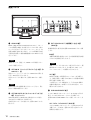
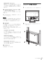
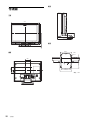
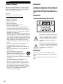
1
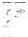
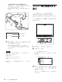
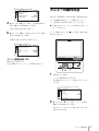
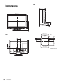
3-113-853-02 (1)
LCD Monitor
取扱説明書
2 ページ ________________________________________ JP
Operating Instructions
Page 28 ______________________________ GB
お買い上げいただきありがとうございます。
電気製品は安全のための注意事項を守らないと、
火災や人身事故になることがあります。
この取扱説明書には、事故を防ぐための重要な注意事項と製品の取り扱いかたを
示してあります。この取扱説明書をよくお読みのうえ、製品を安全にお使いくだ
さい。お読みになったあとは、いつでも見られるところに必ず保管してください。
付属の CD-ROM には、LMD-2030W の取扱説明書(日本語、英語、フランス語、
ドイツ語、イタリア語、スペイン語、中国語簡体字、中国語繁体字、韓国語)が記
録されています。詳しくは、別冊の「CD-ROM マニュアルの使いかた」をご覧く
ださい。
The supplied CD-ROM includes the Operating Instructions for the LMD-2030W
(English, Japanese, French, German, Italian, Spanish, Simplified Chinese, Traditional
Chinese and Korean versions).
For more details, refer to “Using the CD-ROM Manual”.
LMD-2030W
© 2007 Sony Corporation
日本語
安全のために
ソニー製品は正しく使用すれば事故が起きないように、
安全には十分配慮して設計されています。しかし、電気
警告表示の意味
製品はまちがった使いかたをすると、火災や感電などに
より死亡や大けがなど人身事故につながることがあり、
この取扱説明書および製品では、次のような表示
危険です。
事故を防ぐために次のことを必ずお守りください。
文をお読みください
をしています。表示の内容をよく理解してから本
安全のための注意事項を守る
4 〜 6 ページの注意事項をよくお読みください。製品全般
この表示の注意事項を守らないと、火災や感電な
の安全上の注意事項が記されています。
7 ページの「使用上のご注意」もあわせてお読みくださ
どにより死亡や大けがなど人身事故につながるこ
い。
とがあります。
定期点検をする
長期間安全に使用していただくために、定期点検を実施
することをおすすめします。点検の内容や費用について
この表示の注意事項を守らないと、感電やその他
は、お買い上げ店またはソニーのサービス窓口にご相談
ください。
えたりすることがあります。
故障したら使わない
の事故によりけがをしたり周辺の物品に損害を与
注意を促す記号
すぐに、お買い上げ店またはソニーのサービス窓口にご
連絡ください。
万一、異常が起きたら
行為を禁止する記号
• 煙が出たら
• 異常な音、においがしたら
• 内部に水、異物が入ったら
• 製品を落としたり、キャビネットを破損したと
きは
• 電源を切ります。
• 電源コードや接続ケーブルを抜きます。
• お買い上げ店またはソニーのサービス窓口にご相談くだ
さい。
2
安全のために
行為を指示する記号
目次
警告..................................................................................4
注意..................................................................................5
その他の安全上のご注意......................................................7
使用上のご注意(性能を保持するために).........................7
液晶画面について............................................................................... 7
液晶画面の輝点・滅点について............................................... 7
お手入れのしかた............................................................................... 7
ラックマウントについて............................................................... 8
破棄するときは .................................................................................... 8
特長.........................................................................................8
各部の名称と働き ..............................................................10
前面パネル ............................................................................................ 10
入力信号と調整・設定項目 ...................................................... 11
後面パネル ............................................................................................ 12
ラックへの取り付け ..........................................................13
電源コードの接続 ..............................................................14
入力アダプターの取り付け...............................................14
基本設定の選択 ..................................................................15
JP
メニュー表示言語の切り換え ...........................................16
メニューの操作方法 ..........................................................17
メニューを使った調整.......................................................19
項目一覧.................................................................................................. 19
調整と設定 ............................................................................................ 19
設定状態メニュー .............................................................. 19
ホワイトバランスメニュー......................................... 19
ユーザーコントロールメニュー.............................. 20
ユーザー設定メニュー.................................................... 20
リモートメニュー .............................................................. 21
キーロックメニュー......................................................... 21
故障かな?と思ったら.......................................................22
保証書とアフターサービス...............................................22
保証書 ....................................................................................................... 22
アフターサービス............................................................................ 22
主な仕様..............................................................................23
寸法図..................................................................................26
目次
3
警告
通気孔をふさがない
通気孔をふさぐと内部に熱がこもり、火災
や故障の原因となることがあります。風通
しをよくするために次の項目をお守りくだ
さい。
• 壁から 10cm 以上離して設置する。
• 密閉された狭い場所に押し込めない。
• 毛足の長い敷物(じゅうたんや布団など)
の上に設置しない。
• 布などで包まない。
油煙、湯気、湿気、ほこりの多い場
所では設置・使用しない
上記のような場所に設置すると、火災や感
電の原因となります。
取扱説明書に記されている仕様条件以外の
環境での使用は、火災や感電の原因となり
ます。
電源コードを傷つけない
電源コードを傷つけると、火災や感電の原
因となることがあります。
• 設置時に、製品と壁やラック、棚などの
安全アースを接続しないと、感電すること
があります。
次の方法でアースを接続してください。
• 電源コンセントが3極の場合
指定の電源コードを使用することで安全
アースが接続されます。
• 電源コンセントが2極の場合
ソニーのサービス担当者または営業担当者
にご相談ください。
高圧に注意する
ない。
• 重いものをのせたり、引っ張ったりしな
サービスマン以外の方は裏ぶたを開けない
でください。内部には高圧部品が数多くあ
い。
• 熱器具に近づけたり、加熱したりしない。
• 電源コードを抜くときは、必ずプラグを
り、万一触ると危険です。
店またはソニーのサービス窓口に交換をご
依頼ください。
電源コードのプラグおよびコネク
ターは突きあたるまで差し込む
まっすぐに突きあたるまで差し込まないと、
火災や感電の原因となります。
内部を開けない
内部には電圧の高い部分があり、キャビ
ネットや裏ぶたを開けたり改造したりする
と、火災や感電の原因となることがありま
す。内部の調整や設定、点検、修理はお買
い上げ店またはソニーのサービス窓口にご
依頼ください。
警告
安全アースを接続する
間に、はさみ込まない。
• 電源コードを加工したり、傷つけたりし
持って抜く。
万一、電源コードが傷んだら、お買い上げ
4
• あお向けや横倒し、逆さまにしない。
注意
不安定な場所に設置しない
ぐらついた台の上や傾いたところなどに設
置すると、倒れたり落ちたりしてケガの原
因となることがあります。
また、設置・取付け場所の強度を充分にお
確かめください。
指定された電源ケーブル、接続ケー
ブルを使う
設置は専門の工事業者に依頼する
設置については、必ずお買い上げ店または
ソニーの業務用製品ご相談窓口にご相談く
ださい。
壁面や天井などへの設置は、本機と取り付
け金具を含む重量に充分耐えられる強度が
あることをお確かめください。充分な強度
がないと、落下して、大けがの原因となり
ます。
また、1 年に 1 度は、取り付けがゆるんで
ないことを点検してください。
この取扱説明書に記されている電源ケーブ
ル、接続ケーブルを使わないと、火災や故
障の原因となることがあります。
入力アダプターを取り付ける際には
電源を切って電源プラグを抜く
入力アダプターを取り付ける際にはモニ
ターの電源を切り、電源プラグを抜いてく
ださい。モニターの電源を入れたまま入力
アダプターを取り付けると感電の原因とな
ることがあります。
転倒、移動防止の処置をする
コード類は正しく配置する
大型の製品をラックに取り付け・取りはず
しするときは、転倒・移動防止の処置をし
電源コードや接続ケーブルは、足に引っか
けると本機の落下や転倒などによりけがの
ないと、倒れたり、動いたりして、けがの
原因となることがあります。
原因となることがあります。
十分注意して接続・配置してください。
安定した姿勢で注意深く作業してください。
また、ラックの設置状況、強度を充分にお
確かめください。
安定した場所に設置する
表示された電源電圧で使用する
製品の表示と異なる電源電圧で使用すると、
火災や感電の原因となります。
製品が倒れたり、搭載した機器が落下して
けがをすることがあります。
十分な強度がある水平な場所に設置してく
ださい。
内部に水や異物を入れない
直射日光の当たる場所や熱器具の近
くに設置・保管しない
水や異物が入ると火災や感電の原因となる
ことがあります。
内部の温度が上がり、火災や故障の原因と
なることがあります。
万一、水や異物が入ったときは、すぐに電
源を切り、電源コードや接続コードを抜い
ぬれた手で電源プラグをさわらない
て、お買い上げ店またはソニーのサービス
窓口にご相談ください。
ぬれた手で電源プラグを抜き差しすると、
感電の原因となることがあります。
注意
5
接続の際は電源を切る
電源コードや接続コードを接続するときは、
電源を切ってください。感電や故障の原因
となることがあります。
お手入れの際は、電源を切って電源
プラグを抜く
電源を接続したままお手入れをすると、感
電の原因となることがあります。
移動の際は電源コードや接続コード
を抜く
コード類を接続したまま本機を移動させる
と、コードに傷がついて火災や感電の原因
となることがあります。
定期的に内部の掃除を依頼する
長い間、掃除をしないと内部にホコリがた
まり、火災や感電の原因となることがあり
ます。1 年に 1 度は、内部の掃除をお買い
上げ店またはソニーのサービス窓口にご依
頼ください(有料)。
特に、湿気の多くなる梅雨の前に掃除をす
ると、より効果的です。
水のある場所に設置しない
水が入ったり、ぬれたりすると、火災や感
電の原因となることがあります。雨天や降
雪中、海岸や水辺での使用は特にご注意く
ださい。
密閉環境に設置する際は注意する
本機をラックやモニター棚に収納した際、
上下および周辺の機器によりモニター周辺
の通風が妨げられ動作温度が上がり、故障
や発熱の原因となる可能性があります。
本機の動作条件温度 0 ℃から 35 ℃を保つよ
うに上下および周辺機器との隙間を充分に
取り、通気孔の確保や通気ファンの設置等
の配慮をしてください。
6
注意
その他の安全上のご注意
使用上のご注意(性能を保
持するために)
本機をラックに設置するときは、本機の上下に 4.4cm 以
上の空間を確保してください。
本機の幅および奥行きより広いところに設置してくださ
い。
本機が設置面からはみだしていると、本機が傾いたり転
倒することにより、けがの原因となることがあります。
液晶画面について
液晶画面を太陽にむけたままにすると、液晶画面を傷め
てしまいます。窓際や室外に置くときなどはご注意くだ
さい。
液晶画面を強く押したり、ひっかいたり、上にものを置
いたりしないでください。画面にムラが出たり、液晶パ
ネルの故障の原因になります。
寒い所でご使用になると、横縞が見えたり、画像が尾を
引いて見えたり、画面が暗く見えたりすることがありま
すが、故障ではありません。温度が上がると元に戻りま
す。
固定された画像または静止画を長時間表示した場合、残
像や焼きつきの原因となることがあります。
使用中に画面やキャビネットがあたたかくなることがあ
りますが、故障ではありません。
液晶画面の輝点・滅点について
本機の液晶パネルは有効画素 99.99%以上の非常に精密度
の高い技術で作られていますが、画面上に黒い点が現れ
たり(画素欠け)、常時点灯している輝点(赤、青、緑な
ど)や滅点がある場合があります。また、液晶パネルの
特性上、長期間ご使用の間に画素欠けが生じることもあ
ります。これらの現象は故障ではありませんので、ご了
承の上本機をお使いください。
お手入れのしかた
お手入れをする前に、必ず電源プラグをコンセントから
抜いてください。
モニター画面のお手入れについて
モニターの画面は反射による映り込みを抑えるため、特
殊な表面処理を施してあります。誤ったお手入れをした
場合、性能を損なうことがありますので、以下のことを
お守りください。
• スクリーン表面についた汚れは、クリーニングクロスや
メガネ拭きなどの柔らかい布で軽く拭いてください。
• 汚れがひどいときは、クリーニングクロスやメガネ拭き
などの柔らかい布に水を少し含ませて、拭きとってくだ
さい。
• アルコールやベンジン、シンナー、酸性洗浄液、アルカ
リ性洗浄液、研磨剤入り洗浄剤、化学ぞうきんなどはス
その他の安全上のご注意 / 使用上のご注意(性能を保持するために)
7
クリーン表面を傷めますので、絶対に使用しないでくだ
さい。
特長
外装のお手入れについて
• 乾いた柔らかい布で軽く拭いてください。汚れがひどい
ときは、薄い中性洗剤溶液を少し含ませた布で拭きと
り、乾いた布でカラ拭きしてください。
• アルコールやベンジン、シンナー、殺虫剤をかけると、
表面の仕上げを傷めたり、表示が消えてしまうことがあ
るので、使用しないでください。
• 布にゴミが付着したまま強く拭いた場合、傷が付くこと
があります。
• ゴムやビニール製品に長時間接触させると、変質した
り、塗装がはげたりすることがあります。
ラックマウントについて
ラックマウント時は、性能維持のため上下に 1 U 空けて、
通気孔の確保や通気ファンの設置を行ってください。
破棄するときは
LMD-2030W(20 型)は高精細、高性能の放送/業務用マ
ルチフォーマット液晶モニターです。デジタルとアナロ
グの主要放送信号および HDMI1) 入力に対応し、さまざま
な照明環境で鮮明に映像を再現できます。
1) HDMI、HDMI ロゴ、および High-Definition Multimedia Interface は、
HDMI Licensing LLC の商標または登録商標です。
高性能 LCD パネル
高精細、広視野角特性と高速応答で優れた色再現を提供
します。
マルチフォーマット対応
ビデオ、Y/C、RGB、コンポーネント、HDMI の各入力
信号に対応します。
別売の SDI 入力アダプター(BKM-320D)を取り付ける
ことにより SDI 信号を入力することができます。
NTSC/PAL の 2 つのカラー方式に対応し、入力信号に
合った方式で画像を再現します。
• 一般の廃棄物と一緒にしないでください。
ごみ廃棄場で処分されるごみの中にモニターを捨てない
◆ 詳しくは「信号方式」(25 ページ)をご覧ください。
でください。
• 本機の蛍光管の中には水銀が含まれています。破棄の際
外部同期信号入力端子
は、地方自治体の条例または規則に従ってください。
外部同期信号発生器などからの同期信号を入力できます。
EXT SYNC ボタンを押すと、外部同期で動作します。
自動終端解放(
マークの付いた端子のみ)
後面の入力端子は、出力端子に何も接続していないとき
は、内部で 75Ω で終端されています。出力端子にケーブ
ルが接続されると、内部の終端が自動的に解放され、入
力端子に入力された信号が出力端子に出力されます
(ループスルー)
。
外部リモート機能
接続した外部機器からの操作で、選択したい入力やアス
ペクトなどを直接選ぶことができます。
チルト機能付きモニタースタンド
チルト機能のついたモニタースタンドを標準装備してい
ますので、そのままデスクトップに置いて使用できます。
19 インチラックにマウントする場合は、スタンドを取り
外して使用します。
8
特長
ラックマウント
VESA(100 × 100 mm)に準拠します。
EIA19 インチラックへも搭載できます(別売マウンティ
ングブラケットを使用)。
◆ 詳しくは、「ラックへの取り付け」(13 ページ)をご覧くださ
い。
3 色タリーランプ
赤、緑、アンバーと 3 色表示できるタリーランプを搭載
しています。放送中かどうかなど、各入力画像のモニタ
リング状態を瞬時に把握できます。
ブルーオンリーモード
R/G/B の各画素を青信号で動作させ、白黒画像として表
示するモードです。
色の濃さ(クロマ)や色相(フェーズ)の調整、VTR ノ
イズ成分の監視に便利です。
マーカー機能
センターマーカー、4:3 信号での 16:9 マーカー、16:9 信号
での 4:3 マーカーを表示することができます。
スキャン切り換え機能
アンダースキャン、オーバースキャン、フルスクリーン
の3種類の画面サイズが選択できます。
色温度/ガンマ切り換え機能
高、低 2 つの色温度を用途や好みに応じて選択/設定す
ることができます。
あらかじめ設定された 5 つのガンマを用途やお好みに応
じて選択することができます。
アスペクト切り換え機能
入力信号に応じて 4:3 と 16:9 の画角を切り換えることがで
きます。
スクリーンメニュー表示機能
画面にメニューを出して、接続するシステムに最適な
ディスプレイの設定や調整をすることができます。
メニュー表示言語の選択
メニュー画面より、英語、フランス語、ドイツ語、スペ
イン語、イタリア語、日本語、中国語の 7 か国語から選
んで画面を表示できます。
キーロック機能
各種調整キーの誤操作を防ぐため、調整キーをロックで
きます。
特長
9
各部の名称と働き
前面パネル
1
MENU
LINE A
RGB/
HDMI COMPONENT
SDI
EXT
SYNC
BLUE
ONLY
SCAN
VOLUME
ASPECT
ENTER
RESET
qd qs qa 0 9 8 7 6
POWER
KEY
INHIBIT
5
4 3 2
qf
a タリーランプ
MENU(メニュー)ボタン
入力画面のモニター状態を色によって表示することがで
きます。
押すと、メニューが表示されます。
もう一度押すとメニューは消えます。
リモートメニューの設定に応じて、赤、緑、アンバーで
点灯します。
RESET(リセット)ボタン
b POWER(電源)スイッチとインジケーター
調整した項目の調整値を調整前の状態に戻すときに
押します。
スイッチを押すと電源が入り、インジケーターが点灯し
ます。もう一度押すと、電源が切れます。
メニュー画面の項目を調整中(画面に表示中)に働
きます。
c KEY INHIBIT(キーロック)インジケーター
ENTER(決定)ボタン
キーロックが働いているときに点灯します。
メニューで内容を決定するときに使います。
◆ キーロックについては「キーロックメニュー」(21 ページ)
をご覧ください。
d VOLUME(音量)調整ボタン
+を押すと音量が大きくなり、−を押すと小さくなりま
す。
e メニュー操作ボタン
メニュー画面の表示や設定をします。
M/m/</,(矢印)ボタン
メニューに表示されるカーソルを動かすときや、項
目の数値を変えるときに使います。
10
各部の名称と働き
f ASPECT(アスペクト)切り換えボタン
画面のアスペクト(縦横比)について、4:3 または 16:9 を
選びます。
g SCAN(スキャン)切り換えボタン
画像のスキャンサイズを変えることができます。
このボタンを押すとオーバー(5%オーバースキャン)
、
アンダー(− 3%アンダースキャン)
、メニューの「ス
キャン」
(21 ページ)で設定したフルスクリーン表示にな
ります。
h BLUE ONLY(ブルーオンリー)ボタン
k RGB/COMPONENT ボタン
このボタンを押すと、赤と緑の信号がカットされ、青信
RGB/COMPONENT 入力端子からの信号をモニターする
号のみが白黒画像として表示されます。色の濃さ(クロ
マ)や色相(フェーズ)の調整、VTR ノイズの監視が容
易に行えます。
ときに押します。
l HDMI ボタン
HDMI IN 端子からの信号をモニターするときに押します。
i EXT SYNC(外部同期)ボタン
EXT SYNC IN 端子から入力された外部同期信号で同期を
とるときはこのボタンを押します。
m LINE A ボタン
EXT SYNC ボタンはコンポーネント /RGB 入力時のみ動
作します。
す。
LINE A 入力端子からの信号をモニターするときに押しま
n スピーカー
j SDI ボタン
前面の入力切り換えボタン(j SDI ボタン、k RGB/
OPTION IN 端子からの信号をモニターするときに押しま
す。
COMPONENT ボタン、l HDMI ボタン、m LINE A ボ
タン)で選んだ入力の音が出ます。
入力信号と調整・設定項目
入
項目
コントラスト
ブライト
クロマ
フェーズ
ビデオ、Y/C
色温度
コンポーネントレベル *1
D1
SD
HD
DVI*6
a
a
a
a
a
a
a
×
×
a
a
a
a
a
a
a
a
a
a
a
×
a
a
a
×
×
×
×
×
×
×
×
×
a
a
a
a
a
a
×
×
a
a
a
a
a
×
a
a
a
a
×
×
a
a
a
×
×
×
×
×
×
×
×
×
×
×
×
×
×
×
a
a
a
a
a
a
a
a
a
a*2
a
a
a*5
a
a
a
a
a
a
a
a
a
a
a*2
a
a
a*5
a
a
a
a
a
a
a
a
a
a
a
a
a
a
a
a*2
a
a
a*5
a
×
×
×
a
a
a
a
a
a
a
a
a
a
a
映像ディレイ最小 *3
a
a
a
a
a
a
EXT SYNC
×
×
ASPECT
マーカー
BLUE ONLY
a :調整・設定できる項目
× :調整・設定できない項目
HDMI
HD
(480/60I)
SCAN
SDI*4
RGB
SD
a
ガンマ
号
HD
(NTSC)
NTSC セットアップ
コンポーネント
信
SD
(NTSC)
アパーチャー
白黒信号
力
×
a
(480/60I)
×
×
×
×
×
×
×
*1
*2
*3
*4
*5
コンポーネント信号(480/60I)入力のときのみ切り換えできます。
480/60P、576/50P 信号入力のとき切り換えできます。
インターレース信号のみ切り換えできます。
BKM-320D が装着されているとき、入力が可能です。
1080I 信号入力のときは、切り換えできません。
(映像ディレイ最小の設定は、「オン」に固定)
*6 HDMI IN 端子に DVI 変換ケーブルを接続して PC 信号を入力したと
き、調整が可能です。
各部の名称と働き
11
後面パネル
8
7
LINE A
IN
6 5 4 3 2
PARALLEL REMOTE
RGB/COMPONENT
IN
OUT
G/Y
IN
OPTION
OUT
1
AUDIO IN
OPTION IN
IN
VIDEO
OUT
IN
OUT
IN
B/PB
OUT
IN
OUT
IN
EXT
SYNC
OUT
AC IN
IN
a HDMI IN 端子
HDMI(High-Definition Multimedia Interface)とは、デ
ジタル機器間で映像/音声信号をデジタルのまま 1 本の
ケーブルで送ることができるインターフェースです。高
品質な映像や音声が楽しめます。デジタル画像信号の暗
号化記述を使用した著作権保護技術である HDCP にも対
応しています。
AUDIO
R/PR
AUDIO
OUT
d EXT SYNC IN/OUT(外部同期入 / 出力)端子
(BNC 型)
外部同期信号を使う場合は前面の EXT SYNC ボタンを押
します。
IN 端子
本機を外部同期で動作させるときに外部同期信号発生器
などからの基準信号を入力します。
ご注意
HDMI ケーブル(別売)は、HDMI ロゴを取得したケー
ご注意
ブルをご使用ください。
本機へジッターなどがあるビデオ信号を入力すると、画
b OPTION IN(インプットアダプター入力)端子(D-
像が乱れることがあります。その場合は、TBC(タイ
ムベースコレクター)の使用をおすすめします。
sub 9 ピン、凹)
別売のソニーインプットアダプター BKM-320D を取り付
OUT 端子
けると SDI 信号を入力できます。
信号をモニターする場合には、前面の SDI ボタンを押し
IN 端子に接続した同期信号のループスルー出力端子で
す。本機と同期して動作させる他のビデオ機器の外部同
ます。
期入力端子と接続します。
この端子にケーブルを接続すると、入力の 75Ω 終端が
ご注意
BKM-320D 以外の機器を取り付けないでください。取り
付けると故障の原因になります。
自動的に解放され、IN 端子に入力された信号が、この
端子から出力されます。
e RGB/COMPONENT 端子
c OPTION AUDIO IN(オプションオーディオ入力)
端子(ピンジャック)
OPTION IN 端子に BKM-320D が装着されている場合、
その音声入力に使用する入力端子です。
音声信号をモニターする場合には、前面の SDI ボタンを
押します。
アナログ RGB またはコンポーネント (Y/PB/PR) の入出力
端子、およびそれぞれのループスルー出力端子です。
前面の RGB/COMPONENT ボタンを押してモニターしま
す。
G/Y、B/PB、R/PR IN/OUT(BNC 型)
アナログ RGB およびコンポーネント (Y/PB/PR) の入出
力端子です。入力時は、通常 G/Y 信号に含まれている
同期信号で動作します。
12
各部の名称と働き
AUDIO IN/OUT(ピンジャック)
映像信号としてアナログ RGB またはコンポーネントを
入力する場合に、音声信号の入力端子として使用しま
す。VTR など、外部機器の音声出力および入力端子と
接続します。
ラックへの取り付け
1
ネジ(4 か所)をはずして、スタンドを取りはずす。
f PARALLEL REMOTE(パラレルリモート)端子
(モジュラーコネクター 8 ピン)
パラレルコントロールスイッチを構成してモニターを外
部操作します。
◆ ピン配列と出荷時の各ピンへの機能の割付について詳しくは、
24 ページをご覧ください。
ご注意
安全のために、周辺機器を接続する際は、過大電圧を持
つ可能性があるコネクターをこの端子に接続しないでく
ださい。接続については本書の指示に従ってください。
g LINE A 端子
Y/C 分離入力、コンポジットビデオ信号と音声信号のラ
イン入力端子、およびそれぞれのループスルー端子です。
2
マウンティングブラケットを取り付けてから、ラッ
クに取り付ける。
前面の LINE A ボタンを押してモニターします。
Y/C 入力と VIDEO 入力を同時に接続した場合、Y/C 入
力が優先となります。
Y/C IN/OUT(4 ピンミニ DIN)
Y/C 分離の入出力端子です。VTR やビデオカメラ、他
のモニターなど外部機器の Y/C 分離出力および入力端
子と接続します。
VIDEO IN/OUT (BNC 型 )
コンポジットビデオの入出力端子です。VTR やビデオ
カメラ、他のモニターなど、外部機器のコンポジット映
像出力および入力端子と接続します。
AUDIO IN/OUT(ピンジャック)
LINE
A
LINE
RGB/
B COMP
ONEN
音声の入出力端子です。VTR などの外部機器の音声出
力および入力端子と接続します。
T
SDI
EXT
SYNC
BLUE
ONLY
SCA
N
ASP
ECT
MEN
RESE
U
T
VOLU
ENTE
ME
R
KEY
INHIB
IT
POW
ER
h AC IN ソケット
付属の電源コードをつなぎます。
ラックへの取り付け
13
電源コードの接続
1
AC 電源コードを後面の AC IN ソケットに差し込み、
AC 電源プラグホルダーを AC 電源コードに取り付け
る。
入力アダプターの取り付
け
入力アダプターを取り付ける前に必ず電源ケーブルを抜
いてください。
AC IN ソケット
LINE A
IN
VIDEO OUT
AC IN
IN
AUDIO OUT
AC 電源コード
AC プラグホルダー(付属)
ご注意
2
固定レバーがロックするまで、AC 電源プラグホル
ダーをはめこむ。
LINE A
IN
VIDEO OUT
AC IN
IN
AUDIO OUT
電源コードをはずすには
AC 電源プラグホルダーの固定レバーを両側からはさんで
ロックをはずし、引き抜きます。
14
電源コードの接続 / 入力アダプターの取り付け
BKM-320D 以外の機器を取り付けないでください。取り
付けると故障の原因になります。
基本設定の選択
はじめてお使いになるときはお使いになる地域の選択を
行ってください。
地域を選択すると、メニュー内の各項目がお使いの地域
に合った値に設定されます。
地域別基本設定値
MENU
VOLUME
POWER
KEY
INHIBIT
ENTER
RESET
3
2~3
1
1
5
1
4
3
2
POWER スイッチを押す。
本機の電源が入り、SELECT SETTING 画面が表示
3
されます。
色温度
1NORTH AMERICA
2LATIN AMERICA
PAL&PAL-N AREA
NTSC&PAL-M AREA
LOW
BETA7.5
7.5
ARGENTINA
LOW
SMPTE
0
PARAGUAY
LOW
SMPTE
0
URUGUAY
LOW
SMPTE
0
OTHER AREA
LOW
BETA7.5
7.5
LOW
SMPTE
0
NTSC AREA
LOW
BETA7.5
7.5
PAL AREA
LOW
SMPTE
0
HIGH
SMPTE
0
3AFRICA AUSTRALASIA
EUROPE MIDDLE-EAST
4ASIA EXCEPT JAPAN
5JAPAN
コンポー NTSC
ネントレ セット
ベル
アップ
1 北アメリカ
S E L EC T S E T T I NG
xN O R T H A M E R I C A
• L A T I N AMER I CA
• AFR I CA AUSTRA L AS I A
EUROP E M I DD L E - E A S T
• AS I A EXCEPT J APAN
• J APAN
2 ラテンアメリカ
3 アフリカ、オーストラ
リア / ニュージーランド、
ヨーロッパ、中東、ロシア
4 日本を除くアジア
5 日本
2
M または m ボタンを押して、
本機をお使いになる地域
を選び、, または ENTER ボタンを押す。
LATIN AMERICA(ラテンアメリカ)
、ASIA
EXCEPT JAPAN(日本以外のアジア)が選ばれた
ときは次の画面が表示されます。
2LATIN AMERICA が選ばれたとき:
PAL、PAL-N 地域
L A T I N AMER I CA
xP A L & P A L - N A R E A
ARGEN T I NA
P ARAGUA Y
URUGUA Y
• NTSC&PA L - M AREA
OTHER AREA
アルゼンチン
パラグアイ
ウルグアイ
NTSC、PAL-M 地域
他の地域
基本設定の選択
15
4ASIA EXCEPT JAPAN が選ばれたとき:
下の地図でグレーに色付けされた地域でお使いの場
合は、NTSC AREA を選んでください。
他の地域でお使いの場合は、PAL AREA を選んでく
ださい。
メニュー表示言語の切り
換え
メニュー画面やメッセージの表示言語を 7 言語
(ENGLISH、FRANÇAIS、DEUTSCH、ESPAÑOL、
ITALIANO、日本語、中文)の中から選ぶことができま
す。
メニュー画面のイラスト上の x マーク部分に現在の設定
値が表示されます。
AS I A EXCEPT
xN T S C A R E A
• PAL
J APAN
AREA
NTSC 地域
PAL 地域
MENU
VOLUME
POWER
KEY
INHIBIT
ENTER
RESET
3
M または m ボタンを押してさらに地域を限定し、,
3~5
または ENTER ボタンを押す。
SELECT SETTING 画面が消えて、自動的にメ
ニュー内の各項目が、選択した地域に合った値に設
定されます。
1
2
2
1
POWER スイッチを押して、電源を入れる。
MENU ボタンを押す。
メニュー画面が表示されます。
現在選択されているメニューが黄色いボタンで表示
ご注意
地域を間違えて設定した場合は、メニューを使い以下の
項目を変更してください。
されます。
色温度(19 ページ)
コンポーネントレベル(20 ページ)
NTSC セットアップ(20 ページ)
◆ 設定値については「地域別基本設定値」(15 ページ)をご覧
ください。
3
USER CONTROL
CONTROL
· CONTRAST
· BRIGHT
· CHROMA
· PHASE
· APERTURE
x
x
x
x
xxx
· BACKLIGHT
x
M ボタンまたは m ボタンを押して USER CONFIG 1/2
(ユーザー設定 1/2)のメニューを選び、, または
ENTER ボタンを押す。
選んだメニューの設定項目(アイコン)が黄色で表
示されます。
16
メニュー表示言語の切り換え
USER CONFIG (1/2) Rr
· RGB/COMP SEL
· COMP LEVEL
· NTSC SETUP
· GAMMA
· F O R M AT D I S P
xL A N G U A G E
4
xxxx
xxxxx
x
x
xxxx
ENGLISH
M ボタンまたは m ボタンを押して「LANGUAGE」を
選び、, または ENTER ボタンを押す。
メニューの操作方法
本機では、画質調整や入力信号の設定、初期設定の変更
など、各種調整や設定をメニュー画面で行います。メ
ニュー画面表示の言語を切り換えることもできます。
◆ 表示言語を変えるには、「メニュー表示言語の切り換え」(16
ページ)をご覧ください。
選んだ項目が黄色で表示されます。
5
メニュー画面のイラスト上の x マーク部分に現在の設定
Mボタンまたはmボタンを押して表示させたい言語を
選び、ENTER ボタンを押す。
値が表示されます。
画面表示が選んだ言語に切り換わります。
ユーザー設定 (1/2)Rr
・RGB/COMP切換
・コンポーネントレベル
・NTSCセットアップ
・ガンマ
・フォーマット表示
x言語
xxxx
xxxxx
x
x
xxxx
日本語
メニュー画面を消すには
MENU ボタンを押します。
MENU
約 1 分間操作をしないとメニューは自動的に消えます。
VOLUME
POWER
KEY
INHIBIT
ENTER
RESET
2~4
1
1
MENU ボタンを押す。
メニュー選択画面が表示されます。
現在選択されているメニューが黄色いボタンで表示
されます。
ユーザーコントロール
コントロール
・コントラスト
・ブライト
・クロマ
・フェーズ
・アパーチャー
x
x
x
x
xxx
x
・バックライト
2
M ボタンまたは m ボタンを押してメニューを選び、
, または ENTER ボタンを押す。
選んだメニューのアイコンが黄色で表示され、設定
項目が表示されます。
メニューの操作方法
17
設定値をリセットする
ユーザー設定 (1/2)Rr
・RGB/COMP切換
・コンポーネントレベル
・NTSCセットアップ
・ガンマ
・フォーマット表示
x言語
3
xxxx
xxxxx
x
x
xxxx
日本語
項目を選ぶ。
M ボタンまたは m ボタンを押して設定項目を選び、
, または ENTER ボタンを押します。
変更する項目が黄色で表示されます。
ご注意
項目が複数メニューページにおよぶ場合、M ボタン
または m ボタンを押して必要なメニューページに入
ります。
4
設定項目の調整や設定をする。
数値を変更する項目の場合:
数値を大きくするときは、M ボタンを押します。
数値を小さくするときは、m ボタンを押します。
ENTER ボタンを押すと確定され、元の画面に戻り
ます。
設定を選ぶ場合:
M ボタンまたは m ボタンを押して設定を選び、
ENTER ボタンを押します。
ご注意
• 設定項目で青色表示の項目はアクセスできない状
態を意味します。白色表示にかわるとアクセスが
可能になります。
• キーロックがオンに設定されている場合、すべて
設定項目が青色表示になります。設定変更が必要
な場合は、キーロックをオフに設定しなおしてか
ら行ってください。
◆ キーロックについては、
「キーロックメニュー」(21
ページ)をご覧ください。
メニュー画面を消すには
MENU ボタンを押します。
約 1 分間操作をしないとメニューは自動的に消えます。
設定値の記憶について
設定値は自動的に本体に記憶されます。
18
メニューの操作方法
メニュー内の項目を調整中に RESET ボタンを押すと調整
前の値に戻ります。
メニューを使った調整
項目一覧
本機のスクリーンメニューは次のような構成になってい
ます。
キーロック
キーロック
調整と設定
設定状態メニュー
本機の現在の設定状況を表示します。表示される項目は
以下のとおりです。
設定状態(表示のみ)
信号フォーマット
色温度
ガンマ
コンポーネントレベル
NTSC セットアップ
RGB/COMP 切換
ディスプレイモード
ディスプレイ
オプション
設定状態 (1/2) Rr
信号フォーマット xxxxxxxxx
色温度
xxxxxxxx
xxx
x
xxxxx
x
xxxx
xxxx
ガンマ
コンポーネントレベル
NTSCセットアップ
RGB/COMP切換
ディスプレイモード
設定状態 (2/2) Rr
ディスプレイ
LMD-2030W
オプション
BKM-320D
ホワイトバランス
色温度
マニュアル調整
ユーザーコントロール
コントロール
ユーザー設定
RGB/COMP 切換
コンポーネントレベル
NTSC セットアップ
ガンマ
• 信号フォーマット
• 色温度
• ガンマ
• コンポーネントレベル
• NTSC セットアップ
• RGB/COMP 切換
• ディスプレイモード
• ディスプレイ
• オプション
ホワイトバランスメニュー
フォーマット表示
言語
画質のホワイトバランスを調整するメニューです。
ホワイトバランスの調整には測定器が必要です。
マーカー
センターマーカー
推奨品:コニカミノルタ社製カラーアナライザー CA-210
マーカーレベル
スキャン
映像ディレイ最小
ホワイトバランス
x色温度
マニュアル調整
・ゲイン調整...
・バイアス調整...
・標準値をコピー
xxxxxx
xxx
リモート
1 ピン
2 ピン
3 ピン
4 ピン
6 ピン
サブメニュー
設定
色温度
色温度を「高」、
「低」、「ユーザー設定」か
ら設定します。
7 ピン
8 ピン
メニューを使った調整
19
サブメニュー
設定
マニュアル調整
色温度を「ユーザー設定」にしたとき、表
示が青色から白色にかわり、調整できるよ
うになります。
• ゲイン調整...:カラーバランス(ゲ
イン)を調整します。
• バイアス調整...:カラーバランス
(バイアス)を調整します。
• 標準値をコピー:「高」または「低」を
選択すると、選択された色温度のホ
ワイトバランスデータが、「ユー
ザー設定」にコピーされます。
ユーザーコントロールメニュー
ユーザー設定 (1/2) Rr
xRGB/COMP切換
・コンポーネントレベル
・NTSCセットアップ
・ガンマ
・フォーマット表示
・言語
ユーザー設定 (2/2) Rr
xマーカー
・センターマーカー
・マーカーレベル
・スキャン
・映像ディレイ最小
xxxx
xxxxx
x
x
xxx
xxx
xxx
xxx
x
xxxx
xxx
画質を調整するメニューです。
入力信号によって調整できない項目は青色で表示されま
す。
ユーザーコントロール
コントロール
xコントラスト
・ブライト
・クロマ
・フェーズ
・アパーチャー
x
x
x
x
xxx
サブメニュー
設定
RGB/COMP 切換
RGB/COMPONENT 入力端子からの信号
をモニターするときに、入力する信号に応
じて「RGB」または「COMP」(コンポー
ネント)を選択します。
コンポーネントレベル
以下の 3 種類のなかから、入力されている
コンポーネント信号の種類を選択します。
• SMPTE:100/0/100/0 のコンポーネン
ト信号のとき
• BETA 0:100/0/75/0 のコンポーネント
信号のとき
• BETA 7.5:100/7.5/75/7.5 のコンポーネ
ント信号のとき
NTSC セットアップ
NTSC 信号のセットアップのレベルを選択
します。日本は 0 で、アメリカでは 7.5 で
運用されています。このため輸入ソフトに
は 7.5 のものがあります。
ガンマ
画像に合わせて最適な状態を選びます。5
段階の中から選ぶことができます。設定値
が 3 のとき、CRT とほぼ同じガンマ(2.2)
となります。
フォーマット表示
フォーマットが表示されます。
• オン:常に表示されます。
• オフ:表示されません。
• オート:信号入力開始後約 10 秒間表示
されます。
言語
メニュー表示やメッセージの表示言語を以
下の 7 言語から選択できます。
• ENGLISH:英語
• FRANÇAIS:フランス語
• DEUTSCH:ドイツ語
• ESPAÑOL:スペイン語
• ITALIANO:イタリア語
• 日本語:日本語
• 中文:中国語
マーカー
フィルムのフレーム枠を画面に表示させる
とき、フィルムに合わせてアスペクト比を
選択できます。
ASPECT 切り換えボタンで 16:9 が選ばれ
ているとき
4:3、オフから選択します。
ASPECT 切り換えボタンで 4:3 が選ばれ
ているとき
16:9、オフから選択します。
センターマーカー
画像のセンターを表すマーカーを表示する
とき「オン」に設定します。表示しないと
きは「オフ」に設定します。
x
・バックライト
サブメニュー
設定
コントロール
画像を調整します。
• コントラスト:コントラストを調整しま
す。
• ブライト:明るさを調整します。
• クロマ:色の濃さを調整します。設定値
が大きくなると濃くなり、小さくな
ると薄くなります。
• フェーズ:色相(色あい)を調整します。
設定値が大きくなると緑がかり、小
さくなると紫がかります。
• アパーチャー:シャープネスを強調しま
す。設定値が大きくなるとくっきり
します。
• バックライト:バックライトを調整しま
す。設定値を変えるとバックライト
の明るさが変わります。
◆ 入力信号と調整・設定項目については、11 ページをご覧くだ
さい。
ユーザー設定メニュー
言語の選択などを設定します。
入力信号によって調整できない項目は青色で表示されま
す。
マーカーレベル
20
メニューを使った調整
「マーカー」と「センターマーカー」表示
の輝度を設定します。
設定値が小さくなると暗くなります。
1 〜 4、6 〜 8 ピンに各機能を割り付けられます。割り付
サブメニュー
設定
スキャン
画像のスキャンサイズを変更することがで
きます。
モードは「オフ」と「フルスクリーン」か
ら選択できます。
• オフ:オーバー、アンダーを切り換え
ます。
• フルスクリーン:オーバー、アンダー、
フルスクリーンを切り換えます。
映像ディレイ最小
(映像遅延最小)
信号を入力したとき、機器内部の画像処理
による遅延を最小にしたいとき設定しま
す。1080I 信号入力時は「オフ」を選択で
きません。
• オフ:画質優先のモードです。処理時
間は「オン」に設定したときより長
くなります。
• オン:処理時間が短くなります。ライ
ンフリッカーが見えるので、テロッ
プ制作などのラインフリッカー
チェック用途にもご使用いただけま
す。
4
x1ピン
・2ピン
・3ピン
・4ピン
・6ピン
・7ピン
・8ピン
xxxxx
xxxxx
xxxxxxx
xxxxxxx
xxxxxxxx
xxxxxxxxx
xxxx
リモート
• - - -(「- - -」は機能の割付なし。
)
• LINE A
• HDMI
• RGB/COMP
• 16:9
• 4:3
• タリー赤
• タリー緑
16
9
3
オーバー
スキャン
(5%オーバー
スキャン)
リモート
• アンダー
• オーバー
入力信号
4
け可能な機能は以下のとおりです。
• 16:9 マーカー
• 4:3 マーカー
• センターマーカー
16
9
3
• 外部同期
• ブルーオンリー
• フルスクリーン
• SDI
パラレルリモートを使用する場合は、配線が必要です。
アンダー
スキャン
(− 3%アン
ダースキャン)
4
◆ 詳しくは、24 ページをご覧ください。
16
9
3
出
キーロックメニュー
力
キーロック
xキーロック
状 フルスクリーン
xx
16
態
−
9
各種設定項目の変更が効かないように、キーロックをか
フルスクリーン
(1080)
けることができます。
オフあるいはオンを選択します。
1920
−
1080
「オン」に設定した場合、他のメニューの設定項目はすべ
て青色表示となり、変更できなくなります。
リモートメニュー
PARALLEL REMOTE 端子で機能を変更したいピンを選
択します。
メニューを使った調整
21
故障かな?と思ったら
お買い上げ店などにご相談いただく前に、次の事項をご
確認ください。
• 画面が緑色や紫色になる t ユーザー設定メニューの
「RGB/COMP 切換」(20 ページ)で正しい入力を選ん
でください。
• 操作ボタンを押しても操作できない t キーロックが働
いています。キーロックメニューでキーロックの設定を
オフに切り換えてください。
保証書とアフターサービ
ス
保証書
• この製品には保証書が添付されていますので、お買い上
げの際お受け取りください。
• 所定事項の記載内容をお確かめのうえ、大切に保存して
ください。
アフターサービス
調子が悪いときはまずチェックを
この説明書をもう一度ご覧になってお調べください。
それでも具合の悪いときはサービスへ
お買い上げ店、または添付保証書の「ソニー業務用製品
ご相談窓口のご案内」にあるソニーサービス窓口にご相
談ください。
部品の交換について
この製品は、修理の際に交換した部品を再生、再利用す
る場合があります。その際、交換した部品は回収させて
いただきます。
保証期間中の修理は
保証書の記載内容に基づいて修理させていただきます。
詳しくは保証書をご覧ください。
保証期間経過後の修理は
修理によって機能が維持できる場合は、ご要望により有
料修理をさせていただきます。
22
故障かな?と思ったら / 保証書とアフターサービス
RGB/COMPONENT 出力
主な仕様
RGB /コンポーネント出力
BNC 型(3)、ループスルー、75Ω
自動終端機能付き
AUDIO 出力
画像系
ピンジャック(1)、ループスルー
LCD パネル
a-Si TFT アクティブマトリックス
外部同期出力
画面サイズ
20.1 型
433 × 271 × 511 mm
内蔵スピーカー出力
(幅×高さ×対角)
1680 × 1050 ドット (WSXGA+)
89°/89°/89°/89°(typical)
解像度
視野角
スキャン
アスペクト
色再現性
アンダー
オーバー
− 3%
5%
16:10
1670 万色
入出力
0.5 W(モノラル)
その他
電源
AC100 − 240 V、50/60 Hz
消費電力
最大約 72 W、0.8 A − 0.4 A
最大外形寸法(幅/高さ/奥行き)
約 493 × 408 × 264 mm(最大突起部
含まず)
質量
動作条件
入力
Y/C 入力
VIDEO 入力
4 ピンミニ DIN (1)
BNC 型(1)、1 Vp-p ± 3 dB、負
AUDIO 入力
同期
ピンジャック(1)、− 5 dBu 47
湿度
気圧
保存・輸送条件
温度
湿度
kΩ 以上
RGB/COMPONENT 入力 BNC 型(3)
0.7 Vp-p ± 3 dB、
(Sync On Green
0.3 Vp-p 負同期)
気圧
付属品
ピンジャック(1)、− 5 dBu 47
kΩ 以上
OPTION IN 入力 D-sub 9 ピン(1)
、凹
OPTION AUDIO IN 入力
ピンジャック(1)
、− 5 dBu 47 kΩ
以上
外部同期入力
HDMI 入力
BNC 型(1)0.3 〜 4Vp-p 負極性 2 値
HDMI(1)
リモート入力
パラレルリモート
モジュラーコネクター 8 ピン(1)
30 〜 85%以下 ( 結露がないこと )
700 〜 1060 hPa
− 20 〜 +60 ℃
0 〜 90%
700 〜 1060 hPa
AC 電源コード (1)
CD-ROM (1)
CD-ROM マニュアルの使いかた (1)
保証書 (1)
別売アクセサリー
マウンティングブラケット MB-529
SDI 入力アダプター BKM-320D
本機は「高調波電流規格 JIS C 61000-3-2 適合品」です。
本機の仕様および外観は、改良のため予告なく変更する
ことがありますが、ご了承ください。
この装置は、情報処理装置等電波障害自主規制協議会
(VCCI)の基準に基づくクラス A 情報技術装置です。
この装置を家庭環境で使用すると電波妨害を引き起こす
ことがあります。この場合には使用者が適切な対策を講
出力
LINE A 出力
Y/C 出力
0 〜 35 ℃
20 〜 30 ℃
AC プラグホルダー (1)
取扱説明書 (1)
コンポーネント入力
0.7 Vp-p ± 3 dB、
(75%クロミナン
ス標準カラーバー信号時)
AUDIO 入力
約 9.6 kg
温度
推奨使用温度
LINE A 入力
RGB 入力
BNC 型(1)ループスルー、75 Ω 自
動終端機能付き
4 ピンミニ DIN (1)、ループス
VIDEO 出力
ルー、75Ω 自動終端機能付き
BNC 型(1)、ループスルー、75Ω
AUDIO 出力
自動終端機能付き
ピンジャック(1)、ループスルー
ずるよう要求されることがあります。
主な仕様
23
お使いになる前に、必ず動作確認を行ってください。故
障その他に伴う営業上の機会損失等は保証期間中および
保証期間経過後にかかわらず、補償はいたしかねますの
でご了承ください。
ピン配列
1
8
PARALLEL REMOTE 端子
モジュラーコネクター
(8 ピン)
ピン番号
機能
1
入力信号 LINE A を指定
2
入力信号 HDMI を指定
3
入力信号 RGB/COMPONENT を指定
4
16:9
5
GND
6
4:3
7
アンダーの選択
8
オーバーの選択
◆ 機能割り付けについては、
「リモートメニュー」(21 ページ)
をご覧ください。
リモートコントロールを使用するための配線
リモートコントロールで使用したい機能をアース(5 ピ
ン)に接続します。
24
主な仕様
信号方式
本機は下記信号方式に対応しています。
総走査
線数
有効走
査線数
フレームレート
走査方式
アスペクト比
信号規格
575/50I(PAL)
625
575
25
2:1 インターレース
16:9/4:3
EBU N10
(PAL: ITU-R BT.624)
480/60I(NTSC)*1
525
483
30
2:1 インターレース
16:9/4:3
SMPTE-253M
(NTSC: SMPTE-170M)
576/50P
625
576
50
プログレッシブ
16:9/4:3
ITU-R BT.1358
480/60P
525
483
60
プログレッシブ
16:9/4:3
SMPTE-293M
システム
1080/24P*1
1125
1080
24
プログレッシブ
16:9
SMPTE-274M
1080/25P
1125
1080
25
プログレッシブ
16:9
SMPTE-274M
1080/30P*1
1125
1080
30
プログレッシブ
16:9
SMPTE-274M
1080/50I
1125
1080
25
2:1 インターレース
16:9
SMPTE-274M
1080/60I*1
1125
1080
30
2:1 インターレース
16:9
SMPTE-274M/BTA S-001B
720/50P
750
720
50
プログレッシブ
16:9
SMPTE-296M
720/60P*1
750
720
60
プログレッシブ
16:9
SMPTE-296M
*1 フレームレート 1/1.001 にも対応します。
DVI 入力対応信号
HDMI IN 端子に DVI 変換ケーブルを接続して PC 信号を入力した場合
ドットクロック
(MHz)
fH
(kHz)
fV
(Hz)
720 × 400 70Hz
28.322
31.469
70.087
800 × 600 56Hz
36.000
35.156
56.250
解像度
800 × 600 60Hz
40.000
37.879
60.317
1024 × 768 60Hz
65.000
48.363
60.004
1360 × 768 60Hz
85.500
47.712
60.015
ご注意
信号によっては、画像の端が欠けて表示される場合があ
ります。
別売入力アダプターを装着したとき下記信号方式に対応
します。
BKM-320D 装着時
入
システム
力
信号規格
BKM-320D
575/50I
ITU-R BT.656
480/60I
SMPTE-259M
a
a
主な仕様
25
側面
寸法図
75.2
87
正面
194.5
239.4
67.7
166.5
493
96.8
264.4
2.5
底面
204.3
裏面
76.2
4-M5
100
40
114.6
100
165.1
216.3
単位:mm
26
寸法図
English
Owner’s Record
WARNING
The model and serial numbers are located at the rear.
Record these numbers in the spaces provided below.
Refer to these numbers whenever you call upon your
Sony dealer regarding this product.
To reduce the risk of fire or electric shock, do
not expose this apparatus to rain or moisture.
Model No. ____________________
Serial No. ____________________
To avoid electrical shock, do not open the
cabinet. Refer servicing to qualified personnel
only.
WARNING
Important Safety Instructions
THIS APPARATUS MUST BE EARTHED.
•
•
•
•
•
•
•
•
•
•
•
•
•
•
28
Read these instructions.
Keep these instructions.
Heed all warnings.
Follow all instructions.
Do not use this apparatus near water.
Clean only with dry cloth.
Do not block any ventilation openings. Install in
accordance with the manufacturer's instructions.
Do not install near any heat sources such as radiators,
heat registers, stoves, or other apparatus (including
amplifiers) that produce heat.
Do not defeat the safety purpose of the polarized or
grounding-type plug. A polarized plug has two blades
with one wider than the other. A grounding type plug
has two blades and a third grounding prong. The wide
blade or the third prong are provided for your safety.
If the provided plug does not fit into your outlet,
consult an electrician for replacement of the obsolete
outlet.
Protect the power cord from being walked on or
pinched particularly at plugs, convenience
receptacles, and the point where they exit from the
apparatus.
Only use attachments/accessories specified by the
manufacturer.
Use only with the cart, stand, tripod,
bracket, or table specified by the
manufacturer, or sold with the apparatus.
When a cart is used, use caution when
moving the cart/apparatus combination to avoid injury
from tip-over.
Unplug this apparatus during lightning storms or
when unused for long periods of time.
Refer all servicing to qualified service personnel.
Servicing is required when the apparatus has been
damaged in any way, such as power-supply cord or
plug is damaged, liquid has been spilled or objects
have fallen into the apparatus, the apparatus has been
exposed to rain or moisture, does not operate
normally, or has been dropped.
This symbol is intended to alert the user to
the presence of uninsulated “dangerous
voltage” within the product’s enclosure
that may be of sufficient magnitude to
constitute a risk of electric shock to
persons.
This symbol is intended to alert the user to
the presence of important operating and
maintenance (servicing) instructions in
the literature accompanying the
appliance.
WARNING
Make sure the surface is wide enough so that this
apparatus’s width and depth don’t exceed the surface’s
edges.
If not, this apparatus may lean or fall over and cause an
injury.
Attention-when the product is installed in Rack:
1. Prevention against overloading of branch
circuit
When this product is installed in a rack and is
supplied power from an outlet on the rack, please
make sure that the rack does not overload the supply
circuit.
2. Providing protective earth
When this product is installed in a rack and is
supplied power from an outlet on the rack, please
confirm that the outlet is provided with a suitable
protective earth connection.
3. Internal air ambient temperature of the rack
When this product is installed in a rack, please make
sure that the internal air ambient temperature of the
rack is within the specified limit of this product.
4. Prevention against achieving hazardous
condition due to uneven mechanical loading
When this product is installed in a rack, please make
sure that the rack does not achieve hazardous
condition due to uneven mechanical loading.
5. Install the equipment while taking the
operating temperature of the equipment into
consideration
For the operating temperature of the equipment, refer
to the specifications of the Operation Manual.
6. When performing the installation, keep the
following space away from walls in order to
obtain proper exhaust and radiation of heat.
Lower, Upper: 4.4 cm (1.75 inches) or more
For the customers in the USA
This equipment has been tested and found to comply
with the limits for a Class A digital device, pursuant to
Part 15 of the FCC Rules. These limits are designed to
provide reasonable protection against harmful
interference when the equipment is operated in a
commercial environment. This equipment generates,
uses, and can radiate radio frequency energy and, if not
installed and used in accordance with the instruction
manual, may cause harmful interference to radio
communications. Operation of this equipment in a
residential area is likely to cause harmful interference in
which case the user will be required to correct the
interference at his own expense.
You are cautioned that any changes or modifications not
expressly approved in this manual could void your
authority to operate this equipment.
All interface cables used to connect peripherals must be
shielded in order to comply with the limits for a digital
device pursuant to Subpart B of Part 15 of FCC Rules.
WARNING
Using this unit at a voltage other than 120 V may require
the use of a different line cord or attachment plug, or
both. To reduce the risk of fire or electric shock, refer
servicing to qualified service personnel.
For the customers in the USA
Lamp in this product contains mercury. Disposal of
these materials may be regulated due to environmental
considerations. For disposal or recycling information,
please contact your local authorities or the Electronic
Industries Alliance (www.eiae.org).
For the customers in Europe
This product with the CE marking complies with both
the EMC Directive and the Low Voltage Directive
issued by the Commission of the European Community.
Compliance with these directives implies conformity to
the following European standards:
• EN60065 : Product Safety
• EN55103-1 : Electromagnetic Interference(Emission)
• EN55103-2 : Electromagnetic
Susceptibility(Immunity)
This product is intended for use in the following
Electromagnetic Environments:
E1 (residential), E2 (commercial and light industrial),
E3 (urban outdoors), E4 (controlled EMC environment,
ex. TV studio)
GB
For the customers in Europe
The manufacturer of this product is Sony Corporation,
1-7-1 Konan, Minato-ku, Tokyo, Japan.
The Authorized Representative for EMC and product
safety is Sony Deutschland GmbH, Hedelfinger Strasse
61, 70327 Stuttgart, Germany. For any service or
guarantee matters please refer to the addresses given in
separate service or guarantee documents.
AVERTISSEMENT
Afin de réduire les risques d’incendie ou
d’électrocution, ne pas exposer cet appareil à
la pluie ou à l’humidité.
Afin d’écarter tout risque d’électrocution,
garder le coffret fermé. Ne confier l’entretien de
l’appareil qu’à un personnel qualifié.
AVERTISSEMENT
CET APPAREIL DOIT ÊTRE RELIÉ À LA TERRE.
AVERTISSEMENT
Veillez à ce que la surface soit suffisamment grande
pour que l’appareil ne dépasse ni en largeur ni en
profondeur.
Dans le cas contraire, l’appareil risque de pencher ou de
tomber en provoquant des blessures.
29
Pour les clients européens
Ce produit portant la marque CE est conforme à la fois
à la Directive sur la compatibilité électromagnétique
(EMC) et à la Directive sur les basses tensions émises
par la Commission de la Communauté Européenne.
La conformité à ces directives implique la conformité
aux normes européennes suivantes :
• EN60065 : Sécurité des produits
• EN55103-1 : Interférences électromagnétiques
(émission)
• EN55103-2 : Sensibilité électromagnétique
(immunité)
Ce produit est prévu pour être utilisé dans les
environnements électromagnétiques suivants :
E1 (résidentiel), E2 (commercial et industrie légère), E3
(urbain extérieur) et E4 (environnement EMC contrôlé,
ex. studio de télévision).
Pour les clients en Europe
Le fabricant de ce produit est Sony Corporation, 1-7-1
Konan, Minato-ku, Tokyo, Japon.
Le représentant autorisé pour EMC et la sécurité des
produits est Sony Deutschland GmbH, Hedelfinger
Strasse 61, 70327 Stuttgart, Allemagne. Pour toute
question concernant le service ou la garantie, veuillez
consulter les adresses indiquées dans les documents de
service ou de garantie séparés.
WARNUNG
Um die Gefahr von Bränden oder elektrischen
Schlägen zu verringern, darf dieses Gerät nicht
Regen oder Feuchtigkeit ausgesetzt werden.
Um einen elektrischen Schlag zu vermeiden,
darf das Gehäuse nicht geöffnet werden.
Überlassen Sie Wartungsarbeiten stets nur
qualifiziertem Fachpersonal.
WARNUNG
DIESES GERÄT MUSS GEERDET WERDEN.
WARNUNG
Stellen Sie sicher, dass genügend Platz zum Aufstellen
des Geräts vorhanden ist, so dass es weder in der Breite
noch in der Tiefe über die Aufstellfläche hinaus ragt.
Andernfalls kann das Gerät kippen oder umfallen und
Verletzungen verursachen.
Für Kunden in Europa
Dieses Produkt besitzt die CE-Kennzeichnung und
erfüllt die EMV-Richtlinie sowie die
Niederspannungsrichtlinie der EG-Kommission.
Angewandte Normen:
• EN60065 : Sicherheitsbestimmungen
• EN55103-1: Elektromagnetische Verträglichkeit
(Störaussendung)
30
• EN55103-2: Elektromagnetische Verträglichkeit
(Störfestigkeit), für die folgenden elektromagnetischen
Umgebungen:
E1 (Wohnbereich), E2 (kommerzieller und in
beschränktem Maße industrieller Bereich), E3
(Stadtbereich im Freien) und E4 (kontrollierter EMVBereich, z.B. Fernsehstudio).
Für Kunden in Europa
Der Hersteller dieses Produkts ist Sony Corporation, 17-1 Konan, Minato-ku, Tokyo, Japan.
Der autorisierte Repräsentant für EMV und
Produktsicherheit ist Sony Deutschland GmbH,
Hedelfinger Strasse 61, 70327 Stuttgart, Deutschland.
Bei jeglichen Angelegenheiten in Bezug auf
Kundendienst oder Garantie wenden Sie sich bitte an die
in den separaten Kundendienst- oder
Garantiedokumenten aufgeführten Anschriften.
For kundene i Norge
Dette utstyret kan kobles til et ITstrømfordelingssystem.
Table of Contents
Precaution .............................................. 32
On Safety................................................. 32
On Installation......................................... 32
Handling the LCD Screen ....................... 32
Note on faulty pixels on the LCD panel.. 32
About the Fluorescent Tube .................... 32
On Cleaning ............................................ 32
On Repacking.......................................... 32
On Mounting on a Rack .......................... 32
On Replacing the Parts............................ 33
Features.................................................. 33
Location and Function of Parts and
Controls............................................... 35
Front Panel .............................................. 35
Input Signals and Adjustable/
Setting Items........................................ 36
Rear Panel ............................................... 37
Installing to the Rack............................. 38
Connecting the AC Power Cord............ 39
Attaching the Input Adaptor ................. 39
Selecting the Default Settings .............. 40
Selecting the Menu Language .............. 41
Using the Menu ...................................... 42
Adjustment Using the Menus ............... 43
Items ........................................................ 43
Adjusting and Changing the Settings...... 44
STATUS menu ................................. 44
COLOR TEMP/BAL menu ............. 44
USER CONTROL menu ................. 44
USER CONFIG menu ..................... 44
REMOTE PARALLEL menu .......... 46
KEY INHIBIT menu ....................... 46
Troubleshooting..................................... 46
Specifications ........................................ 47
Dimensions ............................................ 50
Table of Contents
31
Precaution
On Safety
• Operate the unit only with a power source as specified in the
“Specifications” section.
• A nameplate indicating operating voltage, etc., is located on the
rear panel.
• Should any solid object or liquid fall into the cabinet, unplug
the unit and have it checked by qualified personnel before
operating it any further.
• Do not drop or place heavy objects on the power cord. If the
power cord is damaged, turn off the power immediately. It is
dangerous to use the unit with a damaged power cord.
• Unplug the unit from the wall outlet if it is not to be used for
several days or more.
• Disconnect the power cord from the AC outlet by grasping the
plug, not by pulling the cord.
• The socket-outlet shall be installed near the equipment and
shall be easily accessible.
On Installation
• Allow adequate air circulation to prevent internal heat build-up.
Do not place the unit on surfaces (rugs, blankets, etc.) or near
materials (curtains, draperies) that may block the ventilation
holes.
• Do not install the unit in a location near heat sources such as
radiators or air ducts, or in a place subject to direct sunlight,
excessive dust, mechanical vibration or shock.
Handling the LCD Screen
• Do not leave the LCD screen facing the sun as it can damage the
LCD screen. Take care when you place the unit by a window.
• Do not push or scratch the LCD monitor’s screen. Do not place
a heavy object on the LCD monitor’s screen. This may cause
the screen to lose uniformity.
• If the unit is used in a cold place, horizontal lines or a residual
image may appear on the screen. This is not a malfunction.
When the monitor becomes warm, the screen returns to normal.
• If a fixed picture such as a frame of a divided picture or time
code, or a still picture is displayed for a long time, an image
may remain on the screen and be superimposed as a ghosting
image.
• The screen and the cabinet become warm during operation.
This is not a malfunction.
flashing. In addition, over a long period of use, because of the
physical characteristics of the liquid crystal display, such “stuck”
pixels may appear spontaneously. These problems are not a
malfunction.
About the Fluorescent Tube
A specially designed fluorescent tube is installed as the lighting
apparatus for this unit. If the LCD screen becomes dark, unstable
or does not turn on, consult your Sony dealer.
On Cleaning
Before cleaning
Be sure to disconnect the AC power cord from the AC outlet.
On cleaning the monitor screen
The monitor screen surface is especially treated to reduce
reflection of light. As incorrect maintenance may impair the
performance of the monitor, take care with respect to the
following:
• Wipe the screen gently with a soft cloth such as a cleaning cloth
or glass cleaning cloth.
• Stubborn stains may be removed with a soft cloth such as a
cleaning cloth or glass cleaning cloth lightly dampened with
water.
• Never use solvent such as alcohol, benzene or thinner, or acid,
alkaline or abrasive detergent, or chemical cleaning cloth, as
they will damage the screen surface.
On cleaning the cabinet
• Clean the cabinet gently with a soft dry cloth. Stubborn stains
may be removed with a cloth lightly dampened with mild
detergent solution, followed by wiping with a soft dry cloth.
• Use of alcohol, benzene, thinner or insecticide may damage the
finish of the cabinet or remove the indications on the cabinet.
Do not use these chemicals.
• If you rub on the cabinet with a stained cloth, the cabinet may
be scratched.
• If the cabinet is in contact with a rubber or vinyl resin product
for a long period of time, the finish of the cabinet may
deteriorate or the coating may come off.
On Repacking
Do not throw away the carton and packing materials. They make
an ideal container which to transport the unit.
On Mounting on a Rack
Note on faulty pixels on the LCD
panel
The LCD panel fitted to this unit is manufactured with high
precision technology, giving a functioning pixel ratio of at least
99.99%. Thus a very small proportion of pixels may be “stuck”,
either always off (black), always on (red, green, or blue), or
32
Precaution
Leave 1U space empty above and below the monitor to ensure
adequate air circulation or install a fan to maintain the monitor’s
performance.
If you have any questions about this unit, contact your authorized
Sony dealer.
On Replacing the Parts
Note that if service personnel changes some parts during repair,
these parts may be retained.
Features
The LMD-2030W (20-inch) is a multiple format LCD monitor for
broadcast/professional use featuring a precise image and high
performance. Supporting digital/analog main broadcast signals,
and HDMI1) input, it can be used under various lighting
conditions.
1) HDMI, the HDMI logo and High-Definition Multimedia Interface are
trademarks or registered trademarks of HDMI Licensing LLC.
High brightness LCD panel
Because of precise image, wide viewing angle technology and
high speed response, real color image can be reproduced.
Multi-format
The monitor supports the video, Y/C, RGB, component and
HDMI input signals.
SDI signals can be available when input adaptor BKM-320D
(optional) is used.
Both NTSC and PAL color systems are supported, and the
appropriate color system is selected automatically.
For more information, see “Video signal formats” (page 49).
External sync input
When the EXT SYNC button is in the on position, the unit can be
operated on the sync signal supplied from an external sync
generator.
Automatic termination (connector with
mark
only)
The input connector is terminated internally at 75 ohms when
nothing has been connected to the output connector. If a cable is
connected to the output connector, the internal terminal is
automatically released and the signals input to the input connector
are output to the output connector (loop-through).
External remote control function
You can directly select the input signal, aspect, etc., by operating
the equipment connected to the PARALLEL REMOTE
connector.
Monitor stand with tilt function
A monitor stand with tilt function is equipped for desk top use. It
shall be removed when mounted on the rack.
Rack mount
The monitor supports the VESA (100 × 100 mm) standard.
It can be mounted on an EIA standard 19-inch rack (using an
optional mounting bracket).
For more information, see “Installing to the Rack” (page 38).
3-color tally lamp
The tally lamp lights in red, green or amber to monitor each input
picture and check the on-air mode.
Features
33
Blue only mode
In the blue only mode, a monochrome display is obtained with all
the three R/G/B picture elements driven with a blue signal.
This mode is convenient for chroma and phase adjustments and
monitoring of VCR noise.
Marker function
CENTER MARKER, 16:9 MARKER for the 4:3 aspect ratio or
4:3 MARKER for the 16:9 aspect ratio can be displayed.
Scan setting
You can set the display size to under scan, over scan or full screen
mode.
Select color temperature and gamma mode
You can select the color temperature from among two (HIGH and
LOW) settings.
You can select the gamma mode from among five settings.
Aspect setting
You can set the monitor to 4:3 or 16:9 display mode according to
the input video signal.
On-screen menus
You can set the appropriate settings according to the connected
system by using the on-screen menus.
Select language display
You can select from seven display languages English, French,
German, Italian, Spanish, Japanese and Chinese.
Key inhibit function
You can inhibit a key, function to prevent misoperation.
34
Features
Location and Function of Parts and Controls
Front Panel
1
MENU
LINE A
RGB/
HDMI COMPONENT
SDI
EXT
SYNC
BLUE
ONLY
SCAN
VOLUME
ASPECT
POWER
KEY
INHIBIT
ENTER
RESET
qd qs qa 0 9 8 7 6
5
4 3 2
qf
a Tally lamp
ENTER button
Press to confirm a selected item on the menu.
You can check the status of the monitor by the color of the tally
lamp.
The tally lamp lights in red, green or amber depending on the
setting of the REMOTE PARALLEL menu.
f ASPECT select button
b POWER switch and indicator
g SCAN select button
Press to turn on the power. The indicator turns on. Press again to
turn off the power.
You can change the scan size of the picture.
Press to change the scan size among over (5 % over scan), under
(–3 % under scan) and full screen set on the SCAN menu
(page 45).
c KEY INHIBIT indicator
Sets the aspect ratio of the picture, 4:3 or 16:9.
Lights when the key inhibit function works.
h BLUE ONLY button
For details on the key inhibit, see “KEY INHIBIT menu” (page 46).
d VOLUME buttons
Press the + button to increase the volume or the – button to
decrease it.
e Menu operation buttons
Displays or sets the on-screen menu.
M/m/</, (arrow) buttons
Select the menu or make various adjustments.
Press to eliminate the red and green signals. Only blue signal is
displayed as a monochrome picture on the screen. This mode is
convenient for chroma and phase adjustments and monitoring of
VCR noise.
i EXT SYNC (external sync) button
Press to operate the unit on an external sync signal through the
EXT SYNC IN connector.
The EXT SYNC button works when the component/RGB signals
are input.
j SDI button
MENU button
Press to display the on-screen menu.
Press again to clear the menu.
RESET button
Resets the value of an item back to the previous value.
This button functions when the menu item is adjusted
(displayed) on the screen.
Press to monitor the signal through the OPTION IN connector.
k RGB/COMPONENT button
Press to monitor the signal through the RGB/COMPONENT
input connector.
l HDMI button
Press to monitor the signal through the HDMI IN connector.
Location and Function of Parts and Controls
35
m LINE A button
n Speaker
Press to monitor the signal through the LINE A input connector.
The audio signal selected by the input select button (j SDI
button, k RGB/COMPONENT button, l HDMI button or
m LINE A button) on the front panel is output.
Input Signals and Adjustable/Setting Items
Input signal
Item
Video, Y/C
CONTRAST
BRIGHT
CHROMA
PHASE
COLOR TEMP
COMP LEVEL*1
HD
D1
SD
HD
DVI*6
a
a
a
a
a
a
a
×
×
a
a
a
a
a
a
a
a
a
a
a
×
a
a
a
×
×
×
×
×
×
×
×
×
a
a
a
a
a
a
×
×
a
a
a
a
a
a
a
a
a
×
×
a
a
a
×
×
×
×
×
×
×
×
×
×
×
×
×
×
×
a
a
a
a
a
a
a
a
a
a*2
a
a
a*5
a
a
a
a
a
a
a
a
a
a
a*2
a
a
a*5
a
a
a
a
a
a
a
a
a
a
a
a
a
a
a
a*2
a
a
a*5
a
×
×
×
a
a
a
a
a
a
a
(480/60I)
a
a
a
a
PIC DELAY MIN *3
a
a
a
a
a
a
EXT SYNC
×
×
SCAN
ASPECT
MARKER
BLUE ONLY
(480/60I)
×
a
a : Adjustable/can be set
×
36
HDMI
SD
a
GAMMA
SDI *4
RGB
HD
(NTSC)
NTSC SETUP
Component
SD
(NTSC)
APERTURE
B&W
: Not adjustable/cannot be set
Location and Function of Parts and Controls
*1
*2
*3
*4
*5
×
×
×
×
×
×
×
×
When a component signal (480/60I) is input, this can be switchable.
When a 480/60P or 576/50P signal is input, this can be switchable.
When an interlace signal is input, this can be switchable.
When BKM-320D is used, SDI signals can be input.
When a 1080I signal is input, this cannot be switched.
(PIC DELAY MIN is set to “ON” only.)
*6 When a PC signal is input to the HDMI IN connector using a DVI conversion
cable, this can be adjusted.
Rear Panel
8
7
LINE A
IN
6 5 4 3 2
PARALLEL REMOTE
RGB/COMPONENT
IN
OUT
G/Y
IN
OPTION
OUT
1
AUDIO IN
OPTION IN
IN
VIDEO
OUT
IN
OUT
IN
B/PB
OUT
IN
OUT
IN
EXT
SYNC
OUT
AC IN
IN
a HDMI IN connector
HDMI (High-Definition Multimedia Interface) is an interface that
supports both video and audio on a single digital connection,
allowing you to enjoy high quality digital picture and sound. The
HDMI specification supports HDCP (High-bandwidth Digital
Content Protection), a copy protection technology that
incorporates coding technology for digital video signals.
Note
Use HDMI compliant cable (optional) with HDMI logo.
b OPTION IN connector (D-sub 9-pin, female)
Inputs SDI signals when optional Sony input adaptor BKM-320D
is connected.
Press the SDI button to select the signal.
Note
Do not connect the equipment other than BKM-320D. It causes
damage to the unit or the equipment.
c OPTION AUDIO IN connector (phono jack)
Inputs an audio signal if the BKM-320D is connected to the
OPTION IN connector.
Press the SDI button to monitor the audio signal.
d EXT SYNC IN/OUT (external sync) connectors
(BNC)
Press the EXT SYNC button to use the sync signal through this
connector.
IN connector
When this unit operates on an external sync signal, connect the
reference signal from a sync generator to this connector.
Note
AUDIO
R/PR
AUDIO
OUT
OUT connector
Loop-through output of the IN connector. Connect to the
external sync input of video equipment to be synchronized with
this unit.
When the cable is connected to this connector, the 75-ohms
termination of the input is automatically released, and the
signal input to the IN connector is output from this connector.
e RGB/COMPONENT connectors
Analog RGB signal or component (Y/PB/PR) signal input
connectors and their loop-through output connectors.
Press the RGB/COMPONENT button to monitor the signal input
through these connectors.
G/Y, B/PB, R/PR IN/OUT (BNC)
These are the input/output connectors for an analog RGB and a
component (Y/PB/PR) signal. Unless an external sync signal is
input, the monitor is synchronized with the sync signal
contained in the G/Y signal.
AUDIO IN/OUT (phono jack)
When using an analog RGB or a component signal as a video
signal, use these jacks for the input/output of an audio signal.
Connect them to the audio input/output jacks on equipment
such as a VCR.
f PARALLEL REMOTE connector (modular
connector, 8-pin)
Forms a parallel switch and controls the monitor externally.
For details on the pin assignment and factory setting function assigned to
each pin, see page 48.
CAUTION
For safety, do not connect the connector for peripheral device
wiring that might have excessive voltage to this port. Follow the
instructions for this port.
When inputting a video signal with the jitters, etc. the picture
may be disturbed. We recommend using the TBC (time base
corrector).
Location and Function of Parts and Controls
37
ATTENTION
Par mesure de sécurité, ne raccordez pas le connecteur pour le
câblage de périphériques pouvant avoir une tension excessive à ce
port. Suivez les instructions pour ce port.
Installing to the Rack
1
Remove the screws (4) to remove the stand.
2
Attach the mounting bracket, then attach the unit to the rack.
ACHTUNG
Aus Sicherheitsgründen nicht mit einem PeripheriegerätAnschluss verbinden, der zu starke Spannung für diese Buchse
haben könnte. Folgen Sie den Anweisungen für diese Buchse.
g LINE A connectors
Line input connectors for Y/C separate, composite video and
audio signals and their loop-through output connectors.
Press the LINE A button to monitor the signal input through these
connectors.
If you input signals to both Y/C IN and VIDEO IN, the signal
input to the Y/C IN is selected.
Y/C IN/OUT (4-pin mini-DIN)
These are the input/output connectors for a Y/C separate signal.
Connect them to the Y/C separate input/output connectors on
equipment such as a VCR, video camera, or another monitor.
VIDEO IN/OUT (BNC)
These are the input/output connectors for a composite video
signal. Connect them to the composite video input/output
connectors on equipment such as a VCR, video camera, or
another monitor.
AUDIO IN/OUT (phono jack)
These are the input/output jacks for an audio signal. Connect
them to the audio input/output jacks on equipment such as a
VCR.
h AC IN socket
Connect the supplied AC power cord.
LINE
A
LINE
RGB/
B COMP
ONEN
T
SDI
EXT
SYNC
BLUE
ONLY
SCA
N
ASP
ECT
MEN
RESE
U
T
VOLU
ENTE
ME
R
KEY
INHIB
IT
38
Installing to the Rack
POW
ER
Connecting the AC
Power Cord
Attaching the Input
Adaptor
1
Before attaching the input adaptor, disconnect the power cord.
Plug the AC power cord into the AC IN socket on the rear
panel. Then, attach the AC plug holder (supplied) to the AC
power cord.
AC IN socket
LINE A
IN
VIDEO OUT
AC IN
IN
AUDIO OUT
AC power cord
Note
AC plug holder (Supplied)
2
Do not connect the equipment other than BKM-320D. It causes
damage to the unit or the equipment.
Slide the AC plug holder over the cord until it locks.
LINE A
IN
VIDEO OUT
AC IN
IN
AUDIO OUT
To disconnect the AC power cord
Pull out the AC plug holder while pressing the lock levers.
Connecting the AC Power Cord / Attaching the Input Adaptor
39
Selecting the Default
Settings
When you turn on the unit for the first time after purchasing it,
select the area where you intend to use this unit from among the
options.
The default setting values for each area
MENU
3
VOLUME
POWER
KEY
INHIBIT
ENTER
RESET
1
2~3
5
1
4
3
1
2
3
Press the POWER switch.
The power is turned on and the SELECT SETTING screen
appears.
1NORTH AMERICA
2LATIN AMERICA
PAL&PAL-N AREA
NTSC&PAL-M AREA
COMP
LEVEL
NTSC
SETUP
LOW
BETA7.5
7.5
ARGENTINA
LOW
SMPTE
0
PARAGUAY
LOW
SMPTE
0
URUGUAY
LOW
SMPTE
0
OTHER AREA
LOW
BETA7.5
7.5
LOW
SMPTE
0
NTSC AREA
LOW
BETA7.5
7.5
PAL AREA
LOW
SMPTE
0
HIGH
SMPTE
0
3AFRICA AUSTRALASIA
EUROPE MIDDLE-EAST
4ASIA EXCEPT JAPAN
COLOR
TEMP
5JAPAN
1North America
S E L EC T S E T T I NG
xN O R T H A M E R I C A
• L A T I N AMER I CA
• AFR I CA AUSTRA L AS I A
EUROP E M I DD L E - E A S T
• AS I A EXCEPT J APAN
• J APAN
2Latin America
3Africa, Australia/New
Zealand, Europe, Middle
East, Russia
4Asia Except Japan
5Japan
2
Press the M or m button to select the area where you intend
to use the unit and press the , or ENTER button.
If you select either LATIN AMERICA or ASIA EXCEPT
JAPAN, one of the following screens appears.
2 If LATIN AMERICA is selected:
PAL&PAL-N area
L A T I N AMER I CA
xP A L & P A L - N A R E A
ARGEN T I NA
P ARAGUA Y
URUGUA Y
• NTSC&PA L - M AREA
OTHER AREA
Argentina
Paraguay
Uruguay
NTSC&PAL-M area
Other area
40
Selecting the Default Settings
4 If ASIA EXCEPT JAPAN is selected:
Customers who will use this unit in the shaded areas shown
in the map below should select NTSC AREA.
Other customers should select PAL AREA.
Selecting the Menu
Language
You can select one of seven languages (English, French, German,
Spanish, Italian, Japanese, Chinese) for displaying the menu and
other on-screen displays.
The current settings are displayed in place of the x marks on the
illustrations of the menu screen.
AS I A EXCEPT
xN T S C A R E A
• PAL
AREA
J APAN
NTSC area
PAL area
MENU
VOLUME
POWER
KEY
INHIBIT
ENTER
RESET
3
Press the M or m button to narrow the area further and then
press the , or ENTER button.
The SELECT SETTING screen disappears and the menu
item settings suitable for the selected area are applied.
3~5
1
2
2
1
Press the POWER switch to turn on the unit.
Press the MENU button.
Note
The menu appears.
The menu presently selected is shown as a yellow button.
When you have selected the wrong area, set the following items
using the menu.
COLOR TEMP (on page 44)
COMP LEVEL (on page 45)
NTSC SETUP (on page 45)
See “The default setting values for each area” (page 40) on the setting
value.
3
USER CONTROL
CONTROL
· CONTRAST
· BRIGHT
· CHROMA
· PHASE
· APERTURE
x
x
x
x
xxx
· BACKLIGHT
x
Press the M or m button to select the USER CONFIG 1/2
(User Configuration 1/2) menu, then press the , or
ENTER button.
The setting items (icons) in the selected menu are displayed
in yellow.
Selecting the Menu Language
41
USER CONFIG (1/2) Rr
· RGB/COMP SEL
· COMP LEVEL
· NTSC SETUP
· GAMMA
· F O R M AT D I S P
xL A N G U A G E
4
xxxx
xxxxx
x
x
xxxx
ENGLISH
Press the M or m button to select the “LANGUAGE”, then
press the , or ENTER button.
Using the Menu
The unit is equipped with an on-screen menu for making various
adjustments and settings such as picture control, input setting,
setting change, etc. You can also change the menu language
displayed in the on-screen menu.
To change the language display, see “Selecting the Menu Language”
(page 41).
The selected item is displayed in yellow.
5
Press the M or m button to select a language, then press the
ENTER button.
The current settings are displayed in place of the x marks on the
illustrations of the menu screen.
The menu changes to the selected language.
USER CONFIG (1/2) Rr
· RGB/COMP SEL
· COMP LEVEL
· NTSC SETUP
· GAMMA
· F O R M AT D I S P
xL A N G U A G E
xxxx
xxxxx
x
x
xxxx
ENGLISH
To clear the menu
Press the MENU button.
The menu disappears automatically if a button is not pressed for
one minute.
MENU
VOLUME
POWER
KEY
INHIBIT
ENTER
RESET
2~4
1
1
Press the MENU button.
The menu appears.
The menu presently selected is shown as a yellow button.
2
USER CONTROL
CONTROL
· CONTRAST
· BRIGHT
· CHROMA
· PHASE
· APERTURE
x
x
x
x
xxx
· BACKLIGHT
x
Press the M or m button to select a menu, then press the ,
or ENTER button.
The menu icon presently selected is shown in yellow and
setting items are displayed.
USER CONFIG (1/2) Rr
· RGB/COMP SEL
· COMP LEVEL
· NTSC SETUP
· GAMMA
· F O R M AT D I S P
xL A N G U A G E
42
Using the Menu
xxxx
xxxxx
x
x
xxxx
ENGLISH
3
Select an item.
Press the M or m button to select the item, then press the ,
or ENTER button.
The item to be changed is displayed in yellow.
Adjustment Using the
Menus
Note
If the menu consists of multiple pages, press M or m to go to
the desired menu page.
4
Items
The screen menu of this monitor consists of the following items.
Make the setting or adjustment on an item.
When changing the adjustment level:
To increase the number, press the M button.
To decrease the number, press the m button.
Press the ENTER button to confirm the number, then restore
the original screen.
When changing the setting:
Press the M or m button to change the setting. Press the
ENTER button to confirm the setting.
Notes
• An item displayed in blue cannot be accessed. You can
access the item if it is displayed in white.
• If the key inhibit has been turned on, all items are
displayed in blue. To change any of the items, turn the key
inhibit to OFF first.
For details on the key inhibit, see “KEY INHIBIT menu” (page 46).
STATUS (the items indicate the
current settings.)
FORMAT
COLOR TEMP
GAMMA
COMP LEVEL
NTSC SETUP
RGB/COMP SEL
SCAN MODE
DISPLAY
OPTION
COLOR TEMP/BAL
COLOR TEMP
MANUAL ADJ
USER CONTROL
CONTROL
To clear the menu
Press the MENU button.
The menu disappears automatically if a button is not pressed for
one minute.
About the memory of the settings
The settings are automatically stored in the monitor memory.
To reset items that have been adjusted
Pressing the RESET button while you are adjusting any of the
menu items resets the menu item to the previous setting.
USER CONFIG
RGB/COMP SEL
COMP LEVEL
NTSC SETUP
GAMMA
FORMAT DISP
LANGUAGE
MARKER
CENTER MARKER
MARKER LEVEL
SCAN
PIC DELAY MIN
REMOTE PARALLEL
1PIN
2PIN
3PIN
4PIN
6PIN
7PIN
8PIN
KEY INHIBIT
KEY INHIBIT
Adjustment Using the Menus
43
Adjusting and Changing the
Settings
Submenu
Setting
MANUAL ADJ
If you set the COLOR TEMP to “USER”
setting, the item displayed is changed from blue
to white, which means you can adjust the color
temperature.
• ADJUST GAIN…: Adjusts the color
balance (GAIN).
• ADJUST BIAS…: Adjusts the color
balance (BIAS).
• COPY FROM: If you select “HIGH” or
“LOW”, the white balance data for the
selected color temperature will be
copied in the “USER” setting.
STATUS menu
The STATUS menu is used to display the current status of the unit.
The following items are displayed:
S TAT U S ( 1 / 2 ) R r
F O R M AT
xxxxx
xxxxxxxx
xxxx
x
xxxxx
xx
xxxx
xxxx
COLOR TEMP
GAMMA
COMP LEVEL
NTSC SETUP
RGB/COMP SEL
SCAN MODE
S TAT U S ( 2 / 2 ) R r
D I S P L AY
LMD-2030W
OPTION
BKM-320D
•
•
•
•
•
•
•
•
•
Signal format
Color temperature
Gamma
Component level
NTSC setup
RGB/Component select
Scan mode
Display
Option
COLOR TEMP/BAL menu
The COLOR TEMP/BAL menu is used for adjusting the picture
white balance.
You need to use the measurement instrument to adjust the white
balance.
Recommended: Konica Minolta color analyzer CA-210
COLOR TEMP/BAL
xC O L O R T E M P
M A N UA L A D J
· ADJUST GAIN···
· ADJUST BIAS···
· COPY FROM
xxxx
xxx
USER CONTROL menu
The USER CONTROL menu is used for adjusting the picture.
Items that cannot be adjusted depending on the input signal are
displayed in blue.
USER CONTROL
CONTROL
xC O N T R A S T
· BRIGHT
· CHROMA
· PHASE
· APERTURE
x
x
x
x
xxx
· BACKLIGHT
x
Submenu
Setting
CONTROL
You can adjust the picture.
• CONTRAST: Adjusts the picture contrast.
• BRIGHT: Adjusts the picture brightness.
• CHROMA: Adjusts color intensity. The
higher the setting, the greater the
intensity. The lower the setting, the lower
the intensity.
• PHASE: Adjusts color tones. The higher the
setting, the more greenish the picture. The
lower the setting, the more purplish the
picture.
• APERTURE: Adjusts the picture sharpness.
The higher the setting, the sharper the
picture.
• BACKLIGHT: Adjusts the backlight. The
brightness of the backlight changes when
the setting changes.
For details of input signals and adjustable/setting items, see page 36.
USER CONFIG menu
44
Submenu
Setting
COLOR TEMP
Select the color temperature from among
“HIGH”, “LOW” and “USER” setting.
Adjustment Using the Menus
You can select a language, etc.
Items that cannot be adjusted depending on the input signal are
displayed in blue.
USER CONFIG (1/2) Rr
xR G B / C O M P S E L
· COMP LEVEL
· NTSC SETUP
· GAMMA
· F O R M AT D I S P
· L A N G UAG E
xxxx
xxxxx
x
x
xxx
xxx
USER CONFIG (2/2) Rr
xM A R K E R
· CENTER MARKER
· MARKER LEVEL
· SCAN
· P I C D E L AY M I N
Setting
RGB/COMP SEL
When a signal input via the RGB/
COMPONENT connector is being monitored,
based on the signal being input, select “RGB”
or “COMP” (component).
GAMMA
FORMAT DISP
LANGUAGE
MARKER
SCAN
Sets the scan size of the picture. Select from
“OFF” and “FULL” mode.
• OFF: Changes between over scan and under
scan.
• FULL: Changes to over scan, under scan or
full screen.
PIC DELAY MIN
Select to set the delay by the picture processing
to the minimum level when the signal is input.
When 1080I signal is input, “OFF” cannot be
selected.
• OFF: Mode for giving precedence to the
picture quality (recommended mode). It
takes longer than “ON” for processing
the picture.
• ON: The processing time is short. As the line
flicker is displayed in this mode, it is
available for checking the line flicker of
the telop work and so on.
Input
Select the component level from among three
modes.
• SMPTE: for 100/0/100/0 signal
• BETA0: for 100/0/75/0 signal
• BETA7.5: for 100/7.5/75/7.5 signal
OVER SCAN
(5 % OVER
SCAN)
Select the appropriate gamma mode. You can
select from among five settings. When “3” is
selected, the setting is roughly same as the
gamma mode of the CRT (2.2).
CENTER MARKER
Select “ON” to display the center mark of the
picture and “OFF” not to display.
MARKER LEVEL
Sets the luminance to display the “MARKER”
and “CENTER MARKER”.
When the setting is low, the marker is displayed
dark.
4
16
9
3
Select the display mode of the signal format.
• ON: The format is always displayed.
• OFF: The display is hidden.
• AUTO: The format is displayed for about 10
seconds when the input of the signal
starts.
When the frame of the film is displayed on the
screen, select the aspect ratio according to the
film.
When 16:9 aspect ratio is selected with
the ASPECT select button
You can select either 4:3 or OFF.
When 4:3 aspect ratio is selected with
the ASPECT select button
You can select either 16:9 or OFF.
9
3
Select the NTSC setup level from two modes.
The 7.5 setup level is used mainly in North
America. The 0 setup level is used mainly in
Japan.
You can select the menu or message language
from among seven languages.
• ENGLISH: English
• FRANÇAIS: French
• DEUTSCH: German
• ESPAÑOL: Spanish
• ITALIANO: Italian
•
: Japanese
•
: Chinese
16
4
UNDER SCAN
(–3 % UNDER
SCAN)
4
16
9
3
Output
NTSC SETUP
Setting
xxx
xxx
x
xxxx
xxx
Submenu
COMP LEVEL
Submenu
FULL
16
–
9
FULL (1080)
1920
–
1080
Adjustment Using the Menus
45
REMOTE PARALLEL menu
Select the PARALLEL REMOTE connector pins for which you
want to change the function.
You can assign various functions to 1 to 4 pins and 6 to 8 pins. The
following lists the functions you can assign to the pins.
R E M O T E PA R A L L E L
x1 P I N
xxxxx
· 2PIN
xxxxx
· 3PIN
xxxxxxx
· 4PIN
xxxxxxx
· 6PIN
xxxxxxxx
· 7PIN
xxxxxxxxx
· 8PIN
xxxx
REMOTE PARALLEL
• – – – (“– – –”: No function is assigned.)
• LINE A
• HDMI
• RGB/COMP
• 16:9
• 4:3
• UNDER
• OVER
• TALLY R
• TALLY G
• EXT SYNC
• BLUE ONLY
• 16:9 MARKER
• 4:3 MARKER
• CENTER MARKER
• FULL
• SDI
If you use the PARALLEL REMOTE function, you need to
connect cables.
For more details, see page 48.
KEY INHIBIT menu
KEY INHIBIT
xK E Y I N H I B I T
xxx
You can lock the setting so that they cannot be changed by an
unauthorized user.
Select OFF or ON.
If you set “ON”, all items are displayed in blue, indicating the
items are locked.
46
Troubleshooting
Troubleshooting
This section may help you isolate the cause of a problem and as a
result, eliminate the need to contact technical support.
• The display is colored in green or purple t Select the
correct input from the RGB/COMP SEL setting in the USER
CONFIG menu (page 44).
• The unit cannot be operated t The key protection function
works. Set the KEY INHIBIT setting to OFF in the KEY
INHIBIT menu.
Picture performance
AUDIO output Phono jack (1), Loop-through
External synchronized output connector
BNC type (1), Loop-through, with
75 ohms automatic terminal function
Built-in speaker output
0.5 W (mono)
LCD panel
Picture size
General
Specifications
Resolution
Viewing angle
Scan
Aspect
Display color
a-Si TFT Active Matrix
20.1 type
433 × 271 × 511 mm
(W/H/Diagonal)
(17 1/8 × 10 3/4 × 20 1/8 inches)
1,680 × 1,050 dots (WSXGA+)
89° / 89° / 89° / 89° (typical)
Under –3 %
Over 5 %
16 : 10
16,700,000
Input/output connectors
Input
LINE A input connectors
Y/C input
4-pin mini-DIN (1)
VIDEO input
BNC type (1), 1 Vp-p ±3 dB, negative
synchronization
AUDIO input
Phono jack (1), –5 dBu 47 kilohms or
higher
RGB/COMPONENT input connectors BNC type (3)
RGB input
0.7 Vp-p ±3 dB, (Sync On Green,
0.3 Vp-p negative sync.)
Component input
0.7 Vp-p ±3 dB, (75 % chrominance
standard color bar signal)
AUDIO input
Phono jack (1), –5 dBu 47 kilohms or
higher
OPTION IN connector
D-sub 9-pin (1), female
OPTION AUDIO IN connector
Phono jack (1), –5 dBu 47 kilohms or
higher
External synchronized input connector
BNC type (1), 0.3 to 4 Vp-p negative
polarity binary
HDMI IN connector
HDMI (1)
PARALLEL REMOTE input connector
Parallel remote Modular connector 8-pin (1)
Output
LINE A output connectors
Y/C output
4-pin mini-DIN (1), Loop-through,
with 75 ohms automatic terminal
function
VIDEO output BNC type (1), Loop-through, with
75 ohms automatic terminal
function
AUDIO output Phono jack (1), Loop-through
RGB/COMPONENT output connectors
RGB/Component output
BNC type (3), Loop-through, with
75 ohms automatic terminal
function
Power
Power consumption
Peak inrush current
Dimensions
AC100 – 240 V, 50/60 Hz
Maximum: approx. 72 W, 0.8 A – 0.4 A
(1) Power ON, current probe method: 34A
(100V), 64 A (240V)
(2) Hot switching inrush current,
measured in accordance with European
standard EN55103-1: 55 A (230V)
Approx. 493 × 408 × 264 mm
(not including the projection parts)
(19 1/2 × 16 1/8 × 10 1/2 inches)
(w/h/d)
Approx. 9.6 kg (21 lb 3 oz)
Mass
Operating conditions
Temperature
0 °C to 35 °C (32 °F to 95 °F)
Recommended temperature
20 °C to 30 °C (68 °F to 86 °F)
Humidity
30% to 85% (no condensation)
Pressure
700 to 1060 hPa
Storage and transport conditions
Temperature
–20 °C to +60 °C (–4 °F to +140 °F)
Humidity
0% to 90%
Pressure
700 hPa to 1060 hPa
Accessories supplied AC power cord (1)
AC plug holder (1)
Operating Instructions (1)
CD-ROM (1)
Using the CD-ROM Manual (1)
Warranty book (1)
Optional accessories
Mounting bracket MB-529
SDI input adaptor BKM-320D
Design and specifications are subject to change without notice.
Note
Always verify that the unit is operating properly before use.
SONY WILL NOT BE LIABLE FOR DAMAGES OF ANY
KIND INCLUDING, BUT NOT LIMITED TO,
COMPENSATION OR REIMBURSEMENT ON ACCOUNT
OF THE LOSS OF PRESENT OR PROSPECTIVE PROFITS
DUE TO FAILURE OF THIS UNIT, EITHER DURING THE
WARRANTY PERIOD OR AFTER EXPIRATION OF THE
WARRANTY, OR FOR ANY OTHER REASON
WHATSOEVER.
Specifications
47
Pin assignment
1
8
PARALLEL REMOTE connector
Modular connector
(8-pin)
Pin number
Functions
1
Designate LINE A input signal
2
Designate HDMI input signal
3
Designate RGB/COMPONENT input signal
4
16:9
5
GND
6
4:3
7
Selecting UNDER
8
Selecting OVER
For details on function allocations, see “REMOTE PARALLEL menu”
(page 46).
Wiring required to use the Remote Control
Connect the function you want to use with a Remote Control to
the Ground (Pin 5).
48
Specifications
Video signal formats
The unit is applicable to the following signal formats.
System
Total lines
Active lines
Frame rate
Scanning format
Aspect ratio
Signal standard
575/50I (PAL)
625
575
25
2:1 interlace
16:9/4:3
EBU N10
(PAL: ITU-R BT.624)
480/60I (NTSC) *1
525
483
30
2:1 interlace
16:9/4:3
SMPTE-253M
(NTSC: SMPTE-170M)
576/50P
625
576
50
Progressive
16:9/4:3
ITU-R BT.1358
480/60P
525
483
60
Progressive
16:9/4:3
SMPTE-293M
1080/24P *1
1125
1080
24
Progressive
16:9
SMPTE-274M
1080/25P
1125
1080
25
Progressive
16:9
SMPTE-274M
1080/30P
*1
1080/50I
1080/60I
*1
1125
1080
30
Progressive
16:9
SMPTE-274M
1125
1080
25
2:1 interlace
16:9
SMPTE-274M
1125
1080
30
2:1 interlace
16:9
SMPTE-274M/BTA S-001B
720/50P
750
720
50
Progressive
16:9
SMPTE-296M
720/60P *1
750
720
60
Progressive
16:9
SMPTE-296M
*1 Also supports frame rate 1/1.001.
Applicable DVI input signals
When a PC signal is input to the HDMI IN connector using a DVI conversion cable
Dot clock (MHz)
fH (kHz)
fV (Hz)
720 × 400 70Hz
Resolution
28.322
31.469
70.087
800 × 600 56Hz
36.000
35.156
56.250
800 × 600 60Hz
40.000
37.879
60.317
1024 × 768 60Hz
65.000
48.363
60.004
1360 × 768 60Hz
85.500
47.712
60.015
Note
The sides of the displayed picture may be invisible depending on
the input signal.
When an optional input adaptor is conneted, the unit is applicable
to the following signal formats.
When BKM-320D is connected
Input
System
Signal standard
BKM-320D
575/50I
ITU-R BT.656
480/60I
SMPTE-259M
a
a
Specifications
49
Side
Dimensions
75.2
(3)
87 (3 1/ 2)
Front
194.5 (7 3/ 4)
239.4 (9 1/ 2)
67.7
(2 3/ 4)
166.5 (6 5/ 8)
493 (19 1/ 2)
96.8 (3 7/8)
264.4 (10 1/ 2)
2.5
( 1/ 8)
Bottom
204.3 (8 1/ 8)
Rear
76.2
(3)
4-M5
114.6
(4 5/ 8)
100 (4)
40 (1 5/ 8)
100 (4)
165.1 (6 1/ 2)
216.3 (8 5/ 8)
Unit: mm (inches)
50
Dimensions
Sony Corporation
Printed in China