1
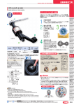
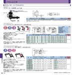
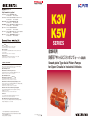
精密機械カンパニー
http://www.khi.co.jp/kpm/
K3V
K5V
東 京 本 社 〒105-8315 東京都港区海岸1丁目14-5
Tel. 03-3435-6862
Fax. 03-3435-2023
神 戸 本 社 〒650-8680 神戸市中央区東川崎町1丁目1-3(神戸クリスタルタワー)
Tel. 078-360-8605
Fax. 078-360-8609
西 神 戸 工 場 〒651-2239 神戸市西区櫨谷町松本234番地
Tel. 078-991-1133
Fax. 078-991-3186
福 岡 営 業 所 〒812-0011 福岡市博多区博多駅前1丁目4-1(博多駅前第一生命ビルディング9F)
Tel. 092-432-9561
Fax. 092-432-9566
東京サービスセンター 〒272-0015 千葉県市川市鬼高4丁目9-2
Tel. 047-379-8181
Fax. 047-379-8186
今治サービスセンター 〒794-0028 愛媛県今治市北宝来町1丁目5-3(ジブラルタ生命ビル、川重商事内)
Tel. 0898-22-2531
Fax. 0898-22-2183
福岡サービスセンター 〒811-0112 福岡県粕屋郡新宮町下府2丁目10-17 Tel. 092-963-0452
Fax. 092-963-2755
SERIES
Precision Machinery Company
Tokyo Head Office
1-14-5 Kaigan, Minato-ku, Tokyo 105-8315, Japan
Phone +81-3-3435-6862 Fax. +81-3-3435-2023
産業車両用
斜板形アキシャルピストンポンプ(オープン回路用)
Kobe Head Office
Kobe Crystal Tower, 1-3 Higashikawasaki-cho 1-chome, Chuo-ku, Kobe
650-8680, Japan
Phone +81-78-360-8607 Fax. +81-78-360-8609
Nishi-kobe Works
234, Matsumoto, Hasetani-cho, Nishi-ku, Kobe 651-2239, Japan
Phone +81-78-991-1160 Fax. +81-78-991-3186
Swash-plate Type Axial Piston Pumps
for Open Circuits in Industrial Vehicles
OVERSEAS SUBSIDIARIES
Kawasaki Precision Machinery (UK) Ltd.
Ernesettle Lane, Ernesettle, Plymouth, Devon, PL5 2SA United Kingdom
Phone +44-1752-364394 Fax. +44-1752-364816
http://www.kpm-eu.com
Kawasaki Precision Machinery (U.S.A.), Inc.
3838 Broadmoor Avenue S.E. Grand Rapids, Michigan 49512, U.S.A.
Phone +1-616-975-3100 Fax. +1-616-975-3103
http://www.kpm-usa.com
Kawasaki Precision Machinery (Suzhou) Ltd.
668 JianLin Rd, New District, Suzhou, 215151 China
Phone +86-512-6616-0365 Fax. +86-512-6616-0366
Kawasaki Precision Machinery Trading (Shanghai) Co., Ltd.
17th Floor (Room 1701), The Headquarters Building, No168, XiZang Road (M),
Huangpu District, Shanghai, 200001, China
Phone +86-021-3366-3800 Fax. +86-021-3366-3808
Kawasaki Chunhui Precision Machinery (Zhejiang) Ltd.
No.200 Yasha Road Shangyu Economic Development Zone, Shansyu,
Zhejiang, 312300, China
Phone +86-575-8215-6999 Fax. +86-575-8215-8699
Flutek, Ltd.
192-11, Shinchon-dong, Changwon, Kyungnam, 641-370, Korea
Phone +82-55-210-5900 Fax. +82-55-286-5557
Wipro Kawasaki Precision Machinery Private Limited
No. 15, Sy. No. 35 & 37, Kumbalgodu Industrial Area, Kumbalgodu Village,
Kengeri Hobli, Bangalore, – 560074, India
このカタログに記載の内容は、改良のため予告なく改訂・変更する場合があります。
Materials and specifications are subject to change without manufacturer's obligation.
このカタログは再生紙を使用しています。
This catalog is printed on recycled paper.
Cat. No. KPM1309 Sep. ’
13 S
Printed in Japan
この製品のご採用、ご使用にあたって
当社の製品は、十分な知識と長年の経験に基づいて設計され、厳しい品質管理の下に製造していますが、
ご採用いただくにあたっては次の点にご配慮くださいますようお願いいたします。
安全上の注意事項
関連法規についての注意
本カタログの製品を安全にご使用いただくために、下記「製品使用についての注意」や、当該製品の取扱説明書を十分にご理解いただく
とともに、以下関連規格の安全に関する法規類を必ず遵守の上、お取扱いください。
[安全に関する関連規格]
このカタログに掲載されている製品は、使用される条件が多様なため、製品のシステムへの適合性の決定は、
油圧システムの設計者または仕様を決定する人が、必要に応じて分析やテストを行なってから判断してください。
また、常に最新のカタログや資料で仕様を検討し、機械の故障の可能性についての状況を考慮してシステムを
構成してください。
(1)製品を取り扱う時の注意事項
製品のご使用にあたっては、安全上の注意事項を遵守の上、正しい使用方法でお使いください。
注意
このカタログに記載された技術情報は、製品の特性や性能を説明する代表値であり、保証値ではありません。
注意
注意
本カタログに掲載された情報は、予告なしに変更される場合があります。最新情報については、当社までお問合せ
ください。
The operating conditions of the products shown in this catalog vary depending upon each application.
Therefore, the decision of the products' suitability to the system considered must be made by the
designer of the hydraulic system and/or the person in charge of determining the specification after
making analysis and conducting tests, if necessary. The study of the specification shall be done based
on the latest catalog and technical documents, and the system must be composed taking into account
situations regarding the possibility of machine failure.
注意
製品の重量、作業姿勢によっては、手を
挟んだり腰を痛めたりすることがあります
ので、作業方法に十分注意してください。
取付穴、
取付面を清浄な状態にしてください。
ボルトの締めつけ不良、
シール破損により、
破
損、
油漏れなどを起こす恐れがあります。
注意
製品を取り付ける時は必ず規定のボルト
を使用し、規定のトルクで締めつけてくだ
さい。規定外の取り付けをすると作動不
良、破損、油漏れを起こすことがあります
ので注意してください。
製品に乗ったり、叩いたり、落としたり、外
力を加えたりしないでください。作動不良、
破損、油漏れなどを起こすことがあります。
製品や床に付着した作動油は十分にふき
取ってください。製品を落としたり、すべっ
てけがをする恐れがあります。
作業を行なう際には必ず装置の電源を切
り、
電動機、
エンジン等が停止したことを確
認してください。
また、油圧配管内の圧力が
「0」圧であることも確認してください。
危険
爆発または燃焼する危険性のある雰囲気
の中では、対策を講じた製品以外は絶対
に使用しないでください。
警告
ポンプやモータなどの回転軸の 保護カ
バーは必ず付けたままとし、手や衣類など
の巻き込みを防止してください。
警告
異常(異音、油漏れ、煙など)が発生した
場合は直ちに運転を停止し、必要な処置
を講じてください。破損、火災、けがなど
の恐れがあります。
注意
初めて装置を運転する場合は油圧回路、
電気
配線が正しいこと、
および締結部に緩みがな
いことを確認した上で運転してください。
注意
製品はカタログ、図面、仕様書などに記載
された仕様以外で使用しないでください。
注意
運転中、製品は油温やソレノイドの温度
上昇などにより高温になりますので、手や
体が触れないように注意してください。や
けどの恐れがあります。
注意
作動油は適正な物を使用し、
汚染度も推奨値
で管理してください。
作動不良、
破損の恐れ
があります。
(4)保守・保管上の注意事項
注意
お客様による製品の改造は、絶対にしな
いでください。
注意
製品は断りなく分解、組み直しをしないで
ください。定められた性能を発揮できず、
故障や事故の原因になります。やむを得ず
分解、組み直しをする場合は専門知識の
ある方が行なってください。
注意
製品を運搬、保管する場合は、周囲温度、
湿度など環境条件に注意し、防塵、防錆
を保ってください。
注意
製品を長期保管後に使用する場合には、
シール類の交換を必要とする場合があり
ます。
SAFETY PRECAUTIONS
Before you use the product, you MUST read the operation or operators manual and MUST fully understand how to use the product.
To use the product safely, you MUST carefully read all Warnings and Cautions in this manual. You MUST also observe the
related regulations and rules regarding safety.
Cautions related to operation
Use the product under the specification
Turn off the power before starting wiring
CAUTION
Use the safety equipment to avoid the
injury when you operate the product.
Pay enough attention on handling method
to avoid pinching hands or back problems
CAUTION that may be caused by heavy weight of
the product or handling posture.
Do not step on the product, hit it, drop it
or give strong outside force to it, as one
CAUTION of these actions may cause the failure of
work, damage or oil leakage.
The technical information in this catalog represents typical characteristics and performance of the
products, and is not guaranteed one.
Wipe the oil on the product or floor off
completely, as the oil creates slippery
CAUTION conditions that may result in dropping the
product or injuring.
The information described in this catalog is subject to change without notice.
For updated information, please consult our campany.
(3)運転時の注意事項
取り付け、取り外し、配管、配線などの作業
は、専門知識のある方が行なってください。
Prior to use of the products, descriptions given in the SAFETY PRECAUTIONS must be observed for the
proper use.
In case the products are used in the following conditions or environments, please consult us prior to the
use.
Unspecified conditions or environments
Use for atomic power, aviation, medical treatment, and/or food
Use likely to affect human beings or assets significantly or requiring particular safety
1
製品を取り扱う際にけがをすることがあり
ますので、状況に応じて保護具を着用して
ください。
電気配線工事は必ず電源を切ってから行
なってください。感電する恐れがあります。
*専門知識のある方:油圧調整技能士2級
程度、
または当社のサービス研修を受け
た方。
警告
Although our products are designed on the basis of our profound knowledge and long experience, and
manufactured under the strict quality control system, the following must be taken into consideration in
actual use.
JIS B 8243 圧力容器の構造
JIS B 8361 油圧システム通則
警告
(2)製品の取り付け、取り外し時の注意事項
注意
ON APPLICATION / USAGE OF THE PRODUCTS
消防法
防爆等級
製品使用についての注意
注意
次に示すような条件や環境でのご使用にあたっては、事前に当社までご相談ください。
① 明記されている仕様以外の条件や環境。
② 原子力、航空、医療、食品などの用途に使われる場合。
③ 人や財産に大きな影響が予想される用途、とくに安全性が要求される用途に使われる場合。
高圧ガス取締法
労働安全衛生法?
Warnings and Cautions related to
installation and removal of the product
CAUTION
Installation, removal, plumbing, and wiring
must be done by the certified person.
* CERTIFIED PERSON: a person who has
enough knowledge like a person who is
trained by Kawasaki’s hydraulic school.
Make it sure that the power of the
hydraulic power unit is turned off and
WARNING that the electric motor or engine has
completely stopped before starting
installation or removal. You must also
check the system pressure has dropped to
zero.
or other works related to the electric
WARNING power, otherwise you may be stuck by an
electric shock.
Clean the threads and mounting surface
completely, otherwise you may
CAUTION experience damages or oil leakage caused
by insufficient tightening torque or
broken seal.
Use the specified bolts and keep the
specified tightening torque when you
CAUTION install the product. Usage of unauthorized
bolts, lack of torque or excess of torque
may create problems such as failure of
work, damage and oil leakage.
Warnings and Cautions for operation
Never use the product not equipped with
anti-explosion protection in the
DANGER circumstances of possible explosion or
combustion.
Shield the rotating part such as motor
shaft and pump shaft to avoid injuries
WARNING caused by being caught of fingers or
cloths.
Stop the operation immediately if you
find something wrong such as unusual
WARNING noise, oil leakage or smoke, and fix it
properly. If you continue operating, you
may encounter damage, fire or injury.
Make it sure that plumbing and wiring are
correct and all the connection is tightened
CAUTION correctly before you start operating,
especially if it is the first run.
CAUTION
mentioned in the catalog, drawings and
specification sheet.
Keep your body off the product during
the operations as it may become hot and
CAUTION burn your body.
CAUTION
Use the proper hydraulic oil, and
maintain the contamination in the
recommended level, otherwise it may not
work or be damaged.
Cautions related to maintenance
CAUTION
Never modify the product without
approval of Kawasaki.
Do not disassemble and assemble
without approval by Kawasaki. It may
CAUTION cause troubles and failure, or it may not
work as specified. If it is necessary by all
means to disassemble and assemble, it
must be done by an authorized person.
Keep the product from dust and rust by
paying attention to the surrounding
CAUTION temperature and humidity when you
transport or store the product.
CAUTION
Replacing the seals may be required if
you use the product after long time
storage.
2
斜板形アキシャルピストンポンプの豊富なバリエーションの中 から、建設機械に最適なオープン回路用ポンプをご紹介します。
Out of a Wide Variety of Our Swash Plate Type Axial Piston Pumps, We Introduce below Those Most Suitable for Construction Machines with Open Circuits.
川崎重工の産業車両用斜板形アキシャルピストンポンプ
徹底した機能設計が、これだけの魅力を生み出しました
Kawasaki Swash Plate Type Axial Piston Pumps Programs for Industrial Vehicles
A Thorough Function Desigh Enabled Such Atractive Features
押しのけ容積
displacement
60 cm3
タンデム形ダブルポンプ
double pump (tandem type)
K3V63DT
/K5V80DT
パラレル形ダブルポンプ
double pump (parallel type)
K3V63DTP
/ K5V80DTP
シングルポンプ
single pump
K3V63S/K5V80S
80
1. 高出力密度
半円筒形の斜板の採用によって、
高圧化と軽量・コンパク
ト化をはかり、
出力密度
(単位質量あたりの出力)
を増加させ
ました。
また、
タンデム形ダブルポンプは、
動力分割用ギヤボッ
クスをなくして伝達効率の向上と軽量化をはかっています。
2. 高効率・高自吸能力
K3V112DT
/K5V140DT
K3V112DTP
/K5V140DTP
110
球面形弁板の採用と油圧バランスの改良により、
安定し
たシリンダの回転姿勢が得られるため、低圧・低傾転域ま
で、
高い効率が得られます。
K3V112DP
K3V112S/K5V140S
3. 長寿命
高負荷容量の主軸受と、
シューの摩耗を補正するピスト
ン・リターンメカニズムの採用により、長寿命化をはかって
います。
K3V140DT
K3V140DTP
K3V140S
140
160
4. 低騒音
ケーシング剛性および弁板設計の改善などによって、
いっそうの低騒音化を実現しました。
K5V160DT
K5V160DTP
5. 豊富な制御方式
K5V160DP
K5V160S
機械・油圧・電気を入力とする各種制御方式が可能です。
1. High Power Density
A lighter and more compact machine with higher
pressure rating and increased power density (output
power/mass) was obtained by adopting a half log type
swash plate.
In particular, the double pump with its tandem
arrangement, has eliminated a power divider, has an
increased transmission efficiency, and is lighter.
2. High Efficiency and Large Self-Priming Capability
The spherical valve plate and improved hydraulic balance
provide stable cylinder rotation, thus achieving high
efficiency even in a low-pressure and low-speed
operating range.
3. Long Life
A long life is obtained by adopting main bearings of large
capacity and the piston-return mechanism that
compensates for the wear of the shoe.
4. Low Noise
Even less noise has been achieved because of the
optimum design of the valve plate and the casing rigidity.
5. Wide Range of Controls
The pump can be controlled in various kinds of control
methods and is capable of responding to either
mechanical, hydraulic or electrical input.
K5V160DTH
200
K5V200DP
K5V200DT
K5V200S
K5V200DTP
K5V200SH
K5V200DTH
K5V200DPH
/ K5V212DPH
K3V280S
280
K3V280DTH
K5V200DPH
/ K5V212DPH
(PTO 付 / with PTO)
K3V280SH
3
4
SERIES
SERIES
K3Vシリーズの信頼性を踏襲するとともに、さらに新技術の適
用によって、高出力密度を達成しています。
K3Vシリーズポンプは、長年の豊富な経験と実績に基づく高出
力密度、高効率、高信頼性を向上、徹底した機能設計を追求し
た建設機械用片傾転専用ピストンポンプです。
With new technology the K5V series has enabled increased
power density.
K3V series pump has optimum functuon design and is
provided with improved power density, efficiency, and reliability,
attained from our many years of experiences.
•K3V/K5V 押しのけ容積バリエーション
Variation of pump displacement
K3V
63
112
140 180
280
K5V
K5V80 K5V140 K5V160 K5V200
0
50
100
150
200
250
300
押しのけ容積 displacement (cm 3)
形式表示 /ORDERING CODE
形式表示 /ORDERING CODE
K3V 280 DT H 100 R
2N 01
K5V 200 DT H 100 R
レギュレータ設計番号
design code of regulator
K3V series
レギュレータコード
regulator code
押しのけ容積
displacement
63 : 63cm3
112 : 112cm3
140 : 140cm3
280 : 280cm3
回転方向
direction of rotation
R : 右回転 clockwise
L : 左回転 counterclockwise
軸端より見て
viewed from shaft end
設計番号
desigh code
DT: タンデム形ダブルポンプ
tandem type double pump
DP: パラレル形ダブルポンプ
parallel type double pump
S : シングルポンプ
single pump
標準 standard
:
インペラー付 with centrifugal pump
H
P : PTO付 with PTO
仕様 /SPECIFICATIONS
1MPa=10.197kgf/cm2
1N·m=0.10197kgf-m
サイズ size
63
押しのけ容積 displacement
(cm )
3
112
63
112
140
圧 力
pressure
(MPa)
1
回転数
speed
(min-1)
2
自吸最高 max. for self priming
2,650
2,360
2,150
3
最 高 max.
3,250
2,700
2,500
定 格 rated
34.3
ピーク
39.2
peak
最大入力トルク(タンデムポンプ) max. input torque of tandem pump
(N·m)
(N·m)
付属ギヤポンプ(PTO部)最大入力トルク
max. input torque of attached gear pump with PTO
質 量
シングル single
mass
タン デム tandem
(kg)
種 類 type
343
588
粘度範囲 oil viscosity range
フィルトレーション filtration
1,120
125
280
280
1,600
(2,000) 4
2,000
1,950
294
48
68
86
140
81
125
160
270
5 耐摩耗性作動油 antiwear
hydraulic fluid
- 20 ~ + 95 °C
温度範囲 oil temperature range
作動油
hydraulic
fluid
5
140
10 ~ 1,000 mm /S (cSt)
2
吸入ライン
suction line
戻りライン
return line
80 ~ 150 mesh
ノミナル 10μm
nominal 10 micron meter
レギュレータ設計番号
design code of regulator
K5V series
押しのけ容積
displacement
80 : 80 cm3
140 : 140 cm3
160 : 160 cm3
200 : 200 cm3
212: 212cm3
DT: タンデム形ダブルポンプ
tandem type double pump
DP: パラレル形ダブルポンプ
parallel type double pump
S : シングルポンプ
single pump
レギュレータコード
regulator code
ー : 標準 standard
H : インペラー付 with centrifugal pump
P : PTO付 with PTO
仕様 /SPECIFICATIONS
2. 傾転角最大の場合の標準ポンプの
限界回転数です。エンジン駆動の
場合にはハイアイドル回転数が
この値以下であることが必要で
す。吸入フランジ部で- 0.01MPa
以上を確認して下さい。
At max. displacement. In case of
engine driving, max. idling speed
should be below this value.
This suction pressure should be
-0.01MPa and above.
3. 吸入フランジ部で 0.1MPa 以上の
ブースト圧が必要です。
Suction pressure should be
above 0.1MPa.
4. ブースター付きの場合
Max. speed with centrifugal pump
5. その他の作動油を使用する場合
は必ずご相談ください。
When other kinds of fluid would
be used, please consult with us.
(cm3)
押しのけ容積 displacement
圧 力
pressure
(MPa)
回転数
speed
(min-1)
1
1MPa=10.197kgf/cm2
1N·m=0.10197kgf-m
80
140
160
200
212
80
140
160
200
214
定 格 rated
34.3
ピーク
39.2
peak
2
自吸最高 max. for self priming
2,460
2,160
3
最 高 max.
3,000
2,500
タンデム tandem
529
843
パラレル parallel
─
─
最大入力トルク
max. input torque
(N·m)
付属ギヤポンプ(PTO部)最大入力トルク タンデム tandem
max. input torque of attached gear pump
パラレル parallel
with PTO (N·m)
質 量
mass
(kg)
回転方向
direction of rotation
R : 右回転 clockwise
L : 左回転 counterclockwise
軸端より見て
viewed from shaft end
設計番号
desigh code
サイズ size
1. 性能、機能、寿命を保証できる圧
力で、強度上問題ありませんが、
軸受寿命には限界があります。
Pressure to which guarantee of
performance, functions or service
life is applied. Durability is unlimited
(except for the bearing life).
9N 01
2,000
1,900
(2,350) 4 (2,200) 4
2,200
2,350
2,000
2,000
─
1,120
1,200
125
1,350
1,500
─
294
─
332
シン グル single
48
68
86
─
タン デム tandem
81
125
160
─
パラレル parallel
─
種 類 type
─
249
5 耐摩耗性作動油 antiwear
温度範囲 oil temperature range
作動油
粘度範囲 oil viscosity range
hydraulic
吸入ライン
fluid
suction line
フィルトレーション filtration
戻りライン
return line
262
hydraulic fluid
- 20 ~ + 95 °C
10 ~ 1,000 mm 2/S (cSt)
80 ~ 150 mesh
272
1. 性能、機能、寿命を保証できる圧
力で、強度上問題ありませんが、
軸受寿命には限界があります。
Pressure to which guarantee of
performance, functions or service
life is applied. Durability is unlimited
(except for the bearing life).
2. 傾転角最大の場合の標準ポンプの
限界回転数です。エンジン駆動の
場合にはハイアイドル回転数がこの
値以下であることが必要です。吸入
フランジ部で- 0.01MPa以上を確認
して下さい。
At max. displacement. In case of
engine driving, max. idling speed
should be below this value.
This suction pressure should be
-0.01MPa and above.
3. 吸入フランジ部で 0.1MPa 以上の
ブースト圧が必要です。
Suction pressure should be
above 0.1MPa.
4. ブースター付きの場合
Max. speed with centrifugal pump
5. その他の作動油を使用する場合
は必ずご相談ください。
When other kinds of fluid would
be used, please consult with us.
ノミナル 10 μm
nominal 10 micron meter
6
レギュレータ一覧/SUMMARY OF REGULATORS
●馬力制御
/Horsepower Control
コード 制御形式
code control type
1
定馬力制御
constant
horsepower
control
●流量制御 /Flow
制御線図
control curve
機能および特長
function & features
コード 制御形式
code control type
自己ポンプ吐出圧力の上昇に
従って、ポンプの傾転角を自
動的に減少させてトルクを一
定に制御できます。
Q
Control
According to the rise of delivery pressuer of a pump, the tilting angle of the
pump is automatically decreased, and
the constant torque control is achieved.
制御線図
control curve
Q
M
レバー流量制御
manual flow control
2
P2 相手ポンプ圧力
companion pump
pressure
Q
P2
P1
With the manual control, the outlet flow
can be steplessly controlled.
パイロット圧力により正流量
制御が行なえます。
Positive flow control can be carried out
by using the pilot pressure.
パイロット圧力により負流量
制御が行なえます。
Negative flow control can be carried
out by using the pilot pressure.
外部からの指令圧力Pmによ
り最大流量を2段階に制御で
きます。
(負流量制御の場合のみ)
Two-stage max. flow control can be
obtained by supplying external pilot
pressure.
(only in negative flow control)
レバーストローク lever stroke
1.自己ポンプ吐出圧力の上昇 1. According to the rise of deliver y
pressure of a pump, the tilting angle
に従って、ポンプの傾転角を
of the pump is automatically de 自動的に減少させてトルク
creased, and the constant torque
を一定に制御できます。
control is achieved. (compensation
control)
2.相手ポンプ圧力により馬力を 2.The total horsepower control can be
減少させ、全馬力制御(相手
achieved by decreasing the horseポンプの所要馬力分を減馬
power of a pump depending upon
力する制御)が行なえます。
the pressure of its companion pump.
P
正流量制御
(ポジティブ)
positive flow control
Q
Pi
外部パイロット圧力 pilot pressure
N
カットオフのみ
pressure cut-off
Q
4
手動指令により吐出流量を無
段階に制御できます。
S
P
全馬力制御
total
horsepower
control
機能および特長
function & features
負流量制御
(ネガティブ)
negative flow control
Q
Pi
P
5
カットオフ制御
high pressure
cut-off
定馬力 + カットオフ
horsepower control
+ pressure cut-off
Q
吐出圧力が設定値以上になる
と自動的にポンプ吐出量が減
少するプレッシャカットオフ制
御が行なえます。
C
If the pressure rises above the set
value, the pump outlet flow is automatically decreased by the pressure
cut-off control.
最大流量2段制御
2-stage max. flow
control
Q
Pm
Pi
P
全馬力 + カットオフ
total
horsepower control
+ pressure cut-off
Q
6
L
ロードセンシング制御
load sensing control
△P=PA-PL
PA : ポンプ圧
pump pressure
Q
△P
P
9
パワーシフト制御
variable
horsepower
control
Q
Pf
外部から電流値またはパイロ Variable horsepower control can be
ット圧力Pfを導入することによ obtained by supplying pilot pressure or
りポンプ入力馬力を無段階に electric current.
制御できます。
E
電気流量制御
electric flow control
Q
I
制御形式
control
type
10
定馬力制御
constant horsepower
control
20
60
2P
全馬力制御 + カットオフ制御
total horsepower control +
high-pressure cut-off
全馬力制御
total horsepower
control
P2
流量制御と馬力制御を組合わせて使用することができます。
上表にレギュレータの回路例を示します。
本表以外の制御をご希望の場合はご相談ください。
7
2N
正流量制御 + 全馬力制御
positive flow control +
total horsepower control
9L
負流量制御 + 全馬力制御
negative flow control +
total horsepower control
P2
回路図
circuit
diagram
P2
Pi1
入力電流に比例させて流量を With the electric current, the oulet flow
増加させる電気流量制御が行 can be controlled.
なえます。
電流値 electric current
P
レギュレータコードNo.
code No.
PL : 負荷圧
load pressure
ポンプ圧と負荷圧の差圧を常 Load sensing control can be obtained.
に一定にさせるロードセンシン
グ制御が行なえます。
P2
Pi1
ロードセンシング制御 +
全馬力制御 + パワーシフト
load sensing control +
total horsepower control +
variable horsepower control
2C
負流量制御 + 全馬力制御 +
最大流量2段制御
negative flow control +
total horsepower control +
two-stage max. flow control
P2
Pf
PL
PA
9N
負流量制御 + 全馬力制御 +
パワーシフト
negative flow control +
total horsepower control +
variable horsepower control
P2
Pm1
Pf
P2
Pi1
Pi1
Flow cotrol and Horsepower control can be combined with
each other.
Examples of applied circuits are shown above.
Please consult us about other kinds of control, if necessary.
8
寸法 /DIMENSIONS
/ Tandem Type
●寸法表
L1
回転方向 direction of rotation
吸 入 suction
吐 出 delivery
L3
Dr1
: 右回転 clockwise
: 左回転 counterclockwise
Dr2
L2
軸端より見て
viewed from shaft end
吸 入 suction
吐 出 delivery
L9
L10
d
PTO部寸法
Dimensions of PTO unit
L22
SAE
L21 M インボリュートスプライン
L19
L18
D3
L20
Dr1
L23
Involute spline
to SAE
Dr2
L2
SAE インボリュートスプライン要目表
Involute spline to SAE
吸 入 suction
L9
歯 数/number of teeth
歯底形状
root form
工具
cutter ダイヤメトラルピッチ
diametral pitch
圧力角/pressure angle
嵌 合
type of fit
規 格/rule
10
L2
70
80
92
150
70
80
92
92
L3
70
80
92
125
70
80
92
92
L4
142
142
142
142
142
142
142
142
L18
177
214
257
177
214
257
257
L19
268
305
361
268
305
361
361
L20
L21
2.4
2.4
2.4
2.4
2.4
2.4
2.4
L22
8
8
15
8
8
15
15
L23
M
150
150
200
150
150
200
200
106
106
127
106
106
127
127
2—M10—25
2—M10—25
4—M12—22
2—M10—25
2—M10—25
4—M12—22
4—M12—22
要 目 spec.
/
● 吸入フランジ取付面(SAE規格)Flange
サイズ size
K3V63
K3V112
K3V140
K3V280
K5V80
K5V140
K5V160
K5V200
a
50.8
50.8
61.9
69.8
50.8
50.8
61.9
61.9
/
16 /32
30°
サイドフィ
ット
side fit
SAE
L15
L7
サイズ size
K3V63
K3V112
K3V140
K3V280
K5V80
K5V140
K5V160
K5V200
a
23.8
23.8
27.8
31.8
23.8
27.8
27.8
27.8
b
50.8
50.8
57.2
66.7
50.8
57.2
57.2
57.2
c
19
19
25
32
19
25
25
25
Dr2
Dr1
L16
L6
30°
/
L11 L12
L6
89
100
112
127
89
100
112
112
L7
98
110
123
140
98
110
123
123
L8
8
8
8
8
8
8
8
8
L9
228
265
305
356
228
265
305
305
L10
138
167
190
203
138
167
190
190
L11
37
41
53
70
37
41
53
53
L12
37
41
53
70
37
41
53
53
L13
464
538
618
792
464
538
618
618
L14
97
109
121
150
97
109
121
121
L15
195
220
245
286
195
220
245
245
D1
L5
L13
フランジ取付面
flange mounting face
吐 出 delivery
L17
フランジ取付面
flange mounting face
サイズ size
K3V63
K3V112
K3V140
K3V280
K5V80
K5V140
K5V160
K5V200
a
G 1/2
G 3/4
G 3/4
G 3/4
G 1/2
G 3/4
G 3/4
G 3/4
b
22.6
30.8
30.8
30.8
22.6
30.8
30.8
30.8
モジュールまたは
ダイヤメトラルピッチ
module
圧力角
pressure angle
30°
20°
規 格
rule
SAE
JIS B 1603
JIS B 1603
JIS B 1603
JIS B 1603
JIS B 1603
JIS B 1603
JIS B 1603
12 / 24
2.5
2.5
3.0
2.5
2.5
2.5
2.5
20°
20°
20°
20°
20°
20°
mounting face for Suction port ( SAE Rule )
(mm)
c
60
60
76
89
60
60
76
76
b
88.9
88.9
106.4
120.7
88.9
88.9
106.4
106.4
● 外部ドレンポート
(JIS B 2351規格)Drain
D2
L5
190
234
256
300
190
234
256
256
ピッチ円直径 (mm)
pitch circle dia
29.6
35.0
42.5
54.0
30.0
42.5
42.5
42.5
歯 数
no. of teeth
14
14
17
18
12
17
17
17
●吐出フランジ取付面
(SAE規格)Flange
13
フラットルート
flat root
L10
4- d
9
82.55
82.55
101.6
101.6
18
22
22
26
18
22
22
22
L1
76
78
93
115
76
78
93
93
d—ネジ深さ depth
M12—18
M12—18
M16—24
M16—24
M12—18
M12—18
M16—24
M16—24
L9
d
c
b
mounting face for Delivery port (SAE Rule)
(mm)
d
31.0
31.0
37.5
61.5
31.0
37.5
37.5
37.5
e—ネジ深さ depth
M10—16
M10—16
M12—22
M12—20
M10—16
M12—22
M12—22
M12—22
d
d
c
e
c
a
L9
a
port (Rule: JIS B 2351)
(mm)
c
2.5
3.5
3.5
3.5
2.5
3.5
3.5
3.5
d
19
20
23
23
19
20
23
23
15°
b
c
PTO 付)/ Tandem Type (with PTO)
L8
L17
213
213
292
213
213
292
292
d
a
d
フランジ取付面
flange mounting face
L4
L16
110
110
122
110
110
122
122
(mm)
D3
82.55
82.55
101.6
K3V63
K3V112
K3V140
K3V280
K5V80
K5V140
K5V160
K5V200
L13
ドレンポートはDr1,Dr 2の1ヵ所を使用
Use Dr1 or Dr2 port for case drain.
サイズ size
K3V63
K3V112
K3V140
K5V80
K5V140
K5V160
K5V200
サイズ size
L14
L5
L1
D2
125
160
180
200
125
160
180
180
/Dimensions of shaft end
Dr2
Dr1
D1
●タンデム形
(
D1
180
224
250
300
180
224
250
250
● 軸端スプライン要目
L6
D2
30°
L11 L12
L7
L15
4-
L8
サイズ size
K3V63
K3V112
K3V140
K3V280
K5V80
K5V140
K5V160
K5V200
a
ドレンポートはDr1,Dr 2の1ヵ所を使用
Use Dr1 or Dr2 port for case drain.
L4
/Dimensions
b
●タンデム形
45°
10
寸法 /DIMENSIONS
/Parallel Type
●シングル形
L4
D2
ドレンポートはDr1の1ヵ所を使用
Use Dr1 port for case drain.
47
L6
回転方向 : 右回転
direction of rotation: clockwise
12 d
軸端より見て
viewed from shaft end
L3
L8
L9
L10
L4
15°
°
L15
4- d
L11 L12
D1
D1
°
°
164
PTO 付
with PTO
143
160
/Dimensions
サイズ size
K3V112
K5V160
K5V200
K5V212
D1
D2
429
530
530
530
410
511
511
511
d
11
14
14
14
L1
L2
L3
L4
L5
L6
L7
L8
L9
L10
L11
L12
L13
235
272
272
272
113
135
135
135
163
206
206
206
111
141
141
141
256
301
301
301
428
456
492
495
493
519
570
573
34
36
52
69
5
5
5
5
148
135
135
138
522
549
600
603
391
422
400
403
385
398
398
401
/Dimensions of shaft end
● 軸端スプライン要目
サイズ size
要 目 spec.
K3V112
K5V160
K5V200
K5V212
歯 数
no. of teeth
ピッチ円直径 (mm)
pitch circle dia
圧力角
pressure angle
モジュールまたは
ダイヤメトラルピッチ
module
規 格
rule
14
15
15
15
35.0
47.6
47.6
47.6
20°
30°
30°
30°
2.5
8/16
8/16
8/16
JIS B 1603
ANSI
ANSI
ANSI
● 吸入フランジ取付面(SAE規格)
c
60
102
76
76
b
88.9
130.2
120.7
120.7
d—ネジ深さ depth
M12—18
M16—24
M16—24
M16—24
c
50.8
66.7
66.7
66.7
19
32
32
32
d
e—ネジ深さ depth
34.0
41.5
41.5
41.5
M10—16
M12—22
M12—22
M12—22
11
c
a
c
3.5
3.5
3.5
3.5
d
20
23
23
23
L3
L4
L5
L6
L7
L8
L9
L10
L11
L12
L13
L14
L15
L16
76
78
93
115
76
78
93
75
70
80
92
150
70
92
92
92
70
80
92
125
70
92
92
92
142
142
142
142
142
142
142
142
190
234
256
300
190
234
256
262
89
100
112
127
89
100
112
131
98
110
123
140
98
110
123
131
8
8
8
8
8
8
8
16
210
250
292
343
210
257
292
300
138
167
190
203
138
167
190
190
37
41
53
70
37
41
53
53
37
41
53
70
37
41
53
53
277
309
366
433
277
326
366
389
89
109
121
135
89
110
121
121
195
220
245
286
195
220
245
245
225
/Dimensions of shaft end
● 軸端スプライン要目
要 目 spec.
サイズ size
K3V63
K3V112
K3V140
K3V280
K5V80
K5V140
K5V160
K5V200
歯 数
no. of teeth
ピッチ円直径 (mm)
pitch circle dia
圧力角
pressure angle
モジュールまたは
ダイヤメトラルピッチ
規 格
module
rule
29.6
35.0
42.5
54.0
30.0
42.5
42.5
41.3
30°
20°
20°
20°
20°
20°
20°
30°
12/24
2.5
2.5
3.0
2.5
2.5
2.5
8/16
SAE
JIS B 1603
JIS B 1603
JIS B 1603
JIS B 1603
JIS B 1603
JIS B 1603
SAE
14
14
17
18
12
17
17
13
a
45˚
K3V63
K3V112
K3V140
K3V280
K5V80
K5V140
K5V160
K5V200
a
23.8
23.8
31.8
31.8
27.8
27.8
36.5
36.5
b
50.8
50.8
66.7
66.7
57.2
57.2
79.4
79.4
c d—ネジ深さ depth
19
M10—16
19
M10—16
32
M12—18
32
M12—20
25
M12—16
25
M12—16
38
M16—24
38
M16—24
● 吸入フランジ取付面(SAE規格)
Flange mounting face for Suction port (SAE Rule)
K3V63
K3V112
K3V140
K3V280
K5V80
K5V140
K5V160
K5V200
G 1/2
G 3/4
G 3/4
G 3/4
G 1/2
G 3/4
G 3/4
G 3/4
22.6
30.8
30.8
30.8
22.6
30.8
30.8
30.8
2.5
3.5
3.5
3.5
2.5
3.5
3.5
3.5
19
20
23
23
19
20
23
23
(mm)
b
d
c
L9
/
b
(mm)
b
30.8
30.8
30.8
30.8
L2
● 外部ドレンポート
(JIS B 2351規格)Drain
(mm)
a
b
c
d
サイズ size
a
c
a
G 3/4
G 3/4
G 3/4
G 3/4
d
c
15˚
Drain port (Rule: JIS B 2351)
K3V112
K5V160
K5V200
K5V212
e
(mm)
● 外部ドレンポート
(JIS B 2351規格)
サイズ size
125
160
180
200
125
160
180
165
サイズ size
d
23.8
31.8
31.8
31.8
c
180
224
250
300
180
224
250
L1
●吐出フランジ取付面
(SAE規格)
b
b
K3V112
K5V160
K5V200
K5V212
b
K3V63
K3V112
K3V140
K3V280
K5V80
K5V140
K5V160
K5V200
(mm)
d
18
22
22
22
18
22
22
21
(mm)
d
Flange mounting face for Delivery port (SAE Rule)
a
D2
Flange mounting face for Delivery port (SAE Rule)
●吐出フランジ取付面
(SAE規格)
サイズ size
D1
(mm)
a
K3V112
K5V160
K5V200
K5V212
a
50.8
77.8
69.9
69.9
/Dimensions
サイズ size
d
Flange mounting face for Suction port (SAE Rule)
サイズ size
● 寸法表
ドレンポートはDr1,Dr 2の1ヵ所を使用
Use Dr1 or Dr2 port for case drain.
サイズ size
K3V63
K3V112
K3V140
K3V280
K5V80
K5V140
K5V160
K5V200
a
30.2
30.2
50.8
69.9
35.7
61.9
61.9
61.9
b
58.7
58.7
88.9
120.7
69.9
106.4
106.4
106.4
c d—ネジ深さ depth
32
M12—18
38
M12—18
60
M12—18
80
M12—20
38
M12—18
76
M16—24
76
M16—24
76
M16—24
L9
d
c
b
port (Rule: JIS B 2351)
15°
b
c
● 寸法表
360
L13
a
d
L12
a
4=
7
12
0)
( 21
146
90
8-M12 ネジ深サ22
thread depth 22
吸 入 suction
フランジ取付面
flange mounting face
L5
Dr2
Dr1
L14
L2
L6
45°
a
(127.3)
L1
L16
L5
30°
L3
吐 出 delivery
30
吸 入 suction
Dr2
D2
L13
軸端より見て
viewed from shaft end
吐 出 delivery
272
L8
: 右回転 clockwise
: 左回転 counterclockwise
L2
ANSI
インボリュートスプライン
Involute spline
to ANSI
19
回転方向 direction of rotation
L7
+0.05
φ101.6+0.03
L5
2.4
吐 出 delivery
Dr1
L6
13
吸 入 suction
L1
4- d
L16
Dr1
φ110
L10
L4
K5V200Sの場合
for K5V200S
PTO部寸法
Dimensions of PTO unit
+0.127
L9
/Single Type
L7
L11
L7
φ22.276 0
●パラレル形
45°
12
取扱い上の注意
CAUTION FOR INSTALLATION
取付方向と外部ドレンの配管
駆動軸との結合
Mounting Direction and Drain Piping
Connection of Driving Shaft
軸を水平にして取付けてください。
外部ドレン用配管を設置し、配管はポンプより一度上に上
げてからタンクに戻してください。
外部ドレンは上部のドレンポートから取ってください。
ドレン配管は、ドレンポートサイズ以上の口径のものを使用
してください。
インペラー付タンデムポンプの場合は、2つのポンプのそれ
ぞれから外部ドレンを取ってください。
The pump shaft should be mounted in the horizontal
direction as shown in the figure below.
The drain line loop must be extended above the top of
the pump case.
The upper drain port should be used, and the drain
pipe size must be equal to or larger than the drain port
size.
In case of the pumps with centrifugal pump, the drain
lines must be settled on each pump.
駆動軸と原動機との結合には、フレキシブルカップリングを
使用してください。
センタリングは、軸心のずれが0.03 mm以内になるように
取付けてください。
軸端にはラジアル荷重やスラスト荷重がかからないようにし
てください。
Please use a flexible coupling for connection of the
pump drive shaft with an engine flywheel or an electric
motor shaft.
Alignment should be so carried out that the parallel
error may be held with in ± 0.03 mm.
Do not put a radial or thrust load at the shaft end.
運転時の注意事項
Starting
始動の際には必ず、ポンプケーシング内にドレンポートから
作動油を満たしてください。作動油がない場合、潤滑不足
のために内部部品が焼き付くおそれがあります。
フロントポンプ
front pump
リヤポンプ
rear pump
タンデムポンプ
tandem pump
ケーシング内圧
Case Drain pressure
ケーシング内圧は、常用で 0.1 MPa 以下、ピーク時でも
0.4 MPa 以下になるようにドレン配管サイズとフィルタサ
イズを選定してください。
フィルタ
Filtration
ポンプの寿命はコンタミネー
ションに大きく影響されます。
タンク内の作動油はNAS9級
(ISO4406-/18/15)以内の清
浄度を保つようにしてください。
アクチュエータの戻り回路に
For satisfactory service life
of these pumps in
application, the operating
fluid should be continuously
fiitered to keep at least the
cleanliness level of NAS 1638
Class 9. (ISO 4406-/18/15)
10μmフィルタを設置してくだ
さい。また、吸入側には80∼
150メッシュのストレーナを設
A 10 µm filter must be used
in the return line and a 80 ~
150 mesh strainer in the
suction lines.
置してください。
フィルタ設置例
Examples of using a filter
空気
air
150メッシュ
150 mesh
13
10 µm
10 µm
Before starting-up, fill the pump case with system fluid
through the case drain connection. Case must remain
full of fluid to provide internal lubrication.
Please be careful so that the drain pressure in the
casing does not exceed 0.1 MPa normally and 0.4
MPa at its peak.
A suitable size of drain hose and drain filter should be
selected.
0.4 MPa (peak)
P
0.1 sec
0.1MPa (normal)
150メッシュ
150 mesh
14