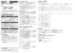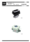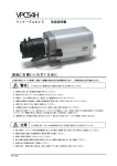
1
ENGLISH ON THE BACK
自動絞り付き電動ズームレンズ 取扱説明書
■ 品名
1/2 型 Cマウントタイプ
H20ZAME-□FH
H15ZAME-□F
H6ZBME-□F
H20ZAME-□FK
H15ZAME-□FH
H18ZME-□F
H10ZME-□F
1/3 型 CSマウントタイプ
TS20ZAME-□F
TS15ZAME-□FH
品名の□には、モータ仕様の1,2,3,5が入ります。詳しくは本文をご覧ください。
このたびはPENTAX CCTVレンズをお買上げいただきありがとうござ
います。ご使用の前にこの取扱説明書を必ずお読みいただき、正しくお使いく
ださい。お読みになった後は、いつでも見られるところに保管してください。
■ レンズを安全にお使いいただくために
この製品の安全性については十分注意を払っておりますが、下記マー
クの内容については特に注意をしてお使いください。
警告
注意
この表示の欄は、「使用者が重大
な障害を受ける可能性があるこ
とを示す」内容です。
この表示の欄は、「使用者が軽傷
または中程度の障害を受けたり、
物的損害の可能性があることを
示す」内容です。
は、禁止事項を表すマークです。
は、注意を促すためのマークです。
警告
レンズ単体を通し、目で直接太陽を見ないでください。
失明の原因になります。
本製品を分解したリ、修理、改造しないでください。
火災、感電、故障の原因になります。
万一、煙が出る、臭いがする、あるいは発熱している場合、
そのまま使用すると火災、感電の原因になります。
接続ケーブルを傷付けたり、無理に曲げたり、ねじったり、引っ
張ったりしないでください。火災、感電、故障の原因になります。
注意
レンズをカメラから外した状態で、直接日光の当たる場所
に置かないでください。火災の原因になることがあります。
レンズの取付けはしっかりと締め付けてください。
締め付けが緩むと、落下してけがの原因になることがあります。
振動や衝撃のある場所に設置しないでください。締め付け
が緩むと、落下してけがの原因になることがあります。
■ 取扱い上のご注意
• レンズボディの汚れを落とすために、シンナーやアルコール、ベン
ジンなどの有機溶剤を使用しないでください。
• レンズ面に付いたゴミや汚れは、ブロワーやきれいなレンズブラシ
で取り除いてください。指紋や油がついたときは、市販のレンズク
リーニングペーパーにレンズクリーニング液をしみ込ませ、レンズ
中心部から周辺部に向け渦巻状に軽く拭き取ってください。
• 接続ケーブルは、「ケーブルの接続」をご覧になり正しく接続して
ください。
• レンズは精密光学機器です。落下・強い振動・衝撃・圧力などを加
えないでください。
• ホコリ・有害ガス・水分・塩分などがかからないようにしてくださ
い。故障の原因になります。
■ マウント
取付け前にカメラのマウントをご確認ください。CSマウントカメラに
Cマウントレンズを使用する場合には、Cマウントアダプターが必要で
す。CSマウントレンズはCマウントカメラにはご使用になれません。
カメラによってはCマウント、CSマウントの切換えが可能なものも
ありますので、カメラの取扱説明書をご覧ください。
カメラマウント
Cマウントレンズ
CSマウントレンズ
Cマウント
使用可
使用不可
CSマウント
Cマウントアダプター使用
使用可
■ ケーブルの接続
❖ D/A付きタイプ(オプション)
❖ 自動絞り用ケーブル
自動絞り用ケーブルをカメラのレンズコネクターに接続します。
このレンズはビデオアイリス方式の自動絞りですので、カメラの自動
絞り方式がビデオアイリス方式であることをご確認ください。
注)アイリスをマニュアルリモートのみ使用する場合にも自動絞りケーブル
の電源供給は必要です。
電動用ケーブルの紫線に下記接続を追加することにより、自動絞りと
マニュアルリモートを切換えます。ズーム,フォーカスと同様の制御
方法で操作します。
• SW1で紫線を黒線(グランド)
に接続すると、マニュアルリモー
トになります。また切り離すと自
動絞りになります。
• マニュアルリモートで合わせた絞
り位置は、カメラの電源を切って
も電源再投入時に元の絞り位置に
復帰します。
標準仕様(アイリス用コネクター無し)
リード線色
赤
白
黒
緑
シールド
仕様
供給電源
画像信号
グランド
――――
ボディアース
カメラの取扱説明書をご覧になり
コネクターを接続してください。
シールドはコネクターに接続せ
ず、ケーブル外被の元でお切りく
ださい。
なお緑線は使用していません。
ケーブル外被の元でお切りくださ
い。
JEITA ※ 規格準拠・4Pコネクター付き
ピン番号
1 2 3 4 EIAJ RC-5204規格準拠コネク
ター付き。
線色・仕様
赤・供給電源
――――
白・画像信号
黒・グランド
※
社団法人電子情報技術産業協会
❖ 電動用ケーブルの接続
付属のコネクターを使用し、レンズコントローラなどの制御機器に接
続してください。モータ仕様は1,2,3,5型があり、電源仕様、
接続が異なります。モータ仕様は、型名のハイフン後の数字で分けて
います。接続仕様については、「電動用ケーブル接続仕様」及び「主
な仕様」をご覧ください。
P E N T A X イ メ ージ ング ・ システム事業部 セキ ュ リ テ ィ ー営業部
Tel.03-3960-0336 Fax.03-3960-0337
3160835-Z2-1 (J) S3095082
マークについて
本体側面にCEマーク表示のあるレンズは、EU(欧州連合)における
EMC指令に関する規格EN50130-4およびEN55022に適合しています。
■ アフターサービス
修理についてはお買い上げの販売店にご相談ください。
■ 商品構成
・レンズ本体 ・前キャップ ・後キャップ
・接続用コネクター ・取扱説明書
■ ポテンショメータ出力
ポテンショメータに電源を供給することにより、ズーム,フォーカス
の位置電圧を出力します。
■ バックフォーカスの合わせ方
フランジバックはCマウント又はCSマウントに調整していますが、
ズーミング時にピントがボケる場合は、カメラの取扱説明書をご覧に
なり下記の手順でカメラのバックフォーカスを調整してください。
① レンズの絞りが開放になるように次の方法で入射光量を調整します。
・ カメラの電子シャッターを高速シャッターにする
・ 市販のNDフィルターでレンズ前面を覆う
② なるべく遠い被写体を写してください(10m以上推奨)。
③ フォーカスを無限端に、ズームを広角端にし、カメラのバック
フォーカスを調整しピントを合わせます。
④ ズームを望遠端にし、レンズ側のフォーカスによりピントを合わ
せます(④、③の順でも調整可能です)。
⑤ ズーム全域でピントが合うように③、④(または④、③)を繰り
返します。
■ 電動用ケーブル接続仕様
■ 調整
❖ ALC調整
自動絞りの測光方式を平均測光(Av)から、ピーク測光(Pk)ま
で連続的に調整することができます。出荷時には平均測光(Av)側
になっていますが、モニター画面のコントラストが高すぎる、あるい
は低すぎると感じる場合には、下表にしたがって調整してください。
モニター画面
ボリューム回転方向
コントラストを低くしたい場合
時計方向(Pk側)
コントラストを高くしたい場合
反時計方向(Av側)
注)回しすぎると、画質が低下する場合があります。
注)カメラの逆光補正,AGC機能により、ALC調整が働かない場合があり
ます。
❖ LEVEL調整
取付けるカメラに合わせ感度を調整することができます。モニター画
面が暗すぎる、映像が出ない、あるいは明るすぎるときは下表にした
がって調整してください。
モニター画面
ボリューム回転方向
画面を明るくする(レベルを高くする)
時計方向(H側)
画面を暗くする(レベルを低くする)
反時計方向(L側)
注)回しすぎると、画質低下や作動に支障をきたすことがあります。
注)被写体が十分に明るい状態で調整してください。正しい調整ができない
場合があります。
注)カメラの逆光補正、AGC機能によりレベルを低くできない場合があり
ます。
注)カメラのAGCが働いている場合L側に回してもレベルが変化せずに、画質
が悪くなることがあります。画質が良くなるまでH側にもどしてください。
■ マニュアルリモート操作
❖ D/A無しタイプ(標準仕様)
電動用ケーブルの茶線に下記の接続を追加することにより、絞りをリ
モートコントロールすることが可能です。
茶線に加える電圧(DC1.5V~5.5V)を変化させ絞りを操作します。
• Vccは制御機器側の供給電圧を表
します。
• SW1で茶線を接続するとマニア
ルリモートに、また茶線を切り離
すか、グランドに接続すると自動
絞りになります。
■ 主な仕様
タイプ
アイリス
マニュアルリ
モート
H O Y A 株式会社
東京都板橋区前野町2丁目36番9号 〒174-8639
■
モータ駆動電
圧
作動温度範囲
供給電源
入力信号
感度調整
絞り精度
1型
2型
3型
5型
1型
2型
3型
5型
DAコンバーター無し(標準)
DC8V~15V 45mA以下
DAコンバーター付き(オプション)
DC8V~15V 50mA以下
VまたはVS信号
V信号レベルで0.5V(p-p)~1.0V(p-p)
V信号レベルで±20%
DC3V~6V 5mA以下/モータ
DC1.5V(絞り込み位置)~5.5V(開放絞り位置)
DC±6V~±12V 5mA以下/モータ
0.3mA以下
DC±3V~±6V 5mA以下/モータ
連続可変
DC6V~12V 5mA以下/モータ
DC3V~6V
DC±6V~±12V
DC±3V~±6V
DC6V~12V
-10℃~+50℃
■ Cable connections
Auto-Iris Motorized Zoom Lens Operating Instructions
■ Model number
1/2 format C mount type
H20ZAME-□FH
H15ZAME-□F
H6ZBME-□F
H20ZAME-□FK
H15ZAME-□FH
H18ZME-□F
H10ZME-□F
1/3 format CS mount type TS20ZAME-□F
TS15ZAME-□FH
□ denotes Type 1,2,3 & 5 representing motor specs and wiring. Refer to this text for
details.
Thank you for choosing PENTAX CCTV lenses. Before operating this
lens, please read these instructions carefully. After reading this
Operating Instructions, keep it for future reference.
■ For your safety on use of a lens
Before operating, pay special attention to the following remarks.
WARNING
CAUTION
This alerts users to the possible
risk of personal harm.
This alerts users to the possible risk
of personal and material harm.
This is a warning to users.
This is to caution users.
WARNING
Do not look at the sun through the lens with the naked eye.
Loss of eyesight may occur.
Do not disassemble, repair or modify the lens.
Fire, electric shocks or malfunction may occur.
If the lens emits smoke, smells of smoke or gives off heat,
discontinue use immediately. Fire or electric shocks may occur.
Do not damage, bend, twist or pull on the cable. Fire, electric
shocks or malfunction may occur.
CAUTION
Do not leave unused lenses in direct sunlight. Fire may occur.
Mount the lens firmly on a camera, so that it will not loosen
and fall off.
Do not install the lens in a place where vibration and shock
are expected. It may come loose and fall off.
■ Precautions
• Do not use organic solvents, such as thinners, alcohol or benzine to
remove stains from the lens.
• Use a blower or a clean lens brush to remove dust. When grease or
fingerprints are on the lens, wipe them off with a lens cleaning paper
and lens cleaner gently forming a swirl from the center to the
circumference.
• Connect the cable properly referring to the following list entitled
"Cable Connections".
• This lens is a precision optical product. Avoid dropping, strong
vibration, shock and pressure on it.
• Keep the lens away from dust, poisonous gas, moisture and salt. It
may cause lens malfunction.
■ Mount
Before mounting the lens, confirm the camera mount matches the lens.
When using a C mount lens on a CS mount camera, a mount adapter
is needed. A CS mount lens cannot be used on a C mount camera.
Camera mount
C mount lenses
CS mount lenses
C mount
Compatible
Not compatible
CS mount
Compatible with a mount adapter
Compatible
HOYA CORPORATION
PENTAX Imaging Systems Division
Security Systems Sales Department
2-36-9, Maeno-cho, Itabashi-ku, Tokyo 174-8639, Japan
Phone +81-3-3960-0347 Fax. +81-3-3960-0337
3160835-Z2-1 (E) S3095082
❖ Special model (with D/A converter)
❖ Auto-iris cable
Installation of the auto iris connector.
This is a video iris lens. Ensure your camera is compatible.
Please Note:
• Power needs to be supplied to the lens through the auto iris cable even if the
lens is constantly used in the manual override iris mode only.
Manual control of the iris can be achieved by connecting the violet wire in the
motor drive cable (illustrated below). The Iris position is altered by using the iris
open/close buttons of a standard lens controller for motorized iris.
• When SW1 is closed, the iris is in
manual override mode.
• When SW1 is open, the iris is in
auto iris mode.
• The manual override iris position
remains in the memory even after a
power failure.
Standard model without auto-iris connector
Wire color
Red
White
Black
Green
Shield
Specifications
Power supply
Video signal
Ground
――――
Grounded to lens
Refer to Operating Instructions of the
camera and install the connector.
Do not connect the shield wires. Cut
them at the base of the auto-iris cable
sheath.
The green wire is not used. Cut it off
at the base of the auto-iris cable
sheath.
With 4-pin connector model conforming to JEITA
Pin No.
1
2
3
4
Color/Specifications This pin configuration is
Red/Power supply conforming to JEITA*.
――――
White/Video signal
Black/Ground
* Japan Electronics and Information
Technology Industries Association
❖ Motor drive cable
Connect to a lens controller by means of the attached connector. Connectors
vary according to lens model and type (1, 2, 3 & 5) distinguished by the number
after the hyphen, denoting different wiring and operating voltages. For details,
refer to “Wiring diagram for motor drive cable” and “Main specifications”.
■
marking
The lenses having CE marking on their bodies are conformity with the
standards EN50130-4 and EN55022 related to EMC directives by EU.
■ After-sales servicing
Contact your supplier for after-sales servicing.
■ Composition
・Lens body
・Female connector
・Front cap
・Rear cap
・Operating instructions
■ Output from potentiometer
By inputting power to potentiometers, they output position voltage.
■ Adjusting back focus
The flange back of the lens is factory adjusted for C mount or CS
mount, respectively. In case images defocus during zooming
operation, perform the following back focus adjustment referring to the
Operating Instructions of the camera.
① Fully open the iris by either of the following methods.
・ Set the auto electronic shutter of the camera to On.
・ Cover front of the lens with a ND filter according to the prevailing
lighting conditions. The brighter the lighting conditions, a higher
ND factor is required.
② Observe an image of a distant object. (Over 10m is recommended.)
③ Set the focus ring at [INFINITY] position and the zoom ring at
[WIDE] position, and then adjust back focus of the camera.
④ Set the zoom ring at [TELE] position and make focus adjust by the focus ring.
⑤ Repeat the procedures ③ and ④ until images maintain their focus
throughout the zoom range.
■ Wiring diagram for motor drive cable
■ Adjustments
❖ ALC adjustment
Metering method of the auto-iris can be linearly adjusted from average
metering to peak metering (Pk). It is factory set at (Av) position. In case
contrast of the image is too high or low, make adjustment according to
the following table.
Images
ALC adjustment direction
To make contrast lower
Clockwise to (Pk)
To make contrast higher
Counter-clockwise to (Av)
Please Note:
• Adjustment by excessive amount may deteriorate image quality.
• ALC may not function due to backlight compensation and AGC of the camera
or cameras with a digital video output.
❖ Level adjustment
Auto-iris sensitivity can be adjusted in accord with the camera. When
images are too dark, too bright or there is no image, make the
adjustment according to the following table.
Images
LEVEL adjustment direction
To brighten the image (raise level)
Clockwise to (H)
To darken the image (lower level)
Counter-clockwise to (L)
Please Note:
• Adjustment by excessive amount may deteriorate image quality or cause
malfunction of the iris.
• Make the adjustment over high contrast objects for the best result.
• LEVEL may not be lowered in some cases due to backlight compensation and
AGC features of the camera being switched on.
• When the AGC of the camera is switched on, there are some instances where
the level does not alter and the image quality deteriorates, even when the
“LEVEL” adjustment variable resistor is turned all the way to “L” side. Turn the
“LEVEL” variable resistor towards “H” until the image quality improves.
■ Manual override iris control
❖ Standard model (without D/A converter)
Manual control of the iris can be achieved by applying a voltage of
between DC1.5V to 5.5V to the brown wire (illustrated below).
• Vcc is power from a controller.
• When SW1 is closed, the iris is in
manual override mode.
• When SW1 is open, the iris is in
auto iris mode.
■ Main specifications
Model
Power supply
Video signal
Iris
Sensitivity adjustment
Iris accuracy
Type 1
Type 2
Manual override iris
Type 3
Type 5
Type 1
Operation voltage of
Type 2
zoom and focus
Type 3
motors
Type 5
Operating temperature range
Without D/A converter (Standard model)
DC8V - 15V less 45mA
With D/A converter (Special model)
DC8V - 15V less 50mA
V or VS
0.5V(p-p) - 1.0V(p-p) at V signal level
±20% at V signal level
DC 3V - 6V less 5mA
DC ±6V - ±12V less 5mA
DC ±3V - ±6V less 5mA
DC 6V - 12V less 5mA
DC1.5V (iris close) - 5.5V (iris open)
Less 0.3mA
continuously adjustable
DC 3V - 6V
DC ±6V - ±12V
DC ±3V - ±6V
DC 6V - 12V
-10℃ - +50℃