1
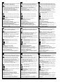
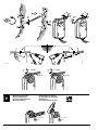
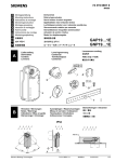
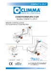
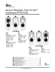
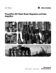
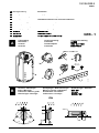
74 319 0332 0 M4621 de en fr sv nl it fi es da Montageanleitung Mounting instructions Instructions de montage Monteringsinstruktion Montage-aanwijzing Istruzioni di montaggio Asennusohje Instrucciones de montaje Monteringsvejledning Drehantrieb Rotary-type actuator Servo-moteur à action angulaire Spjällställdon med vridande rörelse Luchtklepservomotor voor roterende aandrijving Servocomando rotativo per serrande Kiertoliikkeinen ilmapeltien toimimoottori Actuador de acción rotativa Motor for drejebevægelse zh 安装指导 旋转型执行器 ko 설치 지침서 ja 取扱説明書 로터리타입 조작기 ロータリー式ダンパーアクチュエータ A Lieferumfang Delivrables Contenu Leverans GEB...1 Leverancens omfang Leveringsomvang Contenuto Toimituslaajuus Contenido 设备构件 제품의 공급 (구성품) 製品及び付属品 GEB...4.1 / GEB...6.1 j d 90° b 4.8 x 13 DIN 7981 g a c f B Hinweise / Warnungen Notes / Warnings Indications / Mise en garde Hänvisningar / Varningar Aanwijzingen / Waarschuwingen Messa in servizio / Indicazioni Huomauksia / Varoituksia Indicaciones / Consejos 4621Z40 e Bemærkninger / Advarsler 提示 / 警告 주의 사항 保護等級/注意 IP54 <4 5° M4621 5° <4 4621Z02 ASK75.3 ° 90 74 319 0332 0 c 14.09.2012 1/10 de sv fi Diese Anleitung ist beim Antrieb oder in der Anlagendokumentation aufzubewahren! Denna instruktion skall förvaras tillsammans med ställdonet eller anläggningsdokumentationen! Tätä ohjetta tulee säilyttää toimimoottorin läheisyydessä tai yhdessä laitosdokumenttien kanssa! Dieses Symbol weist auf Gefahren und Masnahmen zum Schutz von Personen und Sachen hin: • Antriebe für AC 230 V dürfen nur durch autorisiertes Personal angeschlossen werden. • Zulässige Spannungen an den Hilfsschaltern: Siehe Tabelle unter "Geräteschaltpläne". • Die Anschlusskabel des Antriebs dürfen nicht im Wasser liegen. Denna symbol gäller riskfaktorer samt åtgärder för att undvika person- och materialskador. • Ställdon med AC 230 V får anslutas endast av behörig personal. • Tillåten spänning för hjälpkontakter, se tabellen i avsnitt kopplingscheman. • Ställdonets anslutningskabel får inte ligga i vatten. Tämä symboli viittaa vaaraan ja toimenpiteisiin, joita tarvitaan henkilö- ja aineellisten vahinkojen välttämiseksi: • Ainoastaan valtuutetut ammattihenkilöt saavat liittää 230 VAC:n toimimoottoreita. • Sallitut jännitteet apukytkimissä: katso "Kytkentäkaaviot"-kappaleessa oleva taulukko. • Toimimoottorin liitäntäkaapelit eivät saa kastua tai muuten altistua vedelle. Gerät der Schutzklasse II (Schutzisolierung) Apparat i isolerklass II (skyddsisolering) Suojausluokan II laite (suoraerotus) Gerät der Schutzklasse III (Schutzisolierung) Apparat i isolerklass III (skyddsisolering) Suojausluokan III laite (suojaerotus) Achtung! Der Stellantrieb darf nicht geöffnet werden OBS! Ställdonet får inte öppnas. Huomio! Toimimoottoria ei saa avata. Voreinstellung des Achsadapters Werkseitig eingestellt: 5°. Handverstellung des Antriebes Nur bei montiertem Achsadapter und Stellungsanzeiger gemäss Abschnitt C1 und C2 zulässig. Verdrahtung und Inbetriebnahme Siehe in den anlagenspezifischen Unterlagen und in der Basisdokumentation "Technische Grundlagen" CM2Z4621 zum Antrieb. Förinställning av axeladapter Fabriksinställning: 5°. Manuell manövrering Endast tillåten efter montering av axeladapter och lägesindikator enligt avsnitt C1 och C2. Elektrisk inkoppling och igångkörning Se anläggningsspecifika underlag och grundläggande beskrivning “Handbok CM2Z4621” för ställdonet. Akselin sovittimen esiasetus Tehdasasetus: 5°. Toimimoottorin käsiohjaus Sallittua ainoastaan, kun akselinsovitin ja asennonosoitin on asennettu paikoilleen kohtien C1 ja C2 mukaisesti. Johdotus ja käyttöönotto Katso laitoskohtaiset dokumentit ja toimimoottorin tekninen käsikirja CM2Z4621. en nl es Store these instructions together with the actuator or with the plant documentation! Deze handleiding moet bij de servomotor, of met de documentatie van de installatie worden bewaard! Conserve estas instrucciones con el actuador o con la documentación de la instalación! This symbol denotes dangers and measures to avoid personal injury and property damage: • Only authorized personnel may connect actuators for AC 230 V. • Refer to the table in "Diagrams" for the voltages permissible at the auxiliary switches. • Do not expose the actuator's connecting cables to water or lay the cables in water. Device of protection class II (protective insulation) Dit symbool wijst op gevaar en maatregelen ter bescherming van personen en materiaal: • AC 230 V aandrijvingen mogen alleen door bevoegd personeel worden aangesloten. • Voor toelaatbare spanningen aan hulpschakelaars: Zie tabel onder "Aansluitschema‘s" • De aansluitkabel van de aandrijving mag niet in het water liggen. Apparaat van beschermingsklasse II (beschermings isolatie) Este símbolo denota peligro y medidas para evitar daños personales y de la propiedad: • Sólo el personal autorizado puede conectar los actuadores a 230 V CA. • Consultar la tabla de "Conexionado eléctrico“ para saber la tensión permitida en los contactos auxiliares • No exponer los cables de conexión del actuador al agua ni dejarlos en contacto con ésta. Equipo con tipo de protección II (aislamiento protegido) Device of protection class III (protective insulation) Apparaat van beschermingsklasse III (beschermings isolatie) Equipo con tipo de protección III (aislamiento protegido) Warning! Do not open the actuator. Opgelet! De servomotor mag niet worden geopend. Atención! el actuador no debe ser abierto. Voorinstelling van de asadapter Fabrieksmatig ingestelde: 5° Handmatige verstelling van de servomotor Alleen toegestann bij gemonteerde asadapters en standaanwijzers volgens voorbeeld C1 en C2 Bekabeling en inbedrijfstelling Raadpleeg de installatie-documentatie en de basisdocumentatie “technische grondslagen” CM2Z4621 van de servomotor. Preajuste del adaptador del eje Ajuste de fábrica: 5º. Posicionamiento manual del actuador Sólo debe accionarse después del montaje del adaptador del eje y el indicador de posición, según las secciones C1 y C2. Cableado y puesta en marcha Ver la documentación técnica “Technical basics” CM2Z4621 del actuador. Presetting of the shaft adapter Factory set: 5°. Manual override of the actuator Only allowed after mounting of shaft adapter and position indicator, according to section C1 and C2. Wiring and commissioning Refer to the actuator's commissioning instructions and document "Technical basics" CM2Z4621. fr it da Cette instruction est à conserver avec le servomoteur ou avec la documentation de l’installation! Queste istruzioni devono essere conservate con la documentazione dell’impianto! Opbevar denne vejledning sammen med motoren eller med anlægsdokumentationen! Ce symbole signale un danger pour les personnes et les biens et les mesures y-afférentes : • Le branchement des servomoteurs 230 V~ ne doit être effectué que par un personnel qualifié. • Tensions admissibles sur les contacts auxiliaires : cf. "Schémas de raccordement" • Les câbles de raccordement du servomoteur ne doivent pas être en contact avec l'eau. Questo simbolo indica – pericolo – il personale deve fare attenzione per evitare ferite o danni. • I collegamenti a 230 V CA . devono sempre essere eseguiti da personale autorizzati. • Fare riferimento alle “ tabelle tecniche“ per la tensione ammessa per i contatti ausiliari. • Non esporre all‘acqua il cavo ed i collegamentii elettrici. Dette symbol gør opmærksom på farer og forholdsregler til beskyttelse af personer og genstande: • Motorer til AC 230 V må kun tilsluttes af autoriserede personer. • Tilladte spændinger til hjælpekontakter: Se skema under "Apparatdiagrammer" • Motorens tilslutningskabler må ikke ligge i vand. Classe d'isolation II (isolation de protection) Apparecchi di protezione classe ii (protezione isolamento) Apparat i isoleringsklasse II (beskyttelsesisolering) Classe d'isolation III (isolation de protection) Apparecchio di protezione classe III (protezione isolamento) Apparat i isoleringsklasse III (beskyttelsesisolering) Attention! Le servo-moteur ne doit pas être ouvert. Attenzione! Il servocomando non deve essere aperto. OBS! Motoren må ikke åbnes. Préreglage de l’adapteur d’axe Préreglé à l’usine: 5°. Positionnement manuel du servo-moteur Ne doit être actionné qu’après le montage de l’adapteur d’axe et de l’indicateur de position, selon les sections C1 et C2. Câblage et mise en service se référer à la documentation de l’installation et au manuel technique CM2Z4621 du servomoteur. 2/10 Collega Regolazione dell’adattatore dell’asse Alla consegna: 5°. Posizionamento manuale del servocomando Può essere azionato dopo il montaggio dell’adattatore all’asse e dall’indicatore di posizione secondo i paragrafi C1 e C2. menti e messa in servizio Consultare la documentazione per l’installazione e il foglio tecnico (CM2Z4621) del servocomando. 14.09.2012 Forindstilling af akseladapter Fabriksindstillet: 5°. Manuel justering af motor Kun tilladt med monteret akseladapter og stillingsindikator i henhold til afsnit C1 og C2. Eltilslutning og idriftsættelse Se den anlægsspecifikke dokumentation samt basisdokumentationen “Tekniske principper” CM2Z4621 for motoren. 74 319 0332 0 c M4621 zh ko ja 请将此安装指导文件与驱动器或现场文件保存 在一起。 본 지침서는 조작기 또는 관련 설비 자료와 함께 보관 한다. ダンパーアクチュエータを取付ける場合には、この説 明書に従い行って下さい。 위험요소 와 더불어 인사 및 재산상의 この注意書きを守らないと、傷害を伴う危険と 共に、機器を破損する事が有ります。 • 配線は電気工事士の資格を持った人が行って下 さい。 • 補助スイッチの電圧仕様については、接続図の項 を参照して下さい。 • アクチュエータへの配線は、水に浸したり、雨にさ らされる事の無い様施工して下さい。 此符号代表危险和须要採取措施以免对人及财 產生损害: • 只有被授权的工程人员才可进行230V交 流电压的电气安装。 • 请参考“图內”有关辅助开关可容许电压表 。 不要将已连接电线的驱动器暴露在水中及将电 线安放在水中。 피해를 방지 하기 위한 표시(심볼).: • 전기적 결선(AC230V)은 반드시 전기 공사 면허가 있는 사람에 의해 시행 되어야 한다. 보조스위치의 접점용량은 "다이어그램" • 상의 테이블에 표시된 내용을 참고한다. 조작기의 연결 케이블은 물에 닫지 않도록 주의 한다. 设备安全等级II (绝缘保护) 전기안전규격(CE 절연규격) : Class II 絶縁保護クラス II 设备安全等级 III (绝缘保护) 전기안전규격(CE 절연규격) : Class III 絶縁保護クラス III 注意 ! 请不要打开驱动器 주 의! 조작기를 임의로 열지 마시오. 注意! カバーを外さない事。 샤프트 어뎁터 설정 공장 출하 시 설정 : 5°. 수동 조작기 适配器的预先设定 出厂时设定为: 5°. 手动并关驱动器 그림 C1과 C2에 따라 위치표시기 설정 후 가능 动开关. 결선 및 시운전 시운전 지침 또는 “기술 자료“ CM2Z4621 를 驱动器接线和調试 请察看调试指导和驱动器技术资料CM2Z4621. 참조 在位置显示依据图C1及C2安裝後,才可使用手 Adapter-Montage Adapter mounting Montage de l’adapteur Montering av adapter C Apadper-montage Montaggio dell’adattatore Sovittimen asennus Montaje del adaptador シャフトアダプタを前もって調整すること。 工場設定 :5° マニュアルオーバライド 開度指示器設定後に可能。 セクションC1、C2参照。 配線及び調整 製品の仕様書を参照して下さい。 Montering af adapter 适配器的安装 샤프트 어뎁터의 조립 回転方向の設定とシャフトアダプタの取付 1 ° 45 ° 45 90° 90° 2 2 3 3 only for GEB 16..1 4621Z03 only for GEB 16..1 M4621 74 319 0332 0 c 14.09.2012 3/10 C1 d 6 c 5 ≥ 19 mm mm ≤ 6 2 Push b Push Montagemarkierung Mounting mark Marquage de positionnement mm d 4621Z04 5° 4621Z08 > 62 90° 90° a 4 ° 4 45 7 6' b 4' BA ° 2,5 0° 7' 5' 8' ° 45 ° 45 a c 90° 90 ° click ! e Push 4621Z50 Drehwinkelbegrenzung Limitation of rotary angle Limitage de l’angle de rotation Begränsning av vridningsvinkel d Push Begrenzing van de draaihoek Limitatore dell’angolo di rotazione Kääntökulman rajoitus Límites del ángulo de rotación Begrænsning af drejevinkel 旋转角度的限位设置 회전 범위의 기계적 제한 回転角度を制限する場合 X=3 2 X = steps 1 0°15 °1 5 0° °... X • 5° 90° 90° 2,5° 4621Z10 3 4/10 14.09.2012 0° 74 319 0332 0 c M4621 C2 d 6 c 45 7 b 5 a 9 45 ° ° 45 ° 90° > 60 m Push 0° 0° 4 60 mm 2,5° 5° 45 9 0° d ° 90° BA 87,5° 4' 10' a 45 8' e ° 45 click ! 90° Montage auf Klappenachse Shaft mounting Montage sur l’axe des volets Montering på spjällaxel ° 45 90° Push 4621Z05 4621Z51 c Push 轴的安装 조작기의 설치 ダンパーシャフトへの取付 1 ° 4' 3' 45 ° 4626Z12 4626Z11 45 Push Montering på spjældaksel 4 3 9' 90° Montage op de luchtklepas Montaggio all’asse della serranda Asennus pellin akseliin Montaje sobre el eje de las comp. 2 ° 4621Z12 6' 7' 5' b D Push m Montagemarkierung Mounting mark Marquage de positionnement mm ≤ 4621Z06 Push 4621Z11 4626Z08 ≥ 20 4621Z07 4621Z08 4 8 90° 90° M4621 74 319 0332 0 c 14.09.2012 5/10 4' 2' 1' 3'' 4'' 3' °° 4455 °° 4 54 5 9900°° 4626Z14 4626Z13 90 9 °0 ° f g 7 7' 7...10 Nm 4621Z15 5 4621Z52 f 6 7...10 Nm 10 mm 4621Z53 10 mm E Manuelle Verstellung Manual adjustment Positionnement manuel Manuell justering Manuel justering Handmatige verstelling Posizionamento manuale Käsiohjaus Posicionamiento manual 手动操作 수동 조작 手動操作 L >> 62 mm L << 62 mm Push 4621Z53 Push 6/10 14.09.2012 74 319 0332 0 c M4621 Einstellung: Hilfsschalter A, B Setting: Auxiliary switches A, B Réglage: Contact auxiliaire A, B Inställning: Hjälpkontakt A, B 1 3 b 60 20 50 30 70 A B 40 20° 30° min. 100 G S2 S3 S5 S6 S5 S6 Målskitse Maatschets Ingombri Mittapiirros Dimensiones 141 S4 (Q21) (Q11) S2 S3 A S4 (Q14) (Q12) A = 5° B = 85° (Q12) (Q11) S1 (Q14) j Massbild Dimensions Encombrement Måttuppgift 2° B S1 Alla consegna Tehdasasetus Ajuste de fábrica Fabriksindstillet 原厂设定 85° 90° A B Werkeinstellung Factory setting Préreglé à l'usine Fabriksinställning Fabrieksmatig ingestelde 공장 조정 工場設定 70° 5° 1 x click (Q24) 0° 5° A B (Q22) 80 4621Z01 Push 90 2 AB 4 50 AB 10 (Q21) 0° (Q24) 0° 5° 设定辅助开关 보조 스위치의 설정 補助スイッチの設定 (Q22) F Indstilling: Hjælpekontakt A, B Instelling: Hulpschakelaar A, B Taratura: Contatto ausiliaro A, B Asettelu: Apukytkin A, B Ajuste: Contacto auxiliar A, B 尺寸 외형 치수 外形寸法 10.6 42 20 113 min. 100 60 2 180 3 30 15 15 Masse in mm Dimensions in mm Dimensions en mm Mått i mm Afmetingen in mm Dimensioni in mm Mitat mm Dimensiones en mm Mål i mm 单位 mm 단 위 mm 単位 mm 30 Taptite M6 x 16 min. 150 min. 100 4621M03 min. 60 168 19 192 min. 7 900 14x12 ø 6.4...20.5 6.4...13 ø 10.5 31.5 81 60 ø5 M4621 74 319 0332 0 c 14.09.2012 7/10 (Q11) 4621G01 (Q24) S2 S3 (Q22) (Q12) 1 AC 24 V S4 B (G) 0% A (Q14) 100% AC 24 V Dreipunkt-Steuerung Three-position control Commande 3 points Treläges styrning Driepuntsbesturing Comando a 3 punti Kolmipisteohjaus Control a 3 puntos Trepunktsstyring 三位控制 3-위치 제어 (Q21) S1 P1 P2 P3 M 接线图 결선 회로도 配線接続図 AC 24 V...230 V / 6 (2) A (c) 7 SELV/PELV 0...1000 Ω (b) 6 (Y2) GEB131.1 GEB132.1 GEB136.1 (Y1) AC 0 V Apparatdiagrammer Aansluitschema’s Schemi di collegamento Kytkentäkaaviot Conexionado eléctrico (a) H Geräteschaltpläne Wiring diagrams Schémas de raccordement Kopplingsscheman S5 S6 3位置タイプ (Q11) 4621G02 S2 S3 (Q24) 4 (Q22) (Q14) B (Q12) A (N) 0% S4 (Q21) S1 (c) 100% M AC 230 V Dreipunkt-Steuerung Three-position control Commande 3 points Treläges styrning Driepuntsbesturing Comando a 3 punti Kolmipisteohjaus Control a 3 puntos Trepunktsstyring 三位控制 3-위치 제어 AC 24 V...230 V / 6 (2) A P1 P2 P3 (b) 7 (a) 6 (Y2) GEB331.1 GEB332.1 GEB336.1 (Y1) AC 230 V SELV/PELV 0...1000 Ω S5 S6 3位置タイプ AC 24 V Stetigsteuerung DC 0...10 V Continuous control DC 0...10 V Commande progressif DC 0...10 V Kontinuerlig styrsignal 0...10 V DC Modulere besturing 0...10 VDC Comando analogico 0...10 V c.c. Moduloiva ohjaus 0…10 V DC Control continuo 0...10 VCC Kontinuerlig styring DC 0...10 V DC 0…10V连续量控制 DC 0…10V 비례제어 DC 0...10V 比例タイプ GEB161.1 GEB163.1 GEB164.1 GEB166.1 Switch A (S1) 辅助开关 A 스위치 A スイッチA Switch B (S4) 辅助开关 B 스위치 B スイッチB ok / no! AC 24 V AC 24 V AC 24 V ok AC 230 V L1 (phase) L2 L3 LX (phase) L1 (phase) L2 L3 ≠ LX (phase) ok ok ok no! AC 24 V AC 230 V AC 230 V AC 24 V no! no! Voltage mixed 8/10 14.09.2012 74 319 0332 0 c M4621 de Kabelbezeichnungen Anschluss Antriebe G 1 rot RD System Potential AC 24 V AC 24 V G0 2 schwarz BK Systemnull Y1 6 violett VT Stellsignal AC 0 V "Uhrzeigersinn" Y2 7 orange OG Stellsignal AC 0 V "Gegenuhrzeigersinn" 8 grau GY Stellsignal DC 0...10 V, 0...35 V U 9 rosa PK Stellungsanzeige DC 0...10 V Antriebe N 4 blau BU Nullleiter AC 230 V Y1 6 schwarz BK Stellsignal AC230 V, Uhrzeigersinn Y2 7 weiss WH Stellsignal AC 230 V,Gegenuhrzeigersinn Q11 S1 grau/rot GYRD Schalter A Eingang Q12 S2 grau/blau GYBU Schalter A Ruhekontakt Q14 S3 grau/rosa GYPK Schalter A Schliesskontakt Q21 S4 schwarz/rot BKRD Q22 S5 schwarz/blau BKBU Schalter B Ruhekontakt Schalter B Schliesskontakt Schalter B Eingang Q24 S6 schwarz/rosa BKPK Rückführ- a P1 weiss/rot WHRD Potentiometer 0...100 % (P1-P2) potentimeter b P2 weiss/blau WHBU Potentiometer Abgriff c P3 weiss/rosa WHPK Potentiometer 100...0 % (P3-P2) Connection Cable Meaning Code No. Color Abbreviation AC 24 V G 1 red RD System potential AC 24 V Actuators G0 2 black BK System neutral Y1 6 purple VT Actuating signal AC 0 V "clockwise" Y2 7 orange OG Actuating signal AC 0 V "anticlockwise" Actuating signal DC 0...10 V, 0...35 V Actuators M4621 Akürzung Y AC 230V fr Désignation des câbles Bedeutung Farbe Hilfsschalter en Wire designations Kabel Code Nr. Y 8 gray GY U 9 pink PK Position indication DC 0...10 V N 4 blue BU Neutral Y1 6 black BK Actuating signal AC 230 V, "clockwise" Y2 7 white WH Actuating signal AC 230 V, "anticlockwise" Auxiliary switch Q11 S1 gray/red GYRD Switch A input Q12 S2 gray/blue GYBU Switch A normally closed contact Q14 S3 gray/pink GYPK Switch A normally open contact Q21 S4 black/red BKRD Switch B input Q22 S5 black/blue BKBU Switch B normally closed contact Q24 S6 black/pink BKPK Switch B normally open contact Feedback a P1 white/red WHRD Potentiometer 0...100 % (P1-P2) potentiometer b P2 white/blue WHBU Potentiometer pick-off c P3 white/pink WHPK Potentiometer 100...0 % (P3-P2) Câbles de raccordement Code No. Câble Couleurs Abbreviation Signification servo-moteurs G 1 rouge RD potentiel du système AC 24 V AC 24 V G0 2 noir BK zéro du système Y1 6 violet VT signal de commande AC 0 V "sens horaire" Y2 7 orange OG signal de comm. AC 0 V "sens anti-horaire" Y 8 gris GY signal de commande DC 0...10 V, 0...35 V U 9 rose PK signal de position DC 0...10 V servo-moteurs N 4 bleu BU neutre AC 230V Y1 6 noir BK Signal de commande AC 230 V "sens horaire" Y2 7 blanc WH Signal de commande AC 230 V "sens anti-horaire" commutateurs Q11 S1 gris/rouge GYRD commutateur A entrée auxiliaires Q12 S2 gris/bleu GYBU commutateur A contact de repos Q14 S3 gris/rose GYPK commutateur A contact de travail Q21 S4 noir/rouge BKRD commutateur B entrée Q22 S5 noir/bleu BKBU commutateur B contact de repos commutateur B contact de travail Q24 S6 noir/rose BKPK potentiomètre a P1 blanc/rouge WHRD potentiomètre 0...100 % (P1-P2) de retour b P2 blanc/bleu WHBU potentiomètre curseur c P3 blanc/rose WHPK potentiomètre 100...0 % (P3-P2) 74 319 0332 0 c 14.09.2012 9/10 zh 电缆说明 线 接 连 端子号 端子 AC 24 V驱动器 G 顏 缆 色 缩 写 注 解 1 红色 RD 供电类型为 AC24 G0 2 黑色 BK 中线性 Y1 6 紫色 VT 驱动器控制信号 AC 0 V "順时针旋转" Y2 7 橙色 OG 驱动器控制信号 AC 0 V "逆时针旋转" Y 8 灰色 GY 连续量调节信号DC 0...10 V, 0...35 V U 9 粉色 PK 位置反馈信号 DC 0...10 V N 4 蓝色 BU 中性 Y1 6 黑色 BK 驱动器控制信号 AC 230 V "順时针旋转" Y2 7 白色 WH 驱动器控制信号AC 230 V "逆时针旋转" Q11 S1 灰/红 GYRD 辅助开关 A 输入公共端子 Q12 S2 灰/蓝 GYBU 辅助开关 A 常闭端子 Q14 S3 灰/蓝 GYPK 辅助开关 A常开端子 Q21 S4 黑/红 BKRD 辅助开关 B 输入公共端子 Q22 S5 黑/蓝 BKBU 辅助开关 B 常闭端子 Q24 S6 黑/粉 BKPK 辅助开关B 常开端子 位置反馈电位计 a P1 白/红 WHRD 电位计算器 0...100 % (P1-P2) b P2 白/蓝 WHBU 电位计滑块 c P3 白/粉 WHPK 电位计算器100...0 % (P3-P2) 코드 번호 색상 AC 24V G 1 적색 RD 공급 전원 AC 24 V 조작기 G0 2 흑색 BK 시스템 뉴트럴 (N) Y1 6 자주색 VT 동작 신호 AC 0 V "시계방향 회전" Y2 7 오렌지색 OG 동작 신호 AC 0 V "반 시계방향 회전" Y 8 회색 GY 동작 신호 DC 0...10 V, 0…35V U 9 분홍색 PK 위치 지시 신호 DC 0...10 V AC 230V N 4 청색 BU 뉴트럴 (N) 조작기 Y1 6 흑색 BK 동작 신호 AC 230 V "시계방향 회전" Y2 7 흰색 WH 동작 신호 AC 230 V "반 시계방향 회전" 보조 스위치 Q11 S1 회색 / 적색 GYRD 스위치 A (입력) Q12 S2 회색 / 청색 GYBU 스위치 A (노말 클로스 접점) Q14 S3 회색 / 분홍색 GYPK 스위치 A (노말 오픈 접점) Q21 S4 흑색 / 적색 BKRD 스위치 B (입력) Q22 S5 흑색 / 청색 BKBU 스위치 B (노말 클로스 접점) Q24 S6 흑색 / 분홍색 BKPK 스위치 B (노말 오픈 접점) a P1 흰색 / 적색 WHRD 가변 저항 0...100 % (P1-P2) b P2 흰색 / 청색 WHBU 중 c P3 흰색 / 분홍색 WHPK AC 230V 驱动器 辅助开关 ko 결선 케이블 구 분 포텐쇼미터 케이블 내 약어 (약자) 용 립 가변 저항 100...0 % (P3-P2) ja 付属ケーブルの内容 内容 ケーブル 仕 様 コード No. 色 記号 電源 G 1 赤 RD システムポテンシャル AC 24V AC 24 V G0 2 黒 BK システムニュートラル Y1 6 紫 VT 操作信号 AC 0V “時計廻り” Y2 7 オレンジ OG 操作信号 AC 0V “反時計廻り” Y 8 灰 GY 操作信号 DC 0...10V, 0...35 V U 9 ピンク PK 開度信号 DC 0...10V 電源 N 4 青 BU ニュートラル DC 0...10V AC 230V Y1 6 黒 BK 操作信号 AC 230V “時計廻り” Y2 7 白 WH 操作信号 AC 230V “反時計廻り” Q11 S1 灰/赤 GYRD スイッチA コモン Q12 S2 灰/青 GYBU スイッチA “常時閉”信号 Q14 S3 灰/ピンク GYPK スイッチA “常時開”信号 Q21 S4 黒/赤 BKRD スイッチB コモン Q22 S5 黒/青 BKBU スイッチB “常時閉”信号 Q24 S6 黒/ピンク BKPK スイッチB “常時開”信号 a P1 白/赤 WHRD ポテンショメータ 0...100%(P1-P2) ポテンショメータ b P2 白/青 WHBU ポテンショメータ コモン c P3 白/ピンク WHPK ポテンショメータ 100...0%(P3-P2) 補助スイッチ フィードバック 2005 Siemens Switzerland Ltd. 10/10 Subject to alteration 14.09.2012 74 319 0332 0 c M4621