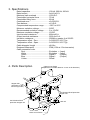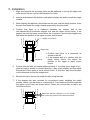
1
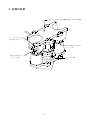
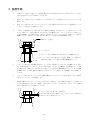
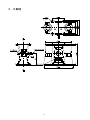
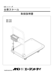
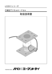
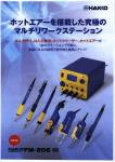
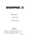
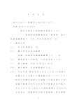
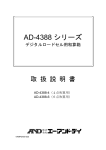
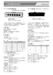
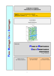
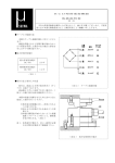
LCC12 シリーズ
ウェイ モジュール
LCC12 Series
Weigh Module
取 扱 説 明 書
Instruction Manual
WM+PD4000785A
MSAWT001
ページ 1
日本語
ご注意
(1) 本書の一部または全部を無断転載することは固くお断りします。
(2) 本書の内容については将来予告なしに変更することがあります。
(3) 本書の内容は万全を期して作成しておりますが、ご不審な点や誤り、記載もれなどお気づき
の点がありましたら、お買い求めの販売店または最寄りの弊社営業所へご連絡ください。
(4) 当社では、本機の運用を理由とする損失、損失利益等の請求については、(3)項にかかわ
らずいかなる責任も負いかねますのでご了承ください。
©
2004 株式会社 エー・アンド・デイ
株式会社エー・アンド・デイの許可なく複製・改変などを行うことはできません。
1. LCC12シリーズ ウェイモジュール一覧
LCC12T010 (定格容量:100kN)
LCC12T020 (定格容量:200kN)
LCC12T030 (定格容量:300kN)
2. 概要
LCC12シリーズ ウェイモジュールは、自動調芯機能を備えた圧縮型ロードセルと振れ止め機
能、浮き上がり防止機能を備えたマウント金具を組み合わせたオールステンレス製計量モジュール
です。100kNから300kNの定格容量のため、大型タンクスケールに適しており、ロードセ
ル本体は溶接密閉構造なのでIP68相当の過酷な環境にも適応します。
調整はストッパーの確認のみで設置やメンテナンスが簡単にできます。また、小型軽量のため設置
場所の自由度も広がります。
ロードセルは精度や応答性に優れている分、設置する機器の構造や設置方法に配慮が必要となりま
す。性能を十分に引き出すためにこの取扱説明書をご理解いただき、正しく設置してください。
3. 仕様
定格容量.........................100kN、200kN、300kN
定格出力.........................2mV/V±0.1%
最大許容過負荷..............150%R.C.
許容水平力 .....................75kN
許容浮上力 .....................80kN
総合誤差.........................±0.03%R.O.
ゼロバランス .................±1%R.O.
温度補償範囲 .................-20°C~60°C
印加電圧下限 .................5VDC
推奨印加電圧 .................5~12VDC
最大印加電圧 .................15VDC
入力端子間抵抗..............800Ω±30Ω
出力端子間抵抗..............2200Ω±10Ω
絶縁抵抗.........................5000MΩ以上/DC50V
温度係数(ゼロ点) ......0.019%R.O./10°C Typ.
温度係数(スパン) ......0.010%R.O./10°C Typ.
ケーブル太さ/長さ ......φ8/12m
保護等級.........................IP68(水深1.5m/100時間)
-1-
ケーブル配線
赤...... 電源+(入力)
白...... 電源-(入力)
緑...... 出力+(出力)
青...... 出力-(出力)
黄...... シールド
4. 各部の名称
上側マウント金具 (許容移動距離:全方向±5mm)
ストッパーボルト
(反対側にもあり)
振れ止め兼浮き上り防止
ストッパー部
振れ止め兼浮き上り防止
ストッパー部
ロードセル本体
下側マウント金具
-2-
5. 設置手順
1.
下側マウント金具、上側マウント金具を固定するための架台およびタンク等のブラケットの取り
付け穴は芯出しをした上で加工しておきます。
2.
架台とタンク等のブラケットの間にジャッキを入れ、タンク等を持ち上げてウェイモジュールを
挿入します。
3.
架台、タンク等のブラケットとウェイモジュールの位置を合わせながらタンク等を降ろし、ウェ
イモジュールをボルトで仮止めします。
4.
一旦タンク等を降ろして、図に示すように振れ止め兼浮き上り防止ストッパー部のストッパーボ
ルトと上側マウント金具の間にすきまがあることを確認します。ストッパーボルトと上側マウン
ト金具が接触している場合はタンク等を少し持ち上げ、ストッパーボルトと上側マウント金具が
接触しないよう下側マウント金具または上側マウント金具の位置を微調整します。
上側マウント金具
ストッパーボルト
• ストッパーボルト両側にすきまがあることを確認すること。
すきま
すきま
•ストッパーボルトが上側マウント金具と接触している場合は、
下側または上側マウント金具の位置を微調整すること。
5.
ストッパー部のすきまが適正であれば、ロードセルが垂直に立っていることを確認します。傾い
ている場合(目安としては±1°以上≒目視で傾いていることが確認できる程度)はタンク等を
少し持ち上げ、下側マウント金具または上側マウント金具の位置微調整によりロードセルの垂直
を調整します。この時、振れ止め兼浮き上り防止ストッパー部のすきまも確認しながら調整して
ください。
6.
ストッパー部のすきま、ロードセルの垂直が適正となったらジャッキを取り除き、ボルトを締め
付けてウェイモジュールを固定します。
7.
設置時の都合によりストッパーボルトを取り外した場合は、ボルト頭部と上側マウント金具との
すきまが約5mmとなるように調整して取り付けてください。ボルトはナットをしっかりと締め
付けてゆるまないように固定してください。
ストッパーボルトを取り外した場合は、
このすきまを約5mmに調整してナットをしっかりと締め付け
ゆるまないように固定すること。
-3-
6. 設置にあたっての注意
・
ロードセルを取り付ける構造物の強度は、荷重に十分耐えられるように設計してください。
・
ロードセルの基礎となる架台は、荷重を支える重要な箇所ですので、施工も入念に行ってください。
・
ロードセルを屋外に設置する場合は直射日光が直接当たらないよう保護対策を施してください。
・
輻射熱、熱風等によりロードセルが高温となる恐れがある場合は、熱に対する保護対策を施して
ください。
・
ロードセルケーブルは突っ張らないようにたるみを持たせてください。また、破損しないよう電
線管等により保護してください。なお、電線管は動力線と共用しないでください。
・
ロードセルケーブルの芯線の色と接続の対応は次の通りです。誤配線には十分注意願います。
赤................電源+
緑 .....................出力+
白................電源-
青 .....................出力-
黄................シールド
・
指示計に通電したままロードセルの接続はしないでください。通電したまま誤配線をするとロー
ドセル内部を破損する恐れがあります。また、通電する時は接続に誤りがないかよく確認してか
ら通電してください。
・
最大印加電圧を越える電圧をロードセルに加えないでください。ロードセル内部を破損する恐れ
があります。
・
ロードセルに強い衝撃を与えないでください。
・
ロードセルを装着したまま溶接作業を行う時は、溶接箇所の近くにアースを取るなどロードセル
に電流が流れないよう配慮をしてください。
7. 日常点検
次の項目について適宜点検してください。
・
ストッパー部のすきまは適正か?ゴミ、異物などは詰まっていないか?
・
ロードセル、マウント金具に付着物はないか?
・
取り付けボルトにゆるみはないか?
・
ロードセルケーブルは突っ張っていないか?
・
ケーブルの接続にゆるみはないか?
・
漏電はないか?
-4-
8. 外観図
-5-
MEMO
English
Note
This manual is subject to change without notice at any time to improve the
product. No part of this manual may be reproduced, transmitted, transcribed, or
translated into any language without the prior written consent of A&D Company
Ltd.
Product specifications are subject to change without any obligation on the part
of the manufacturer.
© 2004
1. LCC12 Series Weigh Modules
LCC12T010
LCC12T020
LCC12T030
(Rated capacity 100 kN )
(Rated capacity 200 kN )
(Rated capacity 300 kN )
2. Introduction
The LCC12 series are stainless steel weigh modules and are composed of a
compression load cell with a self-aligning function and mount fixtures with
built-in anti-vibration mechanism/lift-off protection mechanism.
As the rated capacity range is from 100 kN to 300 kN, the LCC12 series are
optimum for large tank scales.
The LCC12 series can be used in severe environments, equivalent to IP68, as
the load cell is hermetically sealed.
The only required adjustment is checking the stopper units, which allows easy
installation and maintenance.
Being compact and lightweight, the LCC12 series can be installed almost
anywhere.
Consider the system design and installation carefully because for precision
weighing, the load cell is more sensitive. Read this instruction manual carefully,
for correct installation and precision weighing.
-7-
3. Specifications
Rated capacities.....................................100 kN, 200 kN, 300 kN
Rated output...........................................2mV/V±0.1%
Maximum safe overload .........................150%R.C.
Permissible horizontal force ...................75 kN
Permissible lifting force...........................80 kN
Combined error ......................................±0.03%R.O.
Zero balance ..........................................±1%R.O.
Compensated temperature range...........-20°C to 60°C
Minimum excitation voltage ....................5VDC
Recommended excitation voltage ..........5 to 12VDC
Maximum excitation voltage ...................15VDC
Input terminal resistance ........................800Ω±30 Ω
Output terminal resistance......................2200 Ω±10 Ω
Insulation resistance...............................5000M or greater Ω at 50VDC
Temperature effect - Zero.......................0.019%R.O./10°C Typ.
Temperature effect - Span......................0.010%R.O./10°C Typ.
Cable diameter/ length ...........................φ8/12m
Dustproof/Waterproof .............................IP68 (100h at 1.5m immersion)
Cable connection color
Red................................................Excitation + (Input)
White .............................................Excitation - (Input)
Green ............................................Signal +
(Output)
Blue ...............................................Signal (Output)
Yellow............................................Shield
4. Parts Description
Upper mount fixture
(Maximum movable distance: ±5 mm in all directions)
Stopper bolt
(One each on the
left and right side)
Anti-vibration/lift-off protection
stopper unit
Anti-vibration/lift-off
protection stopper unit
Load cell
Lower mount fixture
-8-
5. Installation
1. Align and machine the mounting holes on the platforms to secure the upper and
lower mount fixtures, and on the brackets for a tank.
2. Insert a jack between the platform and tank and raise the tank to install the weigh
module.
3. While aligning the platform, the bracket on the tank, and the weigh module, lower
the tank and attach the weigh module temporarily using the bolts.
4.
Confirm that there is a clearance between the stopper bolt of the
anti-vibration/lift-off protection stopper unit and the upper mount fixture. If the
stopper bolt and the upper mount fixture are in contact, raise the tank slightly and
fine adjust the position of the upper or lower mount fixture.
Upper mount fixture
Stopper bolt
Clearance
• Confirm that there is
shown to the left.
• If the stopper bolt is in
upper mount fixture,
position of the upper
fixture.
Clearance
a clearance as
contact with the
fine adjust the
or lower mount
5. Confirm that the load cell stands perpendicularly. If it is tilted (to an angle of ±1°,
great enough to identify by visual inspection), raise a tank slightly and fine adjust
the position of the upper or lower mount fixture. At this time, pay close attention
to the clearance around the stopper bolt.
6. Remove the jack. Secure the weigh module using the bolts
7. If the stopper bolt was removed for convenience when installing the weigh
module, attach it so that there is a clearance of 5 mm between the bolt head and
the upper mount fixture as shown below. Fasten the nut securely so that it will
not become loose.
Make sure that the clearance is 5 mm. Fasten
the nut securely so that it will not become loose.
-9-
6. Precautions
Design the structure to install the load cell strong enough to withstand the load.
Make the platform strong enough to withstand the load.
Protect the load cell from direct sunlight when the system is installed in the open
air.
If the load cell may be heated by radiated heat or hot air, take measures against
heat.
Leave some slack in the load cell cable so that it will not be pulled.
Install the load cell cable using conduit or flexible tubing.
Separate the load cell cable from any power line.
Connect the wiring correctly.
Red......... Excitation+ (Input)
White ...... Excitation- (Input)
Yellow..... Shield
Green ......Signal+ (Output)
Blue.........Signal- (Output)
Turn off the indicator and other instruments before attaching the load cell. Check
the connection before operating the load cell.
Do not input excessive excitation voltage above the maximum. It will cause
damage to the load cell.
Avoid shock and overload to the load cell.
When welding is executed, ground the earth line and disconnect the load cell
cable from the indicator to protect the load cell and indictor from the welding
current.
7. Maintenance
Check the following items.
Is there the appropriate clearance?
Is there a foreign substance such as mud at the clearance?
Is there a foreign substance on the load cell and the mount fixtures?
Are there loosened bolts?
Is there slack in the load cell cable?
Is there a connection problem?
Is there any current leakage?
- 10 -
8. Dimensions
- 11 -
MEMO