1
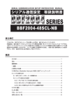
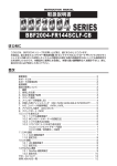
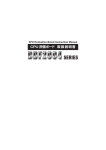
SERIAL COMMUNICATION SETUP INSTRUCTION MANUAL
シリアル通信設定 取扱説明書
SERIES
BBF2004-64SCL-NB
はじめに
このたびは、BBF2004 シリーズをお買い上げ頂き、誠にありがとうございます。
2
本製品は、富士通マイクロエレクトロニクス株式会社製 16 ビットマイクロコントローラ F MC16LX ファミリのフラッシュメモリ内蔵 MCU を使用したシステムの開発を支援する際のシリアル通
信設定方法を説明したものです。シリアル通信での開発をする前に、本取り扱い説明書をよくお読み
下さい。また、後日のために必ず保存しておいて下さい。
目次
はじめに─────────────────────────────────1
目次───────────────────────────────────1
重要事項─────────────────────────────────2
1.概要──────────────────────────────────2
2.使用上の注意──────────────────────────────2
3.デバイス選択──────────────────────────────3
4.シリアル書き込み──────────────────────────── 3
4.1MCU のドータボードへの搭載方法──────────────────3
4.2シリアル書き込み設定────────────────────────4
4.2.1PC/YDC ライタの切り替え設定─────────────────4
4.2.2MCU のシリアル書き込みボード設定───────────────4
4.2.3MCU の書き込みプログラム起動端子設定─────────────4
4.3USB ライタ コネクタ────────────────────────5
5.CAN 通信 ───────────────────────────────5
6.LIN 通信────────────────────────────────5
サポートについて─────────────────────────────6
お問い合わせ一覧─────────────────────────────6
2
重要事項
本ボードをご使用になる前に、本取り扱い説明書をよく読んで理解して下さい。本取り扱い説明書は必
ず保管し、ご使用になっているときや不明な点がある場合は、再度よく読み返して下さい。
本ボードとは:
本ボードとは、サンハヤト株式会社(以降、当社と略す)が製作したつぎの製品です。
(1)BBF2004 メインボード(以降、メインボードと略す)型名:BBF2004-MB
(2)BBF2004 ドータボード(以降、ドータボードと略す)型名:BBF2004-64SCL-NB
お客様のホストコンピュータ、専用エミュレータ (ICE)、シリアルライタ、MCU 搭載用カバーおよびケ
ーブル類は含みません。
本ボードの使用目的:
2
本ボードは、富士通マイクロエレクトロニクス株式会社製 16 ビットマイクロコントローラ F MC16LX ファミリ MCU を使用したシステムの開発を支援する装置です。この使用目的に従って、本ボー
ドを正しくお使い下さい。この使用目的以外のご使用を堅くお断り致します。
使用制限:
本ボードは、開発支援を目的として製作したものです。機器組み込み用として使用しないで下さい。また、
つぎに示す開発用途に対しても使用しないで下さい。
(1)人命にかかわる装置、医療機器用
(2)原子力開発機器用
(3)航空機器開発用 (4)宇宙開発機器用
このような目的で本ボードの採用を検討されるお客様は、事前に当社研究開発本部へご連絡頂きますよ
うお願い致します。
製品の変更について:
製品の改良のため、デザイン・仕様・取り扱い説明書の内容等を予告なく変更することがあります。
1. 概要
本取り扱い説明書は、ドータボードのフラッシュメモリ内蔵 MCU(以降、MCU と略す)のシリアル
書き込み、CAN、LIN の設定方法を説明したものです。お使いになる MCU によって設定方法が異な
ります。本取り扱い説明書を良くお読みになり正しく設定して下さい。
上記以外の設定項目及び使用方法については、メインボードに添付されている、
「CPU 評価ボード取
扱説明書 BBF2004 SERIES」をご覧下さい。
2. 使用上の注意
注 意
本ボードでシリアル通信を行う前に、つぎに示す注意事項を必ずよくお読みになり理解して下さい。
誤ってご使用になりますと、MCU、周辺デバッグ装置、本ボードおよびユーザープログラムの破壊
につながります。
(1)ジャンパースイッチ、ディップスイッチを設定する時は、本ボードおよび周辺デバッグ装置の電
源を必ずお切り下さい。
(2)設定に使用しないジャンパースイッチ用コネクタは、必ず全て取り外して下さい。
(3)シリアル書き込みで設定したジャンパースイッチ、ディップスイッチは作業終了後、設定を必ず
解除して下さい。その後、ご使用になる MCU の動作モードに合わせて「動作モード指定用端子 MD2、
MD0、MD1」をメインボード上のディップスイッチ "SW3" で設定して下さい。MD2、MD0、MD1
の設定方法は、
「CPU 評価ボード取扱説明書 BBF2004 SERIES」4項の「本ボードの使用方法」をご
覧下さい。
「動作モード」の詳細については、富士通マイクロエレクトロニクス株式会社へお問い合わせ
下さい。
(4)本取り扱い説明書内の " XXX " は、ドータボード上のシルク文字を表わします。
2004-64SCL-NB
3
3. デバイス選択
本ボードをご使用になる時は、必ずドータボード上でご使用になるデバイスの
選択設定をしてください。正しく設定されない場合、MCU が正常動作しない
だけでなく、MCU、周辺デバッグ装置、本ボードおよびユーザープログラムの
破壊につながります。
%
【 MB90350 シリーズ使用時 】
JP1 のジャンパースイッチを "MB90350" 側へ付属のジャンパースイッチ用
コネクタで短絡します。C 端子(50 番ピン)が 0.1uF コンデンサを介して
GND へ接続されます。
(図 3 - 1 参照)
【 MB96350 シリーズ使用時 】
JP1 のジャンパースイッチを "MB96350" 側へ付属のジャンパースイッチ用
コネクタで短絡します。C 端子(50 番ピン)が 10uF コンデンサを介して
GND へ接続されます。
(図 3 - 2 参照)
/$
RKP
/$
,2
図3−1
/$
RKP
/$
%
,2
図3− 2
4. シリアル書き込み
警告
(1)本ボードの電源を入れた状態で、IC ソケットに対して MCU の脱着を行わないで下さい。電
源を入れた状態で MCU の脱着を行った場合は、ホストコンピュータ、本ボード、周辺デバッ
グ装置および MCU の破壊または発煙、発火の可能性があります。また、評価中のユーザープ
ログラムを破壊する可能性があります。
(2)MCU の搭載方向には十分ご注意下さい。方向を誤って搭載した場合、MCU、本ボードおよ
び周辺デバッグ装置の破壊または発煙、発火の可能性があります。
本ボードは富士通マイクロエレクトロニクス製 FUJITSU MICROELECTRONICS FLASH MCU
Programmer( 以 降、PC ラ イ タ と 略 す )
、FUJITSU MICROELECTRONICS FLASH USB
Programmer(以降、
USB ライタと略す)
、
および横河ディジタルコンピューター製シリアルライタ(以
降、YDC ライタと略す)を使用し、オンボードで MCU にシリアル書き込みができます。
(補足)
PC ライタ
USB ライタ :RS232C 使用時
:BGM アダプタ使用時
シリアル書き込みを行う場合は、必ずご使用になる書き込み方法に合わせて正しく設定してくださ
い。YDC ライタ使用時の MCU への電源供給方法は、本ボードからの電源供給のみに対応しており、
YDC ライタからの電源供給には対応していません。
なお、PC ライタ、USB ライタ、については富士通マイクロエレクトロニクス株式会社へ、YDC ラ
イタについては横河ディジタルコンピュータ株式会社へお問い合わせ下さい。
4.1 MCU のドータボードへの搭載方法
*32#%-5&
IC ソケットに MCU を搭載するときは、MCU のピンの曲がりなどが無いことを
確認して下さい。その後、ドータボード上の 1 番ピン表示と MCU の 1 番ピン
を合わせて、MCU を IC ソケット "NS1" へ搭載して下さい。
(図 4 - 1 参照)
MCU 搭載用カバーは、HQPACK064SD(東京エレテック株式会社)をご使
用下さい。このカバーは当社で販売しています。
2004-64SCL-NB
/%7
05
図 4 −1
4
4. シリアル書き込み
【PC ライタ使用時】ディップスイッチ "SW3"
の 7、
8 番を ON にします。
同時に USB ライタ、
PC ライタを接続しないでください。正常動作
致しません。
4.2 シリアル書き込み設定
シリアル書き込みを行う場合は、下記3種類の設定が必要です。この設定
は、必ずご使用になる書き込み方法に合わせて正しく設定して下さい。
SW3
ON
1
2
3
(1)PC/USB/YDC ライタの切り替え設定
(2)MCU のシリアル書き込みモード設定
(3)MCU の書き込みプログラム起動端子設定
4
5
6
P-SIN
P-SOT
7
8
Y-SIN
Y-SOT
9 10
4.2.1
PC/USB/YDC ライタの切り替え設定
使用するライタに合わせて、メインボード上のディップスイッチ
"SW3" の 7 番、8 番を設定して下さい。
( 図 4 - 2、図 4 - 3 参照)
図 4 −2
【USB/YDC ライタ使用時】ディップスイッ
チ "SW3" の 7、8 番を OFF にします。同時
に USB ライタ、YDC ライタを接続しないで
ください。正常動作致しません。
SW3
ON
1
2
4.2.2 MCU のシリアル書き込みモード設定
PC/USB/YDC ライタ共通
MD2(21 番ピン)= 'H'、MD1(22 番ピン)= 'H''、MD0(23
番ピン)= 'L' に設定する為に、メインボード上のディップスイッ
チ "SW3" の 1 番を OFF、2 番を ON、3 番を ON にします。
(図 4 - 4 参照)
MB96340/MB96350 の場合は、MD2='L' にするため、
ディップスイッチ "SW3" の3番を OFF にします。
3
4
5
6
P-SIN
P-SOT
7
8
Y-SIN
Y-SOT
9 10
図 4 −3
59
4.2.3 MCU の書き込みプログラム起動端子設定
書き込みプログラム起動端子を、ご使用になる MCU およびライ
タに合わせてメインボード上のディップスイッチ“SW3”の 9 番、
10 番を設定してください。メインボード上のジャンパースイッチ
“PX0”、
“PX1”をジャンパースイッチ用コネクタで接続すること
によりディップスイッチ“SW3”の 9 番、10 番の設定が有効に
なります。
10
/&
/&
/&
図 4 −4
59
10
【MB90F352/S/C/CS の場合】
MB96340/MB96350 の場合は、下記(1)と(2)の設定は不要。
2:
2:
2:
2:
図 4 −5
59
59
2:
2:
図 4 −6
2:
2:
2:
2:
2004-64SCL-NB
(2)YDC/USB ライタによる書き込みを行う時
“SW3”の 9 番を OFF にします。
“SW3”の 10 番を ON にします。 (図4-7参照)
10
・原発振周波数:5MHz、10MHz のいずれかの時、
“SW3”の 9 番を ON にします。
“SW3”の 10 番を OFF にします。 (図4-6参照)
10
(1)PC ライタによる書き込みを行う時
・原発振周波数:4MHz、8MHz、16MHz のいずれかの時、
“SW3”の 9 番を OFF にします。
“SW3”の 10 番を OFF にします。 (図4-5参照)
2:
2:
図4−7
5
4. シリアル書き込み
4.3 USB ライタコネクタ
BGM アダプタ MB2146-09 は、ドータボード上のコネクタ(CN6)
へ接続してください。(図 4 - 8 参照)
図4−8
5.CAN 通信
CAN 通信を行う時は、ドータボード上のジャンパースイッチ“TxD”
(JP6)、“RxD”(JP7) をジャンパースイッチ用コネクタで接続してく
ださい。( TxD=TX1(MCU 17 番ピン )、RxD=Rx1(MCU 16 番ピ
ン))接続することにより、CAN 通信が可能となります。CAN 通信用
D-SUB コネクタは、ドータボード上の“CAN1 Connector”(CN5)
を使用してください。
(図5-1参照)
%#0
,2
6Z&
6Z
4Z&
%#0%QPPGEVQT
4Z
,2
%0
図5−1
6.LIN 通信
警告
LIN トランシーバーへ誤った電源供給はしないように十分注意してください。誤った電源供給をし
た場合、MCU、ホストコンピュータ、本ボードおよび周辺デバッグ装置の破壊または発煙、発火の
可能性があります。
LIN 通信を行う時は、ドータボード上のジャンパースイッチ“TxD”(JP4)、
“RxD”(JP2)、
“NSLP”
(JP3) をジャンパースイッチ用コネクタで接続してください( TxD=SOT2(MCU 10 番ピン )、
RxD=SIN2(MCU 9 番ピン)
)
。 接続することにより、LIN 通信が可能となります。Master node
として使用する場合は、ジャンパースイッチ“NWAKE”(JP5) をジャンパースイッチ用コネクタで
接続してください。
(Slave node として使用する場合は未接続)
ドータボード上の LIN 通信端子“LIN bus”
“BAT(VCC)”
、
、
“GND”に必要な接続をしてください。
(図6-1参照)
.+0
,2
6Z&
516
,2
4Z&
5+0
,2
05.2
,2 09#-'
“BAT(VCC)”、
“GND”への電源供給(安定化電源)は、
お客様でご用意ください。
LIN トランシーバーの消費電流は 10mA 以下です。
【MB90350E シリーズ、MB96350 シリーズの場合】
ドータボード上のジャンパースイッチ“NSLP”をジャン
パースイッチ用コネクタで接続することにより MCU のポ
ート P11(33 番ピン)でドータボード上の LIN トラン
シーバーを制御します。ポート P11 の出力が’H’の時、
LIN 通信が可能となります。
62
62
$#6
8%%
)0&
2
.+0DWU
62
.+0DWU
図6−1
2004-64SCL-NB
6
サポートについて
本ボードのシリアル通信の設定および技術的なお問い合わせは、当社研究開発本部へお問い合わせ下
さい。
お問い合わせ一覧
サンハヤト株式会社 研究開発本部
〒 170-0005 東京都豊島区南大塚 3-40-1
電話番号:03-5951-4821(直通)
FAX 番号:03-5985-7667
【横河ディジタルコンピュータ株式会社製シリアルライタについてのお問い合わせ先】
横河ディジタルコンピュータ株式会社 機器事業部 サポートセンタ
〒 183-8540 東京都府中市府中町 1-9 京王府中 1 丁目ビル
電話番号:042-333-6245 FAX 番号:042-352-6107
【PC/USB シリアルライタについてのお問い合わせ先】
富士通セミコンダクター株式会社
〒 222-0033 神奈川県横浜市港北区新横浜 2-10-23 野村不動産新横浜ビル
【車載用途でご使用のお客様向け問合せ先】
自動車事業部 ソリューション技術部
電話 :045-755-7044
【車載以外の用途でご使用のお客様向け問合せ先】
汎用品事業部 ソリューション技術部
電話 :045-755-7037
2004-64SCL-NB
SERIAL COMMUNICATION SETUP
INSTRUCTION MANUAL
SERIES
BBF2004-64SCL-NB
Preface
Thank you very much for buying the BBF2004 series product.
This instruction manual explains the method to set up serial communication to be used in
supporting the development of a system using an MCU with a built-in Flash memory of Fujitsu
16-bit micro-controller, F 2 MC-16LX family. Read this instruction manual carefully before starting
the development with serial communication. Also keep this manual for use in the future.
Contents
Preface────────────────────────────────────────────────7
Contents───────────────────────────────────────────────7
Important Items───────────────────────────────────────────8
1. Outline ────────────────────────────────────────────── 8
2. Notes on Use ──────────────────────────────────────────8
3. Selecting for Device────────────────────────────────────── 9
4. Serial Writing────────────────────────────────────────── 9
4.1 Installation of MCU on Daughter Board─────────────────────── 9
4.2 Setting for Serial Writing────────────────────────────────10
4.2.1 Setting for PC/YDC writer switchover───────────────────── 10
4.2.2 Setting for MCU serial writing mode──────────────────────10
4.2.3 Setting for MCU writing program starting pins────────────────10
4.3 USB Writer connector──────────────────────────────────11
5. CAN Communication───────────────────────────────────── 11
6. LIN Communication──────────────────────────────────────11
Support ───────────────────────────────────────────────1 2
List of contact windows for inquiries ─────────────────────────────1 2
8
Important Items
Before using this board, read this instruction manual carefully and understand its contents. Keep
this instruction manual and, when you encounter a problem while using this board, read it again.
What this board is
This board is one of the following products manufactured by Sunhayato Corporation (hereinafter
called the company).
(1) BBF2004 main board (hereinafter called the main board) Type No.: BBF2004-MB
(2) BBF2004 daughter board (hereinafter called the daughter board) Type No.: BBF2004-64SCL-NB
The customer's host computer, dedicated emulator (ICE), serial writer, MCU mounting cover and
cables are not included.
Application of this board
This board supports the development of a system by using Fujitsu 16-bit micro-controller, F 2 MC16LX family MCU. Use this board correctly for this purpose. Do not use it for other purposes.
Constraints
This board is manufactured to support the development. Do not use it as the built-in board for a
device. Also do not use it for the following development purposes.
(1) For life-related and medical devices
(2) For nuclear power development devices
(3) For aircraft device development
(4) For space development devices
Any customer who considers the use of this board for any of the above purposes should contact
Research and Development Div. of the company in advance.
Change in product
To improve the product, its design and specifications, and the contents of the instruction manual
may be revised without prior notice.
1. Outline
This instruction manual explains the setting method used in evaluating serial writing and CAN, LIN
communication with the MCU with the built-in Flash memory on the daughter board. The setting
method depends on the MCU to be used. Read this instruction manual carefully and make the setting
correctly. For details on setting items and operation methods other than explained above, refer to
"CPU Evaluation Board Instruction manual BBF2004 SERIES" that comes up with the main board.
2. Notes on Use
Caution
Before making serial communication with this board, read the following notes carefully and
understand them well. If this board is used incorrectly, the MCU, peripheral debugging device,
this board, or user programs may be destroyed.
(1) To set a jumper wire or DIP switch, turn off the power of this board and that of the peripheral debugging device.
(2) Remove all jumper wires not to be used for setting.
(3) After serial writing operation and CAN, LIN communication operation are finished, cancel the settings
of the jumper wire and DIP switch that are set for that serial writing and USB communication. Then,
use DIP switch "SW3" on the main board to set Operation mode specification pins, MD2, MD1 and MD0
to the operation mode of the MCU to be used. For details on setting pins MD2, MD1 and MD0, refer to
"Using this Board" in Item 4 in "CPU Evaluation Board Instruction manual BBF2004 SERIES." For
details on the operation mode, contact Fujitsu Microelectronics Limited.
(4) "XXX" in this instruction manual indicates a silk-print character on the daughter board.
2004-64SCL-NB
9
3. Selecting for Device
For using this board, the following setting is required.
Be very careful not to incorrectly set jumper switch otherwise, the MCU, host
computer, this board, or peripheral debugging device may be destroyed or
emit smoke or catch fire.
%
[MB90350 Series]
When use MB90350 Series MCU, connect jumper switch “JP1” and “JP8” on the
daughter board with a jumper switch connector to set “MB90350”. Signal C pin (No.
50 pin) through a 0.1uF capacitor connected to GND. (Figure 3-1)
[MB96350 Series]
When use MB96350 Series MCU, connect jumper switches “JP1” on the daughter
board with a jumper switch connector to set “MB96350”. Signal C pin (No. 50 pin)
through a 10uF capacitor connected to GND. (Figure 3-2)
/$
RKP
/$
,2
Figure 3-1
/$
RKP
/$
%
,2
Figure 3-2
4. Serial Writing
Warning
(1)
(2)
Do not connect the MCU to the IC socket or disconnect it from that socket with the power of
this board turned on; otherwise, the host computer, this board, peripheral debugging device,
or MCU may be destroyed or emit smoke or catch fire. The user programs being evaluated
may also be destroyed.
Be very careful about the direction in which the MCU is mounted. If the direction is incorrect,
the MCU, this board, or peripheral debugging device may be destroyed or emit smoke or
catch fire.
By using this board and a FUJITSU MICROELECTRONICS FLASH MCU Programmer (hereinafter
called the PC writer) or FUJITSU MICROELECTRONICS FLASH USB Programmer (hereinafter
called the USB writer) or Yokogawa Digital Computer serial writer (hereinafter called the YDC
writer), serial writing to the on-board MCU is enabled.
(Note)
Usage of PC writer: Connect a RS232C cable
Usage of USB writer: Connect a BGM connector
When the YDC writer is used, the power can be supplied to the MCU from the main board, but not
from the YDC. For information about the PC writer and USB writer, contact Fujitsu Microelectronics
Limited. For information about the YDC writer, contact Yokogawa Digital Computer Corporation.
4.1 Installation of MCU on Daughter Board
When the MCU is mounted on the IC socket, confirm that the MCU pins are
straight. Then, mount the MCU on IC socket "NS1" with the MCU No. 1 pin to
the No. 1 pin mark on the daughter board. (Figure 4-1)
*32#%-5&
/%7
Use HQPACK064SD (Tokyo Eletech Corporation) as an MCU mounting cover. The company sells this cover.
05
Figure 4-1
2004-64SCL-NB
10
4. Serial Writing
[When PC writer is used]Set No. 7 and
No. 8 of DIP Switch "SW3" to 'ON.'Be
careful not to connect USB writer and
PC writer at the same time.
4.2 Setting for Serial Writing
For serial writing, the following three settings are required.
Make these settings correctly for the writing method to be used.
(1) Setting for PC/USB/YDC writer switchover
(2) Setting for MCU serial writing mode
(3) Setting for MCU writing program starting pins
SW3
ON
1
2
3
4
5
6
9 10
Figure 4-2
[When USB/YDC writer is used]Set No.7
and No.8 of DIP Switch “SW3” to 'OFF'.
Be careful not to connect USB writer and
YDC writer at the same time.
Setting for MCU serial writing mode
Common to PC, USB and YDC writers
To put the MCU in serial writing mode (MD2 (No. 21 pin) = 'H',
MD1 (No. 22 pin) = 'H', MD0 (No. 23 pin) = 'L'), set No. 1 to 'OFF',
No. 2 to 'ON' and No. 3 to 'ON' of DIP Switch "SW3" on the main
board. (Figure 4-4)
When use MB96340/MB96350, for MD2 = ' L ', set No. 3 to ' OFF '
of the DIP Switch "SW3" on the main board.
SW3
ON
1
2
3
4
5
6
P-SIN
P-SOT
8
Y-SIN
Y-SOT
7
9 10
4.2.2
8
4.2.1 Setting for PC/USB/YDC writer switchover
Set No. 7 and No. 8 of DIP Switch "SW3" on the main board appropriately for the writer to be used. (Figure 4-2, 4-3)
P-SIN
P-SOT
7
Y-SIN
Y-SOT
Figure 4-3
59
/&
/&
/&
10
4.2.3 Setting for MCU writing program starting pins
Set No.9 and No.10 of DIP Switch “SW3”, writing program starting pins,
on the main board appropriately for MCU and writer to be used. Connect
jumper switches “PX0” and “PX1” on the main board with a jumper
switch connector to enable No.9 and No.10 of DIP Switch “SW3”.
[MB90F352/S/C/CS series]
When use MB96340/MB96350, following settings are unnecessary.
Figure 4-4
59
10
(1) Writing with PC writer
Oscillation frequency: 4MHz or 8MHz or 16MHz
Set No. 9 to 'OFF', No. 10 to 'OFF' of DIP Switch "SW3" on the main
board (Figure 4-5)
Oscillation frequency: 5MHz or 10MHz
Set No. 9 to 'ON', No. 10 to 'OFF' of DIP Switch "SW3" on the main
board (Figure 4-6)
2:
2:
2:
2:
Figure 4-5
59
2:
2:
Figure 4-6
2:
2:
2:
2:
Set No. 9 to 'OFF', No. 10 to 'ON' of DIP Switch "SW3" on the main
board (Figure 4-7)
10
10
(2) Writing with YDC/USB writer
59
2:
2:
Figure 4-7
2004-64SCL-NB
11
4. Serial Writing
4.3 USB writer connector
/$
Connect a user interface connector of BGM adapter MB2146-09 to a
connector "CN6" on the daughter. (Figure 4-8)
%0
%QPPGEVQTHQTVJG/$
Figure 4-8
5. CAN Communication
When CAN communication is performed, connect jumper switches
"TxD" (JP6) and "RxD" (JP7) on the daughter board with a jumper
switch connector. (TxD = Tx1 (MCU 17 pin), RxD = Rx1 (MCU 16
pin). This connection enables CAN communication.
Use "CN5"(ch1) on the daughter board as the D-SUB connector for
CAN communication.
%#0
,2
6Z&
6Z
4Z&
%#0%QPPGEVQT
4Z
,2
%0
Figure 5-1
6. LIN Communication
Warning
Be very careful not to incorrectly supply the power to the LIN transceiver; otherwise, the MCU,
host computer, this board, or peripheral debugging device may be destroyed or emit smoke or
catch fire.
When LIN communication is performed, connect jumper switches "TxD"(JP4), "RxD"(JP2) and
"NSLP"(JP3) on the daughter board with a jumper switch connector. (TxD = SOT2 (MCU 10 pin),
RxD = SIN2 (MCU 9 pin). This connection enables LIN communication. In case of the master node,
connect jumper switch "NWAKE" (JP5) with a jumper switch connector. (In case of the slave node,
don't connect jumper switch "NWAKE" with a jumper switch connector.)
Make necessary connections to LIN communication
s w i t c h e s " L I N b u s , " " B AT ( V C C ) , " a n d " G N D " o n t h e
daughter board. (Figure 6-1)
.+0
,2
6Z&
516
,2
4Z&
5+0
,2
05.2
,2 09#-'
Prepare the power supply (stabilized power supply) to
"BAT (VCC)" and "GND." The current consumption of the
LIN transceiver is 10mA or less.
[MB90350E series, MB96350 series]
Connect jumper switch "NSLP" on the daughter board with
a jumper switch connector to control the LIN transceiver
on the daughter board with MCU port P11 (No. 33 pin).
W h e n t h e p o r t P 11 o u t p u t i s " H , " L I N c o m m u n i c a t i o n
becomes possible.
2004-64SCL-NB
62
62
$#6
8%%
)0&
2
.+0DWU
62
.+0DWU
+PECUGQHVJGOCUVGT
PQFGEQPPGEVLWORGT
UYKVEJ09#-'YKVJC
LWORGTEQPPEGEVQT
.+0EQOOWPKECVKQPRKP
2QYGTUWRRN[HQTVJG
.+0VTCPUEGKXGT
8
2QYGTUWRRN[HQTVJG
.+0VTCPUEGKXGT
)0&
Figure 6-1
Support
For the serial communication settings of this board and other technical inquiries, contact the
company's Research and Development Div.
List of contact windows
Research and Development Div.
Sunhayato Corp.
3-40-1, Minami-Otsuka, Toshima-ku, Tokyo, 170-0005, Japan
Phone: +81-3-5951-4821 (direct) FAX: +81-3-5985-7667
[Contact window for inquires about Yokogawa Digital Computer Corporation serial writer]
Support Center, Instrument Bussiness Div.
Yokogawa Digital Computer Corporation
Keio-Fuchu 1-Chome Building
1-9, Fuchu-cho, Fuchu-shi, Tokyo, 183-8540, Japan
Phone: +81-42-333-6245 FAX: +81-42-352-6107
[Contact window for inquires about PC/USB serial writer]
Fujitsu Semiconductor Limited
2-10-23, Shin-yokohama, Kouhoku-ku, Yokohama, Kanagawa, 222-0033, JAPAN
[For Automotive customers]
Solution Engineering Dept. Automotive Business Div.
Phone: +81-45-755-7044
[For Non Automotive customers]
Solution Engineering Dept. Standard Embeded Products Business Div.
Phone: +81-45-755-7037
2010.07.15 MNL-BBF2004-64SCL-NB Rev.2.0