1
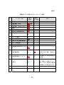
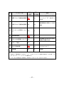
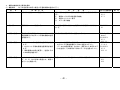
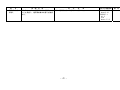
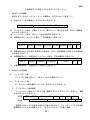
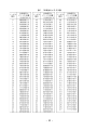
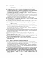
別表 1 情報通信審議会情報通信技術分科会 海上無線通信委員会 構成員 (五十音順・敬称略) 区分 主査 氏名 す ず き 鈴木 み き つとむ 務 て つ や 主査代理 三木 哲也 専門委員 市野 芳明 い ち の い と う 伊藤 い ま い 今井 しんじょう 新城 すけむね 資宗 なかじま 中島 なかむら 中村 やま さき 山﨑 よしあき このむ 好 ただよし 忠義 たつろう 達郎 よ しゆき 克行 さとし 敏 かつひで 勝英 やすはる 保昭 所属 電気通信大学名誉教授、日本工業大学名誉教授 電気通信大学 理事 (財)テレコムエンジニアリングセンター理事 (社)日本船主協会 通信問題サブW/Gグループ長 海上保安庁交通部整備課長 海上保安庁総務部情報通信課長 (※ 平成 20 年5月から) 情報通信ネットワーク産業協会専務理事 海上保安庁総務部情報通信企画課長 (※ 平成 20 年5月まで) 水洋会事務局長 全国遠洋鮪漁撈通信協議会 - 34 - 技術顧問 別表 2 情報通信審議会情報通信技術分科会 海上無線通信委員会作業班 構成員 (五十音順・敬称略) 区分 主任 構成員 氏名 所属 なかむら かつひで あんどう 安藤 勝美 かつみ 日本無線株式会社 うつみ くにお 水産庁 資源管理部管理課 漁船管理班 課長補佐 中村 勝英 内海 邦夫 おおい 大井 おおにし きよし 清 やすふみ 大西 泰史 きくち 菊池 さいとう たけし 剛 はるお 齋藤 春夫 さいとう みつあき 斎藤 光明 さかい えい た 阪井 英太 さかぐち ただお たにみち ゆきお 坂口 忠男 水洋会 事務局長 (※ 海上機器事業部 海上機器技術部 担当部長 平成 20 年 3 月まで) 社団法人 全国漁業無線協会 専務理事 国土交通省 海事局安全基準課 海上保安庁 総務部 情報通信課 課長補佐 (※ 平成 20 年 4 月から) 水産庁 資源管理部管理課 漁船管理班 課長補佐 (※ 平成 20 年 4 月から) 社団法人 日本船主協会 海務部 (※ 平成 20 年 2 月から) 株式会社トキメック 第 1 制御事業部 船舶港湾事業 技術部 第2技術課 古野電気株式会社 舶用機器事業部 国内営業部 営業開発課 (※ 小型船舶救急連絡装置担当) 谷道 幸雄 社団法人全国船舶無線工事協会 たはら たかよし 古野電気株式会社 田原 孝義 とおやま 遠山 なかがわ おさむ 修 えいしん 中川 永伸 はたけやま 畠山 ひらばやし 平林 ほその ひとし 仁 みつお 光雄 ゆうじ 細野 雄二 やまもと たいぞう やうち たかまさ 山本 泰三 矢内 崇雅 専門官 業務部長 舶用機器事業部 営業企画部 企画担当部長 (※ 簡易型AIS担当) 株式会社ゼニライトブイ 技術開発部 技術開発グループ グループ長 財団法人 テレコムエンジニアリングセンター 海上保安庁 交通部 整備課 信号施設室 主任信号施設技術官 太洋無線株式会社 技術部 海洋システム課長 海上保安庁 総務部 情報通信業務課 課長補佐 (※ 平成 20 年 3 月まで) 社団法人 日本船主協会 海務部 課長代理 (※ 平成 20 年 1 月まで) 株式会社沖コンサルティングソリューションズ - 35 - 別紙 1 簡易型 AIS で交換されるメッセージ一覧表 No. メッセージ名 受信と 処理 ※1 自局に 0 未定義 1 位置通報(定期) Yes 2 Yes No Yes No 4 位置通報(割当) 位置通報(呼掛けを受けた 場合) 基地局通報 Yes No 5 静的及び航海関係情報 Yes No No No 3 6 宛先指定バイナリメッセー ジ ※2 No 7 バイナリ認知 No No 8 バイナリ放送メッセージ Yes No 9 標準 SAR 航空機位置通報 Opt No 10 UTC と日付要求 No No 11 UTC/日付応答 Opt No Yes No 12 安全関係宛先指定メッセー ジ 注釈 よる送信 msg12 を処理するオプション 13 安全関係認知 No Yes が実行される場合、送信され ること 14 安全関係放送メッセージ Yes Opt 予め決められた定型文のみで の送信 CSAIS は、msg18 と msg24 を求 15 呼掛け Yes No めた呼掛けに応答すること。 また、msg19 を求めた基地局 の呼掛けにも応答すること。 16 17 割当モード指令 DGNSS 放送バイナリメッセ ージ No No Opt No - 36 - No. メッセージ名 受信と 自局に 処理 a よる送信 注釈 CSAIS はフラグビット 143 を 18 標準 Class B 装置位置通報 Yes Yes “1”として“CS”であること を示す 19 拡張 Class B 装置位置通報 データリンク管理メッセー 20 ジ Opt Yes Yes No 海岸局呼掛け応答としてのみ 送信 21 航路標識通報 Yes No 22 チャンネル管理メッセージ Yes No 23 グループ割当 Yes No 24 CSAIS 静的情報 Yes Yes A と B の 2 タイプ 未定義 No No 拡張用 25– 63 ※1 当該機能の使用は特定地域で は異なる場合がある 本表で“受信と処理”とは、例えばインタフェースや表示への出力等、ユーザにとって明白な機能を 意味する。同期の場合、IEC62287-1 7.3.1.1 に従ってメッセージを受信し処理することが必要;これ はメッセージ 1、2、3、4、18、19 に適用される。 ※2 “Yes”のうち下線を引いた項目は、IEC62287-1 において”Opt”とされているもの。 - 37 - 簡易型 AIS の試験方法 別紙 2 1.外観及び構造試験 項 目 1. 外観及び構造 試 験 方 法 判 定 基 準 対応する国際基準 外観、構造、寸法、重量等を取扱説明書と 1. 取扱説明書の記述を満足していること。 照合して確認する。 IEC80/426/FDIS 2. 次の構造のものであること。 IEC62287-1 (1) 装置は、次の機能を有すること。 6.1 ア. TDMA 送信 イ. TDMA2 チャネル同時受信 ウ. CH70 での DSC 受信 エ. GNSS 受信部 オ. インターフェイス (2) 迅速かつ確実な作動ができ、不必要な作動は最小限と IMO A.694(17) Annex 3.1 すること。 Annex 3.2 (3) 制御部は通常の調整が容易に行え、容易に識別できる 構造であること。また、通常必要のない操作は容易に行 えない構造であること。 Annex 3.3 (4) 制御器の識別及び表示器の読み取りのために照明を 備える場合には、照度調節器を備え航行に支障が無いよ うに調整できること。 Annex 3.4 (5) 誤操作により故障を生じたり、人を傷つける構造でな いこと。 Annex 3.5 (6) 他の装置と接続する場合には、相互に性能を維持する こと。 Annex 3.6 (7) “0”から“9”までの数字入力キーが備え付けられて いる場合には、その配置は ITU-T 勧告 E.161 又は ISO3791 によること。 Annex 4.2 (8) 装置は、過電流、過電圧及び過度的又は偶発的な逆電 圧から保護されていること。 - 38 - 備 考 項 目 1. 外観及び構造 つづき 2. 表示確認 試 験 方 法 判 定 基 準 対応する国際基準 装置の 55V を超えるピーク電圧が印加される帯電部 IMO A.694(17) Annex 7.1 は、容易に露出しないように、次のいずれかの構造の保 護カバーを有すること。 ア. カバーを開けることにより自動的に電流が遮断され ること。 イ. 工具等を用いてカバーを開ける構造であり、高電圧を 示す注意銘板が装置内及び保護カバー双方に備え付け られていること。 Annex 7.2 (10) 露出金属部は、接地できる構造であること。 Annex 8.1 (11) 装置の主構成品は、煩雑な補正又は調整をすることな く、容易に交換できること。 Annex 8.2 (12) 装置は検査、保守が容易に行えるような設計、構造で あること。 (9) 1. 機 器 に 備 え ら れ て い る 資 料 を 確 認 す 1. 操作説明書に加え、保守の為に以下の資料が備えられて IMO A.694(17) Annex 8.3 いること。 る。 (1) 故障の診断、修理が構成部品レベルで可能なように設 計されている場合 ア. 完全な回路図 イ. 部品配置図 ウ. 部品表 (2) 故障の診断、修理が構成部品レベルで可能なように 設計されていない場合 ア. 故障したユニットの識別、交換を可能にする資料 2. 装置の外部に表示されている事項等を 2. 次の事項について装置の外部に表示されるか、又は表示 し得るようになっていること。 確認する。 (1) 装置の名称、型式、製造年月、製造番号及び製造者名 (2) 操舵室に装備する機器にあっては磁気コンパス安全距離 - 39 - Annex 9 IEC60945(Ed4) 11.2.2 備 考 2.機器の機械的及び電気的条件 (1) 機能条件 (以下の各項目は次号に規定する通常試験の温度で行う。) 項 目 試 験 方 法 判 定 基 準 対応する国際基準 1. 制御部 制御部の機能について確認する。 機器の動作と並行して適当な周期で機器の自己診断が行わ IEC 62287-1 6.6.1 れる。 6.7.1 (1) 電源オン及び正常送信表示機能 (2) 送信タイムアウト表示 (3) エラー表示機能 2. 電 電源供給について確認する。 この装置の電源は、船舶の主電源及び代替電源から供給され IEC 62287-1 ること。 9.1 源 3. 情報の送信 4. 情報の更新 5. 情報の受信 静的及び動的情報を入力し、msg18 による 静的及び動的情報が正常に送信されること。 位置情報及び msg24 による静的情報の送信 を確認する。 ITU-R M.1371-3 Annex7 IEC 62287-1 6.5.1 10.2.1.1 1. msg18 による位置情報送信間隔を確認 1. msg18 の送信間隔は規定時間の±10%以内であること。 ITU-R M.1371 2. msg24 による静的情報が 6 分毎に送信されること。 3.3.4.4 する。 2. msg24 による静的情報送信間隔を確認 3. データの内容変更後 1 分以内に、変更された MSG24 のデ IEC 62287-1 ータを送信し、その後再び 6 分毎にデータを送信すること。 6.5.2 する。 10.2.1.1 3. 静的情報の内容を変更し、送信するま での時間を確認する。 msg1, 2, 3, 4, 5, 8, 12, 14, 15, 18, 20, 21, 22, 23, 24 が正常に受信され、処理で きることを確認する。 受信したメッセージに基づいて、正常に処理すること。 - 40 - IEC 61993-2 6.11 10.2 備 考 項 目 試 験 方 法 判 定 基 準 6. 運 用 周 波 数 の DSC 又は msg22 で運用周波数の切替えコマ 正常に運用周波数の切替えができること。 切替え ンドを受信し、運用周波数の切替えを確認 する。 - 41 - 対応する国際基準 ITU-R M.1371 Annex2 4.1 IEC62287-1 4.1.5 10.4 Annex C.3.2 備 考 (2) TDMA 送信部 項 目 試 験 方 法 判 定 基 準 対応する国際基準 1. 周 波 数 許 容 偏 スイッチ投入 2 分後の機器を無変調状態で 周波数偏差は、通常試験環境において±0.5kHz 以下、限界 ITU-R M.1371-2 差 搬送波のみを出力したときの周波数偏差 試験環境において±1.0kHz 以下となること。 IMO MSC74(69) を測定する。 Annex3/7 IEC 62287-1 11.1.1 2. 送信電力 スイッチ投入 2 分後、希望周波数において 搬送波電力は、通常試験環境において 33dB±1.5dB、限界試 ITU-R M.1371-2 テストメッセージで変調された信号を出 験環境において 33dB±3dB となること。 Annex2 力したときの平均電力を測定する。 2.13.2 IMO MSC74(69) Annex3/7 IEC 62287-1 11.1.2 3. 占 有 周 波 数 帯 希望周波数において占有周波数帯幅が最 スペクトル分布が、下図の範囲内のレベルとなること。 幅 大となる変調状態、もしくは通常運用され 占有帯域幅は、16kHz 以内であること。 ている信号のうち、占有周波数帯幅が最大 となる信号による変調状態において、スペ クトル分布の全電力をスペクトルアナラ イザ等により測定する。そして、スペクト ル分布の上限及び下限部分の電力和が、そ れぞれ全電力の 0.5%となる周波数幅を測 定する。 - 42 - IU-R M.1371 Annex2 2.4.2 IEC 62287-1 11.1.3.3 備 考 項 目 試 験 方 法 判 定 基 準 4. ス プ リ ア ス 発 1. 帯域外領域(搬送波から±12.5kHz か 1. スプリアス発射の強度は、2.5μW 以下であること。 射及び不要発射 ら±62.5kHz までの周波数領域)のスプ 2. 不要発射の強度は、2.5μW 以下であること。 の強度 リアス発射の強度を、無変調送信状態に おいて測定する。 2. ス プ リ ア ス 領 域 ( 基 本 周 波 数 か ら ± 62.5kHz 以上離れた周波数領域)の不要 発射強度を、テストメッセージで変調又 は必要に応じ無変調送信状態において、 9kHz から第 10 次高調波までの周波数範 囲にて測定する。 対応する国際基準 ITU-R M.329-8 Category D 5. 送 信 タ イ ミ ン 1. 希望周波数においてテストメッセー 1. 送信開始後 0.3ms(3bits)以内であること。 グ特性 ジで変調した試験信号の送信出力が、送 2. 送信終了後 0.3ms(3bits)以内であること。 信開始後安定状態の-3dB に達するまで の時間を測定する。 2. 希望周波数においてテストメッセー ジで変調した試験信号の送信出力が、送 信を終了後 50dB 低下するまでの時間を 測定する。 ITU-R M.1371 Annex2 2.12.1 IEC 62287-1 11.1.5 6. 安全対策 ITU-R M.1371 Annex2 2.15 送信動作中にアンテナ端を開放し、その後 装置に異常がないこと。 アンテナ端を短絡する。 - 43 - 備 考 (3) TDMA 受信部 項 目 1. 受信感度 試 験 方 法 判 定 基 準 -107dBm の RF 入力で、テストメッセージに パケット誤り率(PER)が 20%以下であること。 より変調された必要信号を加えたときのパ ケット誤り率を測定する。 対応する国際基準 IEC 62287-1 11.2.1 2. 高 レ ベ ル 入 力 -77dBm 及び-7dBm の RF 入力で、テストメッ -77dBm の場合はパケット誤り率(PER)が 2%以下、 IEC 62287-1 時の誤り特性 セージにより変調された必要信号を加えた -7dBm の場合はパケット誤り率(PER)が 10%以下であること。 11.2.2 ときのパケット誤り率を測定する。 3. 同 一 チ ャ ネ ル 希望周波数においてテストメッセージで変 パケット誤り率(PER)が 20%以下であること。 除去比 調された受信感度より 6dB 高い必要信号 と、同一周波数において規定信号で変調さ れ信号レベルが必要信号より 10dB 低い妨 害波を加えたときのパケット誤り率を測定 する。 IEC 62287-1 11.2.3 4. 隣 接 チ ャ ネ ル 希望周波数においてテストメッセージで変 パケット誤り率(PER)が 20%以下であること。 選択度 調され、RF 入力が-101dBm の必要信号と、 隣接チャネル周波数において 400Hz 正弦波 (周波数偏移:±3kHz)で変調され、RF 入力 が-31dBm の妨害信号を同時に加えたとき のパケット誤り率を測定する。 IEC 62287-1 11.2.4 5. ス プ リ ア ス レ 希望周波数においてテストメッセージで変 パケット誤り率(PER)が 20%以下であること。 スポンス除去比 調され、RF 入力が-101dBm の必要信号と、 特定周波数において 400Hz 正弦波(周波数 偏移:±3kHz)で変調され、RF 入力が-31dBm の妨害信号を同時に加えたときのパケット 誤り率を測定する。 IEC 62287-1 11.2.5 - 44 - 備 考 項 目 試 験 方 法 判 定 基 準 6. 相 互 変 調 除 去 希望周波数においてテストメッセージで変 パケット誤り率(PER)が 20%以下であること。 比 調され、RF 入力が-101dBm の必要信号と、 次表の妨害信号を同時に加えたときのパケ ット誤り率を測定する。 妨害波 1 2 7. 感度抑圧 変調 レベル 無変調 -36dBm 400Hz 正弦波 偏移±3kHz -36dBm 希望周波数においてテストメッセージで変 パケット誤り率(PER)が 20%以下であること。 調され、RF 入力が-101dBm の必要信号と、 次表の妨害信号を同時に加えたときのパケ ット誤り率を測定する。 妨害波 1 8. 副次輻射 周波数 希望波 ±50kHz 希望波 ±100kHz 周波数 希望波±500kHz ±1MHz ±2MHz ±5MHz ±10MHz 変調 無変調 対応する国際基準 IEC 62287-1 11.2.6 IEC 62287-1 11.2.7 レベル -23dBm -23dBm -23dBm -15dBm -15dBm 受信時にアンテナから輻射される電波の強 9kHz から 1GHz の場合は 2nW(-57dBm)以下、 度を測定する。 1GHz から 4GHz の場合は 20nW(-47dBm)以下であること。 - 45 - IEC 62287-1 11.3.1 備 考 (4) 環境条件 環境条件 1. 通常試験 2. 限界電源 対応する国際基準 条 件 ・温度範囲: +15℃ ~ +35℃ IEC62287-1 ・湿度範囲: 20% ~ 75% 8.2.1 ・電 源: 電圧変動 ±3% IEC60945(Ed3) 電源電圧を定格電圧の±10%の範囲で変動させる。 左記の状態において、支障なく動作していること。 試 験 方 法 通常試験は、右記の条件において行う。 3. 高温試験 電源を入れた状態で 55±3℃の温度に 10 時間以上 左記の状態において、支障なく動作していること。 保持した後、通常電源及び限界電源において、下記 の性能試験を行う。 (1)周波数偏差、(2)送信電力、(3)感度 4. 低温試験 電源を入れた状態で-15±3℃の温度に 10 時間以上 左記の状態において、支障なく動作していること。 保持した後、通常電源及び限界電源において、下記 の性能試験を行う。 (1)周波数偏差、(2)送信電力、(3)感度 5. 湿度試験 温度 40±3℃、相対湿度 93±3%の状態で 10 時間以 左記の状態において、支障なく動作していること。 上保持した後電源を入れ、通常電源において性能試 験を行う。 6. 動試験 30Hz 振動で耐久試験を行い、耐久試験中及び耐久試 左記の状態において、支障なく動作していること。 験終了前に下記の性能試験を行なう。 (1)周波数偏差、(2)送信電力、(3)感度 更に、水平面内の互いに直交する 2 方向に対しても、 上記手順により振動試験を行なう。 - 46 - 備 考 別紙 3 小型船舶データ伝送システムの船舶識別番号 1.識別番号は 10 桁で構成する。 県別番号(2 桁) 12 登録番号(7 桁) 1234567 種別番号(1 桁) 0 ① 県別番号 漁船の場合の県別番号は、漁船登録番号の所属都道府県の符号を表1-1に記載され ている県番号に置き換えて使用する。 ② 登録番号 登録番号は、漁船登録番号の船級を含めた番号を使用する。 漁船登録番号が 7 桁に満たない場合“0”を挿入し 7 桁とする。 ③ 種別番号 種別番号は表 1-2 から指定する。 2.識別番号の詳細 漁船登録番号 HK 2-123456 県別番号(2 桁) 80 登録番号(7 桁) 2123456 種別番号(1 桁) 0 3.都道府県別番号表及び種別番号表 表 1-1 都道府県別番号表 都道府県名 県符号 県番号 都道府県名 県符号 県番号 都道府県名 県符号 県番号 新潟県 長野県 栃木県 群馬県 茨城県 千葉県 埼玉県 東京都 山梨県 神奈川県 石川県 富山県 岐阜県 愛知県 NG NN TG GM IG CB ST TK YN KN IK TY GF AC 10 11 12 13 14 15 16 17 18 19 20 21 22 23 福井県 滋賀県 京都府 兵庫県 大阪府 奈良県 和歌山県 島根県 鳥取県 岡山県 広島県 山口県 愛媛県 香川県 FK SG KT HG OS NR WK SN TT OY HS YG EH KA - 47 - 30 31 32 33 34 35 36 40 41 42 43 44 50 51 福岡県 大分県 熊本県 宮崎県 鹿児島県 佐賀県 長崎県 青森県 秋田県 岩手県 山形県 宮城県 福島県 北海道 FO OT KM MZ KG SA NS AM AT IT YM MG FS HK 60 61 62 63 64 65 66 70 71 72 73 74 75 80 静岡県 三重県 SO ME 24 25 徳島県 高知県 TO KO 表 1-2 局種別 漁船局 レジャー船局 その他船舶局 未定義 未定義 グループ局 未定義 海岸局 未定義 未定義 52 53 沖縄県 ON 90 種別番号表 種別番号 0 1 2 3 4 5 6 7 8 9 4.識別番号の例 船舶識別番号は県別に連番とする。 ① 船舶識別番号(漁船の場合) 県別番号(2 桁) 19 使用例 登録番号(7 桁) 2123456 種別番号 0 KN2-123456(KN:神奈川県) 識別番号は 19 2123456 0 となる。 ② 船舶識別番号(漁船以外) 県別番号(2 桁) 60 使用例 登録番号(7 桁) 0123456 種別番号 2 123456(主たる停泊港:福岡) 識別番号は 60 0123456 2 となる。 ③ 海岸局識別番号(位置情報伝送システムに限る。 ) 県別番号(2 桁) 01 登録番号(7 桁) 0000001 海岸局の登録番号は登録順で行うことする。 - 48 - 種別番号 7 別紙 4 小型船舶データ伝送システムのデータフォーマット 1 伝送データの構成 伝送するデータのデータフォーマットの構成は、以下のとおりであること。 ⑴ 伝送するデータの構成は、以下のとおりであること。 ドットパターン部 データパケット部 ⑵ データパケット部は、同期キャラクタ、実パケット、誤り訂正符号、EOS から構成さ れるものであること。 ⑶ ドットパターン部は、200 ビット以上の信号から成ること。 ⑷ 救急信号のデータパケット部は、下記の構成から成ること。 データパケット部 同期キャラクタ 通報種別 自局識別番号 緯度経度情報 船速情報 船針路情報 予備 EOS ECC ⑸ 救急信号出力で 27524kHz を使用する場合は、なるべく前置信号 2100Hz を 5 秒間付加 するものであること。 ⑹ 位置情報等のデータ伝送のデータパケット部は、下記の構成から成ること。 データパケット部 同期キャラクタ ⑺ 2 通報種別 自局識別番号 相手局識別番号 データ任意長 EOS ECC 位置情報等のデータ伝送のデータ部は、任意とする。 伝送データの詳細 2.1 ドットパターン部 「1」と「0」の繰り返しで、200 ビット以上で構成すること。 2.2 データパケット部 データパケット部の構成については、以下のとおりであること。 ⑴ データパケット部の構成 データパケット部は、DX、RX の 2 相で構成するタイムダイバシティ方式とし、構成 は以下のとおりであること。 DX相 RX相 同期キャラクタ部 実パケット部 同期キャラクタ部 EOS ECC 実パケット部 EOS EOS EOS ECC 送信時にはキャラクタ単位で相を切り替えるものとし、タイムダイバシティ伝送時 間間隔は 4 キャラクタ遅延とする。(キャラクタについては表 1 参照) - 49 - ⑵ 同期キャラクタ:DX 相は6キャラクタ、RX 相は8キャラクタとし、キャラクタの 値は DX 相はすべて 125 とし、RX 相は送信順に RX7 から RX0(111 から 104 まで)まで とする。 ⑶ DX 相、RX 相とも実パケットは同内容であること。 ⑷ EOS 部は固定値(127)キャラクタであること。DX 相は EOS ECC EOS EOS の 4 キャラ クタで、RX 相は EOS ECC の2キャラクタで構成する。 EOS は固定キャラクタで 127 とする。ECC は初期値 0 で実パケット部先頭からのキ ャラクタ単位の XOR 値とする。 ⑸ キャラクタデータのビット構成 データパケット部の1キャラクタは 10 ビットで構成し、下位 7 ビットを実データ とし、上位 3 ビットをエラーチェックビットとすること(1 実データ(b0~b6)で表 現できる値は 0~127 となる。エラーチェックビット(b7~b9)は実データの 0 のビ ットの数 b7 を上位、b9 を下位として表す。)。 値 MSB LSB 1110000000 0110000100 0010000111 0 4 7 ア 1データのビット構成例 エラーチェックビット b9~b7 の解説 b0~b7 に 0 は 7 つあるので値は 111 b0~b7 に 0 は 6 つあるので値は 110、それを逆順に表記して 011 b0~b7 に 0 は 6 つあるので値は 100、それを逆順に表記して 001 実際の送信データ データパケット部の実際の送信データと送信キャラクタ順序図 送信データと送信キャラクタ順序図 DX 相 RX 相 DX P1 P2 DX RX 7 A1 L5 S A2 RX 5 P4 L7 L4 RX 4 P2 L8 ECC L7 A1 RX 2 L2 P4 V1 EOS S RX 3 P3 1 L6 DX L1 L9 L5 D2 DX P5 P1 EOS D1 DX RX 6 P3 L6 L3 DX RX 1 L3 P5 V2 L8 DX:DX 同期キャラクタ(125) RX0~RX7:RX 同期キャラクタ (RX0=104 ~ RX7=111) A1,A2:通報種別 L4 D1 L9 ECC V1,V2:船速 D1,D2:針路 S:予備 ECC:ECC 計算値 - 50 - RX 0 L1 EOS EOS A2 L2 D2 V1 V2 P1~P5:自局識別番号 L1~L9:緯度経度 EOS:固定値(127) 信号フォーマットのついては別図1を参照 3 救急情報の詳細 3.1 通報種別 ⑴ 値の範囲:0~9999 ⑵ データパケットへの展開 A1 通報種別の上位2桁 A2 通報種別の下位2桁 例:0199 → A1=01 A2=99 4 救急情報での指定。(救急情報については図 2 参照) ⑴ 発信器等による通報の場合:0199 ⑵ 救急スイッチによる通報の場合:0299 ⑶ テストスイッチによる通報の場合 :0399 5 自局識別番号(相手局識別番号も同じ構成とする) ⑴ 値の範囲:0~9999999999 ⑵ データパケットへの展開 P1 自局識別番号の上位2桁 P2 P3 2 桁毎に振当てる P4 P5 自局識別番号の最下位 2 桁 例:8002123456 → P1=80 P2=02 P3=12 P4=34 P5=56 6 緯度、経度 緯度経度値の度と分および分の小数部を 1/10000 分の桁まで表示する。N/S EW はその 組み合わせで象限番号として 0~3 で表す。象限番号=9 は測位無効状態とする。 ⑴ ⑵ 値の範囲:緯度 90 度 00 分 0000S~90 度 00 分 0000N 経度 180 度 00 分 0000W~180 度 00 分 0000E データパケットへの展開 L1:10 の桁 NE=0 NW=1 SE=2 SW=3 緯度経度無効=9 L1: 1 の桁 緯度の度 10 の桁の値 L2:10 の桁 緯度の度 1 の桁の値 L2: 1 の桁 緯度の分 10 の桁の値 L3:10 の桁 緯度の分 1 の桁の値 L3: 1 の桁 緯度の分小数部 0.1 の桁の値 L4:10 の桁 緯度の分小数部 0.01 の桁の値 L4: 1 の桁 緯度の分小数部 0.001 の桁の値 L5:10 の桁 緯度の分小数部 0.0001 の桁の値 L5: 1 の桁 経度の度 100 の桁の値 - 51 - L6:10 の桁 経度の度 10 の桁の値 L6: 1 の桁 経度の度 1 の桁の値 L7:10 の桁 経度の分 10 の桁の値 L7:1 の桁 経度の分 1 の桁の値 L8:10 の桁 経度の分小数部 0.1 の桁の値 L8:1 の桁 経度の分小数部 0.01 の桁の値 L9:10 の桁 経度の分小数部 0.001 の桁の値 L9:1 の桁 経度の分小数部 0.0001 の桁の値 例:35'12.4567N 135'34.5678E NE なので象限番号=0 L1=03 L2=51 L3=24 L4=56 L5=71 L6=35 L7=34 L8=56 L9=78 7 船速(0.1kt 単位の船速値) ⑴ 値の範囲:0~1024 無効は 9999 ⑵ データパケットへの展開 V1 船速の上位2桁 V2 船速の下位2桁 例:12.3kt → 船速値=123 → V1=01 V2=23 8 船針路( 0.1 度単位の針路値) ⑴ 値の範囲:0~3600 無効は 9999 ⑵ データパケットへの展開 D1 船針路の上位2桁 D2 船針路の下位2桁 例:12.3 度 → 針路値=123 → D1=01 D2=23 例:123.4 度 → 針路値=1234 → D1=12 D2=34 9 予備 ⑴ 値の範囲:00~99 ⑵ データパケットへの展開 S 情報の2桁 例:2 人 → 予備値=2 → S=02 - 52 - 表1 10 単位キャラクタ表 BBYBBYYYBB - 53 - 図1 信号フォーマット シーケンスタイム(データ伝送) 例 送出時間(ms) 0 (1200bps) 166.6 333.3 500 666.6 833.3 1000 1166.6 1333.3 1500 1666.6 送出ビット数(bit) 0 200 400 600 800 1000 1200 1400 1600 1800 2000 ↑1.06S データ伝送 データ伝送 DP PS F I A 名 称 記号 ビット数 DP 200bit PS 60+80bit F 20*2bit I 50*2bit 自局識別番号 DP PS F K2 K3 K4 K5 名 ビット数 A 50*2bit 同期キャラクタ K 640*2bit データ 通報種別(漢字) EOS 10*4bit シーケンス終了 ECC 10*2bit 誤り訂正キャラクタ K1 K2 I A 名 称 ビット数 DP 200bit PS 60+80bit F 20*2bit I 50*2bit 自局識別番号 K7 K8 K6 K7 K8 K9 K10 K11 K12 相手局識別番号 K3 K4 K5 名 E O S E C C 称 記号 ビット数 A 50*2bit 同期キャラクタ K 320*2bit データ 通報種別(漢字) EOS 10*4bit シーケンス終了 ECC 10*2bit 誤り訂正キャラクタ ドットパターン K6 称 記号 ドットパターン 記号 データ伝送の場合のフォーマット K1 ↑1.6S 相手局識別番号 データ部は可変長、通報種別/自局/相手局識別番号と EOS/ECC は固定 - 54 - K13 K14 K15 K16 E O S E C C 図2 救急通報の場合のフォーマット 送出時間(ms) 0 (1200bps) 83.3 166.6 250 333.3 416.6 500 583.3 666.6 送出ビット数(bit) 0 100 200 300 400 500 600 700 800 ↑ 任意周波数向け 救急通報 DP PS F I L V D S EOS E C C 0.2S以上 27524kHz向け 救急通報 名 称 記号 ビット数 DP 600bit ドットパターン PS 60+80bit F 20*2bit I 50*2bit 前置信号(2100Hz) 名 称 名 称 記号 ビット数 記号 ビット数 L 90*2bit 緯度経度情報 EOS 10*4bit シーケンス終了 同期キャラクタ V 20*2bit 船速情報 ECC 10*2bit 誤り訂正キャラクタ 通報種別 D 20*2bit 針路情報 自局識別番号 S 10*2bit 予備 DP PS F I L 5秒 名 称 記号 ビット数 DP 200bit ドットパターン PS 60+80bit F 20*2bit I 50*2bit 名 称 名 称 記号 ビット数 記号 ビット数 L 90*2bit 緯度経度情報 EOS 10*4bit シーケンス終了 同期キャラクタ V 20*2bit 船速情報 ECC 10*2bit 誤り訂正キャラクタ 通報種別 D 20*2bit 針路情報 自局識別番号 S 10*2bit 予備 - 55 - V D S EOS E C C 【参考資料 1】 用語集 海上人命安全条約(SOLAS 条約) 船舶の航行安全、特に人命の安全を確保するため、船舶の構造・設備の基準を始め、 無線設備の備付け義務、その機能要件、遭難周波数の聴取義務等について定めたもので ある。1914 年に最初の SOLAS 条約が採択され、以降の技術革新や社会情勢の変化等を 加味し、幾度の改正を受け、現行の 1974 年 SOLAS 条約に至ったもの。 感度抑圧 受信装置において、高いレベルの妨害波により低いレベルの希望波が抑圧される現象。 タイムダイバシティ方式 一定の時間ごとに電波の送信と受信を行う方式。 バイナリメッセージ 数字、文字等の情報を 2 進数で表現したもの。 BIIT BIIT は、Built In Integrity Test の略。機器の動作と並行して適当な周期で機器の 完全性をテストする自己診断機能。 CDV CDV は、Committee Draft for Vote の略。投票用委員会原案を意味し、CDV 文書に各 国が投票した結果賛成が 2/3 以上、かつ、反対 1/4 以下で可決される。 COMSAR COMSAR は、Sub-Committee on Radiocommunications and Search and Rescue の略。 MSC の下部機関の一つであり、海上における通信及び捜索救助に関する事項の検討を行 う役割を担っている。 DGNSS DGNSS は、Differential Global Navigation Satellite System の略。GNSS を陸上の 施設が送信する信号により精度を高くしたもの。 - 56 - FDIS FDIS は、Final Draft International Standard の略。最終国際規格案を意味し、規 格案として最終的に作成されるもの。この段階で、すべての国の代表が 2 ヶ月間かけて 投票を行う。 GNSS GNSS は、Global Navigation Satellite System の略。世界各国の衛星ナビゲーショ ンシステム全体の総称で、GPS や GLONASS 等がある。 IALA IALA は、International Association of Marine Aids to Navigation and Lighthouse Authorities の略。1957 年に発足した非政府機関で、航路標識システムの設置・維持又 はその関連事業に関する機関等によって構成され、IMO、ITU 等の海上関係の国際機関 と連携し、航路標識システムの標準化等を行う役割を担っている。 IEC IEC は、International Electrotechnical Commission の略。1908 年に設立されまた 機関。世界各国の電気及び電子技術規格の調整と統一を促進することを目的としている。 会員は、各国の代表的標準化機関(1 国 1 機関)から成り、日本は 1953 年に日本工業 標準調査会(JISC)が加盟。 船舶関係では、船舶技術分野に関わる技術専門委員会(TC:Technical Committee) の国内審議団体として TC18(船舶並びに移動式及び固定式海洋構造物専門委員会)、 TC18/SC18A(同/ケーブル及びケーブル敷設分科委員会)などを中心に活動。レーダー は TC80(航行計器部門)に属する。 国際海事機関(IMO) IMO は、International Maritime Organization の略。国際連合の専門機関の一つで、 海上の安全、海洋環境の保護等の分野で国際協力を図ることを目的に 1958 年(昭和 33 年 ) に 設 立 さ れ た 政 府 間 海 事 協 議 機 関 ( IMCO : Inter-Governmental Maritime Consultative Organization)が、1982 年(昭和 57 年)に改称されたもの。海事問題 に関して審議し基準を採択する。本部はロンドン。加盟国は 165 ヵ国。 IPR 問題 GP&C System International 社が AIS に採用された SOTDMA 方式に関する特許を保有 していることを主張し、同方式を用いた非 SOLAS 船に搭載される AIS には、特許使用料 - 57 - の負担を求めている問題。 ITU-R ITU-R は、International Telecommunication Union Radiocommunications Sector の 略。国際電気通信連合の無線通信部門で、無線通信に関する標準化や勧告を行う役割を 担っている。 MMSI MMSI は、Maritime Mobile Service Identity の略。海上移動業務識別番号をいい、 遭難時等に個々の船舶を識別するためのものであり、3 桁の国別番号と 6 桁の船舶を識 別する番号で構成される。 海上安全委員会(MSC) MSC は、Maritime Safety Committee の略。IMO において、船舶の安全全般について 担当する委員会。各国の主管庁が参加しており、下部機関である COMSAR、NAV 等の各小 委員会で検討された決議案、勧告案等を審議し総会へ提出するほか、SOLAS 条約附属書 の改正案、同委員会決議を採択する役割を担っている。 msg msg は、message の略。 NAV NAV は、Sub-Committee on Safety of Navigation の略。MSC の下部機関の一つであ り、船舶の航路、通報等の航行安全に関する制度及び航行機器の搭載要件に関する検討 を行う役割を担っている。 NP NP は、New work item proposal の略。新たな業務の項目について提案することをい う。 TC80 TC80 は、Technical Committee80 の略。IEC の下部機関の一つであり、航海機器、無 線機器の試験方法等について検討を行う役割を担っている。 - 58 - 【参考資料 2】 導入あたっての制度的整理事項 簡易型 AIS 及び小型船舶データ伝送システムの円滑な導入を図るためには、 技術的条件の策定のほか、制度的課題についても整理を行う必要があることか ら、海上無線通信委員会において意見として出された意見について次ぎのとお り取りまとめた。 1 無線操作の簡易化 簡易型 AIS 及び小型船舶データ伝装システムは小型の船舶を対象とするシ ステムであり、基本的に無線設備がデータ通信を自動的に行うものであるこ とから、無線設備の操作については電源 ON/OFF が主体であり、簡易な操作の 部類として整理することが考えられる。 2 無線局の免許手続の簡略化 簡易型 AIS 及び小型船舶データ伝送システムは、比較的小規模な無線設備 であり、今後多数の導入が期待されることから、利用者の負担の軽減を図る ため、技術基準適合証明の適用による簡易な免許手続の適用が考えられる。 3 小型船舶データ伝送システムの普及 小型船舶データ伝送システムは、対象となる船舶が経営規模の小さい漁船 であることから、普及促進を図るためには、関係行政機関等による行政的支 援が望まれる。 4 船員用小型発信器 小型船舶救急連絡装置に使用する船員用小型発信器については、導入促進 を図るため、低コストである現用の小電力システムを用いること、当該シス テムは、免許手続が不要な設備であるものが望ましい。また、転落等の非常 時における通信を確保するため、キャリアセンス機能を具備しないことが考 えられる。 - 59 - 【参考資料 3】 非船舶搭載用 AIS の国際標準化検討状況補足 1 AIS 基地局装置(IEC62320-1 Ed.1) IEC62320-1 Ed.1 は、2007 年 2 月に国際規格化された。基地局装置では、これ まで AIS Class A、CSAIS にて開発された PI センテンス以外に、18 種類のセン テンスが開発されており、これらに対して、ドイツの検定機関 BSH(Bundesamt fur Seeschifffart und Hydrographie)での試験結果の記述等に指摘があったことを 受けて、AISWG は、IEC62320-100 PAS としての改訂版規格策定への取組を行って いる。 2 AIS AtoN( Aids to Navigation ) Station(IEC62320-2 Ed.2) 2007 年 8 月の AISWG1 会議(オーストラリア:キャンベラ)において、AIS AtoN に関する各国からのコメントに対する決議会議が開催され、FDIS ( Final Document for International Standard )案が作成され、TC80 事務局へ送付され た。 3 AIS Repeater Station(IEC62320-3 Ed.1) IEC 規格の開発案件における Non-ship AIS として、Repeater Station が挙げ られていた。IALA Recommendation A-124 の規定によると、Repeater Station は Simplex タイプと Duplex タイプの2タイプが記述されているが、Duplex タイプ は送信時 2 周波数を使用することから、送信時 1 周波数の AIS 運用規定に反する ため、IEC では Simplex タイプの規格開発を行うこととした。その後、AISWG で は、2008 年 8 月の Scotland Edinburgh 会議における CDV 案の取りまとめを目標 に開発作業を行っている。 Repeater Station はドイツ、米国等の河川利用が発達している国における Inland AIS システムへの適用が挙げられている。 4 Limited Base Station(IEC62320-4 Ed.1) IALA Recommendation A-124 において、 「限定された機能を有する基地局装置」 として規定されている装置の IEC 規格を開発することとしているが、現時点では Repeater Station の開発段階であり、Limited Base Station の開発には至って いない。 - 60 - 【参考資料4】 Rec. ITU-R M.1371-3 71 Annex 7 Class B AIS using CSTDMA technology 1 Definition This Annex describes a Class B AIS using carrier-sense TDMA (CSTDMA) technology, subsequently referred to as Class B “CS”. The CSTDMA technology requires that the Class B “CS” unit listens to the AIS network to determine if the network is free of activity and transmits only when the network is free. The Class B “CS” unit is also required to listen for reservation messages and comply with these reservations. This polite operation ensures that a Class B “CS” will be interoperable and will not interfere with equipment that complies with Annex 2. 2 General requirements 2.1 General 2.1.1 Capabilities of the Class B “CS” AIS The Class B “CS” AIS station should be inter-operable and compatible with Class A or other Class B shipborne mobile AIS stations or any other AIS station operating on the AIS VHF data link. In particular, Class B “CS” AIS stations should receive other stations, should be received by other stations and should not degrade the integrity of the AIS VHF data link. Transmissions from Class B “CS” AIS stations should be organized in “time periods” that are synchronized to VDL activity. The Class B “CS” AIS should only transmit if it has verified that the time period intended for transmission does not interfere with transmissions made by equipment complying with Annex 2. Transmissions of the Class B “CS” AIS should not exceed one nominal time period (except when responding to a base station with Message 19). An AIS station intended to operate in receive-only mode should not be considered a Class B shipborne mobile AIS station. 2.1.2 Modes of operation The system should be capable of operating in a number of modes as described below subject to the transmission of messages by a competent authority. It should not retransmit received messages. 2.1.2.1 Autonomous and continuous mode An “autonomous and continuous” mode for operation in all areas transmitting Message 18 for scheduled position reporting and Message 24 for static data. The Class B “CS” AIS should be able to receive and process messages at any time except during time periods of own transmission. 2.1.2.2 Assigned mode An “assigned” mode for operation in an area subject to a competent authority responsible for traffic monitoring such that: – the reporting interval, silent mode and/or transceiver behaviour may be set remotely by that authority using group assignment by Message 23; or - 61 - 72 Rec. ITU-R M.1371-3 – time periods are reserved by Message 20 (see § 3.18, Annex 8). 2.1.2.3 Interrogation mode A “polling” or controlled mode where the Class B “CS” AIS responds to interrogations for Messages 18 and 24 from a Class A AIS or a base station. A base station interrogation for Message 19 specifying transmission offset should also be answered2. An interrogation overrides a silent period defined by Message 23 (see § 3.21, Annex 8). A Class B “CS” AIS should not interrogate other stations. 3 Performance requirements 3.1 Composition The B “CS” AIS should comprise: – A communication processor, capable of operating in a part of the VHF maritime mobile service band, in support of short-range, VHF, applications. – At least one transmitter and three receiving processes, two for TDMA and one for DSC on channel 70. The DSC process may use the receiving resources on a time-share basis as described in § 4.2.1.6. Outside the DSC receiving periods the two TDMA receiving processes should work independently and simultaneously on AIS channels A and B3. – A means for automatic channel switching in the maritime mobile band (by Message 22 and DSC; Message 22 should have precedence). Manual channel switching should not be provided. – An internal GNSS position sensor, which provides a resolution of one ten thousandth of a minute of arc and uses the WGS-84 datum (see § 3.3). 3.2 Operating frequency channels The Class B “CS” AIS should operate at least on the frequency channels with 25 kHz bandwidth in the range from 161.500 MHz to 162.025 MHz of the RR Appendix 18 and in accordance with Recommendation ITU-R M.1084, Annex 4. The DSC receiving process should be tuned to channel 70. The Class B “CS” AIS should automatically revert to receive-only mode on the channels AIS1 and AIS2 when commanded to operate at frequency channels outside its operating range and/or bandwidth. 3.3 Internal GNSS receiver for position reporting The Class B “CS” AIS should have an internal GNSS receiver as source for position, COG, SOG. The internal GNSS receiver may be capable of being differentially corrected, e.g. by evaluation of Message 17. 2 Note that because Message 19 is a message occupying two time periods, this requires the reservation of the respective time periods by Message 20 prior to interrogation. 3 In some regions, the competent authority may not require DSC functionality. - 62 - Rec. ITU-R M.1371-3 73 If the internal GNSS sensor is inoperative, the unit should not transmit Messages 18 and 24 unless interrogated by a base station4. 3.4 Identification For the purpose of ship and message identification, the appropriate MMSI number should be used. The unit should only transmit if an MMSI is programmed. 3.5 AIS Information 3.5.1 Information content The information provided by the Class B “CS” AIS should include (see Message 18, Table 67): 3.5.1.1 – – – – – – Static Identification (MMSI) Name of ship Type of ship Vendor ID (optional) Call sign Dimensions of ship and reference for position. The default value for type of ship should be 37 (pleasure craft). 3.5.1.2 – – – – – 3.5.1.3 Dynamic Ship’s position with accuracy indication and integrity status Time (UTC seconds) Course over ground (COG) Speed over ground (SOG) True heading (optional). Configuration information The following information about configuration and options active in the specific unit should be provided: – AIS Class B “CS” unit – Availability of minimum keyboard/display facility – Availability of DSC channel 70 receiver – Ability to operate in the whole marine band or 525 kHz band – Ability to process channel management Message 22. 3.5.1.4 Short safety-related messages – Short safety-related messages, if transmitted, should be in compliance with, § 3.12, Annex 8 and should use pre-configured contents. It should not be possible for the user to alter the pre-configured contents. 4 Note that in this case the synchronization process will not take into account distance delays. - 63 - 74 3.5.2 Rec. ITU-R M.1371-3 Information reporting intervals The Class B “CS” AIS should transmit position reports (Message 18) in reporting intervals of: – 30 s if SOG > 2 knots – 3 min if SOG ≤ 2 knots provided that transmission time periods are available. A command received by Message 23 should override the reporting interval; a reporting interval of less than 5 s is not required. Static data sub-messages 24A and 24B should be transmitted every 6 min in addition to and independent of the position report (see § 4.4.1). Message 24B should be transmitted within 1 min following Message 24A. 3.5.3 Transmitter shutdown procedure An automatic transmitter shutdown should be provided in the case that a transmitter does not discontinue its transmission within 1 s of the end of its nominal transmission. This procedure should be independent of the operating software. 3.5.4 Static data input Means should be provided to input and verify the MMSI prior to use. It should not be possible for the user to alter the MMSI once programmed. 4 Technical requirements 4.1 General This section covers layers 1 to 4 (physical layer, link layer, network layer, transport layer) of the OSI model (see Annex 2, § 1). 4.2 Physical layer The physical layer is responsible for the transfer of a bit stream from an originator to the data link. 4.2.1 Transceiver characteristics General transceiver characteristics should be as specified in Table 31. 4.2.1.1 Dual channel operation The AIS should be capable of operating on two parallel channels in accordance with § 4.41. Two separate TDMA receive channels or processes should be used to simultaneously receive information on two independent frequency channels. One TDMA transmitter should be used to alternate TDMA transmissions on two independent frequency channels. Data transmissions should default to AIS 1 and AIS 2 unless otherwise specified by a competent authority, as described in § 4.4.1 and § 4.6. 4.2.1.2 Bandwidth The Class B AIS should operate on 25 kHz channels according to Recommendation ITU-R M.1084-4 and RR Appendix 18. - 64 - Rec. ITU-R M.1371-3 75 TABLE 31 Transceiver characteristics Symbol PH.RFR Parameter name Regional frequencies (range of frequencies within RR Appendix 18)(1) (MHz). Full range 156.025 to 162.025 MHz is also allowed. This capability will be reflected in Message 18 PH.CHS Value Tolerance 161.500 to 162.025 – 25 – 161.975 ±3 ppm 162.025 ±3 ppm 9 600 ±50 ppm – Channel spacing (encoded according to RR Appendix 18 with footnotes)(2) (kHz) Channel bandwidth PH.AIS1 PH.AIS2 AIS 1 (default channel 1) (2 087)(2) (MHz) (2) AIS 2 (default channel 2) (2 088) (MHz) PH.BR Bit rate (bit/s) PH.TS Training sequence (bits) 24 GMSK transmitter BT-product 0.4 GMSK receiver BT-product 0.5 GMSK modulation index 0.5 (1) See Recommendation ITU-R M.1084, Annex 4. (2) In some Regions, the competent authority may not require DSC functionality. 4.2.1.2 Bandwidth The Class B AIS should operate on 25 kHz channels according to Recommendation ITU-R M.1084-4 and RR Appendix 18. 4.2.1.3 Modulation scheme The modulation scheme is bandwidth adapted frequency modulated Gaussian filtered minimum shift keying (GMSK/FM). The NRZI encoded data should be GMSK coded before frequency modulating the transmitter. 4.2.1.4 Training sequence Data transmission should begin with a 24-bit demodulator training sequence (preamble) consisting of one segment synchronization. This segment should consist of alternating zeros and ones (0101....). This sequence always starts with a 0. 4.2.1.5 Data encoding The NRZI waveform is used for data encoding. The waveform is specified as giving a change in the level when a zero (0) is encountered in the bit stream. Forward-error correction, interleaving or bit scrambling is not used. 4.2.1.6 DSC operation The Class B “CS” AIS should be capable of receiving DSC channel management commands. It should either have a dedicated receive process, or it should be capable of retuning its TDMA - 65 - 76 Rec. ITU-R M.1371-3 receivers to channel 70 on a time-sharing basis, with each TDMA receiver taking alternate turns to monitor channel 70 (for details see § 4.6).5 4.2.2 4.2.2.1 Transmitter requirements Transmitter parameters Transmitter parameters should be as given in Table 32. TABLE 32 Transmitter parameters Transmitter parameters Value Condition Frequency error ±500 Hz Carrier power 33 dBm ±1.5 dB Conducted Modulation spectrum –25 dBW –60 dBW ∆fc < ±10 kHz ±25 kHz < ∆fc < ±62.5 kHz Modulation accuracy < 3 400 Hz 2 400 ±480 Hz 2 400 ±240 Hz 1 740 ±175 Hz 2 400 ±240 Hz Bit 0, 1 Bit 2, 3 Bit 4 ... 31 Bit 32 ... 199: For a bit pattern of 0101... For a bit pattern of 00001111... Power versus time characteristics Transmission delay: 2 083 µs Ramp up: ≤ 313 µs Ramp down: ≤ 313 µs Transmission duration: ≤ 23 333 µs Nominal 1-time period transmission Spurious emissions –36 dBm –30 dBm 9 kHz ... 1 GHz 1 GHz ... 4 GHz 4.2.3 Receiver parameters Receiver parameters should be as given in Table 33. 4.3 Link layer The link layer specifies how data should be packaged in order to apply error detection to the data transfer. The link layer is divided into three sub-layers. 4.3.1 Link sub-layer 1: medium access control (MAC) The MAC sub-layer provides a method for granting access to the data transfer medium, i.e. the VHF data link. The method used should be TDMA. 4.3.1.1 Synchronization Synchronization should be used to determine the nominal start of the CS time period (T0). 5 In some regions, the competent authority may not require DSC functionality. - 66 - Rec. ITU-R M.1371-3 77 TABLE 33 Receiver parameters Receiver parameters Values Results Wanted signal Unwanted signal(s) Sensitivity 20% per –107 dBm –104 dBm at ±500 Hz offset Error at high input levels 2% per –77 dBm – 10% per –7 dBm – Co-channel rejection 20% per –101 dBm –111 dBm –111 dBm at ±1 kHz offset Adjacent channel selectivity 20% per –101 dBm –31 dBm Spurious response rejection 20% per –101 dBm –31 dBm 50 MHz ... 520 MHz Intermodulation response rejection 20% per –101 dBm –36 dBm Blocking and desensitization 20% per –101 dBm –23 dBm (<5 MHz) –15 dBm (>5 MHz) Spurious emissions –57 dBm –47 dBm 9 kHz ... 1 GHz 1 GHz ... 4 GHz 4.3.1.1.1 Sync mode 1: AIS stations other than Class B “CS” are received If signals from other AIS stations complying with Annex 2 are received, the Class B “CS” should synchronize its time periods to their scheduled position reports (suitable account should be taken of the propagation delays from the individual stations). This applies to message types 1, 2, 3, 4, 18 and 19 as far as they are providing position data and have not been repeated (repeat indicator = 0). Synchronization jitter should not exceed ±3 bits (±312 µs) from the average of the received position reports. That average should be calculated over a rolling 60 s period. If these AIS stations are no longer received, the unit should maintain synchronization for a minimum of 30 s and switch back to sync mode 2 after that. Other synchronization sources fulfilling the same requirements are allowed (optionally) instead of the above. 4.3.1.1.2 Sync mode 2: no station other than Class B “CS” is received In the case of a population of Class B “CS” stations alone (in the absence of any other class of station that can be used as a synchronization source) the Class B “CS” station should determine the start of time periods (T0) according to its internal timing. If the Class B “CS” unit receives an AIS station that can be used as a synchronization source (being in sync mode 2) it should evaluate timing and synchronize its next transmission to this station. Time periods reserved by a base station should still be respected. - 67 - 78 Rec. ITU-R M.1371-3 4.3.1.2 CS detection method Within a time window of 1 146 µs starting at 833 µs and ending at 1 979 µs after the start of the time period intended for transmission (T0) the AIS Class B “CS” should detect if that time period is used (CS detection window). NOTE 1 – Signals within the first 8 bits (833 µs) of the time period are excluded from the decision (to allow for propagation delays and ramp down periods of other units). The Class B “CS” AIS should not transmit on any time period in which, during the CS detection window, a signal level greater than the “CS detection threshold” (§ 4.3.1.3) is detected. The transmission of a CSTDMA packet should commence 20 bits (TA = 2 083 µs + T0) after the nominal start of the time period (see Fig. 36). FIGURE 36 Carrier sense timing 4.3.1.3 CS detection threshold The CS detection threshold should be determined over a rolling 60 s interval on each Rx channel separately. The threshold should be determined by measuring the minimum energy level (representing the background noise) plus an offset of 10 dB. The minimum CS detection threshold should be –107 dBm and background noise should be tracked for a range of at least 30 dB (which results in a maximum threshold level of –7 dBm).6 4.3.1.4 VDL access The transmitter should begin transmission by turning on the RF power immediately after the duration of the carrier sense window (TA). The transmitter should be turned off after the last bit of the transmission packet has left the transmitting unit (nominal transmission end TE assuming no bit stuffing). The access to the medium is performed as shown in Fig. 37 and Table 34: 6 The following example is compliant with the requirement: Sample the RF signal strength at a rate >1 kHz, average the samples over a sliding 20 ms period and over a 4 s interval determine the minimum period value. Maintain a history of 15 such intervals. The minimum of all 15 intervals is the background level. Add a fixed 10 dB offset to give the CS detection threshold. - 68 - Rec. ITU-R M.1371-3 79 FIGURE 37 Power versus time mask TABLE 34 Definition of timings for Fig. 37 Reference bits Time (ms) Definition T0 to TA 0 0 TA to TB 20 2 083 Begin of upramping TB1 23 2 396 Power should reach within +1.5 or –3 dB of Pss TB2 25 2 604 Power should reach within +1.5 or –1 dB of Pss 248 25 833 Power should still remain within +1.5 or –1 dB of Pss 251 26 146 Power should reach –50 dB of steady state RF output power (Pss) and stay below this TB TE (plus 1 Start of candidate transmission time period Power should not exceed –50 dB of Pss stuffing bit) TF (plus 1 stuffing bit) There should be no modulation of the RF after the termination of transmission (TE) until the power has reached zero and next time period begins (TG). 4.3.1.5 VDL state The VDL state is based on the result of the carrier sense detection (see § 4.3.1.2) for a time period. A VDL time period can be in one of the following states: – FREE: time period is available and has not been identified as used in reference to § 4.3.1.2. – USED: VDL has been identified as used in reference to § 4.3.1.2. – UNAVAILABLE: time periods should be indicated as “UNAVAILABLE” if they are reserved by base stations using Message 20 regardless of their range. - 69 - 80 Rec. ITU-R M.1371-3 Time periods indicated as “UNAVAILABLE” should not be considered as a candidate time period for use by own station and may be used again after a time-out. The time-out should be 3 min if not specified or as specified in Message 20. 4.3.2 Link sub-layer 2: data link service (DLS) The DLS sub-layer provides methods for: – data link activation and release; – data transfer; or – error detection and control. 4.3.2.1 Data link activation and release Based on the MAC sub-layer the DLS will listen, activate or release the data link. Activation and release should be in accordance with § 4.3.1.4. 4.3.2.2 Data transfer Data transfer should use a bit-oriented protocol which is based on the high-level data link control (HDLC) as specified by ISO/IEC 3309: 1993 – Definition of packet structure. Information packets (I-Packets) should be used with the exception that the control field is omitted (see Fig. 38). FIGURE 38 Transmission packet 4.3.2.2.1 Bit stuffing The bit stream should be subject to bit stuffing. This means that if five consecutive ones (1’s) are found in the output bit stream, a zero should be inserted. This applies to all bits except the data bits of HDLC flags (start flag and end flag, see Fig. 38). 4.3.2.2.2 Packet format Data is transferred using a transmission packet as shown in Fig. 38. The packet should be sent from left to right. This structure is identical to the general HDLC structure, except for the training sequence. The training sequence should be used in order to synchronize the VHF receiver as described in § 4.2.1.4. The total length of the default packet is 256 bits. This is equivalent to 26.7 ms. 4.3.2.2.3 Start-buffer The start-buffer (refer to Table 35) is 23 bits long and consists of: – CS-delay 20 bits – Reception delay (sync jitter + distance delay) – Own synchronization jitter (relative to synchronization source) – Ramp-up (received Message) - 70 - Rec. ITU-R M.1371-3 81 – CS detection window – Internal processing delay Ramp-up (own transmitter) 3 bits – TABLE 35 Start buffer Sequence Description Bits Note 1 Reception delay (synchronization jitter + distance delay) 5 Class A: 3 bits of jitter + 2 bits (30 NM) distance delay; base station: 1 bit of jitter + 4 bits (60 NM) distance delay 2 Own synchronization jitter (relative to synchronization source) 3 3 bits according to § 4.3.1.1 3 Ramp-up (received Message) 8 Refer to Annex 2, start of detection window 4 Detection window 3 5 Internal processing delay 1 6 Ramp-up (own transmitter) 3 Total 23 4.3.2.2.4 Training sequence The training sequence should be a bit pattern consisting of alternating 0’s and 1’s (010101010...). Twenty-four bits of preamble are transmitted prior to sending the flag. This bit pattern is modified due to the NRZI mode used by the communication circuit. See Fig. 39. FIGURE 39 Training sequence - 71 - 82 Rec. ITU-R M.1371-3 4.3.2.2.5 Start flag The start flag should be 8 bits long and consists of a standard HDLC flag. It is used to detect the start of a transmission packet. The start flag consists of a bit pattern, 8 bits long: 01111110 (7Eh). The flag should not be subject to bit stuffing, although it consists of 6 bits of consecutive ones (1's). 4.3.2.2.6 Data The data portion in the default transmission packet transmitted in one-time period is a maximum of 168 bits. 4.3.2.2.7 Frame check sequence The frame check sequence (FCS) uses the cyclic redundancy check (CRC) 16-bit polynomial to calculate the checksum as defined in ISO/IEC 3309: 1993. All the CRC bits should be pre-set to one (1) at the beginning of a CRC calculation. Only the data portion should be included in the CRC calculation (see Fig. 40). FIGURE 40 Transmission timing 4.3.2.2.8 End flag The end flag is identical to the start flag as described in § 4.3.2.2.5. 4.3.2.2.9 End-buffer – bit stuffing: 4 bits. - 72 - Rec. ITU-R M.1371-3 83 (The probability of 4 bits of bit stuffing is only 5% greater than that of 3 bits; refer to Annex 2 § 3.2.2.8.1.) – ramp down: 3 bits – distance delay: 2 bits. (A buffer value of 2 bits is reserved for a distance delay equivalent to 30 NM for own transmission.) A repeater delay is not applicable (duplex repeater environment is not supported). 4.3.2.3 Summary of the transmission packet The data packet is summarized as shown in Table 36: TABLE 36 Summary of the transmission packet Action Bits Start-buffer: CS-delay Ramp up Training sequence Start flag Data CRC End flag End-buffer: Bit stuffing Ramp down Distance delay 20 3 24 8 168 16 8 Total 4.3.2.4 Explanation T0 to TA in Fig. 41 TA to TB in Fig. 41 Necessary for synchronization In accordance with HDLC (7Eh) Default In accordance with HDLC In accordance with HDLC (7Eh) 4 3 2 256 Transmission timing Table 37 and Fig. 40 show the timing of the default transmission packet (one-time division). TABLE 37 Transmission timing T(n) Time (µs) bit T0 TA TB 0 2 083 2 396 0 20 23 TC TD TE 4 896 5 729 25 729 47 55 247 TF TG 26 042 26 667 250 256 Description Start of time division; beginning of start buffer Start of transmission (RF power is applied) End of start buffer; RF power and frequency stabilization time, beginning of training sequence Beginning of start flag Beginning of data Beginning of end buffer; nominal end of transmission (assuming 0 bit stuffing) Nominal end of ramp down (power reaches –50 dBc) End of time period, start of next time period - 73 - 84 4.3.2.5 Rec. ITU-R M.1371-3 Long transmission packets Autonomous transmissions are limited to one-time period. When responding to an interrogation by a base station for Message 19, the response may occupy two-time periods. 4.3.2.6 Error detection and control Error detection and control should be handled using the CRC polynomial as described in § 4.3.2.2.7. CRC errors should result in no further action by the Class B “CS”. 4.3.3 Link sub-layer 3 – link management entity (LME) The LME controls the operation of the DLS, MAC and the physical layer. 4.3.3.1 Access algorithm for scheduled transmissions The Class B “CS” should use a CSTDMA access using transmission periods, which are synchronized to periods of RF activity on the VDL. The access algorithm is defined by the following parameters in Table 38: TABLE 38 Access parameters Term Description Reporting interval (RI) Reporting interval as specified in § 3.5.2 Nominal transmission time (NTT) Nominal time period for transmission defined by RI Transmission interval (TI) Time interval of possible transmission periods, centred around NTT Candidate period (CP) Time period where a transmission attempt is made (excluding time periods indicated unavailable) Number of CP in TI Value 5 s ... 10 min TI = RI/3 or 10 s, whichever is less 10 The CSTDMA algorithm should follow the rules given below (see Fig. 41): 1 Randomly define 10 CP in the TI. 2 Starting with the first CP in TI, test for CS, § 4.3.1.2, and transmit if the status of CP is “unused”, otherwise wait for the next CP. 3 Transmission should be abandoned if all 10 CPs are “used”. 4.3.3.2 Access algorithm for unscheduled transmissions Unscheduled transmissions, except responses to interrogations by a base station, should be performed by assigning a nominal transmission time within 25 s of the request and should use the access algorithm described in § 4.3.2.1. If the option to process Message 12 is implemented, an acknowledgement Message 13 should be transmitted in response to Message 12 on the same channel with up to 3 repetitions of the access algorithm if needed. - 74 - Rec. ITU-R M.1371-3 85 FIGURE 41 Example of CSTDMA access 4.3.3.3 Modes of operation There should be three modes of operation. – Autonomous (default mode) – Assigned – Interrogation 4.3.3.3.1 Autonomous A station operating autonomously should determine its own schedule for the transmission of its position reports. 4.3.3.3.2 Assigned A station operating in the assigned mode should use a transmission schedule assigned by a competent authority's base station. This mode is initiated by a group assignment command (Message 23). The assigned mode should affect the transmission of scheduled position reports, except the Tx/Rx mode and the quiet time command, which also affect static reports. If a station receives this group assignment command and belongs to the group addressed by region and selection parameters it should enter into assigned mode which should be indicated by setting the “Assigned Mode Flag” to “1”. To determine whether this group assignment command applies to the recipient station it should evaluate all selector fields concurrently. - 75 - 86 Rec. ITU-R M.1371-3 When commanded to a specific transmission behaviour (Tx/Rx mode or reporting interval), the mobile station should tag it with a time-out, randomly selected between 4 and 8 min after the first transmission7. After the time-out has elapsed the station should return to autonomous mode. When commanded to a specific reporting rate, the AIS should transmit the first position report with assigned rate after a time randomly selected between the time the Message 23 has been received and the assigned interval to avoid clustering. Any individual assignment command received should take precedence over any group assignment command received; i.e. the following cases should be applied: – if Message 22 is individually addressed, the Tx/Rx mode field setting of Message 22 should take precedence over the Tx/Rx mode field setting of Message 23; – if Message 22 with regional settings is received, the Tx/Rx mode field setting of Message 23 should take precedence over the Tx/Rx mode field setting of Message 22. In the case of Tx/Rx mode field, the receiving station reverts to its previous Tx/Rx mode regional operating setting after the Message 23 assignment has expired. When a Class B “CS” station receives a quiet time command, it should continue to schedule NTT periods but should not transmit Messages 18 and 24 on either channel for the time commanded. Interrogations should be answered during the quiet period. Transmissions of safety related messages may still be possible. After the quiet time has elapsed, transmissions should be resumed using the transmission schedule as maintained during the quiet period. Subsequent quiet time commands received during the first commanded quiet time should be ignored. The quiet time command should override a reporting rate command. 4.3.3.3.3 Interrogation mode A station should automatically respond to interrogation messages (Message 15) from an AIS station (see Table 62, Annex 8). Operation in the interrogation mode should not conflict with operation in the other two modes. The response should be transmitted on the channel where the Interrogation message was received. If interrogated for Message 18 or 24 with no offset specified in Message 15, the response should be transmitted within 30 s using the access algorithm as described in § 4.3.3.2. If no free candidate period has been found, one transmission retry should be performed after 30 s. If interrogated by a base station with an offset given in Message 15, the response should be transmitted in the specified time period without applying the access algorithm as described in § 4.3.3.2. An interrogation for Message 19 should only be responded to if the interrogation Message 15 contains an offset to the time period in which the response should be transmitted8. Interrogations for the same message received before own response has been transmitted may be ignored. 7 Because of the time-out, assignments may be reissued by the competent authority as needed. If a Message 23 commanding a reporting interval of 6 or 10 min is not refreshed by the base station, the assigned station will resume normal operation after time-out and thus not establish the assigned rate. 8 This can only be done by a base station. The base station will reserve time periods by Message 20 prior to interrogation. - 76 - Rec. ITU-R M.1371-3 4.3.3.4 87 Initialization At power on, a station should monitor the TDMA channels for one (1) minute to synchronize on received VDL-transmissions (§ 4.3.1.1) and to determine the CS detection threshold level (§ 4.3.1.3). The first autonomous transmission should always be the scheduled position report (Message 18) see § 3.16, Annex 8. 4.3.3.5 Communication state for CS access Because Class B “CS” does not use any Communication state information, the communication state field in Message 18 should be filled with the default value9 “1100000000000000110” and the communication state selector flag field filled with “1”. 4.3.3.6 VDL message use Table 39 shows how the messages defined in Annex 8 should be used by a Class B “CS” shipborne mobile AIS device. TABLE 39 Use of VDL messages by a Class B “CS” AIS Message No. 9 Name of message Receive and process (1) Annex 8 reference Transmit by own station 0 Undefined 1 Position report (Scheduled) § 3.1 Optional No 2 Position report (Assigned) § 3.1 Optional No 3 Position report (When interrogated) § 3.1 Optional No 4 Base station report § 3.2 Optional No 5 Static and voyage related data § 3.3 Optional No 6 Addressed binary message § 3.4 No No 7 Binary acknowledge § 3.5 No No 8 Binary broadcast message § 3.6 Optional No 9 Standard SAR aircraft position report § 3.7 Optional No 10 UTC and date inquiry § 3.8 No No 11 UTC/Date response § 3.2 Optional No 12 Safety related addressed message § 3.10 Optional No Remark NOTE – Information can also be transferred via Message 14 A Class B” CS” station by default reports sync state 3 and does not report “number of received stations” . Therefore it will not be used as sync source for other stations. - 77 - 88 Rec. ITU-R M.1371-3 TABLE 39 (end) Message No. Transmit by own station Remark 13 Safety related acknowledge § 3.5 No Optional Should be transmitted if the option to process Message 12 is implemented 14 Safety related broadcast message § 3.12 Optional Optional Transmit with predefined text only, see § 4.3.3.7 15 Interrogation § 3.13 Yes No Class B “CS” should respond to interrogations for Message 18 and Message 24. It should also respond to interrogations for Message 19 by a base station Assigned mode command § 3.21 No No Message 23 is applicable to the “CS” 17 DGNSS broadcast binary message § 3.15 Optional No 18 Standard Class B equipment position report § 3. 16 Optional Yes A Class B “CS” AIS should indicate “1” for “CS” in flag bit 143 19 Extended Class B equipment position report § 3.17 Optional Yes Transmit ONLY as response on base station interrogation 20 Data link management message § 3.18 Yes No 21 Aids-to-navigation report § 3.19 Optional No 22 Channel management message § 3. 20 Yes No 23 Group assignment § 3.21 Yes No 24 Class B “CS” static data § 3.22 Optional Yes 25 Single slot binary message § 3.23 Optional No 26 Mult. slot binary message with Communications State § 3.24 No No Undefined None No No 27-63 (1) Name of message Receive and process (1) Annex 8 reference Use of that function may be different in certain regions Part A and Part B Reserved for future use “Receive and process” in this table means functionality visible for the user, e.g. output to an interface or display. For synchronization it is necessary to receive and internally process messages according to § 4.3.1.1; this applies to Messages 1, 2, 3, 4, 18, 19. - 78 - Rec. ITU-R M.1371-3 4.3.3.7 89 Use of safety related message, Message 14 (optional) The data contents of Message 14 if implemented should be predefined and the transmission should not exceed one-time period. Table 40 specifies the maximum number of data bits used for Message 14 and is based on the assumption that the theoretical maximum of stuffing bits will be needed. TABLE 40 Number of data bits for use with Message 14 Number of time periods Maximum data bits Stuffing bits Total buffer bits 1 136 36 56 The Class B “CS” AIS should only accept the initiation of a Message 14 once a minute by a user manual input. Automatic repetition is not allowed. The Message 14 may have precedence over Message 18. 4.4 Network layer The network layer should be used for: – establishing and maintaining channel connections; – management of priority assignments of messages; – distribution of transmission packets between channels; – data link congestion resolution. 4.4.1 Dual channel operation The normal default mode of operation should be a two-channel operating mode, where the AIS simultaneously receives on both channels A and B in parallel. The DSC process may use the receiving resources on a time-share basis as described in § 4.6. Outside the DSC receiving periods the two TDMA receiving processes should work independently and simultaneously on channels A and B. For periodic repeated messages, the transmissions should alternate between channels A and B. The alternating process should be independent for Message 18 and Message 24. Transmission of complete Message 24 should alternate between channels (all sub-messages to be transmitted on the same channel before alternating to the other channel). Channel access is performed independently on each of the two parallel channels. Responses to interrogations should be transmitted on the same channel as the initial message. For non-periodic messages other than those referenced above, the transmissions of each message, regardless of message type, should alternate between channels A and B. 4.4.2 Channel management Channel management should be done according to Annex 2, § 4.1 except: – Channel management should be by Message 22 or DSC command. No other means should be used. - 79 - 90 Rec. ITU-R M.1371-3 – The Class B “CS” AIS is only required to operate in the band specified in § 3.2 with a channel spacing of 25 kHz. It should stop transmitting if commanded to a frequency outside its operating capability. TABLE 41 Step Channel management transitional behaviour Region 1 Region 2 Region 2 Region 2 Region 1 Region 1 Channel B Channel A Channel B Channel A (frequency 1) (frequency 2) (frequency 3) (frequency 4) A 1 1 Transitional zone B 2 2 Transitional zone C 2 2 D 1 Transmit with nominal reporting interval. 2 Transmit with half the reporting interval. 1 1 When entering (Step A to B) or leaving (Step C to D) a transitional zone the Class B “CS” AIS should continue to evaluate the CS threshold taking into account the noise level of the old channel initially and the new channel as time progresses. It should continuously transmit (on frequency 1 and frequency 3 in Step B) with the required rate maintaining its schedule. 4.4.3 4.4.3.1 Distribution of transmission packets Assigned reporting intervals A competent authority may assign reporting intervals to any mobile station by transmitting group assignment Message 23. An assigned reporting interval should have precedence over the nominal reporting rate; a reporting interval of less than 5 s is not required. The Class B “CS” should react on next shorter/next longer commands only once until time-out. 4.4.4 Data link congestion resolution The Class B “CS” AIS access algorithm as described in § 4.3.3.1 guarantees that the time period intended for transmission does not interfere with transmissions made by stations complying with Annex 2. Additional congestion resolution methods are not required and should not be used. 4.5 Transport layer The transport layer should be responsible for: – converting data into transmission packets of correct size; – sequencing of data packets; – interfacing protocol to upper layers. 4.5.1 Transmission packets A transmission packet is an internal representation of some information, which can ultimately be communicated to external systems. The transmission packet is dimensioned so that it conforms to the rules of data transfer. - 80 - Rec. ITU-R M.1371-3 91 The transport layer should convert data intended for transmission, into transmission packets. The Class B “CS” AIS should only transmit Messages 18, 19 and 24 and may optionally transmit Message 14. 4.5.2 Sequencing of data packets The Class B “CS” AIS is periodically transmitting the standard position report Message 18. This periodic transmission should use the access scheme described in § 4.3.3.1. If a transmission attempt fails because of, e.g. high channel load, this transmission should not be repeated. Additional sequencing is not necessary. 4.6 DSC channel management 4.6.1 DSC functionality The AIS should be capable of performing regional channel designation and regional area designation as defined in Annex 3; DSC transmissions (acknowledgements or responses) should not be broadcast. The DSC functionality should be accomplished by using a dedicated DSC receiver or by time-sharing the TDMA channels. The primary use of this feature is to receive channel management messages when AIS 1 and/or AIS 2 are not available. 4.6.2 DSC time-sharing In the case of equipment, which implements the DSC receive function by time-sharing the TDMA receive channels, the following should be observed. One of the receive processes should monitor DSC channel 70 for the 30 s time periods in Table 42. This selection should be swapped between the two receive processes. TABLE 42 DSC monitoring times Minutes past UTC hour 05:30-05:59 06:30-06:59 20:30-20:59 21:30-21:59 35:30-35:59 36:30-36:59 50:30-50:59 51:30-51:59 If the AIS is utilizing this time-sharing method to receive DSC, AIS transmissions should still be performed during this period. In order to accomplish the CS algorithm, the AIS receivers’ channel - 81 - ޣෳ⠨⾗ᢱ㧡ޤ