1
GRUNDFOS INSTRUCTIONS
PC Tool Link
Installation and operating instructions
Declaration of Conformity
We Grundfos declare under our sole responsibility that the product
PC Tool Link, to which this declaration relates, is in conformity with the
Council Directives on the approximation of the laws of the EC Member
States relating to
— Electrical equipment designed for use within certain voltage limits
(2006/95/EC).
Standard used: EN 61010-1: 2001.
— Electromagnetic compatibility (2004/108/EC).
Standard used: EN 61326-1: 2006.
Déclaration de Conformité
Nous Grundfos déclarons sous notre seule responsabilité que le produit
PC Tool Link auquel se réfère cette déclaration est conforme aux Directives du Conseil concernant le rapprochement des législations des Etats
membres CE relatives à
— Matériel électrique destiné à employer dans certaines limites
de tension (2006/95/CE).
Standard utilisé: EN 61010-1: 2001.
— Compatibilité électromagnétique (2004/108/CE).
Standard utilisé: EN 61326-1: 2006.
Declaración de Conformidad
Nosotros Grundfos declaramos bajo nuestra única responsabilidad que
el producto PC Tool Link al cual se refiere esta declaración es conforme
con las Directivas del Consejo relativas a la aproximación de las legislaciones de los Estados Miembros de la CE sobre
— Material eléctrico destinado a utilizarse con determinadas límites de
tensión (2006/95/CE).
Norma aplicada: EN 61010-1: 2001.
— Compatibilidad electromagnética (2004/108/CE).
Norma aplicada: EN 61326-1: 2006.
Overensstemmelseserklæring
Vi Grundfos erklærer under ansvar at produktet PC Tool Link, som denne
erklæring omhandler, er i overensstemmelse med Rådets direktiver om
indbyrdes tilnærmelse til EF medlemsstaternes lovgivning om
— Elektrisk materiel bestemt til anvendelse inden for visse spændingsgrænser (2006/95/EF).
Anvendt standard: EN 61010-1: 2001.
— Elektromagnetisk kompatibilitet (2004/108/EF).
Anvendt standard: EN 61326-1: 2006.
符合声明
Grundfos 对本声明负专有责任,本声明涉及的 PC Tool Link 产品符合与欧
盟成员国的相关法规相近的以下理事会指令:
— 在一定电压范围内使用的电气设备 (2006/95/EC).
所采用的标准:EN 61010-1: 2001.
— 电磁兼容性 (2004/108/EC).
所采用的标准:EN 61326-1: 2006.
적합성 선언
Grundfos 에서는 자사의 단독 책임에 따라 이 선언과 관련된 제품인
PC Tool Link 이 ( 가 ) EC 회원국 법률에 기반한 다음 이사회 지침을 준수함
을 선언합니다 .
— 특정 전압 한계 내에서 사용하기 위해 설계된 전기 장비 (2006/95/EC).
사용된 표준 : EN 61010-1: 2001.
— 전자기적 호환성 (2004/108/EC).
사용된 표준 : EN 61326-1: 2006.
2
Konformitätserklärung
Wir Grundfos erklären in alleiniger Verantwortung, dass das Produkt
PC Tool Link, auf das sich diese Erklärung bezieht, mit den folgenden
Richtlinien des Rates zur Angleichung der Rechtsvorschriften der EGMitgliedstaaten übereinstimmt:
— Elektrische Betriebsmittel zur Verwendung innerhalb bestimmter
Spannungsgrenzen (2006/95/EG).
Norm, die verwendet wurde: EN 61010-1: 2001.
— Elektromagnetische Verträglichkeit (2004/108/EG).
Norm, die verwendet wurde: EN 61326-1: 2006.
Dichiarazione di Conformità
Noi Grundfos dichiariamo sotto la nostra esclusiva responsabilità che il
prodotto PC Tool Link al quale questa dichiarazione si riferisce è conforme
alle Direttive del Consiglio concernente il ravvicinamento delle legislazioni
degli Stati membri CE relative a
— Materiale elettrico destinato ad essere utilizzato entro certi limiti
di tensione (2006/95/CE).
Standard usato: EN 61010-1: 2001.
— Compatibilità elettromagnetica (2004/108/CE).
Standard usato: EN 61326-1: 2006.
Declaração de Conformidade
Nós Grundfos declaramos sob nossa única responsabilidade que o produto PC Tool Link a qual se refere esta declaração está em conformidade
com as Directivas do Conselho das Comunidades Europeias relativas à
aproximação das legislações dos Estados Membros respeitantes à
— Material eléctrico destinado a ser utilizado dentro de certos limites de
tensão (2006/95/CE).
Norma utilizada: EN 61010-1: 2001.
— Compatibilidade electromagnética (2004/108/CE).
Norma utilizada: EN 61326-1: 2006.
Декларация о соответствии
Компания Grundfos заявляет о своей исключительной
ответственности за то, что изделия модели PC Tool Link, на которые
распространяется эта декларация, соответствуют нижеследующим
рекомендациям Совета по унификации правовых норм стран - членов
Европейского Союза:
— Электрические машины для эксплуатации в пределах
определенного диапазона значений напряжения
(2006/95/ЕС).
Применявшиеся стандарты: Евростандарт EN 61010-1: 2001.
— Электромагнитная совместимость (2004/108/ЕС).
Применявшиеся стандарты: Евростандарт EN 61326-1: 2006.
適合宣言書
グル ン ド フ ォ スは、 その責任の下に、 PC Tool Link 製品が EC 加盟諸国の
法規に関連す る、 以下の評議会指令に適合 し て い る こ と を宣言 し ま す。
— 定め ら れた電圧範囲のために設計 さ れた電気機器 (2006/95/EC) .
適用規格 : EN 61010-1: 2001.
— EMC 指令 (2004/108/EC) .
適用規格 : EN 61326-1: 2006.
Bjerringbro, 1st February 2008
Jan Strandgaard
Technical Director
PC Tool Link
Installation and operating instructions
4
Montage- und Betriebsanleitung
12
Notice d'installation et d'entretien
20
Istruzioni di installazione e funzionamento
28
Instrucciones de instalación y funcionamiento
36
Instruções de instalação e funcionamento
44
Monterings- og driftsinstruktion
52
Руководство по монтажу и эксплуатации
60
安装和使用说明书
68
据付・ 運転・ 保守に関する取扱説明書
76
설치 및 작동 지침
84
3
CONTENTS
2.1.1 Contents of the CD-ROM
Page
1.
Symbols used in this document
•
setup.exe is the installation file for installing a virtual COM port
(Windows 2000 and later).
•
PC Tool link.pdf is a PDF file of these installation and
operating instructions.
•
The development folder contains information for developers
who want to establish a direct link to the PC Tool Link.
4
2.
General description
2.1
PC Tool Link package
2.1.1 Contents of the CD-ROM
4
4
4
3.
3.1
3.2
3.3
3.4
Communication
Power supply
Installation of virtual COM port
Locating virtual COM port number
Connectors
4
4
4
5
5
4.
4.1
Functional description
Functions of the LEDs
5
6
5.
Connection overview
8
6.
Fault finding
10
7.
Technical data
11
8.
Disposal
11
3. Communication
Grundfos uses three types of electrical interfaces, i.e. RS-485,
RS-232 and TTL, for communication with a product.
The PC Tool Link is supplied with three corresponding cables.
3.1 Power supply
The PC Tool Link has no internal power supply. It is powered via
the USB connector on the PC. If a USB hub is used, it must be
self-powered.
3.2 Installation of virtual COM port
Warning
Prior to installation, read these installation and
operating instructions. Installation and operation
must comply with local regulations and accepted
codes of good practice.
The communication between a PC tool and a PC Tool Link is
established via a virtual COM port.
1. Insert the CD-ROM.
2. Launch the setup.exe file from the root directory of the CDROM. A command line window pops up shortly, indicating that
the driver is being installed. See fig. 1.
1. Symbols used in this document
TM04 4193 1009
Warning
If these safety instructions are not observed,
it may result in personal injury!
Caution
Note
If these safety instructions are not observed,
it may result in malfunction or damage to the
equipment!
Notes or instructions that make the job easier
and ensure safe operation.
2. General description
The Grundfos PC Tool Link is a communication unit that can
connect all Grundfos products with a built-in communication
interface to a PC with a product-specific Grundfos PC tool
installed.
The Grundfos PC Tool Link is the third generation of Grundfos
communication adapters.
Note
The PC Tool Link cannot be used in combination
with Grundfos products communicating via a
powerline cable.
Note
The PC Tool Link ensures galvanic separation
between the PC and the product connected. The
risk of damage in case of potential difference
between the connected units is also eliminated.
2.1 PC Tool Link package
The PC Tool Link package includes all the items needed to
connect the Grundfos product and the PC.
The PC Tool Link suitcase contains:
•
PC Tool Link
•
standard USB cable
•
TTL cable
•
RS-485 cable
•
RS-232 cable (crossed)
•
adapter
•
CD-ROM with virtual COM port software and installation and
operating instructions
•
printed version of installation and operating instructions.
4
Fig. 1
Virtual COM port installation
When the window disappears, all necessary files have been
installed on the PC.
3. Restart the PC.
4. Connect the PC Tool Link to one of the USB ports of the PC.
It will automatically be recognised by Windows, and a virtual
COM port is assigned to the PC Tool Link.
Note
If your operating system is different from
Windows 2000/XP/Vista/Server 2003/Server 2008,
the appropriate driver can be located at
http://www.ftdichip.com/Drivers/VCP.htm
(select a VCP driver for device "FT232R").
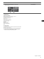
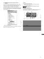
3.3 Locating virtual COM port number
3.4 Connectors
To use the virtual COM port from a PC tool, the number assigned
to the virtual COM port is needed. This information can be found
from the Device Manager in Windows.
The PC Tool Link is supplied with two connectors:
•
15-pole SubD female connector (connects to the Grundfos
product)
Control panel > System > Hardware > Device Manager.
•
USB connector (connects to the PC).
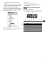
In the Device Manager, expand the "Ports (COM & LPT)" item,
and locate the "USB Serial Port" item. The virtual COM port
number will appear in brackets next to the name, e.g. USB Serial
Port (COM4) as highlighted in fig. 2.
If the communication fails,
see section 6. Fault finding.
Note
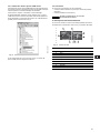
4. Functional description
The PC Tool Link has nine indicator lights (LEDs) for indication of
the status of communication between the PC and the Grundfos
product.
2
Data
1
USB
TM04 4192 1009
3
Fig. 2
Device Manager
If more than one PC Tool Link are connected to the PC, a virtual
COM port number will be assigned to each unit.
Fig. 3
Pos.
PC Tool Link
Grundfos Unit
Data
6
RS232
TTL
GENIbus
(RS485)
Power
5
9
8
7
TM03 9311 3707
PC
3 kV Galvanic Isolation
4
LED colours
Colour of LED
1
Orange
2
Red
3
Red
4
Red
5
Red
6
Yellow
7
Yellow
8
Yellow
9
Green
5
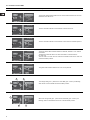
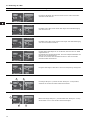
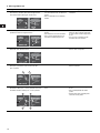
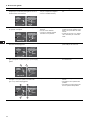
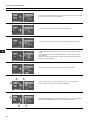
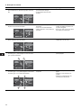
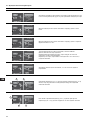
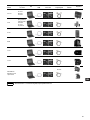
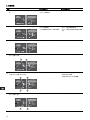
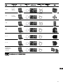
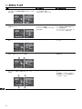
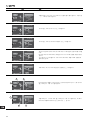
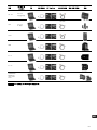
4.1 Functions of the LEDs
Illustration
Description
PC
Data
USB
3 kV Galvanic Isolation
1
PC Tool Link
Grundfos Unit
Data
RS232
TTL
The orange LED is flashing when the PC communicates with the PC Tool Link.
Otherwise, the LED is off.
GENIbus
(RS485)
Power
PC
Data
USB
3 kV Galvanic Isolation
2
PC Tool Link
Grundfos Unit
Data
RS232
The two red LEDs indicate communication to and from the PC.
TTL
GENIbus
(RS485)
Power
PC
Data
USB
3 kV Galvanic Isolation
3
PC Tool Link
Grundfos Unit
Data
RS232
The two red LEDs indicate communication to and from the Grundfos product.
TTL
GENIbus
(RS485)
Power
PC
Data
USB
3 kV Galvanic Isolation
4
PC Tool Link
Grundfos Unit
Data
RS232
TTL
GENIbus
(RS485)
The three yellow LEDs indicate whether an RS-232, RS-485 or TTL cable is
connected.
The RS-232 or RS-485 LED is on when the cable is connected to the
PC Tool Link.
The TTL LED is on when the TTL cable is connected to both the PC Tool Link
and the Grundfos product.
Power
PC
Data
USB
3 kV Galvanic Isolation
5
PC Tool Link
Grundfos Unit
Data
RS232
The green LED indicates that the PC Tool Link is powered.
TTL
GENIbus
(RS485)
Power
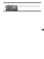
6
1
PC
Data
USB
3 kV Galvanic Isolation
3
2
PC Tool Link
Grundfos Unit
Data
RS232
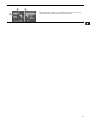
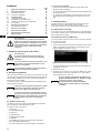
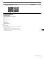
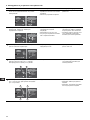
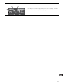
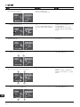
The orange LED (pos. 1) and the four red LEDs (pos. 2 and 3) are flashing
while the PC communicates with the Grundfos product.
TTL
GENIbus
(RS485)
Power
1
PC
Data
USB
2
6
3 kV Galvanic Isolation
7
PC Tool Link
Grundfos Unit
Data
RS232
TTL
GENIbus
(RS485)
Power
3
When the orange LED (pos. 1) and the two red LEDs (pos. 2 and 3) are
flashing, data is transmitted from the PC to the Grundfos product.
8
1
3
PC
Data
USB
3 kV Galvanic Isolation
2
PC Tool Link
Grundfos Unit
Data
When the orange LED (pos. 1) and the two red LEDs (pos. 2 and 3) are
flashing, data is transmitted from the Grundfos product to the PC.
RS232
TTL
GENIbus
(RS485)
Power
7
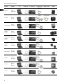
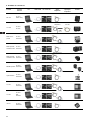
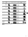
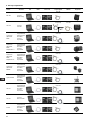
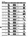
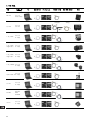
5. Connection overview
Product
PC Tool
software
PC
USB cable
PC Tool Link
Adapter cable
Productspecific cable
RS-485
MP 204
PC Tool
Water Utility
RS-232 and
adapter
CU 300
PC Tool
CU 300
RS-485 or TTL
1-phase MGE
PC Tool
E-products
RS-485
3-phase MGE,
models
B and C
PC Tool
E-products
RS-485 or TTL
3-phase MGE,
models
D and F
PC Tool
E-products
RS-485 or TTL
3-phase
MMGE
PC Tool
E-products
RS-485
Hydro Multi-E
PC Tool
E-products
RS-485 or TTL
CU 351
PC Tool
E-products
RS-485 or TTL
CU 361
PC Tool
WW
Controls
RS-485
IO 351
8
PC Tool
E-products
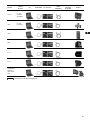
* CU 300 cable
Product
PC Tool
software
Product
PC
USB cable
PC Tool Link
Adapter cable
Productspecific cable
Product
RS-232
PC Tool
Modular
Controls
CU 401
RS-485
PC Tool
E-products
CUE
RS-232
PC Tool
G100
G100
RS-485
DME
RS-485
IO 111
RS-485
IO 112
RS-485
GRUNDFOS
MAGNA and
UPE Series
2000
Note
* Supplied with the corresponding PC tool.
9
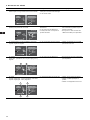
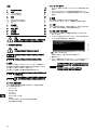
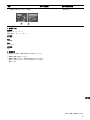
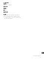
6. Fault finding
Problem
Possible cause
Suggested action
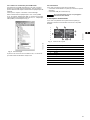
1 Communication has been established. The green
LED goes out after a long time without
communication.
• The PC has suspended the PC Tool
Link for power saving.
• The PC is in standby mode.
• Resume normal PC mode.
• The product-specific cable is
defective.
• The PC Tool Link is defective.
• The 5-volt output from the Grundfos
product is missing.
• Check that the product-specific
cable has been connected to the
product and that the product has
been switched on.
• Send the PC Tool Link with cables
to Grundfos for service.
• The PC is not transmitting.
• Check the COM port settings for
the PC Tool Link.
• The PC Tool Link is defective.
• Send the PC Tool Link to Grundfos
for service.
• The Grundfos product is not
responding.
• Check that the product has been
switched on.
• Check the product-specific cable.
• Check the configuration of the
product-specific PC tool.
Data
USB
PC Tool Link
3 kV Galvanic Isolation
PC
Grundfos Unit
Data
RS232
TTL
GENIbus
(RS485)
Power
PC
Data
USB
3 kV Galvanic Isolation
2 None of the yellow LEDs are on. The productspecific cable is connected.
PC Tool Link
Grundfos Unit
Data
RS232
TTL
GENIbus
(RS485)
Power
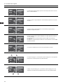
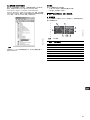
3 Communication has not been established. None of
the red LEDs are flashing.
Data
USB
PC Tool Link
3 kV Galvanic Isolation
PC
Grundfos Unit
Data
RS232
TTL
GENIbus
(RS485)
Power
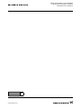
4 Communication has not been established. The red
LED (pos. 1) is off, and the red LED (pos. 2) is
flashing.
1
2
Data
USB
PC Tool Link
3 kV Galvanic Isolation
PC
Grundfos Unit
Data
RS232
TTL
GENIbus
(RS485)
Power
5 Communication has not been established. Two red
LEDs (pos. 1 and 2) are off, and two red LEDs
(pos. 3 and 4) are flashing.
2
PC
Data
USB
3
10
PC Tool Link
3 kV Galvanic Isolation
1
Grundfos Unit
Data
RS232
TTL
GENIbus
(RS485)
Power
4
Problem
PC
Data
USB
1
Possible cause
Suggested action
• The PC Tool Link is defective.
• Send the PC Tool Link to Grundfos
for service.
PC Tool Link
3 kV Galvanic Isolation
6
Communication has not been established. One red
LED (pos. 1) is flashing, and one red LED (pos. 2)
is off.
Grundfos Unit
Data
RS232
TTL
GENIbus
(RS485)
Power
2
7. Technical data
Ambient temperature
During operation: –10 °C to +50 °C
During storage: –20 °C to +60 °C.
Relative air humidity
Maximum 95 %.
Power supply
USB connection.
Current
Maximum 250 mA.
Enclosure class
IP20.
8. Disposal
This product or parts of it must be disposed of in an
environmentally sound way:
1. Use the public or private waste collection service.
2. If this is not possible, contact the nearest Grundfos company
or service workshop.
Subject to alterations.
11
INHALTSVERZEICHNIS
2.1 Das Paket PC Tool Link
Seite
1.
Kennzeichnung von Hinweisen
12
Das Paket PC Tool Link enthält alle Komponenten, die zum
Anschluss eines Grundfos Produkts an einen PC erforderlich
sind.
2.
Allgemeine Beschreibung
2.1
Das Paket PC Tool Link
2.1.1 Inhalt der CD-ROM
12
12
12
3.
3.1
3.2
3.3
3.4
Kommunikation
Spannungsversorgung
Installieren des virtuellen COM-Ports
Auffinden der Nummer des virtuellen COM-Ports
Anschlüsse
12
12
13
13
13
4.
4.1
Funktionsbeschreibung
Bedeutung der LEDs
13
14
5.
Verbindungsübersicht
16
6.
Störungsübersicht
18
7.
Technische Daten
19
2.1.1 Inhalt der CD-ROM
8.
Entsorgung
19
•
setup.exe ist die Installationsdatei zum Installieren des virtuellen COM-Ports (ab Windows 2000 und spätere Versionen).
•
PC Tool link.pdf ist eine PDF-Datei mit der vorliegenden Montage- und Betriebsanleitung.
•
Der Ordner "Development" enthält die Dokumentation und
Programme, die zur Herstellung einer direkten Verbindung
zum PC Tool Link erforderlich sind.
Warnung
Diese Montage- und Betriebsanleitung enthält
grundlegende Hinweise, die bei der Montage und
dem Betrieb der Pumpe zu beachten sind. Sie ist
daher unbedingt vor der Montage und Inbetriebnahme vom Monteur sorgfältig durchzulesen.
Weiterhin sind die bestehenden nationalen Vorschriften zu beachten.
1. Kennzeichnung von Hinweisen
Der PC Tool Link-Koffer enthält:
•
PC Tool Link
•
Standard-USB-Kabel
•
TTL-Kabel
•
RS-485-Kabel
•
RS-232-Kabel (verdrillt)
•
Adapter
•
CD-ROM mit Programm zum Einrichten des virtuellen
COM-Ports und mit der Montage- und Betriebsanleitung
•
Druckversion der Montage- und Betriebsanleitung.
3. Kommunikation
Grundfos verwendet generell drei Arten von elektrischen Schnittstellen zur Kommunikation mit seinen Produkten:
RS-485, RS-232 und TTL. Deshalb wird das PC Tool Link mit drei
entsprechenden Kabeln ausgeliefert.
Warnung
Die in dieser Montage- und Betriebsanleitung
enthaltenen Sicherheitshinweise, die bei
Nichtbeachtung Gefährdungen für Personen
hervorrufen können, sind mit dem allgemeinen
Gefahrensymbol "Sicherheitszeichen nach
DIN 4844-W00" besonders gekennzeichnet.
Achtung
Dieses Symbol finden Sie bei Sicherheitshinweisen, deren Nichtbeachtung Gefahren für
die Maschine und deren Funktionen hervorrufen
kann.
Hinweis
Hier stehen Ratschläge oder Hinweise, die das
Arbeiten erleichtern und für einen sicheren
Betrieb sorgen.
2. Allgemeine Beschreibung
Das Grundfos PC Tool Link ist eine Kommunikationsplattform,
über die alle Grundfos Produkte mit integrierter Kommunikationsschnittstelle an einen PC angeschlossen werden können, auf
dem ein produktspezifisches Grundfos PC Tool installiert ist.
Das Grundfos PC Tool Link bildet die dritte Generation von
Grundfos Kommunikationsadaptern.
Hinweis
Das PC Tool Link kann nicht in Verbindung mit
Grundfos Produkten verwendet werden, die über
ein Stromkabel kommunizieren.
Hinweis
Das PC Tool gewährleistet eine galvanische
Trennung zwischen dem PC und dem angeschlossenen Produkt. Falls zwischen den miteinander verbundenen Geräten eine Potentialdifferenz besteht, wird zudem eine Beschädigung
der Geräte verhindert.
12
3.1 Spannungsversorgung
Das PC Tool Link verfügt über keine eigene Spannungsversorgung. Es wird vom USB-Anschluss am PC mit Strom versorgt.
Wird ein USB-Hub verwendet, muss dieser über eine eigene
Spannungsquelle verfügen (self-powered).
3.2 Installieren des virtuellen COM-Ports
3.4 Anschlüsse
Die Kommunikation zwischen dem PC Tool und dem PC Tool Link
wird über einen virtuellen COM-Port aufgebaut.
Das Gerät PC Tool Link ist mit zwei Anschlüssen ausgestattet:
•
15-polige SubD-Anschlussbuchse (für die Verbindung zum
Grundfos Produkt)
•
USB-Anschluss (zum Anschluss an den PC).
1. Die CD-ROM einlegen.
2. Die Datei setup.exe aus dem Verzeichnis der CD-ROM aus
aufrufen. Es öffnet sich kurz ein Fenster, in dem eine Befehlszeile mit der Nachricht angezeigt wird, dass der Treiber installiert wird. Siehe Abb. 1.
Hinweis
Falls keine Kommunikation aufgebaut wird, siehe
Abschnitt 6. Störungsübersicht.
Das PC Tool Link verfügt über neun Meldeleuchten (LEDs) zur
Anzeige des Kommunikationsstatus zwischen dem PC und dem
Grundfos Produkt.
2
4
PC
Data
Nach dem automatischen Schließen des Fensters wurden alle
erforderlichen Dateien auf dem PC installiert.
1
USB
3. Den PC neu starten.
4. Das Gerät PC Tool Link über einen USB-Anschluss an den PC
anschließen. Die neue Hardware wird von Windows automatisch erkannt und dem PC Tool Link wird ein virtueller COMPort zugewiesen.
Hinweis
Wird ein anderes Betriebssystem als Windows
2000/XP/Vista/Server 2003/Server 2008 verwendet, kann der passende Treiber unter
http://www.ftdichip.com/Drivers/VCP.htm
gefunden werden (einen VCP-Treiber für das
Gerät "FT232R" wählen).
3
6
RS232
TTL
GENIbus
(RS485)
Power
5
9
8
7
Farbe des LED
1
orange
2
rot
3
rot
3.3 Auffinden der Nummer des virtuellen COM-Ports
4
rot
Um den virtuellen COM-Port vom PC Tool aus nutzen zu können,
wird die dem virtuellen COM-Port zugewiesene Nummer benötigt.
Die entsprechenden Angaben können dem Gerätemanager in
Windows entommen werden.
5
rot
6
gelb
7
gelb
8
gelb
9
grün
TM04 4192 1009
Im Gerätemanager das Verzeichnis "Ports (COM & LPT)" erweitern, so dass das Unterverzeichnis "USB Serial Port" sichtbar
wird. Die Zuordnungsnummer des COM-Ports wird in Klammern
neben der Bezeichnung angezeigt, z.B. USB Serial Port (COM4)
wie in Abb. 2 hervorgehoben.
Data
Abb. 3 Farbzuordnung der LED
Pos.
Control panel > System > Hardware > Device Manager.
PC Tool Link
Grundfos Unit
TM03 9311 3707
Abb. 1 Installieren des virtuellen COM-Ports
3 kV Galvanic Isolation
TM04 4193 1009
4. Funktionsbeschreibung
Abb. 2 Device Manager
Ist mehr als ein PC Tool Link an den PC angeschlossen, wird
jedem einzelnen Gerät eine eigene COM-Portnummer zugewiesen.
13
4.1 Bedeutung der LEDs
Abbildung
Beschreibung
PC
Data
USB
3 kV Galvanic Isolation
1
PC Tool Link
Grundfos Unit
Data
RS232
TTL
Die orange LED blinkt, wenn der PC mit dem PC Tool Link kommuniziert.
Ansonsten ist die LED aus.
GENIbus
(RS485)
Power
PC
Data
USB
3 kV Galvanic Isolation
2
PC Tool Link
Grundfos Unit
Data
RS232
TTL
Die beiden roten LEDs auf der linken Seite zeigen eine Datenübertragung
vom und zum PC an.
GENIbus
(RS485)
Power
PC
Data
USB
3 kV Galvanic Isolation
3
PC Tool Link
Grundfos Unit
Data
RS232
TTL
Die beiden roten LEDs auf der rechten Seite zeigen eine Datenübertragung
vom und zum Grundos Produkt an.
GENIbus
(RS485)
Power
PC
Data
USB
3 kV Galvanic Isolation
4
PC Tool Link
Grundfos Unit
Data
RS232
TTL
GENIbus
(RS485)
Die drei gelben LEDs zeigen an, ob ein RS-232-, RS-485- oder TTL-Kabel
angeschlossen ist.
Die LED RS-232 oder RS-485 leuchtet, wenn das entsprechende Kabel mit
dem PC Tool Link verbunden ist.
Die LED TTL leuchtet, wenn das Kabel mit dem PC Tool Link und dem
Grundfos Produkt verbunden ist.
Power
PC
Data
USB
3 kV Galvanic Isolation
5
PC Tool Link
Grundfos Unit
Data
RS232
Die grüne LED zeigt an, dass das PC Tool Link mit Spannung versorgt wird.
TTL
GENIbus
(RS485)
Power
6
1
PC
Data
USB
3 kV Galvanic Isolation
3
2
PC Tool Link
Grundfos Unit
Data
RS232
Die orange LED (Pos. 1) und die vier roten LEDs (Pos. 2 und 3) blinken,
sobald der PC mit dem Grundfos Produkt kommuniziert.
TTL
GENIbus
(RS485)
Power
1
PC
Data
USB
2
14
3 kV Galvanic Isolation
7
PC Tool Link
Grundfos Unit
Data
RS232
TTL
GENIbus
(RS485)
Power
3
Blinken die orange LED (Pos. 1) und die beiden roten LEDs (Pos. 2 und 3)
werden Daten vom PC zum Grundfos Produkt übertragen.
8
1
3
PC
Data
USB
3 kV Galvanic Isolation
2
PC Tool Link
Grundfos Unit
Data
Blinken die orange LED (Pos. 1) und die beiden roten LEDs (Pos. 2 und 3)
werden Daten vom Grundfos Produkt zum PC übertragen.
RS232
TTL
GENIbus
(RS485)
Power
15
5. Verbindungsübersicht
Produkt
PC Tool
Programm
PC
USBKabel
PC Tool Link
Adapterkabel
Produktspezifisches
Kabel
RS-485
MP 204
PC Tool
Water Utility
RS-232 und
Adapter
CU 300
PC Tool
CU 300
RS-485 oder TTL
1-phasige
MGE-Motoren
PC Tool
E-Produkte
RS-485
3-phasige
MGE-Motoren, PC Tool
E-Produkte
Modelle
B und C
RS-485 oder TTL
3-phasige
MGE-Motoren, PC Tool
E-Produkte
Modelle
D und F
RS-485 oder TTL
3-phasige
MMGEMotoren
PC Tool
E-Produkte
RS-485
Hydro Multi-E
PC Tool
E-Produkte
RS-485 oder TTL
CU 351
PC Tool
E-Produkte
RS-485 oder TTL
CU 361
PC Tool
WW
Controls
RS-485
IO 351
16
PC Tool
E-Produkte
* CU 300Kabel
Produkt
PC Tool
Programm
Produkt
PC
USBKabel
PC Tool Link
Adapterkabel
Produktspezifisches
Kabel
Produkt
RS-232
PC Tool
Modular
Controls
CU 401
RS-485
PC Tool
E-Produkte
CUE
RS-232
G100
RS-485
DME
RS-485
IO 111
RS-485
IO 112
RS-485
GRUNDFOS
MAGNA und
UPE Serie
2000
Hinweis
* Im Lieferumfang des entsprechenden PC Tools enthalten.
17
6. Störungsübersicht
Störung
Mögliche Ursache
1 Die Kommunikation wurde aufgebaut. Die grüne
LED erlischt, nachdem über einen längeren Zeitraum keine Daten übertragen worden sind.
• Normalen PC-Modus wieder• Der PC hat die Verbindung zum
herstellen.
PC Tool unterbrochen, um Strom zu
sparen.
• Der PC befindet sich im StandbyModus.
Data
USB
PC Tool Link
3 kV Galvanic Isolation
PC
Grundfos Unit
Data
RS232
TTL
GENIbus
(RS485)
Power
Data
USB
3 kV Galvanic Isolation
2 Keine der gelben LEDs leuchtet. Das produktspezifische Kabel ist angeschlossen.
PC
PC Tool Link
Grundfos Unit
Data
Data
• Das PC Tool Link an den Grundfos
Service schicken.
• Das Grundfos Produkt antwortet
nicht.
• Prüfen, ob das Produkt eingeschaltet ist.
• Das produktspezifische Kabel
prüfen.
• Konfiguration des produktspezifischen PC-Tools prüfen.
RS232
TTL
GENIbus
(RS485)
Power
PC Tool Link
Grundfos Unit
Data
RS232
TTL
GENIbus
(RS485)
Power
5 Es wurde keine Kommunikation aufgebaut.
Die beiden LEDs (Pos. 1 und 2) leuchten nicht und
die beiden anderen LEDs (Pos. 3 und 4) blinken.
2
PC
Data
PC Tool Link
3 kV Galvanic Isolation
1
18
• Das Gerät PC Tool Link ist defekt.
Power
Grundfos Unit
3 kV Galvanic Isolation
Data
USB
3
• Die COM-Port Einstellungen für
das PC Tool Link prüfen.
GENIbus
(RS485)
2
PC
USB
• Der PC überträgt keine Daten.
RS232
4 Es wurde keine Kommunikation aufgebaut. Die rote
LED (Pos. 1) leuchtet nicht und die rote LED
(Pos. 2) blinkt.
1
• Prüfen, ob das produktspezifische
Kabel mit dem Produkt verbunden
ist und ob das Produkt eingeschaltet ist.
• PC Tool Link und Kabel an den
Grundfos Service schicken.
PC Tool Link
3 kV Galvanic Isolation
Data
USB
• Das produktspezifische Kabel ist
defekt.
• Das Gerät PC Tool Link ist defekt.
• Das 5 Volt-Ausgangssignal vom
Grundfos Produkt liegt nicht an.
TTL
3 Es wurde keine Kommunikation aufgebaut.
Keine der roten LEDs leuchtet.
PC
Abhilfevorschlag
Grundfos Unit
Data
RS232
TTL
GENIbus
(RS485)
Power
4
Störung
PC
Data
USB
1
Mögliche Ursache
Abhilfevorschlag
• Das Gerät PC Tool Link ist defekt.
• Das PC Tool Link an den Grundfos
Service schicken.
PC Tool Link
3 kV Galvanic Isolation
6
Es wurde keine Kommunikation aufgebaut. Die eine
LED (Pos. 1) blinkt und die andere LED (Pos. 2)
leuchtet nicht.
Grundfos Unit
Data
RS232
TTL
GENIbus
(RS485)
Power
2
7. Technische Daten
Umgebungstemperatur
Während des Betriebs: –10 °C bis +50 °C
Während der Lagerung: –20 °C bis +60 °C.
Relative Luftfeuchtigkeit
Max. 95 %.
Spannungsversorgung
USB-Anschluss.
Strom
Max. 250 mA.
Schutzart
IP20.
8. Entsorgung
Dieses Produkt sowie Teile davon müssen umweltgerecht entsorgt werden:
1. Nutzen Sie die öffentlichen oder privaten Entsorgungsgesellschaften.
2. Ist das nicht möglich, wenden Sie sich bitte an die nächste
Grundfos Gesellschaft oder Werkstatt.
Technische Änderungen vorbehalten.
19
SOMMAIRE
2.1.1 Contenu du CD-ROM
Page
1.
Symboles utilisés dans cette notice
•
setup.exe est le fichier d'installation du port COM virtuel
(Windows 2000 et ultérieur).
•
PC Tool link.pdf est le fichier PDF de la notice d'installation et
de fonctionnement.
•
Le dossier de programmation contient des informations pour
les programmeurs voulant établir un lien direct au PC Tool
Link.
20
2.
Description générale
2.1
Coffret PC Tool Link
2.1.1 Contenu du CD-ROM
20
20
20
3.
3.1
3.2
3.3
3.4
Communication
Alimentation électrique
Installation du port COM virtuel
Localiser le numéro du port COM virtuel
Connecteurs
20
20
20
21
21
4.
4.1
Description fonctionnelle
Fonctions des voyants
21
22
5.
Schéma de connexion
24
6.
Recherche des défauts
26
7.
Caractéristiques techniques
27
8.
Mise au rebut
27
3. Communication
Grundfos utilise trois types d'interfaces électriques, RS-485,
RS-232 et TTL pour communiquer avec un produit.
Le PC Tool Link est fourni avec trois câbles correspondants.
3.1 Alimentation électrique
Le PC Tool Link n'a pas d'alimentation interne. Il est alimenté via
le connecteur USB sur le PC. Si une plate-forme USB est utilisée,
elle doit être auto-alimentée.
Avertissement
3.2 Installation du port COM virtuel
Avant d'entamer les opérations d'installation,
étudier avec attention la présente notice d'installation et d'entretien. L'installation et le fonctionnement doivent être conformes aux réglementations locales et faire l'objet d'une bonne
utilisation.
La communication entre un PC tool et un PC Tool Link s'effectue
via un port COM virtuel.
1. Insérer le CD-ROM.
2. Lancer le fichier setup.exe à partir du répertoire racine du CDROM. Une fenêtre de commande s'ouvre brièvement, indiquant l'installation du pilote. Voir fig. 1.
1. Symboles utilisés dans cette notice
TM04 4193 1009
Avertissement
Si ces instructions de sécurité ne sont pas
observées, il peut en résulter des dommages
corporels!
Si ces instructions ne sont pas respectées, cela
Précautions peut entraîner un dysfonctionnement ou des
dégâts sur le matériel!
Nota
Ces instructions rendent le travail plus facile et
assurent un fonctionnement fiable.
2. Description générale
Le PC Tool Link Grundfos est un outil de communication qui peut
connecter tous les produits Grundfos équipés d'une interface de
communication intégrée à un PC avec un produit Grundfos sur
lequel le PC Tool est installé.
Le PC Tool Link est la troisième génération des adaptateurs de
communication Grundfos.
Nota
Le PC Tool Link ne peut pas être utilisé en combinaison avec des produits Grundfos communiquant via un câble sur courant porteur.
Nota
Le PC Tool Link assure une séparation galvanique entre le PC et le produit connecté. Le risque
de dommages en cas de différence de potentiel
entre les unités connectées est également
éliminé.
2.1 Coffret PC Tool Link
Le coffret PC Tool Link contient tous les éléments nécessaires
pour connecter le produit Grundfos et le PC.
La valise PC Tool Link contient :
•
PC Tool Link
•
un câble USB standard
•
un câble TTL
•
un câble RS-485
•
un câble RS-232 (croisé)
•
un adapteur
•
un CD-ROM avec logiciel de communication virtuelle et
notice d'installation et d'entretien
•
une version papier de la notice d'installation et d'entretien.
20
Fig. 1
Installation du port COM virtuel
Lorsque la fenêtre disparaît, tous les fichiers nécessaires ont
été installés sur le PC.
3. Redémarrer le PC.
4. Connecter le PC Tool Link à un autre port USB du PC. Il sera
automatiquement reconnu par Windows, et un port COM virtuel est attribué au PC Tool Link.
Nota
Si votre système d'exploitation est différent de
Windows 2000/XP/Vista/Server 2003/Server 2008,
vous pouvez trouver le bon pilote à :
http://www.ftdichip.com/Drivers/VCP.htm
(sélectionner un pilote VCP pour le dispositif
"FT232R").
3.3 Localiser le numéro du port COM virtuel
3.4 Connecteurs
Pour utiliser le port COM virtuel depuis un PC tool, le numéro
attribué au port COM virtuel est nécessaire. Ces informations
peuvent être trouvées depuis le Gestionnaire de périphériques de
Windows.
Le PC Tool Link est fourni avec deux connecteurs :
•
Connecteur femelle SubD à 15 pôles (se connecte au produit
Grundfos)
•
Connecteur USB (se connecte au PC).
Control panel > System > Hardware > Device Manager.
Dans le Gestionnaire de périphériques, ouvrir "Ports (COM &
LPT)", et localiser "Périphérique USB". Le numéro du port COM
virtuel apparaît entre guillemets à côté du nom, ex. : Périphérique
USB (COM4) comme indiqué à la fig. 2.
Si la communication échoue, voir paragraphe
6. Recherche des défauts.
Nota
4. Description fonctionnelle
Le PC Tool Link possède neuf voyants lumineux (LED) qui
indiquent le statut de communication entre le PC et le produit
Grundfos.
2
Data
1
USB
TM04 4192 1009
3
Fig. 2
Device Manager
Si plus d'un PC Tool Link sont connectés au PC, un numéro de
port COM virtuel est attribué à chaque unité.
Fig. 3
Couleurs des voyants
Pos.
Couleur du voyant
1
Orange
2
Rouge
3
Rouge
4
Rouge
5
Rouge
6
Jaune
7
Jaune
8
Jaune
9
Vert
PC Tool Link
Grundfos Unit
Data
6
RS232
TTL
GENIbus
(RS485)
Power
5
9
8
7
TM03 9311 3707
PC
3 kV Galvanic Isolation
4
21
4.1 Fonctions des voyants
Illustration
Description
PC
Data
USB
3 kV Galvanic Isolation
1
PC Tool Link
Grundfos Unit
Data
RS232
TTL
La LED orange clignote lorsque que le PC communique avec le PC Tool Link.
Sinon, la LED est éteinte.
GENIbus
(RS485)
Power
PC
Data
USB
3 kV Galvanic Isolation
2
PC Tool Link
Grundfos Unit
Data
RS232
TTL
Les deux voyants rouges indiquent la communication jusqu'au PC ou à partir
de celui-ci.
GENIbus
(RS485)
Power
PC
Data
USB
3 kV Galvanic Isolation
3
PC Tool Link
Grundfos Unit
Data
RS232
TTL
Les deux voyants rouges indiquent la communication jusqu'au produit
Grundfos ou à partir de celui-ci.
GENIbus
(RS485)
Power
PC
Data
USB
3 kV Galvanic Isolation
4
PC Tool Link
Grundfos Unit
Data
RS232
TTL
GENIbus
(RS485)
Les trois voyants lumineux jaunes indiquent si un câble RS-232, RS-485 ou
TTL est connecté.
Le voyant RS-232 ou RS-485 s'allume lorsque le câble est connecté au
PC Tool Link.
Le voyant TTL s'allume lorsque le câble TTL est connecté au PC Tool Link ET
au produit Grundfos.
Power
PC
Data
USB
3 kV Galvanic Isolation
5
PC Tool Link
Grundfos Unit
Data
RS232
Le voyant vert indique que le PC Tool Link est branché au secteur.
TTL
GENIbus
(RS485)
Power
6
1
PC
Data
USB
3 kV Galvanic Isolation
3
2
PC Tool Link
Grundfos Unit
Data
RS232
Le voyant orange (pos. 1) et les quatre voyants rouges (pos. 2 et 3) clignotent
lorsque le PC communique avec le produit Grundfos.
TTL
GENIbus
(RS485)
Power
1
PC
Data
USB
2
22
3 kV Galvanic Isolation
7
PC Tool Link
Grundfos Unit
Data
RS232
TTL
GENIbus
(RS485)
Power
3
Lorsque le voyant orange (pos. 1) et les deux voyants rouges (pos. 2 et 3)
clignotent, les données sont transmises entre le PC et le produit Grundfos.
8
1
3
PC
Data
USB
3 kV Galvanic Isolation
2
PC Tool Link
Grundfos Unit
Data
Lorsque le voyant orange (pos. 1) et les deux voyants rouges (pos. 2 et 3)
clignotent, les données sont transmises du produit Grundfos au PC.
RS232
TTL
GENIbus
(RS485)
Power
23
5. Schéma de connexion
Produit
Logiciel
PC Tool
PC
Câble USB
PC Tool Link
Câble
adaptateur
Câble
spécifique
au produit
RS-485
MP 204
PC Tool
Water Utility
RS-232 et
adaptateur
CU 300
PC Tool
CU 300
RS-485 ou TTL
MGE monophasé
PC Tool
Produits E
RS-485
MGE triphasé, PC Tool
modèles B et C Produits E
RS-485 ou TTL
MGE triphasé, PC Tool
modèles D et F Produits E
RS-485 ou TTL
MMGE triphasé
PC Tool
Produits E
RS-485
Hydro Multi-E
PC Tool
Produits E
RS-485 ou TTL
CU 351
PC Tool
Produits E
RS-485 ou TTL
CU 361
PC Tool
WW
Controls
RS-485
IO 351
24
PC Tool
Produits E
* Câble
CU 300
Produit
Logiciel
PC Tool
Produit
PC
Câble USB
PC Tool Link
Câble
adaptateur
Câble
spécifique
au produit
Produit
RS-232
PC Tool
Contrôles
modulaires
CU 401
RS-485
PC Tool
Produits E
CUE
RS-232
G100
RS-485
DME
RS-485
IO 111
RS-485
IO 112
RS-485
GRUNDFOS
MAGNA et
UPE Series
2000
Nota
* Fourni avec le PC tool correspondant.
25
6. Recherche des défauts
Problème
Cause possible
Solution proposée
• Le PC a mis le PC Tool Link en
• Revenir au mode PC normal.
1 La communication a été établie. La LED verte
s'éteint après un long moment sans communication.
veille pour une économie d'énergie.
• Le PC est en veille.
Data
USB
PC Tool Link
3 kV Galvanic Isolation
PC
Grundfos Unit
Data
RS232
TTL
GENIbus
(RS485)
Power
PC
Data
USB
3 kV Galvanic Isolation
2 Aucun des voyants jaunes n'est allumé. Le câble
spécifique au produit est connecté.
PC Tool Link
Grundfos Unit
Data
RS232
GENIbus
(RS485)
Power
USB
Grundfos Unit
Data
RS232
TTL
GENIbus
(RS485)
Power
4 La communication n'a pas été établie. Le voyant
rouge (pos. 1) est éteint, et le voyant rouge (pos. 2)
clignote.
1
USB
Grundfos Unit
Data
RS232
TTL
GENIbus
(RS485)
Power
5 La communication n'a pas été établie. Les deux
voyants rouges (pos. 1 et 2) sont éteints, et les deux
voyants rouges (pos. 3 et 4) clignotent.
2
PC
Data
PC Tool Link
3 kV Galvanic Isolation
1
26
• Envoyer le PC Tool Link à Grundfos
pour réparation.
PC Tool Link
3 kV Galvanic Isolation
Data
3
• Le PC Tool Link est défectueux.
2
PC
USB
• Le PC ne transmet aucune donnée. • Vérifier les réglages du port COM
pour le PC Tool Link.
PC Tool Link
3 kV Galvanic Isolation
Data
• Vérifier que le câble spécifique est
bien connecté au produit et que ce
dernier est allumé.
• Envoyer le PC Tool Link avec les
câbles à Grundfos pour réparation.
TTL
3 La communication n'a pas été établie. Aucun des
voyants rouges ne clignote.
PC
• Le câble spécifique au produit est
défectueux.
• Le PC Tool Link est défectueux.
• Il manque la sortie 5 V à partir du
produit Grundfos.
Grundfos Unit
Data
RS232
TTL
GENIbus
(RS485)
Power
4
• Le produit Grundfos ne répond pas. • Vérifier que le produit est allumé.
• Vérifier le câble spécifique au
produit.
• Vérifier la configuration du PC tool.
Problème
PC
Data
USB
1
Cause possible
Solution proposée
• Le PC Tool Link est défectueux.
• Envoyer le PC Tool Link à Grundfos
pour réparation.
PC Tool Link
3 kV Galvanic Isolation
6
La communication n'a pas été établie. Le voyant
rouge (pos. 1) clignote, et le voyant rouge (pos. 2)
est éteint.
Grundfos Unit
Data
RS232
TTL
GENIbus
(RS485)
Power
2
7. Caractéristiques techniques
Température ambiante
Pendant le fonctionnement : –10 °C à +50 °C
Pendant le stockage : –20 °C à +60 °C.
Humidité relative de l'air
Maximum 95 %.
Tension d'alimentation
Connexion USB.
Intensité
250 mA maxi.
Indice de protection
IP20.
8. Mise au rebut
Ce produit ou des parties de celui-ci doit être mis au rebut tout en
préservant l'environnement :
1. Utiliser le service local public ou privé de collecte des déchets.
2. Si ce n'est pas possible, envoyer ce produit à Grundfos ou au
réparateur agréé Grundfos le plus proche.
Nous nous réservons tout droit de modifications.
27
INDICE
2.1.1 Contenuti del CD-ROM
Pagina
1.
Simboli utilizzati in questo documento
•
setup.exe è il file eseguibile per l'installazione di una porta
COM virtuale (Windows 2000 e versioni successive).
•
PC Tool link.pdf è un file PDF delle presenti istruzioni di installazione e funzionamento.
•
La cartella di sviluppo contiene alcune informazioni destinate
agli sviluppatori che desiderano stabilire un collegamento
diretto con il PC Tool Link.
28
2.
Descrizione generale
2.1
Pacchetto PC Tool Link
2.1.1 Contenuti del CD-ROM
28
28
28
3.
3.1
3.2
3.3
3.4
Comunicazione
Alimentazione
Installazione della porta COM virtuale
Identificazione del numero della porta COM virtuale
Connettori
28
28
28
29
29
4.
4.1
Descrizione funzionale
Funzioni dei LED
29
30
5.
Panoramica dei collegamenti
32
6.
Ricerca dei guasti
34
7.
Dati tecnici
35
8.
Smaltimento
35
3. Comunicazione
Grundfos utilizza tre tipi di interfacce elettriche per la comunicazione con un prodotto, ovvero RS-485, RS-232 e TTL.
PC Tool Link viene fornito con tre cavi corrispondenti.
3.1 Alimentazione
PC Tool Link non dispone di alimentazione interna. Viene alimentato tramite il connettore USB sul PC. Se si utilizza un hub USB,
esso deve disporre di alimentazione autonoma.
Avvertimento
3.2 Installazione della porta COM virtuale
Prima dell'installazione leggere attentamente
le presenti istruzioni di installazione e funzionamento. Per il corretto montaggio e funzionamento, rispettare le disposizioni locali e
la pratica della regola d'arte.
La comunicazione tra uno strumento PC e un PC Tool Link viene
stabilita mediante una porta COM virtuale.
1. Simboli utilizzati in questo documento
1. Inserire il CD-ROM.
2. Lanciare il file setup.exe dalla directory root del CD-ROM.
Appare subito una finestra pop-up con una riga di comando
indicante che è in corso l'installazione del driver. Vedere la
fig. 1.
Avvertimento
Attenzione
La mancata osservanza di queste istruzioni
di sicurezza, può dare luogo a malfunzionamento
o danneggiare l'apparecchiatura!
Nota
Queste note o istruzioni rendono più semplice
il lavoro ed assicurano un funzionamento sicuro.
TM04 4193 1009
La mancata osservanza di queste istruzioni
di sicurezza, può dare luogo a infortuni!
Fig. 1
Installazione della porta COM virtuale
La scomparsa della finestra indica l'avvenuta installazione sul
PC di tutti i file necessari.
2. Descrizione generale
3. Riavviare il PC.
Grundfos PC Tool Link è un'unità di comunicazione che connette
tutti i prodotti Grundfos che integrano un'interfaccia di comunicazione con un PC su cui è installato un tool PC specifico per prodotto.
4. Collegare il PC Tool Link a una delle porte USB del PC.
Il PC Tool Link viene riconosciuto immediatamente da
Windows. Il sistema assegna una porta COM virtuale al
PC Tool Link.
Grundfos PC Tool Link costituisce la terza generazione di adattatori di comunicazione Grundfos.
Nota
PC Tool Link non si può utilizzare in combinazione con prodotti Grundfos che comunicano
tramite un cavo di potenza.
Nota
PC Tool Link garantisce una separazione galvanica tra il PC e il prodotto collegato. Il rischio di
danneggiamento in caso di differenza di potenziale tra le unità collegate è quindi eliminato.
2.1 Pacchetto PC Tool Link
Il pacchetto PC Tool Link include tutti gli elementi necessari per
collegare il prodotto Grundfos e il PC.
La valigetta di PC Tool Link contiene:
•
PC Tool Link
•
cavo USB standard
•
cavo TTL
•
cavo RS-485
•
cavo RS-232 (incrociato)
•
adattatore
•
CD-ROM con software porta COM virtuale, istruzioni di installazione e funzionamento
•
versione stampata delle istruzioni di installazione e funzionamento.
28
Nota
Per i PC che dispongono di un sistema operativo
diverso da Windows 2000/XP/Vista/Server 2003/
Server 2008, il driver corretto è disponibile
all'indirizzo
http://www.ftdichip.com/Drivers/VCP.htm
(selezionare un driver VCP per il dispositivo
"FT232R").
3.3 Identificazione del numero della porta COM
virtuale
3.4 Connettori
Per utilizzare la porta COM virtuale da PC Tool occorre identificare il numero assegnato alla porta COM virtuale. Queste informazioni sono reperibili tramite il menu "Gestione periferiche" di
Windows ("Gestione dispositivi" in Windows Vista).
•
connettore femmina SubD a 15 poli (per il collegamento al
prodotto Grundfos)
•
connettore USB (per il collegamento al PC).
PC Tool Link viene fornito con due connettori:
Se non si riesce a stabilire alcuna comunicazione, vedere sezione 6. Ricerca dei guasti.
Nota
4. Descrizione funzionale
PC Tool Link dispone di nove indicatori luminosi (LED) per segnalare lo stato della comunicazione tra il PC e il prodotto Grundfos.
2
4
PC
Data
1
USB
3
Fig. 3
TM04 4192 1009
Pos.
Fig. 2
Device Manager
Se al PC sono collegati più PC Tool LInk, a ogni unità viene assegnato un numero della porta COM virtuale.
PC Tool Link
Grundfos Unit
Data
6
RS232
TTL
GENIbus
(RS485)
Power
5
9
8
7
TM03 9311 3707
In Gestione periferiche ("Gestione dispositivi" in Windows Vista),
espandere la voce "Porte (COM e LPT)" e individuare la voce
"USB Serial Port". Il numero della porta COM virtuale appare tra
parentesi accanto al nome, ad es. "USB Serial Port (COM4)",
come evidenziato nella fig. 2.
3 kV Galvanic Isolation
Control panel > System > Hardware > Device Manager.
Colori dei LED
Colore del LED
1
Arancione
2
Rosso
3
Rosso
4
Rosso
5
Rosso
6
Giallo
7
Giallo
8
Giallo
9
Verde
29
4.1 Funzioni dei LED
Illustrazione
Descrizione
PC
Data
USB
3 kV Galvanic Isolation
1
PC Tool Link
Grundfos Unit
Data
RS232
TTL
Il LED arancione lampeggia quando il PC comunica con il PC Tool Link.
In caso contrario è spento.
GENIbus
(RS485)
Power
PC
Data
USB
3 kV Galvanic Isolation
2
PC Tool Link
Grundfos Unit
Data
RS232
I due LED rossi indicano la comunicazione da e verso il PC.
TTL
GENIbus
(RS485)
Power
PC
Data
USB
3 kV Galvanic Isolation
3
PC Tool Link
Grundfos Unit
Data
RS232
I due LED rossi indicano la comunicazione da e verso il prodotto Grundfos.
TTL
GENIbus
(RS485)
Power
PC
Data
USB
3 kV Galvanic Isolation
4
PC Tool Link
Grundfos Unit
Data
RS232
TTL
GENIbus
(RS485)
I tre LED gialli indicano se è collegato un cavo RS-232, RS-485 o TTL.
Il LED RS-232 o RS-485 è acceso se il cavo è collegato a PC Tool Link.
Il LED TTL è acceso se il cavo TTL è collegato sia a PC Tool Link che al
prodotto Grundfos.
Power
PC
Data
USB
3 kV Galvanic Isolation
5
PC Tool Link
Grundfos Unit
Data
RS232
Il LED verde indica che PC Tool Link è alimentato.
TTL
GENIbus
(RS485)
Power
6
1
PC
Data
USB
3 kV Galvanic Isolation
3
2
PC Tool Link
Grundfos Unit
Data
RS232
Il LED arancione (pos. 1) e i quattro LED rossi (pos. 2 e 3) lampeggiano
mentre il PC comunica con il prodotto Grundfos.
TTL
GENIbus
(RS485)
Power
1
PC
Data
USB
2
30
3 kV Galvanic Isolation
7
PC Tool Link
Grundfos Unit
Data
RS232
TTL
GENIbus
(RS485)
Power
3
Se il LED arancione (pos. 1) e i due LED rossi (pos. 2 e 3) lampeggiano,
è in corso la trasmissione dei dati dal PC al prodotto Grundfos.
8
1
3
PC
Data
USB
3 kV Galvanic Isolation
2
PC Tool Link
Grundfos Unit
Data
Se il LED arancione (pos. 1) e i due LED rossi (pos. 2 e 3) lampeggiano,
è in corso la trasmissione dei dati dal prodotto Grundfos al PC.
RS232
TTL
GENIbus
(RS485)
Power
31
5. Panoramica dei collegamenti
Prodotto
Software
Tool PC
PC
Cavo USB
PC Tool Link
Cavo adattatore
Cavo
specifico del
prodotto
RS-485
MP 204
PC Tool
Water Utility
RS-232 e
adattatore
CU 300
PC Tool
CU 300
RS-485 o TTL
MGE monofase
PC Tool
E-product
RS-485
MGE trifase,
modelli B e C
PC Tool
E-product
RS-485 o TTL
MGE trifase,
modelli D e F
PC Tool
E-product
RS-485 o TTL
MMGE trifase
PC Tool
E-product
RS-485
Hydro Multi-E
PC Tool
E-product
RS-485 o TTL
CU 351
PC Tool
E-product
RS-485 o TTL
CU 361
PC Tool
WW
Controls
RS-485
IO 351
32
PC Tool
E-product
* Cavo CU 300
Prodotto
Software
Tool PC
Prodotto
PC
Cavo USB
PC Tool Link
Cavo adattatore
Cavo
specifico del
prodotto
Prodotto
RS-232
PC Tool
Sistema di
Controllo
Modulare
CU 401
RS-485
PC Tool
E-product
CUE
RS-232
G100
RS-485
DME
RS-485
IO 111
RS-485
IO 112
RS-485
GRUNDFOS
MAGNA e serie
UPE 2000
Nota
* Fornito con il corrispondente PC tool.
33
6. Ricerca dei guasti
Problema
Possibile causa
Azione consigliata
1 La comunicazione è stata stabilita. Il LED verde si
spegne dopo un intervallo prolungato in cui non si
verifica alcuna comunicazione.
• Il PC ha messo in standby PC Tool
Link per il risparmio energetico
• Il PC è in modalità stand-by.
• Ripristinare la normale modalità
PC.
• Il cavo specifico del prodotto è
difettoso.
• PC Tool Link è difettoso.
• L'uscita a 5 Volt dal prodotto
Grundfos non è presente.
• Verificare che il cavo specifico del
prodotto sia stato collegato al prodotto e che quest'ultimo sia stato
acceso.
• Inviare PC Tool Link con i relativi
cavi a Grundfos per la manutenzione.
• Il PC non sta trasmettendo.
• Controllare le impostazioni della
porta COM per PC Tool Link.
Data
USB
PC Tool Link
3 kV Galvanic Isolation
PC
Grundfos Unit
Data
RS232
TTL
GENIbus
(RS485)
Power
PC
Data
USB
3 kV Galvanic Isolation
2 Nessuno dei LEd gialli è acceso. Il cavo specifico
del prodotto è collegato.
PC Tool Link
Grundfos Unit
Data
RS232
TTL
GENIbus
(RS485)
Power
3 La comunicazione non è stata stabilita. Nessuno dei
LED rossi sta lampeggiando.
Data
USB
PC Tool Link
3 kV Galvanic Isolation
PC
Grundfos Unit
Data
RS232
TTL
GENIbus
(RS485)
Power
4 La comunicazione non è stata stabilita. Il LED rosso • PC Tool Link è difettoso.
(pos. 1) è spento e il LED rosso (pos. 2) sta lampeggiando.
1
2
Data
USB
PC Tool Link
3 kV Galvanic Isolation
PC
Grundfos Unit
Data
RS232
TTL
GENIbus
(RS485)
Power
5 La comunicazione non è stata stabilita. Due LED
rossi (pos. 1 e 2) sono spenti e due LED rossi
(pos. 3 e 4) stanno lampeggiando.
2
PC
Data
3
34
PC Tool Link
3 kV Galvanic Isolation
1
USB
• Inviare PC Tool Link a Grundfos per
la manutenzione.
Grundfos Unit
Data
RS232
TTL
GENIbus
(RS485)
Power
4
• Il prodotto Grundfos non risponde.
• Verificare che il prodotto sia stato
acceso.
• Controllare il cavo specifico del
prodotto.
• Controllare la configurazione del
tool PC specifico del prodotto.
Problema
PC
Data
USB
1
Possibile causa
Azione consigliata
• PC Tool Link è difettoso.
• Inviare PC Tool Link a Grundfos per
la manutenzione.
PC Tool Link
3 kV Galvanic Isolation
6
La comunicazione non è stata stabilita. Un LED
rosso (pos. 1) sta lampeggiando e un LED rosso
(pos. 2) è spento.
Grundfos Unit
Data
RS232
TTL
GENIbus
(RS485)
Power
2
7. Dati tecnici
Temperatura ambiente
Durante il funzionamento: da –10° C a +50° C
In magazzino: da –20° C a +60° C.
Umidità relativa dell'aria
Massima 95 %.
Tensione di alimentazione
Collegamento USB.
Corrente
Massima 250 mA.
Classe di protezione
IP20.
8. Smaltimento
Lo smaltimento di questo prodotto o di parte di esso deve essere
effettuato in modo consono:
1. Usare i sistemi locali, pubblici o privati, di raccolta dei rifiuti.
2. Nel caso in cui non fosse possibile, contattare Grundfos o
l'officina di assistenza autorizzata più vicina.
Soggetto a modifiche.
35
CONTENIDO
2.1.1 Contenido del CD-ROM
Página
1.
Símbolos utilizados en este documento
•
setup.exe es el archivo de instalación que instala el puerto
COM virtual (Windows 2000 y posterior).
•
PC Tool link.pdf es un archivo PDF de estas instrucciones de
instalación y funcionamiento.
•
La carpeta desarrollo contiene información para los desarrolladores que quieran establecer un link directo al PC Tool Link.
36
2.
Descripción general
2.1
Paquete PC Tool Link
2.1.1 Contenido del CD-ROM
36
36
36
3.
3.1
3.2
3.3
3.4
Comunicación
Suministro de potencia
Instalación de puerto COM virtual
Localización número puerto COM virtual
Conectores
36
36
36
37
37
4.
4.1
Descripción de funcionamiento
Funciones de los LEDs
37
38
5.
Esquema de conexiones
40
6.
Localización de fallos
42
7.
Datos técnicos
43
8.
Eliminación
43
3. Comunicación
Grundfos utiliza tres tipos de interfaces eléctricas (a saber:
RS-485, RS-232 y TTL) para comunicación con un producto.
PC Tool Link se suministra con tres cables correspondientes.
3.1 Suministro de potencia
PC Tool Link no cuenta con suministro eléctrico interno. Recibe
alimentación eléctrica a través del conector USB del PC. Si se
utiliza un hub USB, éste debe ser autoalimentado.
3.2 Instalación de puerto COM virtual
Aviso
Leer estas instrucciones de instalación y funcionamiento antes de realizar la instalación. La instalación y el funcionamiento deben cumplir con
las normativas locales en vigor.
La comunicación entre el PC tool y el Link PC Tool se ha establecido vía puerto COM virtual.
1. Introduzca el CD-ROM.
2. Ejecutar el archivo setup.exe del directorio raíz del CD-ROM.
Aparecerá brevemente una ventana de comandos indicando
que el driver ha sido instalado. Ver fig. 1.
1. Símbolos utilizados en este documento
TM04 4193 1009
Aviso
¡Si estas instrucciones no son observadas puede
tener como resultado daños personales!
¡Si estas instrucciones de seguridad no son
Precaución observadas puede tener como resultado daños
para los equipos!
Nota
Notas o instrucciones que hacen el trabajo más
sencillo garantizando un funcionamiento seguro.
2. Descripción general
PC Tool Link de Grundfos es una unidad de comunicación que
puede conectar todos los productos Grundfos que cuenten con
una interfaz de comunicación integrada a un PC que tenga instalada una herramienta de PC Grundfos específica del producto.
PC Tool Link de Grundfos constituye la tercera generación de
adaptadores de comunicación Grundfos.
Nota
PC Tool Link no puede utilizarse en combinación
con productos Grundfos que se comuniquen a
través de un cable de suministro eléctrico.
Nota
PC Tool Link asegura una separación galvánica
entre el PC y el producto conectado. También se
elimina el riesgo de daños en caso de diferencia
de potencial entre las unidades conectadas.
2.1 Paquete PC Tool Link
El paquete PC Tool Link incluye todos los elementos necesarios
para conectar el producto Grundfos y el PC.
La maleta PC Tool Link contiene:
•
PC Tool Link
•
cable USB estándar
•
cable TTL
•
cable RS-485
•
cable RS-232 (cruzado)
•
adaptador
•
CD-ROM con software de puerto COM virtual e instrucciones
de instalación y funcionamiento
•
versión impresa de las instrucciones de instalación y funcionamiento.
36
Fig. 1
Instalación de puerto COM virtual
Cuando desaparezca la ventana, todos los ficheros necesarios se han instalado en el PC.
3. Reiniciar el PC.
4. Conectar PC Tool a uno de los puertos USB del PC. Windows
lo reconocerá automáticamente, y un puerto COM virtual será
asignado al PC Tool Link.
Nota
Si su sistema opertivo es distinto de Windows
2000/XP/Vista/Server 2003/Server 2008, debe
localizarse el driver adecuado en
http://www.ftdichip.com/Drivers/VCP.htm
(seleccionar un driver VCP para dispositivo
"FT232R").
3.3 Localización número puerto COM virtual
3.4 Conectores
Para utilizar el puerto virtual COM desde una herramienta de PC,
se requiere el número asignado al puerto virtual COM. Esta información aparece en el Device Manager de Windows.
PC Tool Link se suministra con dos conectores:
•
Conector hembra SubD de 15 polos (se conecta al producto
Grundfos)
Control panel > System > Hardware > Device Manager.
•
Conector USB (se conecta al PC).
En Device Manager, desplegar "Ports (COM & LPT)" y buscar
"USB Serial Port". El número del puerto COM virtual aparecerá
entre paréntesis a continuación del nombre, ej. USB Serial Port
(COM4) como se muestra en la fig. 2.
Si falla la comunicación, ver sección
6. Localización de fallos.
Nota
4. Descripción de funcionamiento
PC Tool Link cuenta con nueve luces testigo (LEDs) que indican
el estado de la comunicación entre el PC y el producto Grundfos.
2
Data
1
USB
TM04 4192 1009
3
Fig. 2
Device Manager
Si se conecta más de un PC Tool Link al PC, un número de
puerto COM virtual se asignará a cada uno.
Fig. 3
Colores de LED
Pos.
Color de LED
1
Naranja
2
Rojo
3
Rojo
4
Rojo
5
Rojo
6
Amarillo
7
Amarillo
8
Amarillo
9
Verde
PC Tool Link
Grundfos Unit
Data
6
RS232
TTL
GENIbus
(RS485)
Power
5
9
8
7
TM03 9311 3707
PC
3 kV Galvanic Isolation
4
37
4.1 Funciones de los LEDs
Ilustración
Descripción
PC
Data
USB
3 kV Galvanic Isolation
1
PC Tool Link
Grundfos Unit
Data
RS232
TTL
Cuando el LED naranja parpadea, el PC se está comunicando con el PC Tool
Link. De lo contrario, el LED está apagado.
GENIbus
(RS485)
Power
PC
Data
USB
3 kV Galvanic Isolation
2
PC Tool Link
Grundfos Unit
Data
RS232
Los dos LEDs rojos indican comunicación a y desde el PC.
TTL
GENIbus
(RS485)
Power
PC
Data
USB
3 kV Galvanic Isolation
3
PC Tool Link
Grundfos Unit
Data
RS232
Los dos LEDs rojos indican comunicación a y desde el producto Grundfos.
TTL
GENIbus
(RS485)
Power
PC
Data
USB
3 kV Galvanic Isolation
4
PC Tool Link
Grundfos Unit
Data
RS232
TTL
GENIbus
(RS485)
Los tres LEDs amarillos indican si hay conectado un cable RS-232, RS-485
o TTL.
El LED RS-232 o RS-485 está encendido cuando el cable está conectado
a PC Tool Link.
El LED TTL está encendido cuando el cable TTL está conectado a PC Tool
Link y al producto Grundfos.
Power
PC
Data
USB
3 kV Galvanic Isolation
5
PC Tool Link
Grundfos Unit
Data
RS232
El LED verde indica que PC Tool Link recibe suministro eléctrico.
TTL
GENIbus
(RS485)
Power
6
1
PC
Data
USB
3 kV Galvanic Isolation
3
2
PC Tool Link
Grundfos Unit
Data
RS232
El LED naranja (pos. 1) y los cuatro LEDs rojos (pos. 2 y 3) parpadean
mientras el PC se comunica con el producto Grundfos.
TTL
GENIbus
(RS485)
Power
1
PC
Data
USB
2
38
3 kV Galvanic Isolation
7
PC Tool Link
Grundfos Unit
Data
RS232
TTL
GENIbus
(RS485)
Power
3
Cuando el LED naranja (pos. 1) y los dos LEDs rojos (pos. 2 y 3) parpadean,
se están transmitiendo datos desde el PC al producto Grundfos.
8
1
3
PC
Data
USB
3 kV Galvanic Isolation
2
PC Tool Link
Grundfos Unit
Data
Cuando el LED naranja (pos. 1) y los dos LEDs rojos (pos. 2 y 3) parpadean,
se están transmitiendo datos desde el producto Grundfos al PC.
RS232
TTL
GENIbus
(RS485)
Power
39
5. Esquema de conexiones
Producto
Software
herramienta
de PC
PC
Cable USB
PC Tool Link
Cable adaptador
Cable
específico
del producto
RS-485
MP 204
PC Tool
Water Utility
RS-232 y
adaptador
CU 300
PC Tool
CU 300
RS-485 o TTL
MGE
monofásico
PC Tool
E-products
RS-485
MGE trifásico, PC Tool
modelos B y C E-products
RS-485 o TTL
MGE trifásico,
modelos D y F
PC Tool
E-products
RS-485 o TTL
MMGE trifásico
PC Tool
E-products
RS-485
Hydro Multi-E
PC Tool
E-products
RS-485 o TTL
CU 351
PC Tool
E-products
RS-485 o TTL
CU 361
PC Tool
WW
Controls
RS-485
IO 351
40
PC Tool
E-products
* Cable
CU 300
Producto
Software
herramienta
de PC
Producto
PC
Cable USB
PC Tool Link
Cable adaptador
Cable
específico
del producto
Producto
RS-232
PC Tool
Controles
Modulares
CU 401
RS-485
PC Tool
E-products
CUE
RS-232
G100
RS-485
DME
RS-485
IO 111
RS-485
IO 112
RS-485
GRUNDFOS
MAGNA y
UPE serie
2000
Nota
* Suministrado con la herramienta de PC correspondiente.
41
6. Localización de fallos
Problema
Posible causa
1 Se ha establecido la comunicación. El LED verde se • El PC ha suspendido PC Tool Link
apaga después de mucho tiempo sin comunicación.
para ahorrar energía.
• El PC está en modo de espera.
Data
USB
Grundfos Unit
Data
RS232
TTL
GENIbus
(RS485)
Power
Data
USB
3 kV Galvanic Isolation
2 Ningún LED amarillo encendido. El cable específico
del producto está conectado.
PC
PC Tool Link
Grundfos Unit
Data
USB
USB
Data
• Enviar PC Tool Link a Grundfos
para su reparación.
RS232
TTL
GENIbus
(RS485)
Power
PC Tool Link
Grundfos Unit
Data
RS232
TTL
GENIbus
(RS485)
Power
5 La comunicación no se ha establecido. Dos LEDs
rojos (pos. 1 y 2) están apagados, y dos LEDs rojos
(pos. 3 y 4) parpadean.
2
PC
Data
PC Tool Link
3 kV Galvanic Isolation
1
42
• PC Tool Link defectuoso.
Grundfos Unit
3 kV Galvanic Isolation
Data
3
• Comprobar los ajustes del puerto
COM para PC Tool Link.
GENIbus
(RS485)
Power
2
PC
USB
• El PC no está transmitiendo.
RS232
4 La comunicación no se ha establecido. El LED rojo
(pos. 1) está apagado, y el LED rojo (pos. 2)
parpadea.
1
• Comprobar que el cable específico
del producto se ha conectado al
producto y que el producto se ha
activado.
• Enviar PC Tool Link con cables a
Grundfos para su reparación.
PC Tool Link
3 kV Galvanic Isolation
Data
• El cable específico del producto
está defectuoso.
• PC Tool Link defectuoso.
• Falta la salida de 5 voltios del
producto Grundfos.
TTL
3 La comunicación no se ha establecido. Ninguno de
los LEDs rojos parpadea.
PC
• Volver a modo PC normal.
PC Tool Link
3 kV Galvanic Isolation
PC
Acción sugerida
Grundfos Unit
Data
RS232
TTL
GENIbus
(RS485)
Power
4
• El producto Grundfos no responde. • Comprobar que se ha activado el
producto.
• Comprobar el cable específico del
producto.
• Comprobar la configuración de la
herramienta de PC específica del
producto.
Problema
PC
Data
USB
1
Posible causa
Acción sugerida
• PC Tool Link defectuoso.
• Enviar PC Tool Link a Grundfos
para su reparación.
PC Tool Link
3 kV Galvanic Isolation
6
No se ha establecido comunicación. Un LED rojo
(pos. 1) parpadea, y un LED rojo (pos. 2) está apagado.
Grundfos Unit
Data
RS232
TTL
GENIbus
(RS485)
Power
2
7. Datos técnicos
Temperatura ambiente
Durante el funcionamiento: –10 °C a +50 °C
Durante el almacenaje: –20 °C a +60 °C.
Humedad relativa del aire
Máximo 95 %.
Tensión de alimentación
Conexión USB.
Corriente
Máximo 250 mA.
Grado de protección
IP20.
8. Eliminación
La eliminación de este producto o partes de él debe realizarse de
forma respetuosa con el medio ambiente:
1. Utilizar el servicio local, público o privado, de recogida de
residuos.
2. Si esto no es posible, contactar con la compañía o servicio
técnico Grundfos más cercano.
Nos reservamos el derecho a modificaciones.
43
ÍNDICE
2.1.1 Conteúdos do CD-ROM
Página
1.
Símbolos utilizados neste documento
•
setup.exe é o ficheiro de instalação para instalar a porta COM
virtual (Windows 2000 e versões mais recentes).
•
PC Tool link.pdf é um ficheiro PDF destas instruções de instalação e funcionamento.
•
O dossier de desenvolvimento contém informação para quem
quiser estabelecer uma ligação directa ao PC Tool Link.
44
2.
Descrição geral
2.1
Pacote PC Tool Link
2.1.1 Conteúdos do CD-ROM
44
44
44
3.
3.1
3.2
3.3
3.4
Comunicação
Abastecimento de energia
Instalação da porta COM virtual
Localizar o número da porta COM virtual
Conectores
44
44
44
45
45
4.
4.1
Descrição funcional
Funções dos LEDs
45
46
5.
Descrição geral das ligações
48
6.
Detecção de avarias
50
7.
Características técnicas
51
8.
Eliminação
51
3. Comunicação
A Grundfos utiliza três tipos de interfaces eléctricas, ou seja, a
RS-485, a RS-232 e a TTL, para comunicação com um produto.
O PC Tool Link é fornecido com três cabos correspondentes.
3.1 Abastecimento de energia
O PC Tool Link não tem abastecimento de energia interno.
É abastecido através do conector USB no PC. Se for utilizado um
hub de USB, deve ter abastecimento de energia próprio.
3.2 Instalação da porta COM virtual
Aviso
Antes da instalação, leia estas instruções de
instalação e funcionamento. A montagem e o
funcionamento também devem obedecer aos
regulamentos locais e aos códigos de boa
prática, geralmente aceites.
A comunicação entre o PC tool e o PC Tool Link é estabelecida
através de uma porta COM virtual.
1. Insira o CD-ROM.
2. Corra o ficheiro setup.exe a partir do directório do CD- ROM.
Uma janela com linhas de comando abre de imediato, indicando que o driver está a ser instalado. Consulte a fig. 1.
TM04 4193 1009
1. Símbolos utilizados neste documento
Aviso
Se estas instruções de segurança não forem
observadas pode incorrer em danos pessoais!
Atenção
Se estas instruções de segurança não forem
observadas, pode resultar em danos ou avarias
no equipamento!
Nota
Notas ou instruções que tornam este trabalho
mais fácil garantindo um funcionamento seguro.
2. Descrição geral
O PC Tool Link da Grundfos é uma unidade de comunicação que
pode ligar todos os produtos da Grundfos que tenham uma interface de comunicação incorporada a um computador que tenha
um PC tool da Grundfos específico do produto.
O PC Tool Link da Grundfos é a terceira geração de adaptadores
de comunicação da Grundfos.
Nota
O PC Tool Link não pode ser utilizado em
combinação com os produtos da Grundfos que
comuniquem através de um cabo de alta tensão.
Nota
O PC Tool Link garante uma separação galvânica
entre o PC e o produto ligado. O risco de danos
em caso de diferença de potencial entre as
unidades ligadas é igualmente eliminado.
2.1 Pacote PC Tool Link
O pacote PC Tool Link inclui todos os acessórios necessários
para ligar o produto da Grundfos e o PC.
A mala do PC Tool Link contém:
•
PC Tool Link
•
cabo USB normal
•
cabo TTL
•
cabo RS-485
•
cabo RS-232 (cruzado)
•
adaptador
•
CD-ROM com software de porta COM virtual e instruções de
instalação e funcionamento
•
versão impressa das instruções de instalação e funcionamento.
44
Fig. 1
Instalação da porta COM virtual
Quando a janela desaparecer do monitor, significa que os
ficheiros foram instalados no computador.
3. Reinicie o computador.
4. Ligue o PC Tool Link a uma das portas USB do computador.
Será automaticamente reconhecido pelo Windows, e uma
porta COM virtual é atribuída ao PC Tool Link.
Nota
Se o seu sistema operativo for diferente do Windows 2000/XP/Vista/Server 2003/Server 2008, a
driver apropriada pode ser localizada em
http://www.ftdichip.com/Drivers/VCP.htm
(seleccione um driver VCP para o dispositivo
"FT232R").
3.3 Localizar o número da porta COM virtual
3.4 Conectores
Para usar a porta COM virtual do PC Tool, o número atribuído à
porta COM virtual é necessário. Esta informação pode ser encontrada no Device Manager no Windows.
O PC Tool Link é fornecido com dois conectores:
•
Conector fêmea SubD de 15 pólos (liga-se ao produto da
Grundfos)
Control panel > System > Hardware > Device Manager.
•
Conector USB (liga-se ao PC).
Em Device Manager, expanda o item "Ports (COM & LPT)", e
localize o item "USB Serial Port". O número da porta COM virtual
aparecerá entre parêntesis ao lado do nome, ex. USB Serial Port
(COM4) como demonstrado na fig. 2.
Se a comunicação falhar, consulte a secção
6. Detecção de avarias.
Nota
4. Descrição funcional
O PC Tool Link tem nove indicadores luminosos (LEDs) para
indicar o estado da comunicação entre o PC e o produto da
Grundfos.
2
Data
1
USB
TM04 4192 1009
3
Fig. 2
Device Manager
Se mais do que um PC Tool Link estiver ligado ao computador, o
número da porta COM virtual será atribuído a cada unidade.
Fig. 3
Cores dos LEDs
Pos.
Cor do LED
1
Laranja
2
Vermelho
3
Vermelho
4
Vermelho
5
Vermelho
6
Amarelo
7
Amarelo
8
Amarelo
9
Verde
PC Tool Link
Grundfos Unit
Data
6
RS232
TTL
GENIbus
(RS485)
Power
5
9
8
7
TM03 9311 3707
PC
3 kV Galvanic Isolation
4
45
4.1 Funções dos LEDs
Ilustração
Descrição
PC
Data
USB
3 kV Galvanic Isolation
1
PC Tool Link
Grundfos Unit
Data
RS232
TTL
O LED laranja pisca quando o computador comunica com o PC Tool Link.
Caso contrário, o LED está desligado.
GENIbus
(RS485)
Power
PC
Data
USB
3 kV Galvanic Isolation
2
PC Tool Link
Grundfos Unit
Data
RS232
Os dois LEDs vermelhos indicam a comunicação para e do PC.
TTL
GENIbus
(RS485)
Power
PC
Data
USB
3 kV Galvanic Isolation
3
PC Tool Link
Grundfos Unit
Data
RS232
TTL
Os dois LEDs vermelhos indicam a comunicação para e do produto da
Grundfos.
GENIbus
(RS485)
Power
PC
Data
USB
3 kV Galvanic Isolation
4
PC Tool Link
Grundfos Unit
Data
RS232
TTL
GENIbus
(RS485)
Os três LEDs amarelos indicam se está ligado um cabo RS-232, RS-485
ou TTL.
O LED do RS-232 ou do RS-485 acende-se quando se liga o cabo ao
PC Tools Link.
O LED do TTL acende-se quando se liga o cabo TTL ao PC Tools Link e
ao produto da Grundfos.
Power
PC
Data
USB
3 kV Galvanic Isolation
5
PC Tool Link
Grundfos Unit
Data
RS232
TTL
O LED verde indica que o PC Tool Link está a ser abastecido com energia
eléctrica.
GENIbus
(RS485)
Power
6
1
PC
Data
USB
3 kV Galvanic Isolation
3
2
PC Tool Link
Grundfos Unit
Data
RS232
O LED laranja (pos. 1) e os quatro LEDs vermelhos (pos. 2 e 3) ficam intermitentes enquanto o PC comunica com o produto da Grundfos.
TTL
GENIbus
(RS485)
Power
1
PC
Data
USB
2
46
3 kV Galvanic Isolation
7
PC Tool Link
Grundfos Unit
Data
RS232
TTL
GENIbus
(RS485)
Power
3
Quando o LED laranja (pos. 1) e os dois LEDs vermelhos (pos. 2 e 3) estão
intermitentes, estão a ser transmitidos dados do PC para o produto da
Grundfos.
8
1
3
PC
Data
USB
3 kV Galvanic Isolation
2
PC Tool Link
Grundfos Unit
Data
RS232
Quando o LED laranja (pos. 1) e os dois LEDs vermelhos (pos. 2 e 3) estão
intermitentes, estão a ser transmitidos dados do produto da Grundfos para
o PC.
TTL
GENIbus
(RS485)
Power
47
5. Descrição geral das ligações
Produto
Software
PC Tool
PC
Cabo USB
PC Tool Link
Cabo do
adaptador
Cabo
específico
do produto
RS-485
MP 204
PC Tool
Water Utility
RS-232 e
adaptador
CU 300
PC Tool
CU 300
RS-485 ou TTL
MGE
monofásico
PC Tool
E-products
RS-485
MGE trifásico, PC Tool
modelos B e C E-products
RS-485 ou TTL
MGE trifásico, PC Tool
modelos D e F E-products
RS-485 ou TTL
MMGE trifásico
PC Tool
E-products
RS-485
Hydro Multi-E
PC Tool
E-products
RS-485 ou TTL
CU 351
PC Tool
E-products
RS-485 ou TTL
CU 361
PC Tool
WW
Controls
RS-485
IO 351
48
PC Tool
E-products
* Cabo CU 300
Produto
Software
PC Tool
Produto
PC
Cabo USB
PC Tool Link
Cabo do
adaptador
Cabo
específico
do produto
Produto
RS-232
PC Tool
Modular
Controls
CU 401
RS-485
PC Tool
E-products
CUE
RS-232
G100
RS-485
DME
RS-485
IO 111
RS-485
IO 112
RS-485
GRUNDFOS
MAGNA e UPE
Série 2000
Nota
* Fornecido com o PC tool correspondente.
49
6. Detecção de avarias
Problema
Causa possível
Acção sugerida
1 A comunicação foi estabelecida. O LED verde desliga-se depois de um período longo sem comunicação.
• O PC suspendeu o PC Tool Link
para economizar energia.
• O computador está em modo
standby.
• Retomar o modo PC normal.
• O cabo específico do produto está
danificado.
• O PC Tool Link está danificado.
• Falta a saída de 5 V do produto da
Grundfos.
• Verifique se o cabo específico do
produto foi ligado ao produto e se
o produto foi ligado.
• Envie o PC Tool Link com os cabos
à Grundfos para reparação.
• O PC não está a transmitir.
• Verifique as definições da porta
COM para o PC Tool Link.
• O PC Tool Link está danificado.
• Envie o PC Tool Link à Grundfos
para reparação.
• O produto da Grundfos não está a
responder.
• Verifique se o produto foi bem
ligado.
• Verifique o cabo específico do
produto.
• Verifique a configuração do PC
Tool específico do produto.
Data
USB
PC Tool Link
3 kV Galvanic Isolation
PC
Grundfos Unit
Data
RS232
TTL
GENIbus
(RS485)
Power
PC
Data
USB
3 kV Galvanic Isolation
2 Nenhum dos LEDs amarelos está aceso. O cabo
específico do produto está ligado.
PC Tool Link
Grundfos Unit
Data
RS232
TTL
GENIbus
(RS485)
Power
3 A comunicação não foi estabelecida. Nenhum dos
LEDs vermelhos está intermitente.
Data
USB
PC Tool Link
3 kV Galvanic Isolation
PC
Grundfos Unit
Data
RS232
TTL
GENIbus
(RS485)
Power
4 A comunicação não foi estabelecida. O LED
vermelho (pos. 1) está apagado e o LED vermelho
(pos. 2) está intermitente.
1
2
Data
USB
PC Tool Link
3 kV Galvanic Isolation
PC
Grundfos Unit
Data
RS232
TTL
GENIbus
(RS485)
Power
5 A comunicação não foi estabelecida. Dois LEDs
vermelhos (pos. 1 e 2) estão apagados e dois LEDs
vermelhos (pos. 3 e 4) estão intermitentes.
2
PC
Data
USB
3
50
PC Tool Link
3 kV Galvanic Isolation
1
Grundfos Unit
Data
RS232
TTL
GENIbus
(RS485)
Power
4
Problema
PC
Data
USB
1
Causa possível
Acção sugerida
• O PC Tool Link está danificado.
• Envie o PC Tool Link à Grundfos
para reparação.
PC Tool Link
3 kV Galvanic Isolation
6
A comunicação não foi estabelecida. Um LED
vermelho (pos. 1) está intermitente e um LED
laranja (pos. 2) está apagado.
Grundfos Unit
Data
RS232
TTL
GENIbus
(RS485)
Power
2
7. Características técnicas
Temperatura ambiente
Durante o funcionamento: –10 °C a +50 °C
Durante o armazenamento: –20 °C a +60 °C.
Humidade relativa
Máximo 95 %.
Alimentação de tensão
Ligação USB.
Corrente
Máximo 250 mA.
Classe de protecção
IP20.
8. Eliminação
Este produto ou as suas peças devem ser eliminadas de forma
ambientalmente segura:
1. Utilize o serviço de recolha de desperdícios público ou
privado.
2. Se tal não for possível, contacte a Grundfos mais próxima de
si ou oficina de reparação.
Sujeito a alterações.
51
INDHOLDSFORTEGNELSE
2.1.1 Cd-rom'ens indhold
Side
1.
Symboler brugt i dette dokument
•
setup.exe er den installationsfil der installerer den virtuelle
COM-port (Windows 2000 og senere).
•
PC Tool link.pdf er en PDF-fil med denne monterings- og
driftsinstruktion.
•
Mappen Development indeholder information til udviklere som
ønsker at etablere en direkte forbindelse til PC Tool Link.
52
2.
Generel beskrivelse
2.1
PC Tool Link-pakke
2.1.1 Cd-rom'ens indhold
52
52
52
3.
3.1
3.2
3.3
3.4
Kommunikation
Strømforsyning
Installation af virtuel COM-port
Lokalisering af nummeret på den virtuelle COM-port
Stik
52
52
52
53
53
4.
4.1
Funktionsbeskrivelse
Lysdiodernes funktioner
53
54
5.
Tilslutningsoversigt
56
6.
Fejlfinding
58
7.
Tekniske data
59
8.
Bortskaffelse
59
3. Kommunikation
Grundfos bruger tre typer elektriske grænseflader, dvs. RS-485,
RS-232 og TTL, til kommunikation med et produkt. PC Tool Link
leveres med tre tilhørende kabler.
3.1 Strømforsyning
PC Tool Link har ingen intern strømforsyning. Den forsynes via
pc'ens USB-stik. Hvis der bruges en USB-hub, skal den have
egen strømforsyning.
3.2 Installation af virtuel COM-port
Advarsel
Læs denne monterings- og driftsinstruktion før
installation. Følg lokale forskrifter og gængs
praksis ved installation og drift.
1. Symboler brugt i dette dokument
Kommunikationen mellem et PC tool og et PC Tool Link etableres
via en virtuel COM-port.
1. Isæt cd-rom'en.
2. Kør filen setup.exe i cd-rom'ens rodmenu. I løbet af kort tid
fremkommer der et vindue med kommandolinjer som viser at
driveren er ved at blive installeret. Se fig. 1.
Advarsel
Forsigtig
Hvis disse sikkerhedsanvisninger ikke overholdes, kan det medføre funktionsfejl eller skade
på materiellet!
Bemærk
Råd og anvisninger som letter arbejdet og sikrer
pålidelig drift.
TM04 4193 1009
Hvis disse sikkerhedsanvisninger ikke overholdes, kan det medføre personskade!
Fig. 1
Installation af virtuel COM-port
Når vinduet forsvinder er alle nødvendige filer blevet
installeret på pc’en.
2. Generel beskrivelse
3. Genstart pc’en.
Grundfos PC Tool Link er en kommunikationsenhed som kan
forbinde alle Grundfos-produkter med en indbygget kommunikationsgrænseflade med en pc, hvor der er installeret et produktspecifikt Grundfos PC Tool.
4. Tilslut PC Tool Link til en af USB-portene på pc’en. PC Tool
Link vil automatisk blive genkendt af Windows og blive tildelt
en virtuel COM-port.
Grundfos PC Tool Link er tredje generation af Grundfos-adaptere
til kommunikation.
Bemærk
PC Tool Link kan ikke bruges sammen med
Grundfos-produkter der kommunikerer via
powerline-kommunikation.
Bemærk
PC Tool Link sikrer galvanisk adskillelse mellem
pc'en og det tilsluttede produkt. Desuden undgås
risikoen for beskadigelse i tilfælde af potentialeforskel mellem de forbundne enheder.
2.1 PC Tool Link-pakke
PC Tool Link-pakken indeholder alle de nødvendige dele til at
forbinde Grundfos-produktet og pc'en.
PC Tool Link-kufferten indeholder:
•
PC Tool Link
•
USB-standardkabel
•
TTL-kabel
•
RS-485-kabel
•
RS-232-kabel (krydskabel)
•
adapter
•
cd-rom med software til virtuel COM-port samt monterings- og
driftsinstruktion
•
trykt version af monterings- og driftsinstruktionen.
52
¨
Bemærk
Hvis dit operative system er forskelligt fra
Windows 2000/XP/Vista/Server 2003/Server 2008,
kan den egnede driver findes på
http://www.ftdichip.com/Drivers/VCP.htm
(vælg en VCP-driver til "FT232R"-anordning).
3.3 Lokalisering af nummeret på den virtuelle
COM-port
3.4 Stik
For at kunne bruge en virtuel COM-port fra et PC tool, er der
behov for nummeret der er tildelt den virtuelle COM-port. Denne
information kan findes under Device Manager i Windows.
•
15-polet SubD-hunstik (tilslutning til Grundfos-produktet)
•
USB-stik (tilslutning til pc'en).
PC Tool Link leveres med to stik:
Bemærk
Under Device Manager gå ind under "Ports (COM & LPT)", og
find punktet "USB Serial Port". Nummeret på den virtuelle COMport vises i parentes efter navnet, f.eks. USB Serial Port (COM4)
som er markeret i fig. 2.
Hvis kommunikationen mislykkes, se afsnit
6. Fejlfinding.
4. Funktionsbeskrivelse
PC Tool Link har ni signallamper (lysdioder) som viser status for
kommunikationen mellem pc'en og Grundfos-produktet.
2
PC
Data
1
USB
3 kV Galvanic Isolation
4
TM04 4192 1009
3
Fig. 2
Device Manager
Hvis der tilsluttes mere end et PC Tool Link til pc’en, vil der blive
tildelt en virtuel COM-port til hver enhed.
Fig. 3
Lysdiodernes farver
Pos.
Lysdiodens farve
1
Orange
2
Rød
3
Rød
4
Rød
5
Rød
6
Gul
7
Gul
8
Gul
9
Grøn
PC Tool Link
Grundfos Unit
Data
6
RS232
TTL
GENIbus
(RS485)
Power
5
9
8
7
TM03 9311 3707
Control panel > System > Hardware > Device Manager.
53
4.1 Lysdiodernes funktioner
Illustration
Beskrivelse
PC
Data
USB
3 kV Galvanic Isolation
1
PC Tool Link
Grundfos Unit
Data
RS232
TTL
Den orange lysdiode blinker når pc'en kommunikerer med PC Tool Link.
Ellers er lysdioden slukket.
GENIbus
(RS485)
Power
PC
Data
USB
3 kV Galvanic Isolation
2
PC Tool Link
Grundfos Unit
Data
RS232
De to røde lysdioder indikerer kommunikation til og fra pc'en.
TTL
GENIbus
(RS485)
Power
PC
Data
USB
3 kV Galvanic Isolation
3
PC Tool Link
Grundfos Unit
Data
RS232
De to røde lysdioder indikerer kommunikation til og fra Grundfos-produktet.
TTL
GENIbus
(RS485)
Power
PC
Data
USB
3 kV Galvanic Isolation
4
PC Tool Link
Grundfos Unit
Data
RS232
TTL
GENIbus
(RS485)
De tre gule lysdioder viser om der er tilsluttet et RS-232-, RS-485- eller
TTL-kabel.
Lysdioden for RS-232 eller RS-485 lyser når kablet er sluttet til PC Tool Link.
TTL-lysdioden lyser når TTL-kablet er sluttet til både PC Tool Link og
Grundfos-produktet.
Power
PC
Data
USB
3 kV Galvanic Isolation
5
PC Tool Link
Grundfos Unit
Data
RS232
Den grønne lysdiode viser at PC Tool Link er tændt.
TTL
GENIbus
(RS485)
Power
6
1
PC
Data
USB
3 kV Galvanic Isolation
3
2
PC Tool Link
Grundfos Unit
Data
RS232
Den orange lysdiode (pos. 1) og de fire røde lysdioder (pos. 2 og 3) blinker
mens pc'en kommunikerer med Grundfos-produktet.
TTL
GENIbus
(RS485)
Power
1
PC
Data
USB
2
54
3 kV Galvanic Isolation
7
PC Tool Link
Grundfos Unit
Data
RS232
TTL
GENIbus
(RS485)
Power
3
Når den orange lysdiode (pos. 1) og de to røde lysdioder (pos. 2 og 3) blinker,
overføres der data fra pc'en til Grundfos-produktet.
8
1
3
PC
Data
USB
3 kV Galvanic Isolation
2
PC Tool Link
Grundfos Unit
Data
Når den orange lysdiode (pos. 1) og de to røde lysdioder (pos. 2 og 3) blinker,
overføres der data fra Grundfos-produktet til pc'en.
RS232
TTL
GENIbus
(RS485)
Power
55
5. Tilslutningsoversigt
Produkt
PC Tool
software
Pc
USB-kabel
PC Tool Link
Adapterkabel
Produktspecifikt
kabel
RS-485
MP 204
PC Tool
Water Utility
RS-232 og
adapter
CU 300
PC Tool
CU 300
RS-485 eller TTL
1-faset MGE
PC Tool
E-products
RS-485
3-faset MGE,
model B og C
PC Tool
E-products
RS-485 eller TTL
3-faset MGE,
model D og F
PC Tool
E-products
RS-485 eller TTL
3-faset MMGE
PC Tool
E-products
RS-485
Hydro Multi-E
PC Tool
E-products
RS-485 eller TTL
CU 351
PC Tool
E-products
RS-485 eller TTL
CU 361
PC Tool
WW
Controls
RS-485
IO 351
56
PC Tool
E-products
* CU 300kabel
Produkt
PC Tool
software
Produkt
Pc
USB-kabel
PC Tool Link
Adapterkabel
Produktspecifikt
kabel
Produkt
RS-232
PC Tool
Modular
Controls
CU 401
RS-485
PC Tool
E-Products
CUE
RS-232
G100
RS-485
DME
RS-485
IO 111
RS-485
IO 112
RS-485
GRUNDFOS
MAGNA og
UPE Series
2000
Bemærk
* Leveres sammen med det tilhørende PC Tool.
57
6. Fejlfinding
Problem
Mulig årsag
Afhjælpning
1 Der er etableret kommunikation. Den grønne lysdiode slukker efter længere tid uden kommunikation.
• Pc'en har midlertidigt stoppet
PC Tool Link for at spare på strømmen.
• Pc’en er i standby-tilstand.
• Vend tilbage til normal pc-tilstand.
• Det produktspecifikke kabel er
defekt.
• PC Tool Link er defekt.
• 5 V-udgangsspændingen fra
Grundfos-produktet mangler.
• Tjek at det produktspecifikke kabel
er sluttet til produktet og at der er
tændt for produktet.
• Send PC Tool Link og kablerne til
Grundfos til service.
• Pc'en kommunikerer ikke.
• Tjek COM-portindstillingerne for
PC Tool Link.
• PC Tool Link er defekt.
• Send PC Tool Link til Grundfos til
service.
• Grundfos-produktet svarer ikke.
• Tjek om der er tændt for produktet.
• Tjek det produktspecifikke kabel.
• Tjek opsætningen for det produktspecifikke PC Tool.
Data
USB
PC Tool Link
3 kV Galvanic Isolation
PC
Grundfos Unit
Data
RS232
TTL
GENIbus
(RS485)
Power
PC
Data
USB
3 kV Galvanic Isolation
2 Ingen af de gule lysdioder lyser. Det produktspecifikke kabel er tilsluttet.
PC Tool Link
Grundfos Unit
Data
RS232
TTL
GENIbus
(RS485)
Power
3 Der er ikke etableret kommunikation. Ingen af de
røde lysdioder blinker.
Data
USB
PC Tool Link
3 kV Galvanic Isolation
PC
Grundfos Unit
Data
RS232
TTL
GENIbus
(RS485)
Power
4 Der er ikke etableret kommunikation. Den røde lysdiode (pos. 1) er slukket, og den røde lysdiode
(pos. 2) blinker.
1
2
Data
USB
PC Tool Link
3 kV Galvanic Isolation
PC
Grundfos Unit
Data
RS232
TTL
GENIbus
(RS485)
Power
5 Der er ikke etableret kommunikation. To røde lysdioder (pos. 1 og 2) er slukket, og to røde lysdioder
(pos. 3 og 4) blinker.
2
PC
Data
USB
3
58
PC Tool Link
3 kV Galvanic Isolation
1
Grundfos Unit
Data
RS232
TTL
GENIbus
(RS485)
Power
4
Problem
PC
Data
USB
1
Mulig årsag
Afhjælpning
• PC Tool Link er defekt.
• Send PC Tool Link til Grundfos til
service.
PC Tool Link
3 kV Galvanic Isolation
6
Der er ikke etableret kommunikation. Én rød lysdiode (pos. 1) blinker, og én rød lysdiode (pos. 2) er
slukket.
Grundfos Unit
Data
RS232
TTL
GENIbus
(RS485)
Power
2
7. Tekniske data
Omgivelsestemperatur
Under drift: –10 °C til +50 °C
Under lagring: –20 °C til +60 °C.
Relativ luftfugtighed
Maks. 95 %.
Spændingsforsyning
USB-forbindelse.
Strøm
Maks. 250 mA.
Kapslingsklasse
IP20.
8. Bortskaffelse
Dette produkt eller dele deraf skal bortskaffes på en miljørigtig
måde:
1. Brug de offentlige eller godkendte, private renovationsordninger.
2. Hvis det ikke er muligt, kontakt nærmeste Grundfos-selskab
eller -serviceværksted.
Ret til ændringer forbeholdes.
59
2. Общие сведения
СОДЕРЖАНИЕ
Àß56
Стр.
1.
Значение символов и надписей
2.
Общие сведения
2.1
Комплект PC Tool Link
2.1.1 Содержание компакт-диска
60
60
60
61
3.
3.1
3.2
3.3
3.4
Коммуникация
61
Электропитание
61
Программы PC Tool и PC Tool Link
61
Местонахождение номера виртуального COM-порта 61
Разъёмы
61
4.
4.1
Описание работы
Функции световых индикаторов
61
62
PC Tool Link компании Grundfos является модулем связи,
который может обеспечить обмен данными между любым
оснащенным интерфейсом связи изделием компании
Grundfos и программным обеспечением PC Tool компании
Grundfos, ориентированным на конкретные изделия.
Модуль Grundfos PC Tool Link представляет собой третье
поколение адаптеров связи.
Указание
PC Tool Link нельзя использовать вместе
с теми изделиями компании Grundfos, связь
между которыми реализована через силовой
кабель.
Указание
PC Tool Link обеспечивает гальваническую
развязку между ПК и присоединённым
оборудованием. Кроме того, исключён риск
повреждения в случае электрического
напряжения между соединёнными
устройствами.
5.
Обзор соединений
64
6.
Обнаружение и устранение неисправностей
66
7.
Технические данные
67
2.1 Комплект PC Tool Link
8.
Утилизация отходов
67
9.
Гарантии изготовителя
67
Комплект модуля PC Tool Link включает в себя всё
необходимое для связи изделия компании Grundfos с ПК.
Внимание
•
PC Tool Link
Прежде чем приступать к операциям по
монтажу оборудования, необходимо
внимательно изучить данное руководство
по монтажу и эксплуатации. Монтаж и
эксплуатация должны также выполняться
в соответствии с местными нормами и
общепринятыми в практике оптимальными
методами.
•
стандартный кабель USB
•
ТТЛ-кабель
•
кабель RS-485
•
кросс-кабель RS-232
•
адаптер
•
компакт-диск с программным обеспечением для
виртуального COM-порта и руководство по монтажу и
эксплуатации
•
бумажный экземпляр руководства по монтажу и
эксплуатации.
1. Значение символов и надписей
Внимание
Указания по технике безопасности,
содержащиеся в данном руководстве по
обслуживанию и монтажу, невыполнение
которых может повлечь опасные для жизни
и здоровья людей последствия, специально
отмечены общим знаком опасности по
стандарту DIN 4844-W00.
Этот символ вы найдете рядом с
указаниями по технике безопасности,
Внимание невыполнение которых может вызвать
отказ оборудования, а также его
повреждение.
Указание
60
В состав комплекта модуля PC Tool Link входят:
Рядом с этим символом находятся
рекомендации или указания, облегчающие
работу и обеспечивающие надежную
эксплуатацию оборудования.
2.1.1 Содержание компакт-диска
•
setup.exe - файл установки виртуального СОМ-порта
(Windows 2000 и следующие версии).
•
PC Tool link.pdf - файл в формате PDF, содержащий
руководство по монтажу и эксплуатации.
•
Папка доработки содержит информацию для
разработчиков, которые хотят установить прямую связь
с PC Tool Link.
В Диспетчере устройств откройте "Ports (COM & LPT)" и
выделите "USB Serial Port". Номер виртуального COM-порта
появится в скобках рядом с названием, например, USB Serial
Port (COM4), как показано на рис. 2.
3. Коммуникация
Поскольку компания Grundfos работает с тремя видами
стандартов на электрооборудование, т.е. RS-485, RS-232 и
ТТЛ для связи с изделием, модуль PC Tool Link поставляется
с тремя кабелями соответствующих типов.
3.1 Электропитание
TM04 4192 1009
PC Tool Link не оборудован встроенным батарейным
питанием, а снабжается энергией через разъём USB на ПК.
Если используется концентратор USB, он должен быть
оснащён автономным источником питания.
3.2 Установка виртуального COM-порта
Связь между PC tool и PC Tool Link устанавливается через
виртуальный COM-порт.
Рис. 2 Device Manager
1. Вставьте компакт-диск.
2. Запустите файл setup.exe из корневого каталога компактдиска. Сразу же появляется командное окно, которое
показывает, что идёт установка драйвера. См. рис. 1.
Если к компьютеру подключено больше одного PC Tool Link,
номер виртуального COM-порта будет присвоен каждому
устройству.
Как только окно исчезнет, установка всех необходимых
файлов на компьютере будет завершена.
3. Перезагрузить компьютер.
4. Подключите PC Tool Link к одному из USB-портов ПК.
Windows автоматически распознает программу, и PC Tool
Link присваивается виртуальный COM-порт.
Указание
15-полюсную розетку SubD для подключения к изделию
Grundfos
•
разъём USB для подключения к компьютеру.
Указание
Если связь не устанавливается, смотрите
раздел 6. Обнаружение и устранение
неисправностей.
4. Описание работы
Модуль PC Tool Link оснащён девятью световыми
индикаторами (светодиодами) для обозначения состояния
связи между ПК и изделием Grundfos.
Если у вас не операционная система Windows
2000/XP/Vista/Server 2003/Server 2008,
подходящий драйвер можно найти
http://www.ftdichip.com/Drivers/VCP.htm
(выберите VCP-драйвер для устройства
"FT232R").
2
4
PC
Data
1
USB
3.3 Местонахождение номера виртуального
COM-порта
Чтобы использовать виртуальный COM-порт с PC Tool,
необходим присвоенный ему номер. Эту информацию можно
найти через Диспетчер устройств в Windows.
Control panel > System > Hardware > Device Manager.
3
PC Tool Link
Grundfos Unit
Data
6
RS232
TTL
GENIbus
(RS485)
Power
5
9
8
7
TM03 9311 3707
Рис. 1 Установка виртуального COM-порта
Модуль PC Tool Link имеет два разъёма:
•
3 kV Galvanic Isolation
TM04 4193 1009
3.4 Разъёмы
Рис. 3 Цвета световых индикаторов
Поз.
Цвет индикатора
1
Оранжевый
2
Красный
3
Красный
4
Красный
5
Красный
6
Жёлтый
7
Жёлтый
8
Жёлтый
9
Зеленый
61
4.1 Функции световых индикаторов
Иллюстрация
Описание
PC
Data
USB
3 kV Galvanic Isolation
1
PC Tool Link
Grundfos Unit
Data
RS232
TTL
Светодиод оранжевого цвета мигает, когда между компьютером и PC Tool
Link есть коммуникация. В других случаях оранжевый светодиод не горит.
GENIbus
(RS485)
Power
PC
Data
USB
3 kV Galvanic Isolation
2
PC Tool Link
Grundfos Unit
Data
RS232
TTL
Два светодиода красного цвета показывают передачу данных к ПК и
от ПК.
GENIbus
(RS485)
Power
PC
Data
USB
3 kV Galvanic Isolation
3
PC Tool Link
Grundfos Unit
Data
RS232
TTL
Два светодиода красного цвета показывают передачу данных к изделию
фирмы Grundfos и от него.
GENIbus
(RS485)
Power
PC
Data
USB
3 kV Galvanic Isolation
4
PC Tool Link
Grundfos Unit
Data
RS232
TTL
GENIbus
(RS485)
Три светодиода жёлтого цвета показывают, какой из кабелей
(RS-232, RS-485 или ТТЛ) подключен.
Индикатор RS-232 или RS-485 горит, когда к модулю PC Tool Link
подключен соответствующий кабель.
Индикатор ТТЛ горит, когда кабель ТТЛ подключен и к PC Tool Link, и
к изделию Grundfos.
Power
PC
Data
USB
3 kV Galvanic Isolation
5
PC Tool Link
Grundfos Unit
Data
RS232
TTL
Светодиод зеленого цвета показывает, что к PC Tool Link подаётся
напряжение.
GENIbus
(RS485)
Power
6
1
PC
Data
USB
3 kV Galvanic Isolation
3
2
PC Tool Link
Grundfos Unit
Data
RS232
Оранжевый индикатор (поз. 1) и четыре красных индикатора (поз. 2 и 3)
мигают, когда осуществляется коммуникация между ПК и изделием
компании Grundfos.
TTL
GENIbus
(RS485)
Power
1
PC
Data
USB
2
62
3 kV Galvanic Isolation
7
PC Tool Link
Grundfos Unit
Data
RS232
TTL
GENIbus
(RS485)
Power
3
Если мигает оранжевый индикатор (поз. 1) и данные два красных
индикатора (поз. 2 и 3), данные передаются от ПК в изделие Grundfos.
8
1
3
PC
Data
USB
3 kV Galvanic Isolation
2
PC Tool Link
Grundfos Unit
Data
Если мигает оранжевый индикатор (поз. 1) и данные два красных
индикатора (поз. 2 и 3), данные передаются от изделия Grundfos в ПК.
RS232
TTL
GENIbus
(RS485)
Power
63
5. Обзор соединений
Наименование
Программа
PC Tool
ПК
Кабель
USB
PC
Tool Link
Кабель
с адаптером
Специальный
кабель
RS-485
MP 204
PC Tool
Water Utility
RS-232
и адаптер
CU 300
PC Tool
CU 300
1-фазный
двигатель
MGE
Программное
обеспечение
Grundfos
PC Tool
E-products
3-фазный
двигатель
MGE,
модели В и С
Программное
обеспечение
Grundfos
PC Tool
E-products
3-фазный
двигатель
MGE,
модели D и F
Программное
обеспечение
Grundfos
PC Tool
E-products
3-фазный
двигатель
МMGE
Программное
обеспечение
Grundfos
PC Tool
E-products
Hydro Multi-E
Программное
обеспечение
Grundfos
PC Tool
E-products
CU 351
Программное
обеспечение
Grundfos
PC Tool
E-products
RS-485
или ТТЛ
RS-485
RS-485
или ТТЛ
RS-485
или ТТЛ
RS-485
RS-485
или ТТЛ
RS-485 или ТТЛ
CU 361
PC Tool
WW Controls
IO 351
Программное
обеспечение
Grundfos
PC Tool
E-products
64
RS-485
* кабель
CU 300
Изделие
Наименование
Программа
PC Tool
ПК
Кабель
USB
PC
Tool Link
Кабель
с адаптером
Специальный
кабель
Изделие
RS-232
CU 401
PC Tool
Modular
Controls
CUE
Программное
обеспечение
Grundfos
PC Tool
E-products
RS-485
RS-232
G100
RS-485
DME
RS-485
IO 111
RS-485
IO 112
RS-485
GRUNDFOS
MAGNA и UPE
серии 2000
Указание
* Поставляется с соответствующей программой PC tool.
65
6. Обнаружение и устранение неисправностей
Неисправность
Возможная причина
Рекомендации по устранению
1 Связь установлена. Светодиод зелёного цвета
гаснет после продолжительного отсутствия
коммуникации.
• В целях экономии энергии ПК
перевёл PC Tool Link в состояние
ожидания.
• Компьютер в режиме ожидания.
• Возобновить нормальный режим
работы ПК.
• Специальный кабель для
определённого изделия
повреждён.
• Неисправность PC Tool Link.
• Отсутствует напряжение питания
5 В от изделия Grundfos.
• Проверить подключение
специального кабеля к изделию,
которое должно быть включено.
• Отправить модуль связи PC Tool
Link с кабелями в компанию
Grundfos для техобслуживания.
• Отсутствует передача
информации от ПК.
• Проверить настройки COM-порта
для PC Tool Link.
• Неисправность PC Tool Link.
• Отправить модуль связи PC Tool
Link в компанию Grundfos для
техобслуживания.
• Изделие Grundfos не отвечает.
• Изделие должно быть включено.
• Проверить кабель для данного
изделия.
• Проверить системные настройки
PC tool для данного изделия.
Data
USB
PC Tool Link
3 kV Galvanic Isolation
PC
Grundfos Unit
Data
RS232
TTL
GENIbus
(RS485)
Power
PC
Data
USB
3 kV Galvanic Isolation
2 Не горит ни один из жёлтых световых
индикаторов. Подключен кабель для
определённого изделия.
PC Tool Link
Grundfos Unit
Data
RS232
TTL
GENIbus
(RS485)
Power
3 Связь не установлена. Не мигает ни один из
красных световых индикаторов.
Data
USB
PC Tool Link
3 kV Galvanic Isolation
PC
Grundfos Unit
Data
RS232
TTL
GENIbus
(RS485)
Power
4 Связь не установлена. Данный светодиод
красного цвета не горит (поз. 1), данный
светодиод красного цвета (поз. 2) мигает.
1
2
Data
USB
PC Tool Link
3 kV Galvanic Isolation
PC
Grundfos Unit
Data
RS232
TTL
GENIbus
(RS485)
Power
5 Связь не установлена. Два красных светодиода
(поз. 1 и 2) не горят, два красных светодиода
(поз. 3 и 4) мигают.
2
PC
Data
USB
3
66
PC Tool Link
3 kV Galvanic Isolation
1
Grundfos Unit
Data
RS232
TTL
GENIbus
(RS485)
Power
4
Неисправность
Возможная причина
Рекомендации по устранению
6 Связь не установлена. Один красный светодиод
(поз. 1) мигает, один (поз. 2) - не горит.
• Неисправность PC Tool Link.
• Отправить модуль связи PC Tool
Link в компанию Grundfos для
техобслуживания.
Data
USB
PC Tool Link
3 kV Galvanic Isolation
PC
1
Grundfos Unit
Data
RS232
TTL
GENIbus
(RS485)
Power
2
7. Технические данные
8. Утилизация отходов
Температура окружающей среды
Данное изделие, а также узлы и детали должны
утилизироваться в соответствии с требованиями экологии:
Во время работы: От –10 °C до +50 °C
Во время хранения: От –20 °C до +60 °C.
Относительная влажность воздуха
Макс. 95 %.
Напряжение питания
USB-соединение.
Ток
Макс. 250 мА.
Класс защиты
IP20.
1. Используйте общественные или частные службы сбора
мусора.
2. Если такие организации или фирмы отсутствуют,
свяжитесь с ближайшим филиалом или Сервисным
центром Grundfos (не применимо для России).
9. Гарантии изготовителя
На все установки предприятие-производитель предоставляет
гарантию 24 месяца со дня продажи. При продаже изделия,
покупателю выдается Гарантийный талон. Условия
выполнения гарантийных обязательств см. в Гарантийном
талоне.
Условия подачи рекламаций
Рекламации подаются в Сервисный центр Grundfos (адреса
указаны в гарантийном талоне), при этом необходимо
предоставить правильно заполненный Гарантийный талон.
Сохраняется право на внесение технических изменений.
67
目录
2.1.1 CD-ROM 的内容
页
本文献中所用符号
•
setup.exe 是虚拟 COM 串口(Windows 2000 和更高版本)的安
装文件。
•
PC Tool link.pdf 是一个关于安装和操作指导的 PDF 文件。
•
开发文件夹包含在与 PC 工具链建立直接链接时开发人员所需要
的信息。
68
2.
概述
2.1
PC 工具链组件包
2.1.1 CD-ROM 的内容
68
68
68
3.
3.1
3.2
3.3
3.4
通信
电源
虚拟 COM 串口的安装
定位虚拟 COM 串口编号
接头
68
68
68
69
69
4.
4.1
功能说明
LED 的功能
69
70
5.
接头一览表
72
6.
故障排除
74
7.
技术数据
75
8.
泵的回收处理
75
警告
装机前,先仔细阅读本安装操作手册。 安装和运行必
须遵守当地规章制度并符合公认的良好操作习惯。
3. 通信
格兰富使用三种类型的电气接口与设备进行通信 :
RS-485, RS-232 和 TTL。 该 PC 工具链提供三种相应的电缆。
3.1 电源
该 PC 工具链无内部电源。 它是经由电脑 (PC) 上的 USB 接头来供
电。 如果采用 USB 集线器,则该集线器必须自供电。
3.2 虚拟 COM 串口的安装
PC 工具和 PC 工具链接之间的通信是通过虚拟 COM 串口实现。
1. 插入 CD-ROM。
2. 从 CD-ROM 根目录启动 setup.exe 文件。 命令行窗口很快会弹
出,表示正在安装驱动程序。 请参阅图 1。
TM04 4193 1009
1.
1. 本文献中所用符号
警告
不执行这些安全须知可能会引起人身伤害!
图 1 虚拟 COM 串口安装
小心
不执行这些安全须知可能会导致故障发生或设备损
坏!
注意
可以使工作简化和保证安全的注意事项或须知。
当该窗口消失时,所有必要文件已经安装到 PC 上。
3. 重新启动 PC。
4. 将 PC 工具链接到 PC 的 USB 串口之一。 它 将被 Windows 自
动识别,同时将分配一个虚拟 COM 串口给 PC 工具链接。
2. 概述
格兰富 PC 工具链 (Grundfos PC Tool Link ) 是一个通信装置,它
的功能是将各种配备机内通信界面的格兰富产品连接到一个安装了
格兰富产品专用 PC 工具的个人电脑上 (PC)。
格兰富 PC 工具链属于格兰富通信转接器的第三代产品。
注意
该 PC 工具链不能与通过电源线电缆进行通信的格兰富
产品联合使用。
注意
该 PC 工具链确保在个人电脑及其所接产品之间的电流
分隔。 同时排除因所接设备之间电位差造成损坏的危
险。
2.1 PC 工具链组件包
PC 工具链组件包内含有连接格兰富产品和 PC 所需的全部物品。
PC 工具链手提箱内含有 :
•
PC Tool Link
•
标准 UBS 电缆
•
TTL 电缆
•
RS-485 电缆
•
RS-232 电缆 ( 交叉型 )
•
转接器
•
CD-ROM 带虚拟 COM 串口软件和安装操作指导
•
安装操作指导的印刷版。
68
注意
如果您的操作系统与 Windows 2000/XP/Vista/Server
2003/Server 2008 不同,适当的驱动程序可以从以下
地址找到 :
http://www.ftdichip.com/Drivers/VCP.htm
(为设备 "FT232R" 选择 VCP 驱动程序)。
3.3 定位虚拟 COM 串口编号
3.4 接头
要从 PC 工具使用虚拟 COM 串口,需要分配给虚拟 COM 串口的
编号。 本信息可以在 Windows 的 Device Manager 找到。
该 PC 工具链提供以下两种接头 :
• 15- 极 SubD 内接头 ( 连接到格兰富产品设备 )
Control panel > System > Hardware > Device Manager。
在 Device Manager 中,展开 Ports (COM & LPT) 项目,然后找到
USB Serial Port 项目。 虚拟 COM 串口编号将出现在名称旁边的括
号中,例如,USB 串口 (COM4) 在图 2 中加亮显示。
•
USB 接头 ( 连接到个人电脑 )。
如果通信失败,查阅 6. 故障排除。
注意
4. 功能说明
该 PC 工具链有九个指示灯 (LED), 用以指示个人电脑和格兰富设
备之间的通信状态。
2
Data
1
USB
TM04 4192 1009
3
图2
Device Manager
如果有不止一个 PC 工具链接连接到 PC,将为每个装置分配一个
虚拟 COM 串口号。
图3
位置
PC Tool Link
Grundfos Unit
Data
6
RS232
TTL
GENIbus
(RS485)
Power
5
9
8
7
TM03 9311 3707
PC
3 kV Galvanic Isolation
4
LED 颜色
LED 的颜色
1
橙色
2
红色
3
红色
4
红色
5
红色
6
黄色
7
黄色
8
黄色
9
绿色
69
4.1 LED 的功能
图示
说明
PC
Data
USB
3 kV Galvanic Isolation
1
PC Tool Link
Grundfos Unit
Data
RS232
当 PC 与 PC 工具链接通信时,橙色 LED 闪烁。 否则,橙色 LED 熄灭。
TTL
GENIbus
(RS485)
Power
PC
Data
USB
3 kV Galvanic Isolation
2
PC Tool Link
Grundfos Unit
Data
RS232
这两个红色 LED 指示去往和来自个人电脑的通信。
TTL
GENIbus
(RS485)
Power
PC
Data
USB
3 kV Galvanic Isolation
3
PC Tool Link
Grundfos Unit
Data
RS232
这两个红色 LED 指示去往和来自格兰富设备的通信。
TTL
GENIbus
(RS485)
Power
PC
Data
USB
3 kV Galvanic Isolation
4
PC Tool Link
Grundfos Unit
Data
RS232
TTL
GENIbus
(RS485)
这三个黄色 LED 指示是否连接一个 RS-232, RS-485 或 TTL 电缆。
在电缆连接到 PC 工具链时, RS-232 或 RS-485 LED 亮起。
在 TTL 电缆连接到 PC 工具链和格兰富设备两者时,TTL LED 亮起。
Power
PC
Data
USB
3 kV Galvanic Isolation
5
PC Tool Link
Grundfos Unit
Data
RS232
该绿色 LED 表示 PC 工具链电源接通。
TTL
GENIbus
(RS485)
Power
6
1
PC
Data
USB
3 kV Galvanic Isolation
3
2
PC Tool Link
Grundfos Unit
Data
RS232
在电脑与格兰富设备进行通信时,该橙色 LED ( 位置 1) 与这四个红色 LED
( 位置 2 和 3) 闪烁。
TTL
GENIbus
(RS485)
Power
1
PC
Data
USB
2
70
3 kV Galvanic Isolation
7
PC Tool Link
Grundfos Unit
Data
RS232
TTL
GENIbus
(RS485)
Power
3
当橙色 LED ( 位置 1) 和这两个红色 LED ( 位置 2 和 3) 闪烁时,表示数据正在从
电脑向格兰富设备输送。
8
1
3
PC
Data
USB
3 kV Galvanic Isolation
2
PC Tool Link
Grundfos Unit
Data
当橙色 LED ( 位置 1) 和这两个红色 LED ( 位置 2 和 3) 闪烁时,表示数据正在从
格兰富设备向电脑输送。
RS232
TTL
GENIbus
(RS485)
Power
71
5. 接头一览表
产品
PC 工具软件
PC
USB 电缆
PC Tool Link
转接器电缆
产品专用电缆
RS-485
MP 204
PC Tool
Water
RS-232 及转接器
CU 300
PC Tool
CU 300
RS-485 或 TTL
1- 相 MGE
PC 工具
E- 产品
RS-485
3- 相 MGE,
型号 B 和 C
PC 工具
E- 产品
RS-485 或 TTL
3- 相 MGE,
型号 D 和 F
PC 工具
E- 产品
RS-485 或 TTL
3- 相 MMGE
PC 工具
E- 产品
RS-485
Hydro Multi-E
PC 工具
E- 产品
RS-485 或 TTL
CU 351
PC 工具
E- 产品
RS-485 或 TTL
CU 361
PC Tool
WW
Controls
RS-485
IO 351
PC 工具
E- 产品
RS-232
CU 401
72
PC 工具 模
块控制
* CU 300 电缆
设备
产品
PC 工具软件
PC
USB 电缆
PC Tool Link
转接器电缆
产品专用电缆
设备
RS-485
PC 工具
E- 产品
CUE
RS-232
G100
RS-485
DME
RS-485
IO 111
RS-485
IO 112
RS-485
GRUNDFOS
MAGNA 和
UPE 系列 2000
注意
* 与对应的 PC 工具一同供货。
73
6. 故障排除
故障
可能导致的原因
1 通信已经建立。 在长时间无数据通信之后绿色 LED 熄 • PC 因电力储存已暂停 PC 工具链。
灭。
• PC 处于待机模式。
Data
USB
Grundfos Unit
Data
RS232
TTL
GENIbus
(RS485)
Power
2 所有黄色 LED 全部熄灭。 产品专用电缆已连接。
Data
USB
PC Tool Link
3 kV Galvanic Isolation
PC
Grundfos Unit
Data
RS232
GENIbus
(RS485)
Power
USB
• 检查 PC 工具链所用的 COM 串口。
• PC 工具链有毛病。
• 将 PC 工具链送回格兰富修理。
Grundfos Unit
Data
RS232
TTL
GENIbus
(RS485)
Power
4 通信尚未建立。 该红色 LED ( 位置 1) 熄灭;该红色
LED ( 位置 2) 闪烁。
1
• PC 不传输。
PC Tool Link
3 kV Galvanic Isolation
Data
• 产品专用电缆故障。
• 检查产品专用电缆是否妥当连接到设
备上;设备是否连通电源。
• PC 工具链故障。
• 从格兰富设备而来的 5- 伏输出缺失。 • 将 PC 工具链连同电缆送回格兰富修
理。
TTL
3 通信尚未建立。 全部红色 LED 均不闪烁。
PC
2
Data
USB
PC Tool Link
3 kV Galvanic Isolation
PC
Grundfos Unit
Data
RS232
TTL
GENIbus
(RS485)
Power
5 通信尚未建立。 两个红色 LED ( 位置 1 和 2) 熄灭;两 • 格兰富设备无响应。
个红色 LED ( 位置 3 和 4) 闪烁。
PC
Data
USB
3
PC Tool Link
Grundfos Unit
Data
RS232
TTL
GENIbus
(RS485)
Power
4
6 通信尚未建立。 此红色 LED ( 位置 1) 闪烁;此红色
LED ( 位置 2) 熄灭。
Data
74
PC Tool Link
3 kV Galvanic Isolation
PC
1
• 检查设备是否接通电源。
• 检查产品专用电缆。
• 检查产品专用 PC 工具的配置。
2
3 kV Galvanic Isolation
1
USB
• 恢复正常 PC 状态。
PC Tool Link
3 kV Galvanic Isolation
PC
建议采取的措施
Grundfos Unit
Data
RS232
TTL
GENIbus
(RS485)
Power
2
• PC 工具链有毛病。
• 将 PC 工具链送回格兰富修理。
7. 技术数据
环境温度
电电工作期间 : –10 ° C 至 +50 ° C
存放期间 : –20 ° C 至 +60 ° C。
相对空气湿度
最大 95 %。
供电电压
USB 连接。
电流
最大 250 mA。
外壳防护等级
IP20.
8. 泵的回收处理
必须以环境友好的方式对本产品或产品的部件进行回收处理。
1. 使用公立或私立废品回收服务设施。
2. 如果以上无法做到,与附近的格兰富安度实公司或服务站联系。
内容可有变动。
75
目次
2.1.1 CD-ROM の内容
ページ
1.
こ の文書中に使用 さ れてい る記号
76
2.
2.1
2.1.1
概要
PC Tool Link の内容
CD-ROM の内容
76
76
76
3.
3.1
3.2
3.3
3.4
通信
電源
仮想 COM ポー ト の イ ン ス ト ール
バーチ ャ ル COM ポー ト ナ ンバーの割 り 当て
コネク タ
76
76
76
77
77
4.
4.1
機能の説明
LED の機能
77
78
5.
接続一覧表
80
6.
ト ラ ブルシ ュ ーテ ィ ン グ
82
7.
技術デー タ
83
8.
廃棄処分
83
警告
設置作業に先立ち、 本書の設置方法、 運転方法の説
明を よ く 読んで く だ さ い。 設置や運転に関 し ては、 関
連法規や技術基準に従 っ て行 っ て く だ さ い。
•
setup.exe は バーチ ャ ル COM ポー ト を イ ン ス ト ールす る フ ァ イ
ルです。 (Window 2000 以降 )
•
PC Toollink.pdf は こ れ ら の イ ン ス ト ールや操作 を記載 し た PDF
フ ァ イ ルです。
•
デ ィ ベ ロ ッ プ メ ン ト フ ォ ルダーには、 PC Tool Link へのダ イ レ
ク ト リ ン ク を行いたいデ ィ ベ ロ ッ パー向け情報が含まれてい ま
す。
3. 通信
グル ン ド フ ォ スは、 製品 と の通信のための 3 種類の イ ン タ ー
フ ェ ースつま り RS-485、 RS-232 そ し て TTL を使用 し ます。
PC Tool Link は、 それぞれの対応す る ケー ブルで、 通信を行いま
す。
3.1 電源
PC Tool Link の内部には、 電源はあ り ません。 PC の USB ポー ト か
ら 供給 さ れます。 USB ハブ を使用す る場合、 給電 タ イ プ で なけれ
ばな り ません。
3.2 仮想 COM ポー ト の イ ン ス ト ール
PC Tool と PC Tool リ ン ク と の コ ミ ュ ニ ケーシ ョ ンは バーチ ャ ル
COM ポー ト 経由で確立 さ れま す。
1. CD ROM を 挿入 く だ さ い。
警告
安全上のご注意を お守 り く だ さ い。 死亡事故や重大
な傷害を招 く 恐れがあ り ます。
注意
安全上のご注意を お守 り く だ さ い。 機器の損傷、 誤
動作を招 く 恐れがあ り ます。
注
注意書 きや取扱説明書を お読みいただ く と 、 作業の
簡易化や安全な取 り 扱いに役立ち ます。
図 1 バーチ ャ ル COM ポー ト イ ン ス タ レ ーシ ョ ン
2. 概要
グル ン ド フ ォ スの PC Tool リ ン ク は、 通信 イ ン タ ー フ ェ ース を持
つすべてのグル ン ド フ ォ ス製品 と 、 製品に適合 し たグルン ド フ ォ
スの PC Tool を イ ン ス ト ール し た コ ン ピ ュ ー タ と を接続で き る コ
ミ ュ ニケーシ ョ ン ・ ユニ ッ ト です。
グル ン ド フ ォ ス PC Tool Link は、 グルン ド フ ォ スの通信ア ダ プ タ
の第 3 世代です。
注
PC Tool Link は、 電源ケーブルを経由 し て通信す る グ
ルン ド フ ォ ス製品には、 使用す る こ と はで き ません。
注
PC Tool Link は、 PC と 製品を接続す る際、 絶縁を確
実に行い ます。 接続 し た機器間の、 電位差に よ る損傷
の危険性 も 軽減 さ れます。
2.1 PC Tool Link の内容
PC Tool Link の中には、 グル ン ド フ ォ ス製品 と PC と を接続す るの
に必要なすべての も のが含まれてい ます。
PC Tool Link のケース には、 下記の も のが入 っ て いま す :
•
PC Tool Link
•
標準の USB ケーブル
•
TTL ケー ブル
•
RS-485 ケー ブル
•
RS-232 ケーブル ( ク ロ ス)
•
アダプ タ
•
CD-ROM、 仮想 COM ポー ト ・ ソ フ ト ウ ェ ア と 据付 ・ 取扱説明書
入り
•
据付・ 取扱説明書 (印刷版)。
76
2. CD ROM の ルー ト デ ィ レ ク ト リ か ら setup.exe を 起動 し て く だ
さ い。 コ マ ン ド ラ イ ン ウ ィ ン ド ウが ド ラ イ バーが イ ン ス ト ール
さ れてい る表示 ポ ッ プ ア ッ プ し ま す。 1 を参照 く だ さ い。
TM04 4193 1009
1. こ の文書中に使用 さ れてい る記号
ウ ィ ン ド ウが消えれば、 全ての必要な フ ァ イ ルが PC 上に イ ン
ス ト ール さ れてい る こ と にな り ます。
3. PC を再起動 く だ さ い。
4. PC Tool リ ン ク を、 PC USB ポー ト の一つに接続 く だ さ い。 ウ ィ
ン ド ウは自動的に認識 し て、 バーチ ャ ル COM ポー ト が PC Tool
リ ン ク に割 り 当て ら れます。
注
オペ レ ーテ ィ ン グシ ス テムが ウ ィ ン ド ウ 2000 / XP
/ Vista / Server2003 / Server 2008 と 異な る と きは
、 適当な ド ラ イバが イ ン ス ト ール さ れます
http://www.ftdichip.com/Drivers/VCP.htm
( デバ イ ス "FT232R" 用 VCP ド ラ イバー を選択 く だ さ
い)
3.3 バーチ ャ ル COM ポー ト ナ ンバーの割 り 当て
3.4 コ ネ ク タ
PC ツ ールか ら バーチ ャ ル COM ポー ト を使 う ために、 バーチ ャ ル
COM ポー ト に割 り 当て ら れた番号が必要 と な り ます。 こ の情報は
ウ ィ ン ド ウ デバ イ ス マ ネージ ャ ーか ら 得 ら れます。
Control panel > System > Hardware > Device Manager.
PC Tool Link は、 2 つの コ ネ ク タ で接続 さ れます :
• 15 ピ ン D-Sub メ ス型 コ ネ ク タ (グルン ド フ ォ ス製品 と 接続)
デバ イ ス マ ネージ ャ ーに て、 "Port(COM & LPT) 項目 を イ ク スパ ン
ド し て、 "USB シ リ アルポー ト " 項目 を選択 く だ さ い。バーチ ャ ル
COM ポー ト ナ ンバーは、 例えば 図 2 に示 さ れる よ う に USB シ リ
アルポー ト (COM4) な どのブ ラ ケ ッ ト 内に表示 さ れます。
•
USB コ ネ ク タ (PC と 接続)。
通信にエ ラ ーが生 じ た と きは、 6. ト ラ ブルシ ュ ー
テ ィ ン グ を参照 く だ さ い。
注
4. 機能の説明
PC Tool Link には 9 個の表示灯 (LED) があ り 、 PC と グルン ド
フ ォ ス製品間の通信状態 を表示 し ま す。
2
Data
1
USB
3
PC Tool Link
Grundfos Unit
Data
6
RS232
TTL
GENIbus
(RS485)
Power
5
9
8
7
TM03 9311 3707
PC
3 kV Galvanic Isolation
4
TM04 4192 1009
図 3 LED の色
図 2 Device Manager
一つ以上の PC Tool リ ン ク が PC に接続 さ れる場合は、 バーチ ャ ル
COM ポー ト ナ ンバーは個々に割 り 当て ら れます。
Pos.
LED の色
1
オ レ ン ジ色
2
赤色
3
赤色
4
赤色
5
赤色
6
黄色
7
黄色
8
黄色
9
緑色
77
4.1 LED の機能
説明図
説明
PC
Data
USB
3 kV Galvanic Isolation
1
PC Tool Link
Grundfos Unit
Data
RS232
TTL
PC が PC Tool リ ン ク と コ ミ ュ ニ ケーシ ョ ン す る と オ レ ン ジの LED が点灯 し ま
す。 さ も なければ、 LED は消え てい ます。
GENIbus
(RS485)
Power
PC
Data
USB
3 kV Galvanic Isolation
2
PC Tool Link
Grundfos Unit
Data
RS232
2 個の赤色の LED は、 PC と の双方向の通信 を示 し ます。
TTL
GENIbus
(RS485)
Power
PC
Data
USB
3 kV Galvanic Isolation
3
PC Tool Link
Grundfos Unit
Data
RS232
2 個の赤色の LED は、 グル ン ド フ ォ ス製品 と の双方向の通信 を示 し ます。
TTL
GENIbus
(RS485)
Power
PC
Data
USB
3 kV Galvanic Isolation
4
PC Tool Link
Grundfos Unit
Data
RS232
TTL
GENIbus
(RS485)
3 個の黄色の LED は、 接続 さ れたケー ブルが RS-232、 RS-485 ま たは TTL の
いずれか を示 し ます。
RS-232 ま たは RS-485 の LED は、 ケーブルが PC Tool Link と 接続 さ れ る と 点
灯 し ます。
TTL の LED は、 TTL ケーブルが PC Tool Link と グル ン ド フ ォ ス製品の両方に
接続 さ れた と き、 点灯 し ます。
Power
PC
Data
USB
3 kV Galvanic Isolation
5
PC Tool Link
Grundfos Unit
Data
RS232
緑色の LED は、 PC Tool Link に電源が入 っ てい る こ と を示 し ます。
TTL
GENIbus
(RS485)
Power
6
1
PC
Data
USB
3 kV Galvanic Isolation
3
2
PC Tool Link
Grundfos Unit
Data
RS232
PC と グルン ド フ ォ ス製品が通信中は、 オ レ ン ジ色の LED (Pos. 1) と 4 個の赤
色の LED (Pos. 2 と 3) が点滅 し ま す。
TTL
GENIbus
(RS485)
Power
1
PC
Data
USB
2
78
3 kV Galvanic Isolation
7
PC Tool Link
Grundfos Unit
Data
RS232
TTL
GENIbus
(RS485)
Power
3
オ レ ン ジ色の LED (Pos. 1) と 2 個の赤色の LED (Pos. 2 と 3) が点滅中の と
きは、 デー タ が PC か ら グルン ド フ ォ ス製品に送信 さ れま す。
8
1
3
PC
Data
USB
3 kV Galvanic Isolation
2
PC Tool Link
Grundfos Unit
Data
オ レ ン ジ色の LED (Pos. 1) と 2 個の赤色の LED (Pos. 2 と 3) が点滅中の と
きは、 デー タ がグルン ド フ ォ ス製品か ら PC に送信 さ れます。
RS232
TTL
GENIbus
(RS485)
Power
79
5. 接続一覧表
製品
PC Tool ソ フ
トウェア
PC
USB ケーブ
ル
PC Tool Link
ア ダ プ タ ・ ケーブ
ル
製品特定ケー
ブル
RS-485
MP 204
PC Tool
Water Utility
RS-232
と アダプ タ
CU 300
PC Tool
CU 300
RS-485 ま たは
TTL
単相 MGE
PC Tool
E-Products
RS-485
三相 MGE,
モデル B
および C
PC Tool
E-Products
RS-485 ま たは
TTL
三相 MGE,
モデル D
および E
PC Tool
E-Products
RS-485 ま たは
TTL
三相 MMGE
PC Tool
E-Products
RS-485
Hydro Multi-E
PC Tool
E-Products
RS-485 ま たは
TTL
CU 351
PC Tool
E-Products
RS-485 ま たは
TTL
CU 361
PC Tool
WW Controls
RS-485
IO 351
80
PC Tool
E-Products
* CU 300
ケーブル
製品
PC Tool ソ フ
トウェア
製品
PC
USB ケーブ
ル
PC Tool Link
ア ダ プ タ ・ ケー ブ
ル
製品特定ケー
ブル
製品
RS-232
PC Tool
Modular
Controls
CU 401
RS-485
PC Tool
E-Products
CUE
RS-232
G100
RS-485
DME
RS-485
IO 111
RS-485
IO 112
RS-485
GRUNDFSOS
MAGNA お よ び
UPE 2000
注
* 相当の PC Tool と 一緒に供給 さ れます。
81
6. ト ラ ブルシ ュ ーテ ィ ン グ
問題
コ ミ ュ ニ ケーシ ョ ンは確立 し ま し た コ ミ ュ ニ ケー
シ ョ ン無 し で一定の時間が経過す る と グ リ ー ン LED
が消え ま す。
PC
Data
USB
Data
PC Tool Link
Data
USB
• PC Tool Link を グルン ド フ ォ スに、
修理に出す。
Power
PC Tool Link
Data
RS232
TTL
GENIbus
(RS485)
Power
PC Tool Link
Grundfos Unit
Data
RS232
TTL
GENIbus
(RS485)
Power
5 通信が確立 さ れていない状態。 赤色の LED
(Pos. 1 と 2) が消灯、 赤色の LED (Pos. 3 と 4)
が点滅。
2
PC
Data
PC Tool Link
3 kV Galvanic Isolation
1
82
• PC Tool Link が故障。
GENIbus
(RS485)
Grundfos Unit
3 kV Galvanic Isolation
Data
3
• PC Tool Link 用 COM ポー ト 設定 を
チ ェ ッ ク。
RS232
TTL
2
PC
USB
• PC が送信 し ていない。
Grundfos Unit
4 通信が確立 さ れていない状態。 赤色の LED (Pos. 1)
が消灯、 赤色の LED (Pos. 2) が点滅。
1
• 製品特定ケーブルが製品に接続 さ
れ、 その製品に電源が供給 さ れてい
る こ と を確認す る。
• PC Tool Link を ケーブル付 き で、 グ
ルン ド フ ォ スに、 修理に出す。
GENIbus
(RS485)
Power
3 kV Galvanic Isolation
Data
USB
• 製品特定ケーブルが故障。
• PC Tool Link が故障。
• グルン ド フ ォ ス製品か ら の 5V 出力
電圧が消失。
RS232
3 通信が確立 さ れていない状態。 赤色の LED が点滅 し
ない。
PC
• PC を、 通常モー ド に回復。
TTL
3 kV Galvanic Isolation
Data
USB
• PC が省エ ネルギーのため、 PC Tool
Link を一時的に中断 し た。
• PC は ス タ ンバ イ モー ド です。
Grundfos Unit
2 黄色の LED が 1 つ も 点灯 し な い。 製品特定ケーブル
が接続 さ れてい る。
PC
提案で き る対処方法
PC Tool Link
3 kV Galvanic Isolation
1
考え ら れる原因
Grundfos Unit
Data
RS232
TTL
GENIbus
(RS485)
Power
4
• グルン ド フ ォ ス製品が応答 し ていな • 製品に電源が入 っ てい るか確認す
い。
る。
• 製品特定ケーブル を チ ェ ッ ク す る。
• 製品特定の PC Tool の環境設定 フ ァ
イ ル を チ ェ ッ ク す る。
問題
通信が確立 さ れていない状態。 赤色の LED (Pos. 1)
が点滅、 赤色の LED (Pos. 2) が消灯。
PC
Data
USB
1
提案で き る対処方法
• PC Tool Link が故障。
• PC Tool Link を グル ン ド フ ォ ス に、
修理に出す。
PC Tool Link
3 kV Galvanic Isolation
6
考え ら れ る原因
Grundfos Unit
Data
RS232
TTL
GENIbus
(RS485)
Power
2
7. 技術デー タ
周囲温度
運転中 : –10 °C - +50 °C。
運搬 ・ 保存中 : –20 °C - +60 °C。
相対湿度
Max. 95 %。
電源
USB 接続
電流
Max. 250 mA。
保護等級
IP20。
8. 廃棄処分
こ の製品お よ び部品は、 環境に配慮 し た方法で処分 し て く だ さ
い:
1. 廃棄処分業者に委託 し て く だ さ い。
2. 廃棄処分業者がいないか、 使用材料 を取 り 扱 う こ と がで き ない
場合は、 お近 く のグルン ド フ ォ ス ま たは当社のサー ビ ス店に ご
連絡 く だ さ い。
許可な く 変更す る場合があ り ま す
83
목차
2.1.1 CD-ROM 의 내용
페이지
1.
이 문서에서 사용된 기호
•
setup.exe 는 가상 COM 포트 설치를 위한 설치
파일입니다 (Windows 2000 이상 ).
•
PC Tool link.pdf는 이러한 설치 및 작동 지침이 들어 있는 PDF
파일입니다 .
•
development 폴더에는 PC Tool Link 에 직접 연결을 설정하려
는 개발자를 위한 정보가 포함되어 있습니다 .
84
2.
일반 설명
2.1
PC Tool Link 패키지
2.1.1 CD-ROM 의 내용
84
84
84
3.
3.1
3.2
3.3
3.4
통신
전원 공급 장치
가상 COM 포트 설치
가상 COM 포트 번호 찾기
커넥터
84
84
84
85
85
4.
4.1
기능 설명
LED 기능
85
86
5.
연결 개요
88
6.
오류 찾기
90
7.
기술 데이터
91
8.
폐기
91
3. 통신
Grundfos 에서는 제품과의 통신에 있어 RS-485, RS-232 및 TTL
의 세 가지 전기적 인터페이스를 사용합니다 . PC Tool Link 는 이
에 해당하는 세 가지 케이블과 함께 제공됩니다 .
3.1 전원 공급 장치
PC Tool Link 에는 내부 전원 공급 장치가 없습니다 . PC Tool
Link 에는 PC 의 USB 커넥터를 통해 전원이 공급됩니다 . USB 허
브가 사용되고 있다면 자체적으로 전원이 공급되어야 합니다 .
3.2 가상 COM 포트 설치
경고
설치를 수행하기 전에 다음 설치 및 작동 지침을 주의
깊게 읽으십시오 . 설치 및 작동 시에는 반드시 해당
지역의 법률 및 허용된 규정을 따라야 합니다 .
1. 이 문서에서 사용된 기호
PC Tool 과 PC Tool Link 간 통신은 가상 COM 포트를 통해 설정
됩니다 .
1. CD-ROM 을 삽입합니다 .
2. CD-ROM 의 루트 디렉터리에서 setup.exe 파일을
실행합니다 . 명령줄 창이 나타나면서 드라이버가 설치되고 있
음을 표시합니다 . 그림 1 을 참조하십시오 .
주의
다음 안전 지침을 준수하지 않으면 장비의 오작동
또는 장비 손상이 발생할 수 있습니다 !
참고
손쉬운 작업 및 안전한 작동을 보장하는 참고 사항
또는 지침입니다 .
TM04 4193 1009
경고
다음 안전 지침을 준수하지 않으면 신체적 상해가 발
생할 수 있습니다 !
그림 1 가상 COM 포트 설치
2. 일반 설명
필요한 모든 파일이 PC 에 설치되면 창이 사라집니다 .
3. PC 를 다시 시작합니다 .
Grundfos PC Tool Link는 기본 제공 통신 인터페이스를 사용하여
모든 Grundfos 제품을 제품 특정 Grundfos PC 도구가 설치된 PC
에 연결할 수 있는 통신 장치입니다 .
4. PC Tool Link 를 PC 에 있는 USB 포트 중 하나에 연결합니다 .
그러면 Windows 에서 자동으로 PC Tool Link 를 인식하고 가
상 COM 포트를 할당합니다 .
Grundfos PC Tool Link 는 제 3 세대 Grundfos
통신 어댑터입니다 .
참고
PC Tool Link 는 전원 케이블을 통해 통신하는
Grundfos 제품과 함께 사용할 수 없습니다 .
참고
PC Tool Link 는 PC 와 연결된 제품 간을 갈바니
(galvanic) 전기적으로 분리합니다 . 연결된 장치 간에
차이점이 있는 경우에도 손상 위험이 제거됩니다 .
2.1 PC Tool Link 패키지
PC Tool Link 패키지에는 Grundfos 제품과 PC 를 연결하는 데 필
요한 모든 품목이 들어 있습니다 .
PC Tool Link 패키지 내용물은 다음과 같습니다 .
•
PC Tool Link
•
표준 USB 케이블
•
TTL 케이블
•
RS-485 케이블
•
RS-232 케이블 ( 크로스 )
•
어댑터
•
가상 COM 포트 소프트웨어 , 설치 및 작동 지침이 들어 있는
CD-ROM
•
인쇄 버전의 설치 및 작동 지침서 .
84
참고
Windows 2000/XP/Vista/Server 2003/Server 2008
이외의 운영 체제를 사용 중인 경우 , 다음 위치에서
해당 드라이버를 찾을 수 있습니다 .
http://www.ftdichip.com/Drivers/VCP.htm
("FT232R" 장치용 VCP 드라이버를 선택하십시오 .)
3.3 가상 COM 포트 번호 찾기
3.4 커넥터
PC Tool 에서 가상 COM 포트를 사용하려면 가상 COM 포트에 할
당된 번호가 필요합니다 . 이 정보는 Windows 의 Device Manager
에서 찾을 수 있습니다 .
PC Tool Link 는 다음 두 가지 커넥터와 함께 제공됩니다 .
• 15 폴 SubD 암 커넥터 (Grundfos 제품에 연결 )
Control panel > System > Hardware > Device Manager.
Device Manager 에서 "Ports (COM & LPT)" 항목을 확장하고
"USB Serial Port" 항목을 찾습니다 . 가상 COM 포트 번호가 괄호
로 묶여 이름 옆에 표시됩니다 ( 예 : 그림 2 에서 USB Serial Port
(COM4)).
•
USB 커넥터 (PC 에 연결 ).
통신이 실패하면 6. 오류 찾기 섹션을 참조하십시오 .
참고
4. 기능 설명
PC Tool Link 에는 PC 와 Grundfos 제품 간의 통신 상태를 보여주
는 9 개의 표시등 (LED) 이 있습니다 .
2
Data
1
USB
3
PC Tool Link
Grundfos Unit
Data
6
RS232
TTL
GENIbus
(RS485)
Power
5
9
8
7
TM03 9311 3707
PC
3 kV Galvanic Isolation
4
TM04 4192 1009
그림 3 LED 색상
그림 2 Device Manager
둘 이상의 PC Tool Link 가 PC 에 연결되어 있는 경우 , 가상 COM
포트 번호는 각 장치에 할당됩니다 .
Pos.
LED 색상
1
주황
2
빨강
3
빨강
4
빨강
5
빨강
6
노랑
7
노랑
8
노랑
9
녹색
85
4.1 LED 기능
그림
설명
PC
Data
USB
3 kV Galvanic Isolation
1
PC Tool Link
Grundfos Unit
Data
RS232
TTL
주황색 LED 는 PC 가 PC Tool Link 와 통신할 때 불이 들어 옵니다 . 그렇지 않
은 경우 LED 는 꺼져 있습니다 .
GENIbus
(RS485)
Power
PC
Data
USB
3 kV Galvanic Isolation
2
PC Tool Link
Grundfos Unit
Data
RS232
두 개의 빨강 LED 는 PC 의 통신을 나타냅니다 .
TTL
GENIbus
(RS485)
Power
PC
Data
USB
3 kV Galvanic Isolation
3
PC Tool Link
Grundfos Unit
Data
RS232
두 개의 빨강 LED 는 Grundfos 제품의 통신을 나타냅니다 .
TTL
GENIbus
(RS485)
Power
PC
Data
USB
3 kV Galvanic Isolation
4
PC Tool Link
Grundfos Unit
Data
RS232
TTL
GENIbus
(RS485)
세 개의 노랑 LED 는 RS-232, RS-485 또는 TTL 케이블의 연결 여부를 나타냅
니다 .
RS-232 또는 RS-485 LED 는 케이블이 PC Tool Link 에 연결될 때 불이 들어
옵니다 .
TTL LED 는 TTL 케이블이 PC Tool Link 와 Grundfos 제품 모두에 연결될 때
불이 들어 옵니다 .
Power
PC
Data
USB
3 kV Galvanic Isolation
5
PC Tool Link
Grundfos Unit
Data
RS232
녹색 LED 는 PC Tool Link 에 전원이 연결되었음을 나타냅니다 .
TTL
GENIbus
(RS485)
Power
6
1
PC
Data
USB
3 kV Galvanic Isolation
3
2
PC Tool Link
Grundfos Unit
Data
RS232
PC와 Grundfos 제품이 통신하고 있는 동안에는 주황 LED (pos. 1) 및 네 개의
빨강 LED (pos. 2 및 3) 가 깜박입니다 .
TTL
GENIbus
(RS485)
Power
1
PC
Data
USB
2
86
3 kV Galvanic Isolation
7
PC Tool Link
Grundfos Unit
Data
RS232
TTL
GENIbus
(RS485)
Power
3
주황 LED (pos. 1) 와 두 개의 빨강 LED (pos. 2 및 3) 가 깜박이면 , PC 에서
Grundfos 제품으로 데이터가 전송되고 있는 경우입니다 .
8
1
3
PC
Data
USB
3 kV Galvanic Isolation
2
PC Tool Link
Grundfos Unit
Data
주황 LED (pos. 1) 와 두 개의 빨강 LED (pos. 2 및 3) 가 깜박이면 , Grundfos
제품에서 PC 로 데이터가 전송되고 있는 경우입니다 .
RS232
TTL
GENIbus
(RS485)
Power
87
5. 연결 개요
제품
PC 도구 소
프트웨어
PC
USB 케이블
PC Tool Link
어댑터 케이블
제품 특정 케이블
RS-485
MP 204
PC Tool
Water Utility
RS-232
및 어댑터
CU 300
PC Tool
CU 300
RS-485 또는 TTL
1 위상 MGE
PC Tool
E- 제품
RS-485
3 위상 MGE,
모델 B 및 C
PC Tool
E- 제품
RS-485 또는 TTL
3 위상 MGE,
모델 D 및 F
PC Tool
E- 제품
RS-485 또는 TTL
3 위상 MMGE
PC Tool
E- 제품
RS-485
Hydro Multi-E
PC Tool
E- 제품
RS-485 또는 TTL
CU 351
PC Tool
E- 제품
RS-485 또는 TTL
CU 361
PC Tool
WW
Controls
RS-485
IO 351
88
PC Tool
E- 제품
* CU 300
케이블
제품
PC 도구 소
프트웨어
제품
PC
USB 케이블
PC Tool Link
어댑터 케이블
제품 특정 케이블
제품
RS-232
PC Tool
모듈 컨트롤
CU 401
RS-485
PC Tool
E- 제품
CUE
RS-232
G100
RS-485
DME
RS-485
IO 111
RS-485
IO 112
RS-485
GRUNDFOS
MAGNA 및
UPE Series
2000
참고
* 해당하는 PC 도구와 함께 제공됩니다 .
89
6. 오류 찾기
문제점
가능한 원인
1 통신이 설정되었습니다 . 통신 없이 오랜 시간이 경과 • PC 에서 절전을 위해 PC Tool Link
하면 녹색 LED 가 꺼집니다 .
를 일시 중지했습니다 .
• PC 가 대기 모드에 있습니다 .
Data
USB
Grundfos Unit
Data
RS232
TTL
GENIbus
(RS485)
Power
2 노랑 LED 전체에 불이 들어오지 않습니다 . 제품 특
정 케이블이 연결되었습니다 .
Data
USB
PC Tool Link
3 kV Galvanic Isolation
PC
Grundfos Unit
Data
RS232
GENIbus
(RS485)
Power
USB
Data
• Grundfos 제품이 응답하지 않습니
다.
• 제품의 전원이 켜져 있는지 확인하
십시오 .
• 제품 특정 케이블을 확인하십시오 .
• 제품 특정 PC 도구의 구성을 확인하
십시오 .
• PC Tool Link 에 결함이 있습니다 .
• PC Tool Link 를 Grundfos 에 보내
서비스를 의뢰하십시오 .
GENIbus
(RS485)
Power
PC Tool Link
Grundfos Unit
Data
RS232
TTL
GENIbus
(RS485)
Power
5 통신이 설정되지 않았습니다 . 빨강 LED (pos. 1
및 2) 는 꺼지고 (pos. 3 및 4) 는 깜박입니다 .
2
PC
Data
USB
PC Tool Link
3 kV Galvanic Isolation
1
3
Grundfos Unit
Data
RS232
TTL
GENIbus
(RS485)
Power
4
6 통신이 설정되지 않았습니다 . 빨강 LED (pos. 1)
은 깜박이고 (pos. 2) 는 꺼졌습니다 .
Data
PC Tool Link
3 kV Galvanic Isolation
PC
90
• PC Tool Link 를 Grundfos 에 보내
서비스를 의뢰하십시오 .
TTL
3 kV Galvanic Isolation
Data
USB
1
• PC Tool Link 에 결함이 있습니다 .
RS232
2
PC
USB
• PC Tool Link 의 COM 포트 설정을
확인하십시오 .
Grundfos Unit
4 통신이 설정되지 않았습니다 . 빨강 LED (pos. 1)
은 꺼지고 (pos. 2) 는 깜박입니다 .
1
• PC 가 전송 중이 아닙니다 .
PC Tool Link
3 kV Galvanic Isolation
Data
• 제품 특정 케이블이 제품에 연결되
• 제품 특정 케이블에 결함이 있습니
어 있는지 그리고 제품의 전원을 켰
다.
는지 확인하십시오 .
• PC Tool Link 에 결함이 있습니다 .
• Grundfos 제품의 5V 출력이 없습니 • 케이블과 함께 PC Tool Link 를
Grundfos 에 보내 서비스를 의뢰하
다.
십시오 .
TTL
3 통신이 설정되지 않았습니다 . 빨강 LED 전체에 불이
깜박이지 않습니다 .
PC
• 일반적인 PC 모드를 재개하십시오 .
PC Tool Link
3 kV Galvanic Isolation
PC
권장 조치
Grundfos Unit
Data
RS232
TTL
GENIbus
(RS485)
Power
2
7. 기술 데이터
주변 온도
작동 중 : –10 ° C - +50 ° C
보관 중 : –20 ° C - +60 ° C.
상대 대기 습도
최대 95 %.
전압 공급
USB 연결 .
전류
최대 250 mA.
엔클로저 클래스
IP20.
8. 폐기
이 제품 및 제품의 부품은 환경친화적인 방법으로 폐기해야
합니다 .
1. 공공 또는 사설 폐기물 수거 서비스 업체를 이용하십시오 .
2. 이 방법이 가능하지 않은 경우에는 가까운 Grundfos 사 또는
서비스 작업장에 문의하십시오 .
내용이 변경될 수 있습니다 .
91
Argentina
Estonia
Latvia
Slovenia
Bombas GRUNDFOS de Argentina S.A.
Ruta Panamericana km. 37.500 Lote
34A
1619 - Garin
Pcia. de Buenos Aires
Phone: +54-3327 414 444
Telefax: +54-3327 411 111
GRUNDFOS Pumps Eesti OÜ
Peterburi tee 92G
11415 Tallinn
Tel: + 372 606 1690
Fax: + 372 606 1691
SIA GRUNDFOS Pumps Latvia
Deglava biznesa centrs
Augusta Deglava ielā 60, LV-1035, Rīga,
Tālr.: + 371 714 9640, 7 149 641
Fakss: + 371 914 9646
Finland
Lithuania
OY GRUNDFOS Pumput AB
Mestarintie 11
FIN-01730 Vantaa
Phone: +358-3066 5650
Telefax: +358-3066 56550
GRUNDFOS Pumps UAB
Smolensko g. 6
LT-03201 Vilnius
Tel: + 370 52 395 430
Fax: + 370 52 395 431
GRUNDFOS PUMPEN VERTRIEB
Ges.m.b.H.,
Podružnica Ljubljana
Šlandrova 8b, SI-1231 Ljubljana-Črnuče
Phone: +386 1 568 0610
Telefax: +386 1 568 0619
E-mail: [email protected]
France
Malaysia
Pompes GRUNDFOS Distribution S.A.
Parc d’Activités de Chesnes
57, rue de Malacombe
F-38290 St. Quentin Fallavier (Lyon)
Tél.: +33-4 74 82 15 15
Télécopie: +33-4 74 94 10 51
GRUNDFOS Pumps Sdn. Bhd.
7 Jalan Peguam U1/25
Glenmarie Industrial Park
40150 Shah Alam
Selangor
Phone: +60-3-5569 2922
Telefax: +60-3-5569 2866
Australia
GRUNDFOS Pumps Pty. Ltd.
P.O. Box 2040
Regency Park
South Australia 5942
Phone: +61-8-8461-4611
Telefax: +61-8-8340 0155
Austria
GRUNDFOS Pumpen Vertrieb
Ges.m.b.H.
Grundfosstraße 2
A-5082 Grödig/Salzburg
Tel.: +43-6246-883-0
Telefax: +43-6246-883-30
Germany
Spain
Bombas GRUNDFOS España S.A.
Camino de la Fuentecilla, s/n
E-28110 Algete (Madrid)
Tel.: +34-91-848 8800
Telefax: +34-91-628 0465
Sweden
GRUNDFOS AB
Box 333 (Lunnagårdsgatan 6)
431 24 Mölndal
Tel.: +46(0)771-32 23 00
Telefax: +46(0)31-331 94 60
México
Switzerland
N.V. GRUNDFOS Bellux S.A.
Boomsesteenweg 81-83
B-2630 Aartselaar
Tél.: +32-3-870 7300
Télécopie: +32-3-870 7301
GRUNDFOS GMBH
Schlüterstr. 33
40699 Erkrath
Tel.: +49-(0) 211 929 69-0
Telefax: +49-(0) 211 929 69-3799
e-mail: [email protected]
Service in Deutschland:
e-mail: [email protected]
Bombas GRUNDFOS de México S.A. de
C.V.
Boulevard TLC No. 15
Parque Industrial Stiva Aeropuerto
Apodaca, N.L. 66600
Phone: +52-81-8144 4000
Telefax: +52-81-8144 4010
GRUNDFOS Pumpen AG
Bruggacherstrasse 10
CH-8117 Fällanden/ZH
Tel.: +41-1-806 8111
Telefax: +41-1-806 8115
Belorussia
Greece
Netherlands
Представительство ГРУНДФОС в
Минске
220123, Минск,
ул. В. Хоружей, 22, оф. 1105
Тел.: +(37517) 233 97 65,
Факс: +(37517) 233 97 69
E-mail: [email protected]
GRUNDFOS Hellas A.E.B.E.
20th km. Athinon-Markopoulou Av.
P.O. Box 71
GR-19002 Peania
Phone: +0030-210-66 83 400
Telefax: +0030-210-66 46 273
Bosnia/Herzegovina
GRUNDFOS Pumps (Hong Kong) Ltd.
Unit 1, Ground floor
Siu Wai Industrial Centre
29-33 Wing Hong Street &
68 King Lam Street, Cheung Sha Wan
Kowloon
Phone: +852-27861706 / 27861741
Telefax: +852-27858664
GRUNDFOS Netherlands
Veluwezoom 35
1326 AE Almere
Postbus 22015
1302 CA ALMERE
Tel.: +31-88-478 6336
Telefax: +31-88-478 6332
e-mail: [email protected]
Belgium
GRUNDFOS Sarajevo
Trg Heroja 16,
BiH-71000 Sarajevo
Phone: +387 33 713 290
Telefax: +387 33 659 079
e-mail: [email protected]
Brazil
Hong Kong
New Zealand
GRUNDFOS Pumps NZ Ltd.
17 Beatrice Tinsley Crescent
North Harbour Industrial Estate
Albany, Auckland
Phone: +64-9-415 3240
Telefax: +64-9-415 3250
Mark GRUNDFOS Ltda.
Av. Humberto de Alencar Castelo
Branco, 630
CEP 09850 - 300
São Bernardo do Campo - SP
Phone: +55-11 4393 5533
Telefax: +55-11 4343 5015
Hungary
Norway
GRUNDFOS Hungária Kft.
Park u. 8
H-2045 Törökbálint,
Phone: +36-23 511 110
Telefax: +36-23 511 111
GRUNDFOS Pumper A/S
Strømsveien 344
Postboks 235, Leirdal
N-1011 Oslo
Tlf.: +47-22 90 47 00
Telefax: +47-22 32 21 50
Bulgaria
GRUNDFOS Pumps India Private Limited
118 Old Mahabalipuram Road
Thoraipakkam
Chennai 600 096
Phone: +91-44 2496 6800
GRUNDFOS Pumpen Vertrieb
Representative Office - Bulgaria
Bulgaria, 1421 Sofia
Lozenetz District
105-107 Arsenalski blvd.
Phone: +359 2963 3820, 2963 5653
Telefax: +359 2963 1305
Canada
GRUNDFOS Canada Inc.
2941 Brighton Road
Oakville, Ontario
L6H 6C9
Phone: +1-905 829 9533
Telefax: +1-905 829 9512
China
GRUNDFOS Pumps (Shanghai) Co. Ltd.
51 Floor, Raffles City
No. 268 Xi Zang Road. (M)
Shanghai 200001
PRC
Phone: +86-021-612 252 22
Telefax: +86-021-612 253 33
Croatia
GRUNDFOS predstavništvo Zagreb
Cebini 37, Buzin
HR-10010 Zagreb
Phone: +385 1 6595 400
Telefax: +385 1 6595 499
Czech Republic
GRUNDFOS s.r.o.
Čajkovského 21
779 00 Olomouc
Phone: +420-585-716 111
Telefax: +420-585-716 299
Denmark
GRUNDFOS DK A/S
Martin Bachs Vej 3
DK-8850 Bjerringbro
Tlf.: +45-87 50 50 50
Telefax: +45-87 50 51 51
E-mail: [email protected]
www.grundfos.com/DK
India
Indonesia
PT GRUNDFOS Pompa
Jl. Rawa Sumur III, Blok III / CC-1
Kawasan Industri, Pulogadung
Jakarta 13930
Phone: +62-21-460 6909
Telefax: +62-21-460 6910 / 460 6901
Ireland
GRUNDFOS (Ireland) Ltd.
Unit A, Merrywell Business Park
Ballymount Road Lower
Dublin 12
Phone: +353-1-4089 800
Telefax: +353-1-4089 830
Italy
GRUNDFOS Pompe Italia S.r.l.
Via Gran Sasso 4
I-20060 Truccazzano (Milano)
Tel.: +39-02-95838112
Telefax: +39-02-95309290 / 95838461
Japan
GRUNDFOS Pumps K.K.
Gotanda Metalion Bldg., 5F,
5-21-15, Higashi-gotanda
Shiagawa-ku, Tokyo
141-0022 Japan
Phone: +81 35 448 1391
Telefax: +81 35 448 9619
Korea
GRUNDFOS Pumps Korea Ltd.
6th Floor, Aju Building 679-5
Yeoksam-dong, Kangnam-ku, 135-916
Seoul, Korea
Phone: +82-2-5317 600
Telefax: +82-2-5633 725
Poland
GRUNDFOS Pompy Sp. z o.o.
ul. Klonowa 23
Baranowo k. Poznania
PL-62-081 Przeźmierowo
Tel: (+48-61) 650 13 00
Fax: (+48-61) 650 13 50
Portugal
Bombas GRUNDFOS Portugal, S.A.
Rua Calvet de Magalhães, 241
Apartado 1079
P-2770-153 Paço de Arcos
Tel.: +351-21-440 76 00
Telefax: +351-21-440 76 90
România
GRUNDFOS Pompe România SRL
Bd. Biruintei, nr 103
Pantelimon county Ilfov
Phone: +40 21 200 4100
Telefax: +40 21 200 4101
E-mail: [email protected]
Russia
ООО Грундфос
Россия, 109544 Москва, ул. Школьная
39
Тел. (+7) 495 737 30 00, 564 88 00
Факс (+7) 495 737 75 36, 564 88 11
E-mail
[email protected]
Taiwan
GRUNDFOS Pumps (Taiwan) Ltd.
7 Floor, 219 Min-Chuan Road
Taichung, Taiwan, R.O.C.
Phone: +886-4-2305 0868
Telefax: +886-4-2305 0878
Thailand
GRUNDFOS (Thailand) Ltd.
92 Chaloem Phrakiat Rama 9 Road,
Dokmai, Pravej, Bangkok 10250
Phone: +66-2-725 8999
Telefax: +66-2-725 8998
Turkey
GRUNDFOS POMPA San. ve Tic. Ltd.
Sti.
Gebze Organize Sanayi Bölgesi
Ihsan dede Caddesi,
2. yol 200. Sokak No. 204
41490 Gebze/ Kocaeli
Phone: +90 - 262-679 7979
Telefax: +90 - 262-679 7905
E-mail: [email protected]
Ukraine
ТОВ ГРУНДФОС УКРАЇНА
01010 Київ, Вул. Московська 8б,
Тел.:(+38 044) 390 40 50
Фах.: (+38 044) 390 40 59
E-mail: [email protected]
United Arab Emirates
GRUNDFOS Gulf Distribution
P.O. Box 16768
Jebel Ali Free Zone
Dubai
Phone: +971-4- 8815 166
Telefax: +971-4-8815 136
United Kingdom
GRUNDFOS Pumps Ltd.
Grovebury Road
Leighton Buzzard/Beds. LU7 8TL
Phone: +44-1525-850000
Telefax: +44-1525-850011
U.S.A.
GRUNDFOS Pumps Corporation
17100 West 118th Terrace
Olathe, Kansas 66061
Phone: +1-913-227-3400
Telefax: +1-913-227-3500
Usbekistan
Представительство ГРУНДФОС в
Ташкенте
700000 Ташкент ул.Усмана Носира 1-й
тупик 5
Телефон: (3712) 55-68-15
Факс: (3712) 53-36-35
Serbia
GRUNDFOS Predstavništvo Beograd
Dr. Milutina Ivkovića 2a/29
YU-11000 Beograd
Phone: +381 11 26 47 877 / 11 26 47
496
Telefax: +381 11 26 48 340
Singapore
GRUNDFOS (Singapore) Pte. Ltd.
24 Tuas West Road
Jurong Town
Singapore 638381
Phone: +65-6865 1222
Telefax: +65-6861 8402
Addresses revised 02.04.2009
Being responsible is our foundation
Thinking ahead makes it possible
Innovation is the essence
96795011 0409
repl. 96795011 0308
www.grundfos.com
265