1
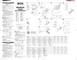
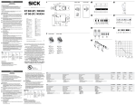
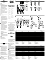
ENGLISH AWLL24-2X230 Fibre-optic Photoelectric Sensor with visible redlight Operating instructions Starting operation 1 O pen cover and guard of photoelectric proximity sensor; ensure that no dirt enters device. 2 With following connectors only: Equipment plug horizontally (H) and vertically (V) adjustable. Connect and secure cable receptacle tension-free. The following apply for connection in B: brn = brown, blu = blue. Only for versions with terminal chamber: Disconnect M16 screw fixing, remove sealing plugs. Cable outlet can be swivelled horizontally (H) and vertically (V). Feed tension-free supply cable through and connect photoelectric proximity sensor as per connection diagram B and tighten again the M16 screw fixing together with the sealing gasket to ensure the protection class “IP” of the device. Close protective cover. Mount sensor to suitable holders (e. g. SICK mounting bracket). Connect photoelectric sensor to operating voltage (see type label). 3 Principle of photoelectric proximity sensor: M aintain direction in which object moves relative to sensor. C heck application conditions such as sensing range, object size, and compare with characteristic in diagram. S etting of the sensing range: S et sensing range to max. position object. Position light spot on object. Red sender light spot visible on object. Signal strength indicator should light up. If it does not light up or if it is flashing, readjust and / or clean photoelectric proximity sensor and / or check application conditions. R emove the object, and then the LED signal strength indicator must switch off. If it does not switch off, turn the sensing range adjuster in the min. direction until the indicator switches off. 4 Princible for through-beam photoelectric sensor: Mount the fibre-optic cable opposite and align it roughly. Pay attention to the scanning range when you do this (see the technical data at the end of these operating instructions). Connect sensor to operating voltage (see type label). Alignment of light received. Set the sensitivity control to max. Adjust the fibre-optic cable until the LED signal strength indicator remains lit. Object detection check: Move object into the beam; the strength indicator should switch off. If it does not switch off or continues to blink, reduce the sensitivity using the “sensitivity control” switch until it switches off. It should switch on again after the object is removed. If it does not switch on again, adjust the sensitivity until the switching threshold is set correctly. DEUTSCH Lichtschranke mit Lichtleitern mit sichtbarem Rotlicht Betriebsanleitung Sicherheitshinweise >> Kennzeichnung: II 2G Ex ia op is IIC T4 Gb. >> Entspricht der Schutzart Eigensicherheit nach EN 60079-0 (2012), EN 60079-11 (2012), EN 60079-28 (2007) und EN 60947-5-6 (2000) (Schaltausgang NAMUR). Die Eigensicherheit ist nur in Zusammenschaltung mit einem entsprechend zugehörigen Betriebsmittel und gemäß dem Nachweis der Eigensicherheit gewährleistet. Die in der EG-Baumusterprüfbescheinigung enthaltenen Daten und Hinweise und die nationalen Errichterbestimmungen sind zu beachten. >> Vor der Inbetriebnahme die Betriebsanleitung lesen. >> Anschluss, Montage und Einstellung nur durch Fachpersonal. >> Gerät bei Inbetriebnahme vor Feuchte und Verunreinigung schützen. >> Kein Sicherheitsbauteil gemäß EU-Maschinenrichtlinie. Bestimmungsgemäße Verwendung Richtlinienkonformität Explosionsschutz: EG-Richtlinie 94 / 9 / EG. Die Geräte entsprechen der Kategorie 2 G und können in den explosionsgefährdeten Bereichen „Zone 1“ und „Zone 2“ eingesetzt werden. Die Lichtschranke WLL24-2Exi ist ein photoelektronischer Sensor und wird zum optischen, berührungslosen Erfassen von Sachen, Tieren und Personen eingesetzt. Inbetriebnahme 1 Deckel und Schutzhaube des Lichttasters öffnen; darauf achten, dass kein Schmutz in das Gerät gelangt. 2 Nur bei den Steckerversionen: Gerätestecker nach horizontal (H) und vertikal (V) schwenkbar. Leitungsdose spannungsfrei aufstecken und festschrauben. Für Anschluss in B gilt: brn = braun, blu = blau. 14 18 (3.44) 87.5 14 37.7 M5 (1.26) 27 (1.06) 1 +8.2 V 2 0V 1 2 3 4.7 (0.19) Österreich Phone +43 (0)22 36 62 28 8-0 Norge Phone +47 67 81 50 00 Polska Phone +48 22 837 40 50 România Phone +40 356 171 120 Russia Phone +7-495-775-05-30 Schweiz Phone +41 41 619 29 39 Singapore Phone +65 6744 3732 Slovenija Phone +386 (0)1-47 69 990 South Africa Phone +27 11 472 3733 South Korea Phone +82 2 786 6321/4 Suomi Phone +358-9-25 15 800 Sverige Phone +46 10 110 10 00 Taiwan Phone +886-2-2375-6288 Türkiye Phone +90 (216) 528 50 00 United Arab Emirates Phone +971 (0) 4 8865 878 USA/México Phone +1(952) 941-6780 (1.48) Australia Phone +61 3 9457 0600 Belgium/Luxembourg Phone +32 (0)2 466 55 66 Brasil Phone +55 11 3215-4900 Canada Phone +1 905 771 14 44 Česká republika Phone +420 2 57 91 18 50 China Phone +86 4000 121 000 +852-2153 6300 Danmark Phone +45 45 82 64 00 Deutschland Phone +49 211 5301-301 España Phone +34 93 480 31 00 France Phone +33 1 64 62 35 00 Great Britain Phone +44 (0)1727 831121 India Phone +91–22–4033 8333 Israel Phone +972-4-6801000 Italia Phone +39 02 27 43 41 Japan Phone +81 (0)3 5309 2112 Magyarország Phone +36 1 371 2680 Nederland Phone +31 (0)30 229 25 44 14 (0.55)(0.71) (0.55) WLL24-2Exi 30 (1.18) 4 1 2 3 4 +8.2 V brn 0V wht 0V blu 1 2 3 NC 4 1 2 3 4 +8.2 V brn 0V wht NC blu NC 11.8 (0.46) 65 (2.56) 74.7 (2.94) 1 3 2 4 SICK AG, Erwin-Sick-Strasse 1, D-79183 Waldkirch Please find detailed addresses and additional representatives and agencies in all major industrial nations at www.sick.com More representatives and agencies at www.sick.com ∙ Subject to change without notice ∙ The specified product features and technical data do not represent any guarantee. Weitere Niederlassungen finden Sie unter www.sick.com ∙ Irrtümer und Ä nderungen vorbehalten ∙ Angegebene Produkteigenschaften und technische Daten stellen keine Garantieerklärung dar. Plus de représentations et d’agences à l’adresse www.sick.com ∙ Sujet à modification sans préavis ∙ Les caractéristiques de produit et techniques indiquées ne constituent pas de déclaration de garantie. Para mais representantes e agências, consulte www.sick.com ∙ Alterações poderão ser feitas sem prévio aviso ∙ As características do produto e os dados técnicos apresentados não constituem declaração de garantia. Altri rappresentanti ed agenzie si trovano su www.sick.com ∙ Contenuti soggetti a modifiche senza preavviso ∙ Le caratteristiche del prodotto e i dati tecnici non rappresentano una dichiarazione di garanzia. Más representantes y agencias en www.sick.com ∙ Sujeto a cambio sin previo aviso ∙ Las características y los datos técnicos especificados no constituyen ninguna declaración de garantía. 欲了解更多代表机构和代理商信息,请登录 www.sick.com ∙ 如有更改 , 不另行通知 ∙ 对所给出的产品特性和技术参数 的正确性不予保证。 その他の営業所は www.sick.com よりご覧ください ∙ 予告なし に変更されることがあります ∙ 記載されている製品機能およ び技術データは保証を明示するものではありません。 Maintenance SICK photoelectric sensors are maintenance-free. We recommend doing the following regularly - clean the external lens surfaces. - check the screw connections and plug-in connections. No modifications may be made to devices. WLL2X430S01 7 10 (0.39) -------------------------------------------------------------- 8010641.Y508 0614 CV ------------------------------------------------------------ max. 32 Directive relevant conformity explosion prevention: EC-directive 94 / 9 / EC. The devices correspond to the category 2 G and can be used in potentially explosive atmosphere “zone 1” and “zone 2”. The WLL 24-2Exi fibre-optic photoelectric sensor is an photo electronic sensor and is used for optical, non-contact detection of objects, animals; and persons. WLL24-2X430 BZ int43 Correct use (0.28) (0.55) Safety notes >> Marking: II 2G Ex ia op is IIC T4 Gb. >> It corresponds to the intrinsic safety according to EN 60079-0 (2012), EN 60079-11 (2012), EN 60079-28 (2007) and EN 60947-5-6 (2000) (switching output: NAMUR). The intrinsic safety is only ensured in combination with the corresponding and appropriate consumable materials and in accordance with the Proof of Intrinsic Safety. The data and notes of the EC-Declaration of conformity and national installation directions should be observed. >> Read the operating instructions before starting operation. >> Connection, assembly, and settings only by competent technicians. >> Protect the device against moisture and soiling when operating. >> No safety component in accordance with EU machine guidelines. BWLL24-2X230 WLL24-2X430 WLL24-2X430S01 Nur bei Versionen mit Klemmenanschlussraum: M16-Verschraubung lösen, Dichtungsstopfen entfernen. Leitungsaustritt nach horizontal (H) und vertikal (V) schwenkbar. Spannungsfreie Versorgungsleitung durchführen und Lichtschranke nach Anschlussschema B anschließen und die M16-Verschraubung mit Dichtung wieder anziehen, damit die IP-Schutzart des Gerätes sichergestellt wird. Schutzklappe schließen. Sensor an geeigneten Halter anschrauben (z. B. SICK-Haltewinkel). Sensor an Betriebsspannung legen (s. Typenaufdruck). 3 Tasterprinzip: B ewegungsrichtung des Objektes relativ zum Sensor einhalten. E insatzbedingungen wie Schaltabstand, Objektgröße überprüfen und mit der Kennlinie im Diagramm vergleichen. E instellung Schaltabstand: S chaltabstand auf max. stellen. Objekt positionieren. Lichtfleck auf Objekt ausrichten. Sichtbarer roter Sendelichtfleck auf Objekt erkennbar. Empfangsanzeige muss permanent leuchten. Leuchtet sie nicht oder blinkt sie, Lichttaster neu justieren, reinigen bzw. Einsatzbedingungen überprüfen. O bjekt entfernen, die Empfangsanzeige muss erlöschen. Erlöscht sie nicht, Drehknopf in Richtung min. drehen, bis sie erlischt. Vorgang so lange wiederholen, bis die Schaltschwelle genau eingestellt ist. 4 Einwegprinzip: L ichtleiter gegenüberliegend montieren und grob ausrichten. Dabei Reichweite beachten (s. technische Daten am Ende dieser Betreibsanleitung). S ensor an Betriebsspannung legen (s. Typenaufdruck). J ustage Lichtempfang: D rehknopf auf max. stellen. L ichtleiter so lange justieren, bis Empfangsanzeige permanent leuchtet. K ontrolle Objekterfassung: Objekt in den Strahlengang bringen; die Empfangsanzeige muss erlöschen. Leuchtet sie weiterhin oder blinkt sie, die Empfindlichkeit am Drehknopf so lange reduzieren, bis sie erlischt. Nach Entfernen des Objektes muss sie wieder aufleuchten; ist dies nicht der Fall, Empfindlichkeit so lange verändern, bis die Schaltschwelle korrekt eingestellt ist. Wartung SICK-Lichtschranken sind wartungsfrei. Wir empfehlen, in r egelmäßigen Abständen – die optischen Grenzflächen zu reinigen, – Verschraubungen und Steckverbindungen zu überprüfen. Veränderungen an Geräten dürfen nicht vorgenommen werden. Ø 5 ... 10 mm (0.2 ... 0.39) WLL24-2Exi II 2G Ex ia op is IIC T4 Gb -X230 -X430 -X430S01 RW scanning range Sensing range max. Supply voltage VS Switching frequency max. Response time Switching output Enclosure rating Protection class Reichweite RW Schaltabstand max. Versorgungsspannung UV Schaltfolge max. Ansprechzeit Schaltausgang Schutzart Schutzklasse Portée RW Distance de commutation max. Tension d‘alimentation UV Le signal max. Temps de réponse Sortie de commutation Type de protection Classe de protection Alcance da luz RW Distância de comutação max. Tensão de força UV Sequência do sinal max. Tempo de reação Saída de comutação Tipo de proteção Classe de proteção 0 ... 100 mm / 0 ... 1000 mm 0 ... 40 mm 1) DC 8.2 V (Ri ca. 1 kOhm) (5.0 V … 15.5 V) 2) 3) 50 / s 4) ≥ 10 ms 5) EN 60947-5-6 (2000) (NAMUR) IP 65 Circuit protection Ambient operating temperature T4 EU-type examination certificate EU-Declaration of Conformity Voltage Ui Current Ii Power Pi Effective internal capacity Ci Effective internal inductivity Li Schutzschaltungen Betriebsumgebungstemperatur T4 EG-Baumusterprüfbescheinigung EG-Konformitätserklärung Spannung Ui Strom Ii Leistung Pi Wirksame innere Kapazität Ci Wirksame innere Induktivität Li Circuits de protection Température ambiante T4 Certificat d’essai d’homologation CE Déclaration de conformité CE Tension Ui Intensité Ii Puissance Pi Capacité interne efficace Ci Inductance interne efficace Li Circuitos protetores Temperatura ambiente de operação T4 Certificado de exame CE de tipo Declaração de conformidade da CE Tensão Ui Corrente Ii Potência Pi Capacidade interna eficaz Ci Indutância interna eficaz Li A, C 7) –20 °C < TA < +60 °C PTB 03 ATEX 2105 (www.sick.com) www.sick.com 15.5 V 53 mA 100 mW 80 nF ~0 µH 8) 1) 2) 3) 1) Objekt 90 % Remission nach DIN 5033 2) Versorgung mit Trennschaltgerät EN 2 Ex 3)Grenzwerte: 1) 2) 3) Objet Luminance de 90 % selon DIN 5033 Alimentation avec sectionneur EN 2 Ex Valeurs limites: Ondulation résiduelle max. 0,4 VSS 4) Pour un rapport clair / sombre 1:1 5) Durée du signal en charge ohmique 6) Tension de calcul 50 V c.c. 7) A = Raccordements U protégés contre V C = Suppression des impulsions parasites 8)Négligeable 1) 2) 3) 4) 5) 6) 7) 8) Object 90 % reflection according to DIN 5033 Provided with isolating switching device EN 2 Ex Limit values: Ripple max. 0.4 Vpp With light / dark ratio 1:1 Signal transit time with resistive load Reference voltage 50 V DC A = VS connections reversepolarity protected C = Interference pulse suppression Negligible small WLL24-2Exi II 2G Ex ia op is IIC T4 Gb Restwelligkeit max. 0,4 VSS Mit Hell- / Dunkelverhältnis 1:1 Signallaufzeit bei ohmscher Last Bemessungsspannung DC 50 V 7) A = U -Anschlüsse verpolsicher V C = Störimpulsunterdrückung 8) Vernachlässigbar klein 4) 5) 6) 4) 5) 6) 7) 8) Objeto: 90 % de remissão segundo DIN 5033 Alimentação com chave interruptora EN 2 Ex Valores limite: Ondulação residual max. 0,4 VSS Com uma relação luminoso / escuro de 1:1 Tempo de transição do sinal com carga ôhmica Tensão de dimensionamento DC 50 V A = Conexões UV protegidas contra inversão de polos C = Supressão de impulsos parasitas Negligentemente pequeno Portata RW Distanza di commutazione max. Tensione di alimentazione UV Sequenza signali max. Tempo di risposta Uscita di commutazione Tipo di protezione Classe di protezione Alcance RW Distancia de conmutación max. Tensión de alimentación UV Secuencia de señales max. Tiempo de reacción Salida de conexión Tipo de protección Protección clase 最大有效距离 RW 检测范围, 最大 検出距離範囲 RW、最大値 スイッチ間隔、最大値 电源电压UV 供給電圧 UV 最小信号序列 max. 触发时间 最小信号シーケンス max. 応答時間 开关输出端 スイッチング出力 Commutazioni di protezione Temperatura ambiente circostante T4 Attestato di certificazione CEE Dichiarazione di conformità CEE Tensione Ui Corrente Ii Potenza Pi Capacità interna efficace Ci Induttività interna efficace Li Circuitos de protección Temperatura ambiente de servicio T4 Certificado de homologación de tipo CE Declaración de conformidad de la CE Tensión Ui Corriente Ii Potencia Pi Capacidad interna efectiva Ci Inductividad interna efectiva Li 保护电路 保護回路 工作环境-温度 T4 使用周囲温度 T4 欧盟型式检验证书 欧盟一致性声明 电压 Ui 功率 Pi EU 型式検定合格証 EU 適合宣言書 電圧 Ui 電流 Ii 出力 Pi 内部有效电容 Ci 効果的な内部キャパシタンス Ci 内部有效电感 Li 効果的な内部インダクタンス Li 1) 2) 3) 1) 2) 3) 1) 2) 3) 90 % 漫反射比物体按照 DIN 5033 絶縁スイッチング装置 EN 2 Ex 装備 1) 2) 3) 亮 / 暗比 1:1 电阻性负载时,传感器检测到变化 时输出信号的转换时间 6) 限定电压DC 50 V 7) A = U -接头防反接 V C = 消除干扰脉冲 8) 几乎可以忽略 4) 5) 6) 4) 5) 6) 7) 8) Oggetto 90 %, remissione sec. DIN 5033 Alimentazione con separatore EN 2 Ex Valori limite: Ondulazione residua max. 0,4 VSS Con relatio chiaro / scuro 1:1 Tempo di continuare de segnale a resistenza ohmica Tensione di taratura DC 50 V A = UV-collegamenti con protez. contro inversione di poli C = Soppressione impulsi di disturbo Trascurabilmente piccola 4) 5) 6) 7) 8) Objeto 90 % de remission en base a DIN 5033 Alimentación con seccionador EN 2 Ex Valores límite: Ondulación residual max. 0,4 VSS Con una relación claro / oscuro de 1:1 Duración de la señal con carga óhmica Tensión tolerable DC 50 V A = Conexiones UV a prueba de inversión de polaridad C = Represión de impulso de interferencia Despreciablemente pequeña 保护种类 保護等級 保护级别 保護クラス 电流 Ii 4) 5) 操作电流: 极限值剩余波纹度 max. 0,4 VSS 対象物 90 % の反射率 DIN 5033 に準拠 配备有隔离开关装置 EN 2 Ex 限界値: 最大 0,4 VSS 明暗比率 1:1の場合 抵抗負荷における信号遷移時間 定格電圧 DC 50 V 7) A = U 接続 逆接保護 V C = 干渉パルス制御 8) 無視できるほど小さい 6) -X230 -X430 0 ... 100 mm / 0 ... 1000 mm 0 ... 40 mm 1) DC 8.2 V (Ri ca. 1 kOhm) (5.0 V … 15.5 V) 2) 3) 50 / s 4) ≥ 10 ms 5) EN 60947-5-6 (2000) (NAMUR) IP 65 6) A, C 7) –20 °C < TA < +60 °C PTB 03 ATEX 2105 (www.sick.com) www.sick.com 15.5 V 53 mA 100 mW 80 nF ~0 µH 8) FRANÇAIS Barrière à fibres optiques avec lumière de rouge Instructions de service Remarques relatives à la sécurité >> Marquage: II 2G Ex ia op is IIC T4 Gb >> Satisfait au type de protection Sécurité intrinsèque selon EN 60079-0 (2012), EN 60079-11 (2012), EN 60079-28 (2007) et EN 60947-5-6 (2000) (Sortie logique : NAMUR). La sécurité intrinsèque n’est assurée qu’en interconnexion avec un matériel électrique convenablement assorti et conformément au certificat de sécurité intrinsèque. Tenir compte des dispositions nationales d’installation et des données et recommandations contenues dans le certificat d’essai d’homologation CE. >> Lire les Instructions de Service avant la mise en marche. >> Installation, raccordement et réglage ne doivent être effectués que par du personnel qualifié. >> Lors de la mise en service, protéger l’appareil de l’humidité et des saletés. >> N’est pas un composant de sécurité au sens de la directive européenne concernant les machines. Utilisation conforme Conformité aux directives de protection antidéflagrante: Directive 94 / 9 / CEE. Les appareils sont de Catégorie 2 G et peuvent s’utiliser dans les atmosphères explosibles de « Zone 1 » et « Zone 2 ». La barrière réflex WLL24-2Exi est un capteur optoélectronique qui s’utilise pour la saisie optique de choses, d’animaux et de personnes sans aucun contact. Ouvrir le couvercle et le capot de protection du détecteur reflex ; 1 veiller à ce qu’aucune saleté ne pénètre dans l’appareil. 2 Seulement pour les versions à connecteur : Le connecteur peut pivoter horizontalement (H) et verticalement (V). Enficher la boîte à conducteurs sans aucune tension et la visser. Pour le raccordement dans B on a: brn = brun, blu = bleu. Seulement pour les versions à réceptacle de raccordement à bornes: Desserrer l’assemblage vissé M16, enlever le bouchon d’étanchéité. La sortie des conducteurs peut pivoter horizontalement (H) et verticalement (V). Faire passer la ligne d’alimentation exempte de tension et raccorder le détecteur reflex suivant le schéma de circuit B et serrer de nouveau l’embout vissé M16 avec son joint afin d’assurer le degré de protection IP de l’appareil. Fermer le volet de protection. Visser le capteur sur un support approprié (par ex. équerre de fixation SICK). Appliquer la tension de service au capteur (voir inscription indiquant le modèle). 3 Principe à détecteurs : Respecter le sens de déplacement de l’objet par rapport au capteur. Vérifier les conditions d’utilisation telles que distance de détection, taille de l’objet et les comparer à la courbe caractéristique du diagramme. R églage Distance de détection : R égler la distance de détection sur max. Positionner l’objet. Pointer la tache lumineuse vers l’objet. La tache rouge émise est visible sur l’objet. Le témoin de réception doit rester allumé en permanence. S’il n’est pas allumé ou s’il clignote, nettoyer ou ajuster à nouveau le détecteur, ou vérifier les conditions d’utilisation. E nlever l’objet, le témoin de réception doit s’éteindre. S’il ne s’éteint pas, tourner le bouton rotatif en direction max. jusqu’à ce qu’il séteigne. 4 Principe unidirectionnel : I nstaller le câble à fibres optiques en face, et l’aligner de façon grossière. Ce faisant, tenir compte de la portée (voir les caractéristiques techniques à la fin des présentes Instructions de Service). A justement Réception de la lumière : R égler le bouton rotatif en position max. A juster le câble à fibres optiques jusqu’à ce que le témoin de réception reste allumé en permanence. C ontrôle Saisie de l’objet : P lacer l’objet sur la trajectoire du rayon lumineux ; le témoin de réception doit s’éteindre. S’il reste allumé ou s’il clignote, réduire la sensibilité au bouton rotatif jusqu’à ce que le témoin s’éteigne. Lorsqu’on enlève l’objet, le témoin doit à nouveau s’allumer ; si ce n’est pas le cas, modifier la sensibilité jusqu’à ce que le seuil de détection soit correctement réglé. Maintenance Les barrières lumineuses SICK sont sans entretien. Nous vous recommandons de procéder régulièrement - au nettoyage des surfaces optiques - au contrôle des liaisons vissées et des connexions. Ne procédez à aucune modification sur les appareils. PORTUGUÊS Barreira de luz com luz vermelha visível (do campo espectral visível) Instruções de operação Notas de segurança >> Identificação: II 2G Ex ia op is IIC T4 Gb. >> Corresponde ao tipo de proteção segurança intrínseca segundo EN 60079-0 (2012), EN 60079-11 (2012), EN 60079-28 (2007) e EN 60947-5-6 (2000) (Saída de ligação: NAMUR). A segurança intrínseca só é garantida em conjugação com um meio de serviço correspondente e de acordo com o comprovante da segurança intrínseca. Devem ser observados os dados e as observações contidos no certificado de exame CE de tipo e as diretivas nacionais de instaladores. >> Antes do comissionamento dev ler as instruções de operação. >> Conexões, montagem e ajuste devem ser executados exclusivamente por pessoal devidamente qualificado. >> Guardar o aparelho ao abrigo de umidade e sujidade. >> Não se trata de elemento de segurança segundo a Diretiva Máquinas da União Europêa. Especificações de uso Conformidade com a diretiva de proteção contra a explosão: diretiva 94 / 9 / CE. Os aparelhos correspondem à categoria 2 G e podem ser utilizados nas áreas expostas ao perigo de explosão «zona 1» e «zona 2». A barreira de luz com reflexão por espelho WLL24-2Exi é um sensor optoeletrônico que serve para a análise ótica, sem contato, de objetos, animais e pessoas. Colocação em funcionamento 1 Abrir a tampa e a chapa protetora a foto-célula; atenção para não deixar entrar pó no interior do aparelho. 2 Vale somente para as versões com conetores: Os conetores dos aparelhos giram na horizontal (H) e na vertical (V). Enfiar a caixa de cabos sem torções e aparafusá-la. Para a ligação elétrica em B é: brn = marron, blu = azul. Só vale para os tipos com espaço para ligação de bornes: Afrouxar aconexão roscada M16, retirar a rolha de vedação. Saída da linha para giram na horizontal (H) e na vertical (V). Introduzir o cabo de força sem torção e conectar a foto-célula conforme indicado no esquema elétrico B e voltar a apertar a união roscada M16 com vedação para garantir o grau de proteção IP do aparelho. Fechar a chapa protetora. Aparafusar o sensor em suporte apropriado (p.ex. cantoneira de suporte SICK). Ligar o sensor à tensão de serviço (vide a indicação do tipo). 3 Princípio exploração: O bswervar sempre o sentido de movimento do objeto para com o sensor. Controlar os parâmetros de operação, como sejam raio de exploração, dimensões do objeto, e compará-los com a línha caraterística do diagrama. R egulação da amplitude do sensor: C olocar o raio de exploração no max. Posicionar o objeto. Centrar o ponto de luz no objeto. O ponto da luz deve ser visível sobre o objeto. O sinal de recepção deve acender em permanência. Caso não acenda ou acenda em intermitência, o sensor deve ser ajustado de novo, limpo, ou os parâmetros de operação devem ser controladas. R emover o objeto, e a vizualização apaga. Se nao for caso disso, rodar o botao, pelo menos, na direção max., aé que a vizualizaçao apague. 4 Princípio direção única: M ontar o condutor da luz em frente e proceder à retitificação por estimativa. A tender à amplitude de alcance (Ver datos técnicos destas instruções de uso). C olocar o sensor na tensao de serviço (ver letreiro de tipo). R egulação recepção luz: B otao giratório. Regular ao ponto max. A justar o condutor da luz, até que o monitor monitor acenda em luz permanente. C ontrole da exploraçao do objeto: C olocar o objeto à entrada de incidência dos raios de luz; apagar a indicaçao de recepçao mu. Se a luz continuar a acender ou fizer sinais intermitentes, reduzir a sensibilidade no botao rotativo até a luz apagar. Depois de remover objeto mu , a lâmpada voltará a acender; se nao for caso disso, alterar a sensibilidade, até que a fase de ligaçao esteja corretamente ligada. Manutenção As barreiras de luz SICK não requerem manutenção. Recomendamos que se efetue em intervalos regulares - uma limpeza das superfícies ópticas - uma verificação das conexões roscadas e dos conectores. Não são permitidas modificações no aparelho. ITALIANO Barriera luminosa con conduttori luminosi con luce rossa visibile Struzioni d’uso Avvertenze sulla sicurezza >> Contrassegno: II 2G Ex ia op is IIC T4 Gb. >> Corrisponde alla protezione a sicurezza intrinseca a norma EN 60079-0 (2012), EN 60079-11 (2012), EN 60079-28 (2007) e EN 60947-5-6 (2000) (Uscita di commutazione: NAMUR). La sicurezza intrinseca è garantita soltanto in connessione con un dispositivo idoneo e secondo quanto indicato nella certificazione della sicurezza intrinseca. Attenersi ai dati ed alle istruzioni contenuti nell’attestato di certificazione CEE ed alle disposizioni nazionali di installazione. >> Leggere prima della messa in esercizio. >> Allacciamento, montaggio e regolazione solo da parte di personale qualificato. >> Durante la messa in esercizio proteggere da umidità e sporcizia. >> Non componente di sicurezza secondo la Direttiva macchine EN. Impiego conforme agli usi previsti Conformità alle direttive sulla protezione antideflagrante: direttiva europea 94 / 9 / CE. Gli apparecchi rientrano nella categoria 2 G e possono essere impiegati nelle zone a rischio di esplosione «Zona 1» e «Zona 2». La barriera luminosa a riflessione WLL24-2Exi è un sensore optoelettronico che viene impiegatoper il rilevamento ottico a distanza di oggetti, animali e persone. Messa in funzione 1 Aprire il coperchio e la copertura di protezione del sensore luminoso; fare attenzione che non penetri sporcizia nell’apparecchio. 2 Solo con spine: Spina apparecchio orientabile in orizzontale (H) e in verticale (V). Inserire scatola esente da tensione e avvitare stringendo. Per collegamento B osservare: brn = marrone, blu = blu. Solo versioni con vano morsetti: Svitare, estrarre tappi ermetizzanti. Uscita cavo orientabile in horizzontale (H) e in verticale (V). Introdurre senza trazione il cavo di alimentazione e collegare il sensore luminoso secondo lo schema B e stringere di nuovo il collegamento a vite M16 con guarnizione, in modo da garantire il grado di protezione IP dell‘apparecchio. Chiudere la copertura di protezione. Avvitare il sensore su un supporto adatto (es. angoli di fissaggio SICK). Collegare il sensore alla tensione di esercizio (vedi targhetta di identificazione). 3 Principio di funzionamento a sensore: M antenere la direzione di moto dell’obbiettivo in relazione al sensore. V erificare le condizioni di impiego quali distanza di ricezione, dimensione dell’oggetto e confrontare con la curava caratteristica nel diagramma. I mpostazione distanza di ricezione: Impostare la distanza di ricezione su max. Posizionare l’oggetto. Il raggio di luce rossa deve essere visibile sull’oggetto. L’indicatore di ricezione deve essere acceso permanentemente. Se resta spento oppure lampeggia, riaggiustare il sensore oppure pulire oppure verificare nuovamente le condizioni di impiego. R imuovere l’oggetto, l’indicatore di ricezione deve spegnersi. Se non si spegne, ruotare la manopola verso max. finch‚ si spegne. 4 Principio di funzionamento a senso unico: Montare i fotoconduttori sui due lati ed allinearli approssimativamente tenendo conto della portata (v. caratteristiche tecniche alla fine di questo manuale). Allacciare il sensore a tensione di esercizio (v. stampigliatura). Aggiustaggio ricezione luce: Manopola in posizione max. Regolare il fotoconduttore / i fotoconduttori fino a quando l’indicatore di ricezione resta acceso permanentemente. Verifica rilevamento oggetto: Portare l’oggetto nel raggio di luce; l’indicatore di ricezione deve spegnersi. Se resta acceso o lampeggia, tarare la sensibilità con la manopola finché si spegne. Dopo la rimozione dell’oggetto deve riaccendersi. Se resta spento, tarare la sensibilità fino ad ottener e il limite di commutazione ottimale. Manutenzione Le barriere fotoelettriche SICK sono esenti da manutenzione. Consigliamo di pulire in intervalli regolari - le superfici limite ottiche - verificare i collegamenti a vite e gli innesti a spina. Non è consentito effettuare modifiche agli apparecchi. ESPAÑOL Barreras de luz con conductores de luz con luz roja visible Instrucciones de servicio Indicaciones de seguridad >> Marcado: II 2G Ex ia op is IIC T4 Gb. >> Esto equivale al grado de protección «Seguridad intrínseca» según EN 60079-0 (2012), EN 60079-11 (2012), EN 60079-28 (2007) y EN 60947-5-6 (2000) (Salida de conexión: NAMUR). La seguridad intrínseca sólo está garantizada en el caso de una conexión con un equipo correspondiente, y conforme a la comprobación de seguridad intrínseca. Han de observarse los datos y las indicaciones incluidos en el certificado de homologación de tipo CE, y las normas de instalación nacionales. >> Leer el Manual de Servicio antes de la puesta en marcha. >> Conexión, montaje y ajuste solo por personal técnico. >> A la puesta en marcha proteger el aparato contra humedad y suciedad. >> No es elemento constructivo de seguridad según la Directiva UE sobre maquinaria. Uso conforme a lo previsto Conformidad con la directiva relativa a la protección contra explosiones: Directiva CE 94 / 9 / CE. Los aparatos cumplen la categoría 2 G y pueden utilizarse en las áreas «Zona 1» y «Zona 2» con riesgo de explosiones. La barrera fotoelectrica de reflexión WLL24-2Exi es un sensor optoelectrónico, empleado para detección óptica y sin contacto de objetos, animales y personas. Puesta en funcionamiento 1 Abrir la tapa y la caperuza de protección del palpador fotoeléctrico de reflexión; procurar que no caiga suciedad en el aparato. 2 Solo en conectores: Conector del aparato orientable en horizontal (H) y vertical (V). Insertar y atornillar bien la caja de conexiones sin tensión. Para conectar en B: brn = marrón, blu = azul. Solo en las versiones con cámara de bornes: Aflojar el prensaestopas M16, Quitar los tapones de hermetización. Salida de la línea orientable en horizontal (H) y vertical (V). Pasar el cable de alimentación libre de tensión y conectar el palpador fotoeléctrico de reflexión siguiendo el esquema de conexiones B, y volver a apretar la unión roscada M16 con la junta para asegurar el grado de protección IP del aparato. Cerrar la trampilla de protección. Atornillar el sensor en un soporte adecuado (p. ej. escuadra de sujeción de SICK). Conectar el sensor a la tensión de servicio (ver la placa de características). 3 Principio de exploración: Mantener el sentido de movimiento del objeto paralelamente al sensor. Comprobar las condiciones de trabajo, como alcance de deteccion, tamaño del objeto y comparar con la línea característica en el diagrama. Ajuste del alcance de detección: Ajustar al max. el alcance de detección. Posicionar el objeto. Orientar la mancha fotoeléctrica hacia el objeto. Mancha fotoeléctrica roja emitida visible sobre el objeto. El piloto de recepción debe encenderse permanentemente. Si no se enciende o parpadea, ajustar entonces de nuevo el detector fotoeléctrico, limpiarlo y comprobar las condiciones de empleo. Alejar el objeto; debe apagarse el indicador de función. Si no se apaga, girar entonces el botón giratorio en dirección de max. hasta que se apague. 4 Principio unidireccional: Montar enfrente el conductor de luz y ajustarlo aproximadamente. Tener en cuenta el alcance (ver Características Técnicas al final del presente Manual de Servicio). Conectar el sensor a la tensión de servicio (ver impresión de tipo). Ajuste de recepción de luz: Ajustar el botón giratorio al max. Ajusar el conductor de luz hasta que el indicador de recepción se mantenga permanentemente encendido. Control de detección de objeto: Colocar el objeto en el paso del haz; debe apagarse el piloto de recepción. Si continúa encendido o parpadea, reducir entonces la sensibilidad por medio del botón giratorio hasta que se apague. Al quitar el objeto debe volverse a encender; si no fuera así, modificar entonces la sensibilidad hasta que el umbral de detección quede correctamente ajustad. Mantenimiento Las barreras fotoeléctricas SICK no precisan mantenimiento. En intervalos regulares, recomendamos - limpiar las superficies ópticas externas - comprobar las uniones roscadas y las conexiones. No se permite realizar modificaciones en los aparatos. 中文 日本語 使用光导体的光电开关 带可见红光 操作规程 光ファイバ付き光電センサ 可視赤色投光光源 取扱説明書 安全须知 安全上の注意事項 >> 标记: >> 認証番号: >> >> >> >> 防护等级。 仅当组合相应的附属工艺装备并符合本质安全证明时,才能保 证本质安全性。务请注意欧盟型式检验证书中包含的数据和提示以及相应 的国家安装规定。 调试前请阅读操作说明。 仅允许由专业人员进行接线、安装和设置。 调试时应防止设备受潮或脏污。 本设备非欧盟机器指令中定义的安全元件。 >> >> >> 造は、付属する適切な関連装置と共に、本質安全証明に従って使用する 場合にのみ保証されます。 EU 型式検定合格証内に含まれるデータ およ び 注意事項、そして各国の製造者責任法令を遵守してください。 使用を開始する前に取扱説明書をお読みください。 接続、取付けおよび設定できるのは専門技術者に限ります。 装置を使用開始する際には、濡れたり汚れたりしないように保護して ください。 本製品は EU 機械指令の要件を満たす安全コンポーネントではありま せん。 II 2G Ex ia op is IIC T4 Gb. >> 符合依据 EN 60079-0 (2012)、 EN 60079-11 (2012)、EN 60079-28 (2007) 和 EN 60947-5-6 (2000)(开关输出端 NAMUR)的本质安全型 正确使用须知 防爆指令合规性:EC 指令 94 / 9 / EC。 设备符合 2G 类别并可用于“1 区”和“2 区”的易爆环境。 反射光栅 WLL24-2Exi 是一种光电传感器,用于对物体、动物和人体进行无接 触的光学检测。 调试 1 打开光电传感器的盖子和保护套;注意污渍不得进入设备内部。 2 仅针对带插头的型号: 设备插头可以沿水平 (H) 和垂直 (V) 方向转动。在不通电的情况下插上电 缆插座并拧紧。 >> 使用目的 防爆指令適合:EC 指令 94 / 9 / EG。 同デバイスは、カテゴリ 2 G に対応しており、爆発の危険のある領域「ゾー ン 1」および「ゾーン 2」で使用することができます。 リフレクタ形光電スイッチ WLL24-2Exi とは光電センサであり、物体、動物 または人物などを光学技術により非接触で検知するための装置です。 使用開始 1 针 对 B 的接口:brn = 棕色,blu = 蓝色。 开 M16 螺栓连接,取下密封塞。 导线出口可以沿水平 (H) 和垂直 (V) 松 方向转动。 穿过无电压的供电导线且根据连接图 B 连接光栅, 重新拧紧 配有密封件的 M16 螺栓连接,从而确保达到设备的 IP 防护等级。 配件产品系列。 将传感器接上工作电压 (参考标签上的型号)。 3 扫描原理: 物件的运动方向应与光探器适当相应。 检查使用条件,如开关距离、物体大小,并与图中的特征线进行比较。 扫描范围设置 将开关距离设置为最大。 将检测物定位。将光斑对准物体,物体上可以看到红 色光点。 受光灯应显亮。不亮或闪亮时,重新校准光 探器,清洁及检查使用条件。 最小值方向转动旋钮,在其熄灭前切勿中断这一动作。 沿 不断重复这一过程,直至精确设置开关阈值。 4 透射原理: 反向安装光导体并粗略校准。安装时应注意有效距离 (参见本操作说明书 末页的技术数据)。 将传感器接上工作电压 (参考标签上的型号)。 校准受光: 将旋钮调至最大。 调节光导体长度,直至受光指示灯长亮。 物 体识别检查: 将物体置于光路中,接收指示灯须熄灭。 如果指示灯仍然亮起或闪烁, 则通过旋钮减小灵敏度,直至其熄灭。 移开物体后,指示灯必须重新亮 起;否则须更改灵敏度,直至开关阈正确设置。 保养 SICK 光电开关无需保养。 我们建议,定期 - 清洁镜头检测面 - 检查螺丝接头和插头连接。 不得对设备进行任何改装。 電スイッチのふたと保護カバーを開く: デバイス内部に 汚れが入り 光 込まないよう注意します。 2 以下のプラグタイプの場合のみ: デバイスプラグは水平「H」および垂直「V」に動かすことができま 仅针对带端子连接盒的型号: 关闭防护罩。 将传感器安装在一个合适的支架上。合适的固定角板 请参见 SICK II 2G Ex ia op is IIC T4 Gb. >> EN 60079-0「2012年」、 EN 60079-11「2012 年」、EN 6007928「2007 年」 および EN 60947-5-6「2000 年」 に準拠した本質安 全防爆保護に適合「スイッチング出力 NAMUR」。 この本質安全防爆構 す。ケーブルプラグをケーブルに張力がかからないように差し込み、 ネジ止めします。 B の接続:brn = 茶、blu = 青。 端子接続ネジ仕様の場合のみ: M16 ネジ止めを外し、シールキャップを取り除きます。 ケーブル出口 は水平「H」および垂直「V」に動かすことができます。 電圧のかか っていない電源供給ケーブルを通し、 光電スイッチを 取付け図 B に従 って接続し、 デバイスの IP 保護等級を確保するために、シールを再び M16 ネジで締め付けます。 保護キャップを閉じます。 適 切なホルダーにセンサを取り付けてください。適切な ギュメ は、SICK の付属品プログラムで見つけることが できます。 センサに稼働電圧を供給します「型式ラベル参照」。 3 ボタン原理: 対象物の移動方向がセンサに対し、相対的になるように維持します。 スイッチング距離、対象物の大きさなどの使用条件を点検し、図の指 数と比較します。 検出距離の設定 スイッチング距離を最大に設定します。 対象物を位置付けします。光点を対象物に位置づ けます。対象物上に 赤色の投光スポットが見えます。 信号強度表示は継続して点灯してい なければなりま せん。信号強度表示が点灯しないまたは点滅する場合 は、光電スイッチを改めて調節し、汚れを取り除くか、 あるいは使用 条件を確認してください。 表示灯が消えない場合は、消えるまでロータリースイッチをマイナス 方向へ回します。スイッチング閾値が正確に設定されるまで手順を繰 り返します。 4 透過原理: 光ファイバを向かい側に取り付け、おおまかに方向を合わせます。そ の際検出距離範囲に注意します「本取扱説明書の終わりにある技術仕 様を参照」。 センサに稼働電圧を供給します「型式ラベル参照」。 受光調整: ロータリースイッチを最大に設定します。 受光表示灯が恒久的に点灯するまで光ファイバを調整します。 対 象物検出の点検: 対象物を光軸に移動させます。信号強度表示が消えるはずです。 点灯 し続ける、または点滅する場合、消灯するまでロータリースイッチの 感度を下げていきます。 対象物を除去した後、表示が再び点灯しなけ ればなりません。そうでない場合には、 スイッチング閾値が正しく調 整されるまで、 感度を変更します。 メンテナンス SICK の光電スイッチはメンテナンス不要です。 推奨する定期的な保全作業 - レンズ境界面の清掃 - ネジ締結と差込み締結の点検 デバイスに変更を加えることは一切禁止されています。