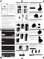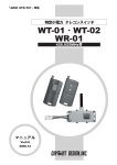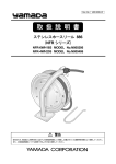
1
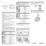
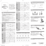
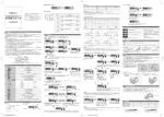
ソレノイドバルブ着脱方法
電気回路図
●注意
1 .コネクタケーブルに過大な引張力、極端な曲げ、ケーブルの繰り返し動作等は避けてください。製品の破損、ケーブル断線の原因となる可能性があります。
この度は、ピスコ製品をお買い上げいた
だき誠にありがとうございます。
本製品をお客様に安心してお使いいただ
くために、本取扱説明書を必ずお読みく
ださい。又、本書は大切に保管していた
だきますようお願い申し上げます。
製品カタログには、ピスコ製品、及びピ
スコ電磁弁共通の取扱い上の注意事項が
記載されています。本製品のご使用にあ
たっては、製品カタログの注意事項につ
いても併せてご確認ください。
ソレノイドバルブ
SVR10 シリーズ
取扱説明書
●Dサブコネクタ
9ピン
9ピン
st 1 14(A)側コイル
12(B)側コイル
st 2 14(A)側コイル
12(B)側コイル
8
st 4 14(A)側コイル
12(B)側コイル
14(A)側コイル
12(B)側コイル
14(A)側コイル
12(B)側コイル
14(A)側コイル
12(B)側コイル
14(A)側コイル
12(B)側コイル
14(A)側コイル
12(B)側コイル
14(A)側コイル
12(B)側コイル
14(A)側コイル
12(B)側コイル
14(A)側コイル
12(B)側コイル
14(A)側コイル
12(B)側コイル
14(A)側コイル
12(B)側コイル
14(A)側コイル
12(B)側コイル
14(A)側コイル
12(B)側コイル
st 2
st 3
st 4
st 5
st 6
st 7
st 8
st 9
st 10
st 11
注)AC100V 仕様電磁弁は、CE マーキング対象外となりま
す。
注)マニホールド部へは、CE マーキングの表示はしており
ません。
st 12
+
-
-
5
14
15
16
17
18
19
20
21
22
23
24
25
COMMON
+V
1
st 1
2
st 2
3
st 3
4
st 4
5
st 5
6
st 6
7
st 7
8
st 8
9
st 9
10
st 10
11
st 11
12
st 12
14(A)側コイル
12(B)側コイル
14(A)側コイル
12(B)側コイル
14(A)側コイル
12(B)側コイル
14(A)側コイル
12(B)側コイル
14(A)側コイル
12(B)側コイル
14(A)側コイル
12(B)側コイル
14(A)側コイル
12(B)側コイル
14(A)側コイル
12(B)側コイル
14(A)側コイル
12(B)側コイル
14(A)側コイル
12(B)側コイル
14(A)側コイル
12(B)側コイル
14(A)側コイル
12(B)側コイル
14
15
16
17
18
19
20
21
22
23
24
25
COMMON
13
DC24V
2
3
+
-
4
5
6
コネクタ
7
8
9
+
10
(図1)
-
11
12
個別差込コネクタの着脱
13
●注意
1 . 個別差込コネクタ(ケーブル)には、強い引張力や極端な曲げを与えないでください。断線、またはコネクタ部の破損の原因となる可能性が
あります。
●個別差込コネクタ
シングルソレノイド
注意事項
+
ダブルソレノイド
-
+
■個別差込コネクタの装着は、止まるまで差し込
むだけでセットできます。(図 2)
■コネクタを外す場合は、コネクタのレバーを矢
印方向に押しながら引抜いてください。(図 3)
レバー
コネクタ裏
-
(黒)14(A)側コイル
●警告
1 . 圧縮空気は、取り扱いを誤ると危険です。空気圧機器を使用した機械・装置の組立てやメンテナンスなどは、十分な知識と経験を持った人が行っ
てください。
2 . 製品の保守点検等を行う場合には、供給している電源を切り、供給エアーを止め配管内の残圧を確実に排気させてから行ってください。マニホー
ルドからのユニットの着脱を行う場合にも供給エアーの停止と配管内の残圧排気は必ず行ってください。
3 . 本製品は、防爆構造ではありません。引火性、爆発性のあるガス、流体、雰囲気中での使用は避けてください。
4 . パイロットバルブへ長時間連続通電するとコイルより発熱します。熱による火傷、及び周辺機器への影響を与える可能性があります。長時間連
続通電される場合はご相談ください。
5 . 水滴、油滴、塵埃のかかる所では使用しないでください。防滴構造ではありませんので作動不良の原因となる可能性があります。
白:12(B)側コイル
(赤)COMMON
1 . 使用圧力範囲外での使用はしないでください。使用圧力範囲を超える圧力で使用した場合には、破損、変形の危険性があります。
2 . バルブは漏れを許容していますので、漏れ量がゼロを必要とする使い方では使用しないでください。
3 . バルブは大容量のエアーブロー用として使用しないでください。内部パイロット型構造になっていますので内部圧力の低下により作動不良の原
因となる可能性があります。
4 . 手動操作によりバルブの切換を行うと接続されたアクチュエータなどが作動します。安全を確認の上操作を行ってください。
5 . 配線は必ず電源を切ってから行ってください。また、配線時には線の色を確認してください。
6 . バルブは無給油で使用できますが給油される場合は、タービン油 1 種 (ISO VG32) をご使用ください。途中で給油を止めると初期潤滑剤の消失
により作動不良を起こすことがありますので給油は続けて行ってください。
7 . バルブの各ポートを本体の刻印表示により確認し、配管を行ってください。
8 . 保守、点検は電源を切り、エアーを止め、配管内の圧力がゼロになったことを確認してから行ってください。尚、3 位置クローズドセンタタイプは、
バルブとアクチュエータ間にエアーが残っていますのでご注意ください。
9 . マニホールドのサイレンサ仕様は、エレメントの目詰まりにより排気抵抗が上がります。システム全体の機能低下の原因となる可能性がありま
すので定期的に保守、点検を行ってください。
10. 止めピンを抜くことによりカートリッジ継手の着脱が可能ですが、使用時には止めピンが確実に挿入されていることを確認してください。
11. 外部パイロットエアー仕様を選択した場合で、ツイン3方弁(バルブタイプE・F・G・H) を搭載する場合は、供給ポート1(P)の圧力を0.2MPa 以上
とし、尚且つ[パイロットエアー圧力≧供給ポート1(P)圧力]としてください。圧力が低いと動作不良の原因となります。
(∼)青
(∼)青
黒:14(A)側コイル
赤:COM +V
(白)12(B)側コイル
(注)( )内はリード線色。
+
(∼)12(B)側コイル
(白)
(∼)14(A)側コイル
(黒)
●フラットケーブルコネクタ(DC24V)
10ピン
st 1
st 2
st 3
st 4
st 7
SVR10□□-□-D
Dサブコネクタ仕様
ピン数
サイレンサ
st 1
4
st 2
5
6
st 3
7
8
st 4
9
10
st 5
st 6
st 9
st 10
三角マーク表示位置
st 8
st 9
14(A)側コイル
12(B)側コイル
14(A)側コイル
12(B)側コイル
14(A)側コイル
12(B)側コイル
14(A)側コイル
12(B)側コイル
14(A)側コイル
12(B)側コイル
14(A)側コイル
12(B)側コイル
14(A)側コイル
12(B)側コイル
14(A)側コイル
12(B)側コイル
14(A)側コイル
12(B)側コイル
1
st 11
2
項 目
作動方式
弁構造
ポジション数
ポート数
弁機能
パイロット占有点数
SVR10D
→ ON
→ OFF
最高作動頻度
最小励磁時間
耐振動
耐衝撃
給 油
使用圧力範囲
−
4
5
6
7
8
9
10
11
12
13
14
15
16
17
18
19
20
21
22
23
24
25
26
st 1
st 2
st 3
st 4
st 5
st 6
st 7
st 8
st 9
st 10
st 11
st 12
st 13
5
6
7
8
st 16
st 14
(注) COMMON(+V)ピン No.25・26は内部で短絡。
st 15
9
10
st 17
11
12
st 18
13
14
15
16
17
18
19
20
st 19
14(A)側コイル
12(B)側コイル
14(A)側コイル
12(B)側コイル
14(A)側コイル
12(B)側コイル
14(A)側コイル
12(B)側コイル
14(A)側コイル
12(B)側コイル
14(A)側コイル
12(B)側コイル
14(A)側コイル
12(B)側コイル
14(A)側コイル
12(B)側コイル
14(A)側コイル
12(B)側コイル
14(A)側コイル
12(B)側コイル
14(A)側コイル
12(B)側コイル
14(A)側コイル
12(B)側コイル
14(A)側コイル
12(B)側コイル
14(A)側コイル
12(B)側コイル
14(A)側コイル
12(B)側コイル
14(A)側コイル
12(B)側コイル
14(A)側コイル
12(B)側コイル
14(A)側コイル
12(B)側コイル
14(A)側コイル
12(B)側コイル
1
2
3
4
5
8
9
10
11
12
13
14
15
16
17
18
19
20
21
22
23
24
25
26
27
28
29
30
31
32
33
34
35
36
37
38
39
40
(図6)
締付けスリーブ
チューブ
+
st 1
st 2
st 3
st 4
14(A)側コイル
12(B)側コイル
14(A)側コイル
12(B)側コイル
14(A)側コイル
12(B)側コイル
14(A)側コイル
12(B)側コイル
●注意
2
st 1
3
4
st 2
5
6
st 3
8
9
10
+
-
st 4
st 5
COMMON
st 6
st 7
st 9
st 10
st 11
SVR10E
SVR10F
SVR10G
SVR10H
20ピン
三角マーク表示位置
st 12
三角マーク表示位置
14(A)側コイル
12(B)側コイル
14(A)側コイル
12(B)側コイル
14(A)側コイル
12(B)側コイル
14(A)側コイル
12(B)側コイル
14(A)側コイル
12(B)側コイル
14(A)側コイル
12(B)側コイル
14(A)側コイル
12(B)側コイル
14(A)側コイル
12(B)側コイル
14(A)側コイル
12(B)側コイル
14(A)側コイル
12(B)側コイル
14(A)側コイル
12(B)側コイル
14(A)側コイル
12(B)側コイル
1
2
3
4
5
6
7
8
9
10
11
12
13
14
15
16
17
18
19
20
21
22
23
24
25
26
st 1
+
-
st 2
st 3
st 4
st 5
st 6
st 7
st 8
st 9
14(A)側コイル
12(B)側コイル
14(A)側コイル
12(B)側コイル
14(A)側コイル
12(B)側コイル
14(A)側コイル
12(B)側コイル
14(A)側コイル
12(B)側コイル
14(A)側コイル
12(B)側コイル
14(A)側コイル
12(B)側コイル
14(A)側コイル
12(B)側コイル
14(A)側コイル
12(B)側コイル
st 2
st 3
st 4
st 5
+
-
st 6
st 7
st 8
st 9
st 10
st 11
st 12
st 13
COMMON
st 1
st 14
st 15
1
2
3
4
5
6
7
8
st 18
9
10
st 19
11
12
13
14
15
16
17
18
19
20
(注) COMMONピン No.25・26は内部で短絡。
+
+
三角マーク表示位置
-
-
st 16
st 17
14(A)側コイル
12(B)側コイル
14(A)側コイル
12(B)側コイル
14(A)側コイル
12(B)側コイル
14(A)側コイル
12(B)側コイル
14(A)側コイル
12(B)側コイル
14(A)側コイル
12(B)側コイル
14(A)側コイル
12(B)側コイル
14(A)側コイル
12(B)側コイル
14(A)側コイル
12(B)側コイル
14(A)側コイル
12(B)側コイル
14(A)側コイル
12(B)側コイル
14(A)側コイル
12(B)側コイル
14(A)側コイル
12(B)側コイル
14(A)側コイル
12(B)側コイル
14(A)側コイル
12(B)側コイル
14(A)側コイル
12(B)側コイル
14(A)側コイル
12(B)側コイル
14(A)側コイル
12(B)側コイル
14(A)側コイル
12(B)側コイル
1
2
3
4
5
6
7
8
9
10
11
12
13
14
15
16
17
18
19
20
21
22
23
24
25
26
27
28
29
30
31
32
33
34
35
36
37
38
39
40
+
+
-
COMMON
(注) COMMONピン No.39・40は内部で短絡。
チューブ着脱方法
① . チューブの装着
ソレノイドバルブ SVR は、チューブ
をチューブエンドまで差し込むだけ
でロック爪が固定、弾性体スリーブが
チューブの外周をシールします。装着
の際は、弊社総合カタログ、継手の共
通注意事項「2. チューブ装着上の注意」
を参考に装着してください。
直接動作
弾性体シール、ポペット弁
AC90 ~ 110V
1VA
ブリッジダイオード
プッシュロック式
0.7MPa
LED (4(A):緑色、2(B):赤色)
② . チューブの取外し
チューブを取外す場合、開放リングを
押すことによりロック爪が開き、チュー
ブを抜くことができます。
取外しの際は、必ずエアーを止めてか
ら行ってください。
●注意
① . RF35S に搭載する製品をネジ (※1) で固定します。
※1. ネジは、M3 × 0.5 (l =8 ~ 10)をご使用ください。
② . DRF35Sを DINレールにはめ込み、DRF35S取付けネジを規定のトルク(下表を参照)で締付けます。
■表. 取付ネジの締付けトルク
0.3 ~ 0.4N·m
100N
取付ネジ締付けトルク
最大積載荷重
マニホールド取付けネジ
5(R1)
4(A)
2(B)
12
4(A)
1(P)
3(R2)
5(R1)
4(A)
2(B)
3(R2)
5(R1)
4(A)
1(P)
1(P)
2(B)
3(R2)
5(R1)
5(R1)
1(P)
3(R2)
3(R2)
4(A)
2(B)
12
12
5(R1)
1(P)
3(R2)
DRF35S取付けネジ
14
4(A)
2(B)
5(R1)
1(P)
3(R2)
12
12
(2)
(3)
※ . その他詳細につきましては、下記までお問い合わせください。
4(A)
2(B)
販売元/
12
②
②
(1)
2(B)
12
12
①
1 . ソレノイドバルブを 49m/s2 以下の振動の中で使用する場合、振動方向がスプール弁に対し直角になるように取付けてください。(49m/s2 以
下の振動でご使用ください。)
4(A)
1(P)
2(B)
14
①
DINレール
14
14
14
14
▲
▲
▲
▲
14
14
12
▲
▲
▲
▲
▲
E
パッキン
1 . 取付ネジは、必ず規定のトルクで締付けてください。
2. 最大積載荷重を超える質量の物を搭載しないでください。
3. 極端に振動の激しい所への取付けは、避けてください。(9.8m/s2 以下)
●警告
記号
エレメントカバー
エレメント
③ . DRF35S取付けネジを緩め、供試品を持ち上げるようにして手前に倒し、DINレールから外します。
記号 F
記号 G
記号 H
記号 A
記号 R
記号 P
3 ポート 2 ポジション
5 ポート 3 ポジション
4(A).ノーマルクローズ 4(A).ノーマルオープン
4(A). 2(B).ノーマルクローズ 4(A). 2(B).ノーマルオープン
2(B).ノーマルオープン 2(B).ノーマルクローズ クローズドセンタ エキゾーストセンタ プレッシャセンタ
シングルソレノイド ダブルソレノイド
(ツイン 3 方弁)
(ツイン 3 方弁)
(ツイン 3 方弁)
(ツイン 3 方弁)
4(A)
2(B)
エレメントカバー取付け用ネジ
■サイレンサ付排気ポート (大気開放型) のエレメント交換は、次の手順により行ってくださ
い。
① . エレメントカバー取付用ネジ (6本) を外します。
② . エレメント (型式:SVR10EX-E) を取り外します。
③ . 新しいエレメントを取付け、エレメントカバーをセットし取付用ネジで固定してくだ
さい。
(樹脂用タッピングネジを使用しているため、精密ドライバなどで噛み合いを確認後、
本締めを行ってください。推奨締付けトルク:0.25 ~ 0.3N·m)
※パッキンが溝に確実に装着されていることを確認してから取付けてください。
製品固定方法
記号 S
記号 D
5 ポート 2 ポジション
5(R1)
1(P)
3(R2)
●注意
1 . エレメントカバーは 0.25 ~ 0.3N・m の締付トルクにて確実に締付けてください。
DIN レール取付金具着脱方法
●警告
バルブタイプ
14
サイレンサエレメントの交換手順
(図10)
AC100V
DC24.6 ~ 26.4V
0.7W
サージアブソーバ
(図9)
(注) COMMONピン No.19・20は内部で短絡。
1 . 取り外しの際は、必ずエアーを止め、残圧を排気してから行ってください。
2 . 配管作業を行う場合には、供給・出力・排気の各ポートを間違えないように、必ず製品カタログ等により、各ポート位置を確認してください。
DC24V
2(B)ポート
-
■パイロットバルブ
定格電圧
4(A)ポート
COMMON
*1. 空気圧:0.5MPa 供給時の値です。
*2. 3ポジションは、中立位置から作動状態が “ → ON”、作動状態から中立位置が “ → OFF” の値です。
項 目
作動方式
弁構造
許容電圧範囲
消費電力 (ランプ付)
サージ保護回路
手動操作
最高使用圧力
ランプ
時計ドライバ
1 . 手動操作によりバルブの切換を行うと接続されたアクチュエータなどが作動
します。安全を確認の上操作を行ってください。
2.マニュアルボタンに必要以上の力を加えないでください。破損の原因になります。
■手動操作によりバルブの切換が行えます。(パイロット圧の供給時のみ作動します。
)
■時計ドライバでマニュアルボタンを止まる位置まで押し、時計方向へ回すとロッ
クします。ロックの解除はマニュアルボタンを半時計 方向へ回すと解除されま
す。(4(A)側:緑色、2(B)側:赤色、また時計ドライバを回す時のトルクは、0.05N·m
以下に抑えてしてください。)
■マニュアルボタンは平常運転開始前に必ずロックを解除してください。
-
1
7
40ピン
(図7)
手動操作
(注) COMMON(+V)ピン No.39・40は内部で短絡。
26ピン
チューブエンド
チューブ
締付継手
(図5)
COMMON
+V
三角マーク表示位置
φ 8mm ウレタンチューブ専用締付継手の配管方法
■配管接続口 (4(A)ポート・2(B)ポート) 用締付継手は、下記の手順により配管してください。(図4)
① . 締付継手をマニホールド本体より分離してください。
② . 締付継手に締付けスリーブが突き当たるまで廻してください。(図6)
③ . チューブを奥 (チューブエンド) まで差し込んでください。(図7)(締付継手には必ずウレタンチューブをご使用ください。)
④ . 反時計廻りにスリーブを手、またはラジオペンチで 6 ~ 8 回転廻してください。
⑤ . 締付継手をマニホールドに装着してください。
※マニホールドに取付けた後は、必ず止めピンをセットしてください。
6
7
●フラットケーブルコネクタ(AC100V)
10ピン
コネクタ
三角マーク表示位置
(注) COMMON(+V)ピン No.19・20は内部で短絡。
パイロットバルブによる空気作動
弾性体シール、スプール弁
2ポジション
3ポジション
2ポジション
5ポート
3ポート×2
ダブル
シングル×2
2
8msec
8msec (*2)
10msec
−
13msec (*3)
13msec
5Hz
50msec
−
−
49m/s2
150m/s2
不要
0.2 ~ 0.7MPa (外部パイロットエアー仕様の場合:0 ~ 0.7MPa)
シングル
1
11msec
6msec
2
3
4
(注) COMMONピン No.9・10は内部で短絡。
SVR10S
1
COMMON
+V
■メインバルブ
SVR10A
SVR10R
SVR10P
14(A)側コイル
12(B)側コイル
14(A)側コイル
12(B)側コイル
14(A)側コイル
12(B)側コイル
14(A)側コイル
12(B)側コイル
14(A)側コイル
12(B)側コイル
14(A)側コイル
12(B)側コイル
14(A)側コイル
12(B)側コイル
14(A)側コイル
12(B)側コイル
14(A)側コイル
12(B)側コイル
14(A)側コイル
12(B)側コイル
14(A)側コイル
12(B)側コイル
14(A)側コイル
12(B)側コイル
3
st 8
形 式
40ピン
三角マーク表示位置
COMMON
+V
*1. ツイン 3 方弁搭載の場合、0.2 ~ 0.7MPa
応答時間 (*1)
st 7
st 12
st 1
st 6
配線方式
2
3
st 8
st 5
タイプ
1
20ピン
■マニホールド
耐 圧
使用温度範囲
取付方向
耐振動
耐衝撃
メインバルブ搭載可能数
14(A)側コイル
12(B)側コイル
14(A)側コイル
12(B)側コイル
14(A)側コイル
12(B)側コイル
14(A)側コイル
12(B)側コイル
(注) COMMON(+V)ピン No.9・10は内部で短絡。
st 4
使用圧力範囲
26ピン
三角マーク表示位置
COMMON
+V
st 3
項 目
使用流体
AC100V
DC24V
仕 様
SVR10□□-□-F
SVR10□□-□-S
個別差込コネクタ仕様
フラットケーブルコネクタ仕様
空気
0.2 ~ 0.7MPa (外部パイロットエアー仕様の場合:0 ~ 0.7MPa*1)
外部パイロットエアー供給ポート圧力範囲:0.2 ~ 0.7MPa
1.05MPa
5 ~ 50°C
自由
49m/s2
150m/s2
Max 12 台
Max 20 台
D サブコネクタ
フラットケーブルコネクタ
個別差込コネクタ
2 ~ 4 連:9 ピン
2 ~ 4 連:10 ピン
3 ピン
5 ~ 12 連:25 ピン
5 ~ 9 連:20 ピン
10 ~ 12 連:26 ピン
5(R1), 3(R2)ポート大気開放のみ標準装備
(図2)
-
(∼)Common
(青)
st 2
形 式
(図3)
+V
●注意
5(R1)
1(P)
3(R2)
パッキン
SVR10シリーズ
0.18 ~ 0.22N·m
バルブシリーズ
推奨締付けトルク
1
AC100V
HIR0036-00
固定用ネジ
■マニホールド固定ネジ締付け推奨トルク
バルブをマニホールドに取付ける際、下記推奨締付けトルクに従い締付けを行ってくだ
さい。推奨以外での締付けは、緩み・破損の原因になります。
25ピン
25ピン
st 1
+
プラスドライバ
4
9
COMMON
5
3
8
st 4 14(A)側コイル
12(B)側コイル
4
9
COMMON
+V
2
7
st 3 14(A)側コイル
12(B)側コイル
3
1
6
st 2 14(A)側コイル
12(B)側コイル
2
7
st 3 14(A)側コイル
12(B)側コイル
st 1 14(A)側コイル
12(B)側コイル
1
6
■ソレノイドバルブをマニホールドより着脱する場合は下記の手順により行ってくださ
い。
① . プラスドライバでソレノイドバルブ固定用ネジ(2 本)を廻し、完全にバルブよりネ
ジを外します。
② . ソレノイドバルブを(図 1)の矢印の方向へ真っ直ぐ引き抜いてください。
③ . ソレノイドバルブをマニホールドは取付ける場合は、コネクタとの接続に注意し、
マニホールドに対して真っ直ぐ装着してください。
※パッキンが溝に確実に装着されていることを確認してから取付けてください。
④ . 固定用ネジを締付けてください。
製造元/
本社・営業部/長野県上伊那郡南箕輪村 3884-1 〒 399-4586
本社工場/長野県岡谷市長地出早 3-9-32 〒 394-0089
TEL : 0265(76)2511 豎 FAX : 0265(76)2851
TEL : 0266(28)6072 豎 FAX : 0266(28)7349
How to mount / remove the solenoid valves onto / from the manifold
Electric circuit diagram
● Caution
Thank you for purchasing PISCO
product. Please be sure to read this
User's Manual before using this item in
order to make sure the safety. Please
keep this manual handy with care, so that
you can refer to it whenever necessary.
PISCO products catalogues include
Common Safety Instructions for PISCO
products and Solenoid Valves. Please
confirm the Safety Instructions as well
before using this item.
Solenoid Valve
SVR10 Series
User's Manual
1 . Do not pull or bend the connector cable with excessive force and also avoid repeat action on the cable. Doing so may result in the products
broken and the cables being snapped off.
●Sub-D connector
9 pins
9 pins
(A) side coil
st 1 14
12 (B) side coil
(A) side coil
st 2 14
12 (B) side coil
(A)
st 3 14
12 (B)
(A)
st 4 14
12 (B)
COMMON
+V
side
side
side
side
2
7
coil
coil
coil
coil
(A) side coil
st 1 14
12 (B) side coil
(A) side coil
st 2 14
12 (B) side coil
1
6
(A)
st 3 14
12 (B)
(A)
st 4 14
12 (B)
COMMON
3
8
4
9
5
1
6
3
8
+
+
-
-
4
9
14 (A)
12 (B)
14 (A)
12 (B)
14 (A)
12 (B)
(A)
st 4 14
12 (B)
(A)
st 5 14
12 (B)
14
st 6 12 (A)
(B)
(A)
st 7 14
12 (B)
(A)
st 8 14
12 (B)
14
st 9 12 (A)
(B)
(A)
st 10 14
12 (B)
(A)
st 11 14
12 (B)
14
st 12 12 (A)
(B)
COMMON
+V
side
side
side
side
side
side
side
side
side
side
side
side
side
side
side
side
side
side
side
side
side
side
side
side
st 1
st 2
st 3
coil
coil
coil
coil
coil
coil
coil
coil
coil
coil
coil
coil
coil
coil
coil
coil
coil
coil
coil
coil
coil
coil
coil
coil
14
15
16
7
20
8
21
25
st 3
6
19
24
st 2
3
5
18
23
st 1
2
4
17
22
14 (A)
12 (B)
14 (A)
12 (B)
14 (A)
12 (B)
(A)
st 4 14
12 (B)
(A)
st 5 14
12 (B)
14
st 6 12 (A)
(B)
(A)
st 7 14
12 (B)
(A)
st 8 14
12 (B)
14
st 9 12 (A)
(B)
(A)
st 10 14
12 (B)
(A)
st 11 14
12 (B)
14
st 12 12 (A)
(B)
COMMON
1
9
10
11
12
13
side
side
side
side
side
side
side
side
side
side
side
side
side
side
side
side
side
side
side
side
side
side
side
side
coil
coil
coil
coil
coil
coil
coil
coil
coil
coil
coil
coil
coil
coil
coil
coil
coil
coil
coil
coil
coil
coil
coil
coil
24VDC
5
Valve series
Recommendable tightening torque
3
16
+
-
5
18
Connector
6
19
7
20
chart 1
8
21
9
22
+
10
23
-
How to plug in / remove of individual plug-in connector
11
24
12
25
● Caution
13
1 .Do not give excessive tension or bending to the individual plug-in connector (cable). Disconnection or damage to the connector may result.
Double solenoid valve
Safety Instructions
1. Do not use the equipment other than the operating pressure range. Operating it other than the operating pressure range may cause damage or deformation.
2. These valves are designed to accommodate some leakage, so do not use them in applications that permit no leakage.
3. Do not use the valves for large-flow air blowing. As the structure is an internal pilot type, the drop of internal pressure may lead to malfunction.
4. Manual operation of the valve can operate the actuator connected to it. Therefore operate after confirming safety.
5. Be sure to turn off power before installing the wiring. Also pay special attention to wire colors in wiring.
6. You can use these valves without lubrication. When you lubricate, however, use Turbine Oil Class 1 (ISO VG32). Once you start the habit of
lubrication, do not stop it. Otherwise the initial lubricant will be lost, thus causing malfunction.
7. Before wiring, check the ports of the valve by the marking on the body.
8. For maintenance or checks, turn off power, stop air supply and make certain that the pressure inside the piping has become zero. With the
3-position all port block type, watch out for the air remaining between valve and cylinder.
9. With the manifold having a silencer, clogging of the element raises the resistance to exhaust, thus lowering the performance of the system as a
whole. Therefore conduct periodic maintenance and checks.
10. With the lock pin removed, the cartridge joint can be installed or removed. Before use, make certain that the lock pin is securely in place.
11. When external pilot air specification is chosen and twin 3 port valve (valve type E, F, G and H) is mounted, apply minimum supply air of 0.2Mpa
from the supply port 1(P) and at the same time, maintain the level of the pilot air pressure equals to or larger than the supply air.
-
White : 12 (B) side coil
( ~ ) Blue
*( ) Wire color indication
Piping of compression fitting joint for φ 8mm urethane tube
●Flat cable connector (For 24VDC)
10 pins
14
12
14
12
14
12
14
12
st 1
st 2
st 3
st 4
Wiring method
Silencer
*1.0.2 ~ 0.7MPa for Twin 3 port valve.
■ Main Valve
Type
SVR10S
Item
Operating system
Valve construction
No. of positions
No. of ports
Valve function
No. of pilot points
Max. operation cycle
Min. excitation time
Vibration resistance
Impact resistance
Lubrication
Service pressure range
14
12
14
12
14
12
14
12
14
12
14
12
14
12
14
12
14
12
st 1
DC24.6 ~ 26.4V
0.7W
Surge absorber
Push & lock type
0.7MPa
LED (4(A) : Green, 2(B) : Red)
st 1
4
st 2
5
6
7
8
9
10
st 9
(A)
(B)
(A)
(B)
(A)
(B)
(A)
(B)
(A)
(B)
(A)
(B)
(A)
(B)
(A)
(B)
(A)
(B)
▲ mark indication
side
side
side
side
side
side
side
side
side
side
side
side
side
side
side
side
side
side
coil
coil
coil
coil
coil
coil
coil
coil
coil
coil
coil
coil
coil
coil
coil
coil
coil
coil
1
2
3
4
5
6
(A)
(B)
(A)
(B)
(A)
(B)
(A)
(B)
(A)
(B)
(A)
(B)
(A)
(B)
(A)
(B)
(A)
(B)
(A)
(B)
(A)
(B)
(A)
(B)
side
side
side
side
side
side
side
side
side
side
side
side
side
side
side
side
side
side
side
side
side
side
side
side
coil
coil
coil
coil
coil
coil
coil
coil
coil
coil
coil
coil
coil
coil
coil
coil
coil
coil
coil
coil
coil
coil
coil
coil
1
2
st 1
3
4
st 2
5
6
st 3
7
8
st 4
9
10
11
12
st 6
13
14
st 7
15
16
st 8
17
18
st 9
19
20
st 10
21
22
st 11
23
24
st 12
25
26
st 13
st 5
COMMON
+V
st 14
* Common (+V) pins No. 25 and 26 are short-circuited inside.
st 15
7
8
st 16
9
10
st 17
11
12
13
14
15
16
17
18
19
20
st 18
st 19
14
12
14
12
14
12
14
12
14
12
14
12
14
12
14
12
14
12
14
12
14
12
14
12
14
12
14
12
14
12
14
12
14
12
14
12
14
12
(A)
(B)
(A)
(B)
(A)
(B)
(A)
(B)
(A)
(B)
(A)
(B)
(A)
(B)
(A)
(B)
(A)
(B)
(A)
(B)
(A)
(B)
(A)
(B)
(A)
(B)
(A)
(B)
(A)
(B)
(A)
(B)
(A)
(B)
(A)
(B)
(A)
(B)
▲ mark indication
side
side
side
side
side
side
side
side
side
side
side
side
side
side
side
side
side
side
side
side
side
side
side
side
side
side
side
side
side
side
side
side
side
side
side
side
side
side
coil
coil
coil
coil
coil
coil
coil
coil
coil
coil
coil
coil
coil
coil
coil
coil
coil
coil
coil
coil
coil
coil
coil
coil
coil
coil
coil
coil
coil
coil
coil
coil
coil
coil
coil
coil
coil
coil
1
2
3
4
5
6
7
8
9
10
11
12
13
14
15
16
17
18
19
20
21
22
23
24
25
26
27
28
29
30
31
32
33
34
35
36
37
38
39
40
Chart 6
Tube
● Caution
+
st 1
st 2
st 3
st 4
14
12
14
12
14
12
14
12
(A)
(B)
(A)
(B)
(A)
(B)
(A)
(B)
side
side
side
side
side
side
side
side
coil
coil
coil
coil
coil
coil
coil
coil
1
2
3
4
5
6
7
8
9
10
40 pins
▲ mark indication
14
12
st 2 14
12
st 3 14
12
st 4 14
12
st 5 14
12
st 6 14
12
st 7 14
12
st 8 14
12
st 9 14
12
st 10 14
12
st 11 14
12
st 12 14
12
+
-
COMMON
st 4
st 5
st 6
st 7
st 8
st 9
14
12
14
12
14
12
14
12
14
12
14
12
14
12
14
12
14
12
(A)
(B)
(A)
(B)
(A)
(B)
(A)
(B)
(A)
(B)
(A)
(B)
(A)
(B)
(A)
(B)
(A)
(B)
▲ mark indication
side
side
side
side
side
side
side
side
side
side
side
side
side
side
side
side
side
side
coil
coil
coil
coil
coil
coil
coil
coil
coil
coil
coil
coil
coil
coil
coil
coil
coil
coil
1
2
3
4
5
6
7
8
9
10
11
12
(A)
(B)
(A)
(B)
(A)
(B)
(A)
(B)
(A)
(B)
(A)
(B)
(A)
(B)
(A)
(B)
(A)
(B)
(A)
(B)
(A)
(B)
(A)
(B)
side
side
side
side
side
side
side
side
side
side
side
side
side
side
side
side
side
side
side
side
side
side
side
side
coil
coil
coil
coil
coil
coil
coil
coil
coil
coil
coil
coil
coil
coil
coil
coil
coil
coil
coil
coil
coil
coil
coil
coil
1
2
3
4
5
6
7
8
9
10
11
12
13
14
15
16
17
18
st 9
19
20
st 10
21
22
st 11
23
24
st 12
25
26
st 13
st 1
+
-
13
14
15
16
17
18
19
20
st 2
st 3
st 4
st 5
+
-
st 6
st 7
st 8
st 14
* Common (+V) pins No. 25 and 26 are short-circuited inside.
+
st 15
st 16
-
st 17
st 18
st 19
+
▲ mark indication
-
st 1
-
14
12
14
12
14
12
14
12
14
12
14
12
14
12
14
12
14
12
14
12
14
12
14
12
14
12
14
12
14
12
14
12
14
12
14
12
14
12
(A)
(B)
(A)
(B)
(A)
(B)
(A)
(B)
(A)
(B)
(A)
(B)
(A)
(B)
(A)
(B)
(A)
(B)
(A)
(B)
(A)
(B)
(A)
(B)
(A)
(B)
(A)
(B)
(A)
(B)
(A)
(B)
(A)
(B)
(A)
(B)
(A)
(B)
side
side
side
side
side
side
side
side
side
side
side
side
side
side
side
side
side
side
side
side
side
side
side
side
side
side
side
side
side
side
side
side
side
side
side
side
side
side
coil
coil
coil
coil
coil
coil
coil
coil
coil
coil
coil
coil
coil
coil
coil
coil
coil
coil
coil
coil
coil
coil
coil
coil
coil
coil
coil
coil
coil
coil
coil
coil
coil
coil
coil
coil
coil
coil
1
2
3
4
5
+
6
7
8
9
10
11
12
13
14
15
16
17
18
19
20
21
22
23
24
25
26
27
28
29
30
31
32
33
34
35
36
37
38
39
40
1. When operating the solenoid valves by manual operation, the actuator works.
As such, please make sure the safety before the operation.
2. Do not apply unnecessary pressures to manual button to avoid possible damage.
-
COMMON
* Common (+V) pins No. 39 and 40 are short-circuited inside.
● Caution
■ Perform element replacement of exhaust port with silencer (open to the air type) as follows.
① .Remove six element cover-clamping screws.
② .Remove the element (model code : SVR10EX-E).
③ .Insert new silencer element, put a new element cover in place and fix it firmly at a
clamping torque of 0.25 ~ 0.3N・m.
(Note) Since tapping screws for resins are used for clamping, it is necessary to confirm
that the screws are properly engaged at the initial stage. Use a precision
screwdriver to clamp the screws.
* Before mounting the element, make sure that the packing is surely placed in the
ditch.
12
4(A)
1(P)
3(R2)
5(R1)
4(A)
2(B)
3(R2)
5(R1)
4(A)
1(P)
1(P)
2(B)
3(R2)
5(R1)
② .Tube Release
In case of releasing the tube, push the
release ring. The lock claws open and
the tube can be released.
Before
releasing the tube, make certain that
the pressure inside the tube is zero
pressure.
1. Please tighten the clamping screws by the regulated tightening torque.
2. Do not mount items on the bracket more than maximum loading weight.
3. Avoid installation where there is excessive vibration (Max. 9.8m/s2).
① .Fix the main body on the DRF35S with the screws (*1).
*1 Please use M3 X 0.5 screw (L=8 ∼ 10).
② .Insert the DRF35S into the DIN rail, and fix by DRF35S tightening screws with the regulated torque (refer to the chart below).
■ Tightening torque for DRF35S tightening screws
0.3 ~ 0.4N·m
100N
Tihgtening torque
Maximum loadage
③ .Loosen DRF35S tightening screws and remove the main body from DIN rail by lifting and pulling in front.
Manifold tightening screw
2(B)
3(R2)
5(R1)
1(P)
3(R2)
4(A)
2(B)
12
12
5(R1)
1(P)
3(R2)
4(A)
2(B)
5(R1)
1(P)
3(R2)
②
2
1. When the Solenoid Valve is used with vibration of 49m/s or below, install it in such a way that the direction of vibration is perpendicular to the
spool valve. See the following illustration.
②
DRF35S tightening screw
(2)
(3)
* Please make inquiry about other details to the following.
4(A)
2(B)
2(B)
12
12
①
● Warning
(1)
14
①
DIN rail
4(A)
1(P)
Packing
● Caution
① .Tube insertion
Simply insert a tubing to the tube end
of Solenoid Valve SVR. The lock claws
automatically fix the tubing, and elastic
sleeve seals the tube surrounding.
Please refer to "2. Cautions on the
fitting of tube" in Common Safety
Instructions for Quick-Fitting in PISCO
PRODUCTS catalogue.
▲
5(R1)
4(A)
2(B)
Element cover
Element
How to mount / remove the DIN rail bracket
1. When removing tubing from the unit, be sure to turn off the air supply and discharge residual air pressure completely.
2. Install the piping by checking the supply port, output port and exhaust port in the catalogue.
14
Element cover-clamping screw
1 .Tighten the silencer cover firmly with the fixing screws at a clamping torque of 0.25 ~ 0.3N・m.
Chart 10
● Warning
▲
14
14
Chart 9
How to replace silencer element
+
How to fit and release Tubing
14
14
2 (B) port
-
* Common (+V) pins No. 19 and 20 are short-circuited inside.
AC90 ~ 110V
1VA
Bridge diode
▲
14
14
▲
▲
▲
E
▲
▲
Code
4 (A) port
COMMON
Code F
Code G
Code H
Code A
Code R
Code P
2 position 3 ports
2 position 5 ports
4(A).normally closed 4(A).normally open
4(A). 2(B). normally closed 4(A). 2(B). normally open
Single solenoid Double solenoid
2(B).normally open 2(B).normally closed all port block ABR connection PAB connection
(twin 3 ports) (twin 3 ports)
(twin 3 ports) (twin 3 ports)
▲
D
Timepiece-use screw driver
■ Valves can be switched over by manual operation. (Switching over can only be
performed at times when the valve is supplied with pilot pressure).
■ To lock manual button, push it with a timepiece-use screw driver until it comes to a
stop, then turn it clockwise. To release lock, turn manual button anticlockwise.
■ Be sure to unlock manual button before starting operations in normal mode.
●Flat cable connector (For 100VAC)
26 pins
Chart 7
Manual Operations
* Common (+V) pins No. 39 and 40 are short-circuited inside.
▲ mark indication
Compression fitting
Chart 5
* Common (+V) pins No. 19 and 20 are short-circuited inside.
10 pins
Tube end
Tube
Clamp sleeve
COMMON
+V
COMMON
+V
■ Perform piping for the compression fitting joint for piping connections (4(A) port, 2(B) port) as follows.
① .Separate the compression joint from the manifold body. (Refer to "Replacement of the cartridge fitting").
② .Turn until the clamp sleeve hits the compression fitting joint (chart 6).
③ .Insert the end of the tube into the sleeve (chart 7). (Use urethane tubes for the compression fitting joint.)
④ .Turn the sleeve 6-8 times counterclockwise by hand or by radio pliers.
⑤ .Connect the compression fitting joint to the manifold.
* After connecting to the manifold, be sure to insert the lock pin.
製品固定方法
Code S
Code
2 position 5 ports
5(R1)
1(P)
3(R2)
st 8
st 3
Valve Type
14
st 7
st 2
AC100V
Direct operation
Elastic seal, poppet valve
st 6
st 1
■ Pilot Valve
DC24V
2
3
40 pins
▲ mark indication
COMMON
*1.Values are at air pressure of 0.5Mpa (72psi)
*2. These values of 3 positions are the values of "ON" operating condition from neutral position and "OFF" neutral condition from operating condition.
Rated voltage
Item
Operating system
Valve construction
Coil voltage rating
Allowable voltage range
Surge limiting circuit
Manual operation
Max. pressure range
LED
14
12
14
12
st 3 14
12
st 4 14
12
st 5 14
12
st 6 14
12
st 7 14
12
st 8 14
12
st 9 14
12
st 10 14
12
st 11 14
12
st 12 14
12
1
20 pins
20 pins
Pneumatic operation by pilot valve
Elastic seal, spool valve
2 positions
3 positions
2 positions
5 ports
3 ports × 2
Single
Double
Single × 2
1
2
2
11msec
8msec
8msec (* )
10msec
6msec
−
13msec (*3)
13msec
5Hz
−
50msec
−
−
49m/s2
150m/s2
Not required
0.2 ~ 0.7MPa (29 ~ 102psi) External pilot type : 0 ~ 0.7MPa (0 ~ 102psi)
→ ON
→ OFF
Response time(*1)
SVR10D
coil
coil
coil
coil
coil
coil
coil
coil
* Common (+V) pins No. 9 and 10 are short-circuited inside.
SVR10E
SVR10F
SVR10G
SVR10H
SVR10A
SVR10R
SVR10P
side
side
side
side
side
side
side
side
* Common (+V) pins No. 9 and 10 are short-circuited inside.
SVR10□□-□-D
Sub-D connector
No. of pins
(A)
(B)
(A)
(B)
(A)
(B)
(A)
(B)
26 pins
▲ mark indication
COMMON
+V
st 5
Proof pressure
Service temperature range
Orientation
Vibration resistance
Impact resistance
No.of mountable main valves
Type
100VAC
24VDC
st 4
Service pressure range
-
( ~ )12 (B) side coil
(White)
( ~ )14 (A) side coil
(Black)
■ Manifold
Item
Fluid admitted
+
( ~ )Common
(Blue)
st 3
SVR10□□-□-F
SVR10□□-□-S
Flat cable connector
Individual plug-in connector
Air
Internal pilottype : 0.2 ~ 0.7MPa (29 ~ 102psi) External pilot type : 0 ~ 0.7MPa (0 ~ 102psi)*1
External pilot air range : 0.2 ~ 0.7MPa (29 ~ 102psi)
1.05MPa (107psi)
5 ~ 50°C (42 ~ 122F)
Free
49m/s2
150m/s2
Max 12
Max 20
Sub-D connector
Flat cable connector
Individual plug-in connector
2 ~ 4 stations : 9 pins
2 ~ 4 stations : 10 pins
3 pins
5 ~ 12 stations : 25 pins
5 ~ 9 stations : 20 pins
10 ~ 12 stations : 26 pins
Provided for 5 (R1), 3 (R2) port open to atmosphere only
Connector
(White)12 (B) side coil
st 2
Type
chart 2
( ~ ) Blue
chart 3
Black : 14 (A) side coil
Red : COM+V
+V
Specifications
12
+
12
12
Lever
Back side of connector
(Red)COMMON
● Cautions
4(A)
2(B)
-
■ Individual plug-in connectors can be put in
place by just plugging them in until they come
to a stop (chart 2).
■ To remove connectors, pull them out pushing
connector lever in the arrow-indicated
direction (chart 3).
(Black)14 (A) side coil
1. Mishandling of compressed air is dangerous. Conduct assembly and maintenance of devises with pneumatic equipment by persons with enough
knowledge and experience.
2. Carry out maintenance and checks of equipment only after turning power off, shutting air off and making certain that the pressure in the piping has
dropped to zero. When installing and detaching units from the manifold, shut air off and make sure the pressure in the piping has dropped to zero.
3. Since this item is not of explosion-proof structure, do not use it in surroundings containing flammable and/or explosive gases and/or fluids.
4. Heat will be generated in the coil when electricity is supplied continuously to the pilot valve for an extended period of time. As this can cause
burns and possibly have adverse impacts to peripheral equipment, we recommend that the user consult the nearest PISCO sales office in cases
when electricity must supplied to the pilot valve for a prolonged period of time.
5. Do not use the item in locations where they can be exposed to water drops, oil drops, dust, etc. Since the item is not drip proof type, prepare
protect measures when it is used under the conditions.
5(R1)
1(P)
3(R2)
Packing
4
17
100VAC
+
SVR10 series
0.18 ~ 0.22N·m
2
15
Single solenoid valve
● Warnings
Clamping screw
1
14
●Individual plug-in connector
HIR0036-00
Philip type screwdriver
■ Recommendable torque for tightening manifold clamping screws.
To fix valves onto the manifold, tighten clamping screws at the following recommendable
torque. Use of torque other than recommended will cause loosening and/or damage.
2
7
coil
coil
coil
coil
25 pins
25 pins
Note) AC100V solenoid valve specification is not the
subject of CE marking.
Note) We do not indicate CE marking on the manifold unit.
side
side
side
side
■ Removing and mounting of the valves are to be conducted according to the following procedures.
① .Remove the two (2) clamping screws from the valve by a Philip type screwdriver.
② .Remove each valve unit from the manifold straight to the direction shown in the chart 1.
③ .When mounting the valve unit onto the manifold, confirm the connection to the
connector and install in the manifold straight.
* Before mounting the valve, make sure that the packing is surely placed in the ditch.
④ .Clamp the two (2) screws.
12
OVERSEAS MARKETING TEAM
3884-1 MINAMIMINOWA, KAMIINA, NAGANO-PREF, 399-4588, JAPAN
TEL: +81-(0)265-76-7751 FAX: +81-(0)265-76-3305
E-mail: [email protected]