1
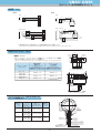
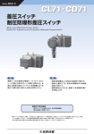
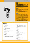
Cat.No. A99-01-N
CB33・CD75
圧力スイッチ
耐圧防爆形圧力スイッチ
Model CB33 Pressure Switch
Model CD75 Explosion-proof Construction Pressure Switch
概 要
Outline
本器は、耐久性・信頼性に重点を置いて設計・製作し
た接断差可調式の圧力スイッチです。ダブルスナップ
アクション(ベルビルスプリングの使用による)のた
め耐振性にすぐれ、現場形として、直接、機器の制御
に適しています。
This device is a dead-band adjustable pressure switch designed and
manufactured to ensure durability and reliability. It has excellent
vibration-proof characteristics thanks to its double snap action(using
Belleville spring) and is therefore ideal in the site for direct control of
equipment.
特 長
Features
・ベルビルスプリングの使用により耐久性・耐振性に
優れています。
(ダブルスナップアクション機構)
・接断差可調範囲が3〜20%max.P.です。但し、CB33
形圧力スイッチは圧力レンジ1.5〜15MPaのみ5〜
20%となります。
・設定は多回転(50回転/max.P.)で行うため、精密
設定が容易です。
・耐酸塗装仕上げのため、塩害による塗装面の錆び等
を防止します。
・ With the application of a Bellebille spring, this pressure switch
demonstrates excellent vibration resistance and durability. (Double
Snap Action Mechanism)
・ Adjustable range of dead-band is 3 to 20% max. P. However, CB33
pressure switch 5 to 20 % only 1.5 to 15 MPa.
・ Since setting is by multiple rotations (50 rotations / max. P.),
accurate setting is possible.
・ Acid-proof coating prevents rusting from salt damage.
推奨圧力設定範囲(CB33,CD75共通)
上限式:
(10%max.P.+接断差)
〜90%max.P.
下限式:10%max.P.〜
(90%max.P.−接断差)
Range of recommended pressure setting
(CB33 and CD75 commonness)
Upper limil type: (10%max.P.+Dead band)〜90%max.P.
Lower limit type: 10%max.P.〜90%max.P.−Dead band)
*圧力スイッチが、正確に、かつ寿命が長く機能する圧力設定範囲は圧力レンジ30〜65%です。また記載の接液部材質が測定する気体
・液体に適合したものであることをご確認下さい。
*To keep high accuracy and long life of pressure switch, pressure adjustable range should be 30 to 65% of pressure range. Please pay attention whether wetted
parts materials are suitable for gases or liquids to be measured or not.
CB33・CD75
圧力スイッチ・耐圧防爆形圧力スイッチ
製作仕様1
項
Specifications 1
目 Item
モデル
Model
測定流体
Fluid
内
CB33
一般プロセス用
CD75
耐圧防爆構造(ExdⅡB+H2 T4)
容
Description
CB33: General process use
CD75: Explosion-proof construction (Exd ⅡB+H2 T4)
気体又は液体(但し、凍結がないこと)
Gas or Liquid (No freezing)
CB33
Operating environment
通常の状態において、引火・爆発の原因となるような
可燃性ガス、または液体の存在のない場所
CD75 危険場所 詳細は耐圧防爆構造の説明欄を参照下さい。
CB33: Places where there are no inflammable liquids or gases
which may cause ignition or explosion under normal conditions.
CD75: Hazardous area (Refer to the explanation column of the
explosion-proof construction for details.)
取
付
CB33
パネル取付
Mounting
CD75
パネル取付、2Bパイプ取付
CB33: Panel mounting
CD75: Panel mounting, 2B pipe mounting
使用環境
接続ネジ
Connection
接液部材質
Wetted parts material
圧力レンジ
Pressure range
耐
圧
Proofpressure
使用温度範囲
Operating temperature
精
度
Accuracy
温度係数
Temperature cofficient
接断差
Dead band
スイッチ
Switch
接点数
Quantity of switch
設定方式
Setting system
電線取出口
Outlet for electric wire
ケース材質・外装
Case material, finishing
ケース構造
Case structure
チェック端子(オプション)
Terminal box (Option)
動作表示灯(オプション)
Operation lamp (Option)
質
量
Weight
G3/8B、G1/2B、Rc1/4、Rc1/2、1/4NPTメス、
1/2NPT(CD75のみ製作)
※記載のない接続ネジについては、お問合わせ下さい。
G3/8B, G1/2B, Rc1/4, Rc1/2, 1/4NPTFemale,
1/2NPT (CD75 only)
Please contact us about connection without the description.
ベローズ
タンク
株
Bellows: 316Lst.st.
Tank: 316st.st. or 316Lst.st. (Depends on pressure range)
Socket: 316st.st.
SUS316L
SUS316 又は SUS316L(圧力レンジにより異なる)
SUS316
CB33:0.01〜0.1→1.5〜15MPa
−0.1〜0MPa
CD75:0.01〜0.1→1〜10MPa
−0.1〜0MPa
CB33: 0.01 to 0.1 → 1.5 to 15 MPa
-0.1 to 0 MPa
CD75: 0.01 to 0.1 → 1 to 10 MPa
-0.1 to 0 MPa
0.15〜21MPa
0.15 to 21 MPa
(Depends on pressure range)
(圧力レンジにより異なる)
CB33
−20〜60℃
CD75
−5〜40℃
CB33
±0.5%max.P.
CD75
±1%max.P.
CB33: -20 to 60 ℃
CD75: -5 to 40 ℃
CB33: ±0.5%max.P.
CD75: ±1%max.P.
0.05%max.P./℃
0.05%max.P./℃
製作仕様2 参照
Specification 2 references.
マイクロスイッチ
Micro switch
1接点(一般用、直流用)又は2接点(同時作動)
One contact (Standard, direct current use) or two contact (Setting dual circuit)
内部調整式
Internal adjustment type
CB33
コンジットタイプ
CD75
耐圧パッキンタイプ
G1/2
CB33
ADC12・ブルー/グレー
CD75
AC7A・ブルー/グレー
CB33: Conduit G1/2
CD75: Proofpressure gasket
ツートン
ツートン
耐酸塗装
耐酸塗装
CB33: Aluminium alloy die casting (ADC12), Blue & Gray Epoxy painted
CD75; Aluminium alloy casting (AC7A), Blue & Gray Epoxy painted
IP65
IP65
接触抵抗などの測定時に電線を端子台から外し、テスタの端子
を手で押しあてていましたが、チェック端子付の場合、両端の
ネジを外すだけでテスタの端子が差し込める構造であるため、
測定時を安定させ、電線を端子台から取り外す手間を省くこと
ができます。(CB33のみ製作可能)
Although the wire used to have to be removed from the terminal
plate and the tester terminal pressed against it when measuring
contact resistance, with the provision of a check terminal, simply
remove the screws on the terminal plate and insert the terminals
of the tester. This ensures stability when measuring and eliminates
the trouble of removing the wire from the terminal plate. CB33 only
圧力スイッチの電源投入状態やマイクロスイッチの動作状態が
ひと目で確認できます。(CB33一般用、同時作動で製作可能
です。直流用は製作できません。)
*チェック端子と動作表示灯は同時取付出来ません。
The on/off state of the pressure switch and the operating state of
the microswitch can also be confirmed at a glance.
(It is possible at the time of the simultaneous operation of CB33
standard. Are not possible for direct current.)
* Terminal box and operation lamp cannot be installed simultaneously.
CB33
約2kg
CD75
約5kg
CB33: Approx. 2 kg
CD75: Approx. 5 kg
2
CB33・CD75
圧力スイッチ・耐圧防爆形圧力スイッチ
製作仕様2
Specifications 2
電気的特性:
Switch
1 contact
standard
125V AC
一接点直流用
1 contact
direct current
定
一接点一般用
二接点同時作動
2 contacts
simultaneous operation
スイッチ
Electric characteristics:
格
Rating
抵抗負荷
誘導負荷
Load resistance
Inductive load
20A
耐
電
絶縁抵抗
圧
Withstand voltage
Insulation resistance
20A
250V AC
20A
20A
125V DC
0.5A
0.05A
250V DC
0.25A
0.03A
125V AC
10A
6A
250V AC
3A
1.5A
125V DC
10A
6A
250V DC
3A
1.5A
125V AC
10A
6A
250V AC
10A
4A
125V DC
0.5A
0.05A
250V DC
0.25A
0.03A
2000V AC
500V DC
100MΩ以上
各端子とケース間
1分間
各端子とケース間
2000V AC
Between terminals
and case for 1 minute
500V DC
100MΩ or over
Between terminals
and case
・誘導負荷は、力率0.4以上(AC)
時定数7ms以下(DC)
※一接点直流用:一般用に対し、直流定格を増したもの。
・Inductive load: Power factor 0.4 or over (AC)
Time constant 7ms or less (DC)
※1 contact direct current: Direct current rating is bigger than standard.
圧力レンジと接断差・耐圧・接液部材質:
Pressure range, dead band, proofpressure and wetted parts material:
接 断 差
圧力レンジ
MPa
Dead band
Pressure range
(調整可能範囲)
耐圧
接液部材質
MPa
Proofpressure
(Adjustable range)
−0.1 〜0
0.003〜0.02
0.15
0.01〜0.1
0.003〜0.02
0.15
0.02〜0.2
0.006〜0.04
0.3
0.03〜0.3
0.009〜0.06
0.45
0.04〜0.4
0.012〜0.08
0.6
0.06〜0.6
0.018〜0.12
0.9
0.1 〜1
0.03 〜0.2
1.5
0.15〜1.5
0.045〜0.3
2.25
0.2 〜2
0.06 〜0.4
3
4.5
0.3 〜3
0.09 〜0.6
0.5 〜5
0.15 〜1
0.7 〜7
0.21 〜1.4
10.5
1
0.3
〜2
15
0.75 〜3
21
〜10
ベローズ
株
Tank
Bellows
Socket
SUS316L
SUS316L
SUS316
316Lst.st.
316Lst.st.
316st.st.
SUS316
316st.st.
7.5
SUS316
316st.st.
CB33 only
圧力レンジの選び方
調整範囲 Adjustable range
σ stress
σ応力
L Setting
MIN
H設定
H Setting
接断差
接断差
Dead band
2
・Set value is steady, accurately: 30%max.P. or over
・Longevity is good: 65%max.P. or less
・Accuracy, Longevity is good [Ideal]: About 30 to 65% of the adjustable ranges
Range 1.Selection of both accuracy and longevity
In the right figure
Range 2.Selection of valuing accuracy
Range 3.Selection of valuing longevity
Dead band
1
3
Range of recommended pressure adjustment
(CB33 and CD75 commonness)
0 10
Upper limil type: (10%max.P.+Dead band)〜90%max.P.
Lower limit type: 10%max.P.〜90%max.P.−Dead band)
25
50
圧 力
Pressure
3
Proof
pressure
H Setting
L Setting
上限式:(10%max.P.+接断差)〜90%max.P.
下限式:10%max.P.〜(90%max.P.−接断差)
How to choose pressure
MAX
H設定
MAX
L設定
MIN
L設定
推奨圧力調整範囲(CB33,CD75共通)
耐圧
降伏点
・設定値が正確で安定:30%max.P.以上
・寿命が良い所:65%max.P.以下
・正確、かつ寿命の良い所〔理想〕
:調整範囲の30〜65%位
右図に於いて 範囲1.精度・寿命両方の選定
範囲2.精度重視の選定
範囲3.寿命重視の選定
Yield point
1.5 〜15
※CB33のみ製作可能
Wetted parts material
タンク
75
90 100%
CB33・CD75
圧力スイッチ・耐圧防爆形圧力スイッチ
外形寸法1
Dimensions 1
単位/Unit:mm
CB33
8-φ6取付穴
φ10
69
77
120
11 11 11
8-φ6 Mounting hole
For range 0.3MPa or less
φ5.5
69
ブラケット
13
22
145
35
111111
NAGANO KEIKI
レンジ0.3MPa以下の場合
G1/2
電線管接続口
Bracket
For range 0.3MPa or less
20
Electric wire tube connection port
G1/2B
36
φ5
圧力レンジ
3
35
24X27.7六角
0.4,0.6,1,1.5,2,3MPaの時
Pressure range 0.4, 0.6, 1, 1.5, 2, 3MPa
149
133
24X27.7Hex.
24 Flats
φ5
G1/2B
3
φ5
G1/2B
20
24二面幅
24X27.7Hex.
20
24x27.7六角
3
(130.8)
26.5
96
81
レンジ0.3MPa以下の場合
(23.5)
92
8
φ82
圧力レンジ
圧力レンジ
5,7,10,15MPaの時
Pressure range 5, 7, 10, 15MPa
0.2,0.3MPaの時
149
160
Pressure range 0.2, 0.3MPa
24x27.7六角
φ5
φ91
φ91
G1/2B
圧力レンジ
φ5
G1/2B
−0.1MPaの時
圧力レンジ
Pressure range -0.1MPa
0.1MPaの時
Pressure range 0.1MPa
*印寸法は圧力レンジ0.1MPa
にも適用する
Dimensions marked with * are also
applied to 0.1MPa
オプション
Option
ネオンランプ
又はLED
Neon lamp or LED
4
3
55*
3
*42
20
24X27.7Hex.
20
24X27.7Hex.
24x27.7六角
CB33・CD75
圧力スイッチ・耐圧防爆形圧力スイッチ
外形寸法2
Dimensions 2
単位/Unit:mm
CD75
パネル取付
Panel mounting
圧力レンジ Pressure range
0.4,0.6,1,1.5,2,3MPa
114
(120)
φ104
10
117
70
端子箱
20
7.5
Proofpressure packing type
54
3
φ5
φ10
耐圧パッキンタイプ
24x27.7六角
G1/2B
24x27.7 Hex.
Pressure range
(119)
圧力レンジ
5,7,10MPa
圧力レンジ
−0.1MPa
φ5.5
φ104
(274.5)
40.5
(131)
94
148
80
102
40 27
(91)
Terminal box
Pressure range
24二面幅
20
24 flats
(146)
3
φ5
G1/2B
24x27.7六角
20
*
42
φ5
φ91
G1/2B
(133)
*印寸法は圧力レンジ0.1MPa
にも適用する
24x27.7六角
3
20
Dimensions marked with * are also
applied to 0.1MPa
24x27.7 Hex.
φ5
G1/2B
φ91
2Bパイプ取付
(162)
2B pipe mounting
104
10
(120)
117
70
7.5
40.5
2Bパイプ
33.75
27
G1/2B
3
φ5.5
94
(112)
102
φ10
(148)
80
40 27
(200.5)
104
レンジ Range
0.1,0.2,0.3MPa
2B pipe
φ5
M8
24x27.7六角
24x27.7 Hex.
5
(98)
(136)
3
圧力レンジ
0.1MPa
24x27.7 Hex.
CB33・CD75
圧力スイッチ・耐圧防爆形圧力スイッチ
結線図
Wiring
CB33
CD75
1SW
1SW
N.O.
INC.
N.O.1 *
COM.
N.O.
INC.
COM.1
N.C.
DEC.
COM.
N.C.1
N.C.
DEC.
マイクロスイッチ
Micro switch
COM.
*
N.C.
N.O.
マイクロスイッチ
Micro switch
ターミナル
Terminal
ターミナル
Terminal
2SW(D.P.D.T.)
2SW(D.P.D.T.)
N.O.
N.O.
INC.
COM.
N.C.
COM.1
N.C.
N.O.2
COM.
COM.2
N.C.
マイクロスイッチ
Micro switch
COM.1
N.C.1
N.O.1
COM.2
N.C.1
N.O.
DEC.
INC.
N.O.1
COM.
N.O.2
N.O.
N.C.2
N.C.2
ターミナル
Terminal
COM.
N.C.
DEC.
ターミナル
Terminal
マイクロスイッチ
Micro switch
*1接点直流用S.P.D.T.仕様の場合は、
(+)
極性を共通端子COM1に接続して下さい。
Please connect the (+) polarity with common terminal COM1 for S.P.D.T. specification for 1 point of contact direct current.
CB33 オプション
Option
21
Outside dia. size of the installed wire tube connector can be enlarged by installing joint of the option with pressure range.
MPa
Pressure range
オプションツギテ
G1/2装着時
Wire tube connection port
Standard G1/2
Option joint
When G1/2 is installed
52
15
(23)
14
電線管コネクタ外径(mm)
電線管コネクタ外径(mm)
オプションツギテ(G1/2)
Outside dia. of wire tube connector
Outside dia. of wire tube connector
Option joint (G1/2)
φ29以下 or less
φ48以下 or less
φ37以下 or less
φ60以下 or less
−0.1 〜0
0.01〜0.1
0.02〜0.2
0.03〜0.3
0.4以上 or over
(60)
圧力レンジ
電線管接続口
標準 G1/2
φ26
圧力レンジにより、オプションのツギテを装着することで、取り付けられる電線管
コネクタの外径サイズを大きくすることが可能です。
G1/2B
φ15
27x31.2六角
Wire pipe
27x31.2Hex.
電線管
15
G1/2
φ73以下 or less
オプションツギテ
Option joint
(63.5)
オプションツギテ(G1/2)装着時
Option joint when G1/2 is installed
CD75 電線取出口
Outlet for electric wire
コンジット
接続ネジ
パッキン内径
(d)φ
適用ケーブル
外径 φ
保護管
接続ネジ
Conduit
connection
Gasket inside
diameter(d) DIA.
Applicable cable
outside diameter DIA.
Protection tube
connection
G1/2
φ8〜φ12
(φ1毎に選択)
φ7.0〜φ12.0
G1/2
端子箱
Terminal box
(Available in 1DIA. steps)
G3/4
φ13〜φ16
(φ1毎に選択) φ12.0〜φ16.0
座金
G3/4
Washer
(Available in 1DIA. steps)
G1
φ17〜φ20
(φ1毎に選択) φ16.0〜φ20.0
G1
リングパッキン
Ring packing
(Available in 1DIA. steps)
M3トメネジ
M3 set screw
ケーブル保護管接続ネジ
Cable protection tube
connection
6
ケーブルグランド
Cable grand
ケーブルクランプ
Cable clamp
ケーブル外径
Cable outside diameter
CB33・CD75
圧力スイッチ・耐圧防爆形圧力スイッチ
耐圧防爆
Explosion-proof
耐圧防爆構造:Explosion-proof construction:
耐圧防爆型式認定:(CD75)Explosion-proof type approval: (CD75)
労働省告示による、国際規格IECに整合した技術的基準
及び新・防爆指針にのっとった認定を取得しています。
耐圧防爆構造とは、全閉構造で容器内部で爆発性ガス
が爆発した場合でもその爆発圧力に耐え、且つ外部の爆
発性ガスに引火する恐れのない構造をいいます。
この方針に基づき製作された弊社の差圧スイッチは工
場、その他の事業所において可燃性ガスまたは可燃性液
体の蒸気が存在する恐れのある場所での圧力計測にご
使用頂けます。
Approval is obtained in conformity with technical standards matched to
IEC international standards by the Ministry of Labor Notification and new
explosion-proof policy.
型式名称
型式検定合格番号
Type name
Type approval number
CD75
第TC1 4 3 3 7 号
No. TC14337
Explosion-proof construction is a totally-enclosed construction such that even if
an explosive gas explodes inside the container, the container will withstand the
force of the explosion and there is no danger of ignition by external explosive
gases. Our differential pressure switches manufactured under this policy are
used in pressure measurements where inflammable gas or the inflammable gas
vapors may exist in factories and business offices.
Exd Ⅱ B+H2 T4 について:
Ex
d
Ⅱ B+H2
T4
温度等級を示す
Indicates the temperature class.
グループ分類(ⅡBグループに水素ガスも含む)
Group classification (II B group includes hydrogen gas.)
耐圧防爆構造を示す記号
Symbol indicating explosion-proof construction
防爆構造であることを示す記号
Symbol indicating explosion-proof construction
グループ分類
Group classification
防爆電気機器の種類は使用される場所によってグループⅠとグループⅡに分類されます。
本器はグループⅡに属しており、鉱山事業所坑内の危険場所を除く工場、又は事業所の危険場所において使用する機器に
該当します。
Explosion-proof electrical equipment are classified into GroupⅠand GroupⅡby the place where they are used. The CL70/CD70 belong to GroupⅡ, and
come under equipment used in hazardous areas of factories and business offices, except hazardous areas in mines.
適用できるグループ区分とガス又は蒸気の分類
Applicable group and classification of gas or steam
ガス又は蒸気の分類
適用できるグループ
Classification of gas or steam
Applicable group
ⅡA
A
B
ⅡB
ⅡC
ⅡB
ⅡC
ⅡC
C
T4の適用できるガス又は蒸気の発火温度
Ignition point of gas or steam which T4 can apply
ガス又は蒸気の発火温度
適用できる温度等級
Ignition point of gas or steam
Applicable temperature class
450℃を超えるもの/Higher than 450℃
T1 T2 T3 T4 T5
T6
300℃を超えるもの/Higher than 300℃
T2 T3 T4 T5
T6
200℃を超えるもの/Higher than 200℃
T3 T4 T5
T6
135℃を超えるもの/Higher than 135℃
T4 T5
T6
100℃を超えるもの/Higher than 100℃
T5
T6
85℃を超えるもの/Higher than 85℃
T6
適用できるガス又は蒸気の一例
Example of applicable gas or steam
温度等級
グループ
T1
Temperature
class
Group
ⅡA
アセトン Acetone
アンモニア Ammonia
一酸化炭素 Carbon monoxide
エタン Ethane
酢酸 Acetic acid
酢酸エチル Ethyl acetate
トルエン Toulene
プロパン Propane
ベンゼン Benzene
メタノール Methanol
メタン Methane
T2
T3
エタノール
ヘキサン
アセトアルデヒド
Ethanol
Hexane
Acetaldehyde
T6
1-butanol
ブタン
Butane
エチルメチル
エーテル
Ethylene
エチレンオキシド
Ethyl methyl
ether
Ethylene oxide
ⅡC
T5
1-ブタノール
エチレン
ⅡB
T4
水素
アセチレン
二硫化炭素
硝酸エチル
Hydrogen
Acetylene
Carbon bisulfide
Nitric acid ethyl
7
CB33・CD75
圧力スイッチ・耐圧防爆形圧力スイッチ
形番構成
Model number configuration
モデルNo.
ご用命に際しては、形番、各仕様及び圧力レンジをご指定ください。
For ordering, please specify the model number, each specs and the range.
Model name
3
C B 3 3
圧力スイッチ
①
②
B
③
④
⑤
⑥
⑦
⑧
⑨
⑩
⑪
⑫
⑬
⑭
⑮
Pressure Switch
形番
選択仕様
Model number
①
スイッチ
Switch
付加仕様
(オプション) Additional spec. (Option)
Selective spec.
0
接断差可調式
1接点
一般用S.P.D.T.
Dead band adjustable type 1 contact standard S.P.D.T.
1
接断差可調式
1接点
直流用S.P.D.T.
Dead band adjustable type 1 contact direct current S.P.D.T.
2
接断差可調式
2接点
同時作動D.P.D.T.
②
接続ネジ
Connection
3
G3/8B
4
G1/2B
7
Rc1/4
9
Rc1/2
X
1/4NPTメス
その他指定
3
③
接液部材質
Dead band adjustable type 2 contacts simultaneous operation D.P.D.T.
1/4NPT female
Others
株:SUS316、ベローズ:SUS316L
Socket: 316st.st., Bellows: 316Lst.st.
Wetted parts materials
④
圧力レンジ(MPa)
レンジコードを選定の上、
圧力レンジ及び単位を別途
ご指定下さい。
Pressure range
Please specify the pressure range
and units separately besides
selection of range code.
1
−0.1〜0
2
0.01〜0.1、0.02〜0.2、0.03〜0.3
3
0.04〜0.4、0.06〜0.6、0.1〜1、0.15〜1.5、0.2〜2、0.3〜3
4
0.5〜5、0.7〜7、1〜10、1.5〜15
⑤
接点形式・接点数
Type of contacts /
quantity of switch
A
H :上限1接点
H: Upper limit type with 1 contact
B
L :下限1接点
L: Lower limit type with 1 contact
D
2H:同時作動
上限2接点
2H: simultaneous operation Upper limit type with 2 contacts
E
2L :同時作動
下限2接点
2L : simultaneous operation Lower limit type with 2 contacts
その他指定
⑥
スイッチ
Others
0
標準形
3
標準形+金メッキ(直流用は製作不可)
Standard
Standard + gold plated (Not possible for direct current)
Switch
その他指定
B
⑦
電線取出口
Others
コンジット
G1/2
その他指定
Others
Conduit type G1/2
Outlet for electric wire
⑧
処理
Treatment
⑨
付加仕様
0
ナシ
1
禁油処理
Use no oil
2
禁水処理
Use no water
3
禁油・禁水処理
Use no oil & water
0
ナシ
Nil
1
アリ
Required
Additional
specifications
(ご希望のものを別途ご指示下さい。)
・チェック端子付端子台
・動作表示灯 LED付(24V DC)
・動作表示灯 ネオンランプ(110V AC)
・動作表示灯 ネオンランプ(220V AC)
・原子力指定
・ブラケット
・外装指定
推奨圧力設定範囲
上限式:
(10%max.P.+接断差)
〜90%max.P.
(90%max.P.−接断差)
下限式:10%max.P.〜
(Please specify the desired documents separately.)
・Terminal stand with check terminal
・Operation lamp with LED (24V DC)
・Operation lamp with neon lamp (110V AC)
・Operation lamp with neon lamp (220V AC)
・Nuclear power specification
・Bracket
・Coating specification
Range of recommended pressure setting
Upper limil type: (10%max.P.+Dead band)〜90%max.P.
Lower limit type: 10%max.P.〜90%max.P.−Dead band)
「製作範囲」
・設定方式:内部調整式
⑮
ドキュメント
Manufacturing range
・Setting system: Internal adjustment type
Documents
0
ナシ
Nil
1
アリ
Required
(ご希望のものを別途ご指示下さい。)
提出図、取扱説明書、検査要領書、
ミルシート、検査成績表(1個1部)、
検査・トレサビリティ証明書、立会検査
(Please specify the desired documents separately.)
Submission drawings, instruction manual,
inspection procedure, mill sheet, test report (1 pc 1 copy),
inspection / traceability certificate,
attended inspection
※旧型モデルをご希望の場合は、別途ご指定下さい。
Please specify it separately when you hope for the old model.
※仕様項目がない場合は、
Nil
をご指定ください。
Specify "X" if there is no specification item.
8
CB33・CD75
圧力スイッチ・耐圧防爆形圧力スイッチ
形番構成
Model number configuration
モデルNo.
ご用命に際しては、形番、各仕様及び圧力レンジをご指定ください。
For ordering, please specify the model number, each specs and the range.
Model name
C D 7 5
耐圧防爆形圧力スイッチ
①
②
③
④
⑤
⑥
⑦
⑧
⑨
⑩
⑪
⑫
⑬
⑭
⑮
Explosion-proof Construction Pressure Switch
形番
選択仕様
Model number
①
取付形態
付加仕様
(オプション) Additional spec. (Option)
Selective spec.
3
パネル取付、耐圧パッキンタイプ
7
2Bパイプ取付、耐圧パッキンタイプ
Panel mounting, Proofpressure packing type
2B pipe mounting, Proofpressure packing type
Mounting
②
接続ネジ
Connection
3
G3/8B
4
G1/2B
7
Rc1/4
9
Rc1/2
M
1/2NPT
X
1/4NPTメス
その他指定
③
スイッチ
Switch
1/4NPT female
Others
0
1接点一般用
(S.P.D.T.)
1 contact standard (S.P.D.T.)
1
1接点直流用
(S.P.D.T.)
1 contact direct current (S.P.D.T.)
2
2接点同時作動
(D.P.D.T.)
④
圧力レンジ(MPa)
レンジコードを選定の上、
圧力レンジ及び単位を別途
ご指定下さい。
Pressure range
Please specify the pressure range
and units separately besides
selection of range code.
2 contacts simultaneous operation (D.P.D.T.)
1
−0.1〜0
2
0.01〜0.1、0.02〜0.2、0.03〜0.3
3
0.04〜0.4、0.06〜0.6、0.1〜1、0.15〜1.5、0.2〜2、0.3〜3
4
0.5〜5、0.7〜7、1〜10
⑤
接点形式・接点数
Type of contacts /
quantity of switch
A
H :上限1接点
H: Upper limit type with 1 contact
B
L :下限1接点
L: Lower limit type with 1 contact
D
2H:同時作動
上限2接点
2H: simultaneous operation Upper limit type with 2 contacts
E
2L :同時作動
下限2接点
2L : simultaneous operation Lower limit type with 2 contacts
その他指定
⑥
スイッチ
Others
0
標準形
3
標準形+金メッキ(直流用は製作不可)
Standard
Standard + gold plated (Not possible for direct current)
Switch
その他指定
⑦
電線取出口
Outlet for electric wire
Others
イ
G1/2 × パッキン内径 8mm
ウ
G1/2 × パッキン内径 9mm
G1/2 x Gasket inside 9mm
エ
G1/2 × パッキン内径 10mm
G1/2 x Gasket inside 10mm
オ
G1/2 × パッキン内径 11mm
G1/2 x Gasket inside 11mm
カ
G1/2 × パッキン内径 12mm
G1/2 x Gasket inside 12mm
ケ
G3/4 × パッキン内径 13mm
G3/4 x Gasket inside 13mm
コ
G3/4 × パッキン内径 14mm
G3/4 x Gasket inside 14mm
サ
G3/4 × パッキン内径 15mm
G3/4 x Gasket inside 15mm
シ
G3/4 × パッキン内径 16mm
G3/4 x Gasket inside 16mm
タ
G 1 × パッキン内径 17mm
G1 x Gasket inside 17mm
チ
G 1 × パッキン内径 18mm
G1 x Gasket inside 18mm
ツ
G 1 × パッキン内径 19mm
G1 x Gasket inside 19mm
テ
G 1 × パッキン内径 20mm
G1 x Gasket inside 20mm
⑧
処理
Treatment
⑨
付加仕様
0
ナシ
1
禁油処理
Use no oil
2
禁水処理
Use no water
3
禁油・禁水処理
上限式:
(10%max.P.+接断差)
〜90%max.P.
下限式:10%max.P.〜
(90%max.P.−接断差)
⑮
ドキュメント
Range of recommended pressure setting
Documents
Upper limil type: (10%max.P.+Dead band)〜90%max.P.
Lower limit type: 10%max.P.〜90%max.P.−Dead band)
Nil
0
ナシ
1
外装指定
Additional
specifications
推奨圧力設定範囲
G1/2 x Gasket inside 8mm
Use no oil & water
Nil
Coating specification
0
ナシ
Nil
1
アリ
Required
(ご希望のものを別途ご指示下さい。)
提出図、取扱説明書、検査要領書、
ミルシート、検査成績表(1個1部)、
検査・トレサビリティ証明書、立会検査
(Please specify the desired documents separately.)
Submission drawings, instruction manual,
inspection procedure, mill sheet, test report (1 pc 1 copy),
inspection / traceability certificate,
attended inspection
※仕様項目がない場合は、
をご指定ください。
Specify "X" if there is no specification item.
9