1
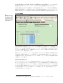
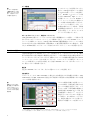
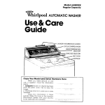
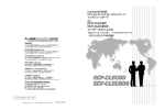
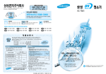
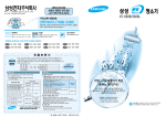
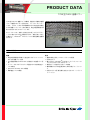
PRODUCT DATA
7799 型 PULSE 音響パワー
7799 型 PULSE™ 音響パワーは機械、装置および器具の音響
パワーや音響エネルギーを計測する、ソフトウェアパッケー
ジです。これは、さまざまな環境条件における音圧法の測定
および音響インテンシティ法の測定を、現在の国際規格に準
拠して実行するようにサポートします。
本ソフトウェアは、選択した測定方法に従ってガイドがウィ
ンドウに表示され PULSE を動作させます。測定が完了すると
計算を行い、Microsoft® Excel ファイルに測定結果を自動保
存します。
用途および利点
用途
利点
• 現在の国際規格に準拠した音圧法およびインテンシティ
• 複数の測定方法を1つのソフトウェアで提供
• 計測をガイド
• 親しみやすい Microsoft® Excel のワークブックフォーマッ
•
•
•
•
法による音響パワー計測
EU 騒音放射指令 2000/14/EC で規定される音響パワー計
測
オペレータおよびバイスタンダ位置における放射音圧レ
ベルの測定
prominent discrete tone の識別
衝撃音圧レベルの検出
トによりカスタマイズできるレポート
• 現場でデータ比較が行えるデータ管理
• 標準試験および不適合解決のための共通プラットフォー
ム
• 必要に応じて計測点数を可変できるスケーラブルソ
リューション
はじめに
騒音放射の値は、機械、装置、器具の市場における差別化の項目の1つになりつつあります。つ
まり低い騒音放射とは製品を使用するユーザーとバイスタンダ(傍観者)に対するより低い騒
音暴露を意味します。個人であったり法人であったりするお客様はこの騒音放射の値を評価す
るので、購入を決定する場合にその製品の騒音放射表示をより意識することになります。
従業員にとって、一般の作業環境での機械騒音が与える影響が問題になります。規制または従
業員満足レポートの一方に義務付けられて、作業現場を計画し配備する場合に騒音暴露レベル
が適合していることを、雇用者は保証しなければなりません。欧州騒音制御の枠組みの中で、指
令 2003/10/EC「物理要因、騒音」は、作業装置の製造業者によって提供される騒音放射の情報
と騒音放射を低減するために設計された代案的作業装置の存在に注意を払うことを雇用者にさ
え要求しています。
結果として、製造業者は競合に打ち勝つために自社製品の騒音放射を低減する方法を見つけな
ければなりません。ある種の製品、例えば作業場用機械などの場合には、これらの要求は法的
な要求によって複合化されています。例えば、EU 域内市場参入を計画された移動部分を伴う任
意の機械に適用される、
「機械」指令 98/37EEC は機械の取扱説明書に放射音圧レベルの振幅に
依存して放射音圧レベルまたは音響パワーを含めることを要求しています。別の例では、EU に
おける屋外使用の装置 57 種の指定機種を販売する製造業者に「屋外装置の騒音放射」指令 2000/
14/EC は保証される音響パワーレベル、つまり(製造の変動と測定方法に起因する)不確かさ
を加算された音響パワーレベルにて、これらの機械にマークすることを要求するため、製造業
者はこれらの値を越えないことを確認しなければなりません。およそ 20 種類の装置が音響パ
ワーの制限を受けています。
音響パワーは、製品の騒音放射を表示する場合に測定すべき推奨量になってきました。その理
由は、この値が絶対量であり、騒音発生源自身にのみ依存するもので、音響環境と無関係であ
るからです。
また、放射音圧レベルも、主としてその表示目的のために、騒音放射の表示として利用されま
す。これは、機械のオペレータ位置または機械周辺の明確に定義された他の位置に対する、機
械からの直接的音響放射を測定するものです。音圧レベルは騒音発生源と測定する音響環境の
両方に依存するため、特定の騒音試験方法がマイクロホンの正確な位置や試験環境の特性を定
義しています。
製品の音や音質を議論する場合、対象となる騒音放射だけでなく、聴取者に対して大きな不快
の原因となる音の特徴、例えば“prominent discrete tone”と“衝撃騒音”があります。discrete
tone は顕著な単一周波数の可聴音で、衝撃騒音は短い持続時間でかつ比較的大きい振幅の騒音
です。
7799 型の利点
多数の方法を1つのソリューションで提供
音響パワーは以下の3つの方法に基づいて計測され算出されます:
1. 自由音場(または準自由音場)における音源によって発生される音圧を測定し、次に音圧測
定から音響パワーを計算する。
2. 1と同様であるが、拡散音場で測定する。
3. 音源の音響パワーを計測するために、任意の音場における音響インテンシティを直接測定す
る。
2
音圧法は製造検査や大量の試験(情報および通信機器のための特定規格によって)のために比
較的頻繁に使われます。一方、インテンシティ法は一般的に現場測定のために使われます。
お客様が選択される方法とは無関係に、7799 型 PULSE 音響パワーは、最も共通の国際規格に
準拠する音源の音響パワーを決定するために、必要な測定をお客様にガイドします。また、作
業現場の放射音圧レベル、prominent discrete tone の検出、衝撃騒音の同定の測定を提供します。
ガイドされる測定
図1
自由音場における音圧法
のワークブック。この例
では、測定は1つのボタ
ン操作で囲う表面上のす
べてのマイクロホン位置
で同時に実施される。
7799 型の明確かつ直感的ユーザインタフェースは各規格に基づく測定によって、規則的に、業
界またはブランド仕様、要求を満たすように、ガイドします。事前定義された Microsoft® Excel
ワークブックを組み込むことで、7799 型のインタフェースはデータ収集、比較、保存、報告の
ために親しみやすい環境を提供します。
例えばポップアップテキスト、カラー表示、警告などのグラフィカル機能は、測定状態、保留
行為の決定、規格内の指定パラメータの検証について迅速な更新を可能にします。プログラム
の柔軟性があるため、繰返し作業のスキップや、試験セットアップと実行中の問題領域を正確
に指摘することが可能です。
カスタマイズできるレポート
デフォルトのレポートテンプレートは Microsoft® Excel ワークブックに含まれるため、ボタン
をクリックするだけでレポートを作成できます。レポートに測定結果のグラフを埋め込むため
に、Create Graph ボタンをクリックし1、関連データを選択します。作成されたレポートは会社
のスタイルや個人の流儀に合わせてデフォルトのレイアウトをカスタマイズでき、自在性を備
えた試験を利用するように同一の標準パラメータを適用します。また、独自の報告書テンプレー
トを作成し保存することも可能です。
1. 自由音場条件における音圧法測定の場合にのみ利用可能。7767 型 PULSE データマネージャのライセンスが必要。
3
データ管理
ディスクにファイルを保存することに
加えて、7799 型は大量のデータを保存
するために専用データベースを提供し
ます1。PULSE データマネージャに統
合された Microsoft® SQL データベー
ス技術によって、すべての PULSE プ
ラットフォームにまたがる現場での
データ検証や比較を容易に行えます。
データベースへの保存データは、バッ
チ測定の統計レポートの作成、平均値
と標準偏差の計算など、さらにデータ
共 有 の 促 進、ト レ ー サ ビ リ テ ィ の サ
ポートなども可能になります。
図2
データベース利用の例:
3種類の音響パワーの結
果をデータベースから抽
出し、下側のディスプレ
イに重ねて表示する。
スケーラブルソリューション、共通プラットフォーム
7799 型 PULSE 音響パワーソフトウェアはさまざまな機器構成によって動作し、ご予算やご要
求に合わせてスケーラブルにソリューションを構築できます。パワフルな PULSE プラット
フォーム上に構築しているので、7799 型と他の PULSE 音響振動測定アプリケーションの組み
合わせは完全かつ自在な製品試験を、規格準拠や、不適合問題を解決するのに最適です。必要
に応じ、PULSE 製品、アプリケーションと組み合わせることにより、システムを拡張できます。
ソフトウェア概要
3種の事前定義された PULSE プロジェクトが提供されます。これらのプロジェクトは 3 種の
異なる測定状況に必要な典型的な機器設定を含みます。これらは簡単に特定の測定の要求に合
うようにカスタマイズすることができます。個別のプロジェクトは複数の事前定義された Excel
ベースワークブックにより使い始めることができ、このワークブックは測定ユーザインタ
フェースと報告用ツールの両方に利用します。任意の PULSE プロジェクトまたはテンプレート
は、保存しておいて再利用できます。
音圧法
音圧法の PULSE プロジェクトは、以下の 3 種のワークブックを提供します:
自由音場法:
このワークブックは、ISO 3745:2003 に規定される無響室または半無響室と同様に、ISO
3744:1994 または ISO 3746:1994 に規定される反射面上の本質的に自由音場条件における音響
パワーの計測に適用されます。
図3
複数マイクロホン位置:
囲う表面上の 10 個のマイ
クロホンに加えてワーク
ステーションの 4 個のマ
イクロホンにおける同時
測定の例
これらの規格に準拠する音響パワーレ
ベルの計測は、音源を囲う表面上の音
圧レベルの測定を必要とします。マイ
クロホンの数、分析周波数の範囲およ
び利用可能な PULSE のビート数(信
号処理能力)に依存して2、このような
測定はすべてのマイクロホン位置にお
いて同時に、または数ステップに分け
て、測定を実施することが可能です。
選択された規格によって必要なマイク
1. 自由音場条件における音圧法測定の場合にのみ利用可能。7767 型 PULSE データマネージャのライセンスが必要。
2. ビート数の情報については、PULSE ソフトウェアプロダクトデータ(BU 0229)を参照ください。
4
ロホンの数が利用可能なマイクロホンの数を超える場合には、測定中にマイクロホンまたは試
験対象を移動させる方法を利用できます。
残響室用ワークブック
このワークブックは、ISO 3741:1999 に規定される残響室と同様に、ISO 3743:1994 または ISO
3743-2:1994 に規定される残響音場における音響パワーの計測に適用されます。
このインタフェースは自由音場条件でマイクロホンアレイと移動マイクロホンの両方の方法を
サポートします。このプログラムは狭帯域幅 /discrete tone の存在を評価し、選択した規格を満
たすために必要な、追加のマイクロホンおよびまたは音源の位置について決定するように、ユー
ザーをガイドします。
EU 指令 2004/14/EC
このワークブックは、屋外用 57 種の装置の環境における騒音放射に関する EU 指令 2000/14/
EC の条件を満たす、音響パワー計測用です。
含まれる各種の装置について、この指令は推奨される基本騒音放射規格に加えて、試験面積、測
定表面、マイクロホン位置の数を規定します。これらの装置において必要とされる各種の動作
環境については、指令は各稼動条件において測定から音響パワーを計算するための式を提供し
ます。
この EU 指令は製造の変動と測定方法に起因する不確かさの推定を必要とします。よって、製
造ラインのサンプリング方法が適用されることになります。
このソフトウェアは、測定表面、マイクロホン位置の数、稼動条件ごとに中間結果の計測、音
響パワーレベルの計算に関する、任意の要求をサポートするために、必要なすべての自在性を
提供します。
放射 SPL による音圧法
この PULSE プロジェクトは、放射音圧レベル(SPL)による自由音場法のワークブックを含み
ます。
これは、また、ISO 7779:1999 および ECMA 74(8th edition) の両方に準拠する TNR(Tone-toNoise Ratio) の判定基準、ECMA 74(8th edition) に準拠する PR(Prominence Ratio) 法、およ
び ISO 7779:1999 および ISO 11201:1995 に準拠する衝撃騒音の検出に基づく prominent discrete
tone の自動同定を提供します。
オペレータまたはバイスタンダ位置の任意数で測定できます。マイクロホンの数、分析周波数
の範囲および利用可能な PULSE ビート数(信号処理能力)に依存して、測定などはすべての位
置(音響パワー計測の測定を含めて)で同時に、または数ステップに分けて、測定を実施する
ことが可能です。
インテンシティ法
この PULSE プロジェクトは1つのインテンシティワークブックを含みます。このワークブック
は、ISO 9614-2:1996 に準拠するスキャニングによる音響インテンシティ測定を用いた音響パ
ワー計測のためのものです。
ツリー構造は、新しいユーザー定義の平面を追加することで、さらに以前に定義された平面を
セグメント化(分割化)することで、測定表面のジオメトリを編集することができます。平面
は希望精度を得るために最大 7 回まで小さく分割化できます。
5
測定に利用される、音圧残留インテンシティ指数は計算され、ダイナミック能力指数は保存さ
れます。測定表面に対する、表面音圧インテンシティインジケータ,FpI と負の部分パワーイン
ジケータ,F + / −は計算され、規格の要求と比較されます。これらの測定は自動的に記録され、
後でツリー構造または手動にて、個々の測定位置の状況をディスプレイに示します。
6
仕様 – 7799 型 PULSE 音響パワー
7799 型は PULSE のアプリケーションです。
システム要求事項
PULSE の PC 要求仕様を満たしていること
以下のライセンスが必要:
– 7771 型 PULSE CPB 分析
または
– 7700 型 PULSE FFT および CPB 分析(prominent discrete tone の同定用)
校 正
校正は PULSE 内蔵のキャリブレーションマスターによって実施され、1つのマ
イクロホンから次に校正器を移動させながら、自動的に校正を開始します。ト
ランスデューサの校正履歴はトランスデューサデータベースに残すことがで
き、一定時間間隔にわたる校正データの変動を監視できます。グローバルキャ
リブレーションは校正データベースを構築し、すべての PULSE プロジェクトに
おいて共有できます。
– Microsoft® Office 2000(または以降のバージョン)
1400 × 1050 ピクセルの画面分解能(または以上)を推奨
Free-field Method Workbook
Provides measurement and calculation procedures for the determination
of the sound power of noise sources as described in the following
international standards.
STANDARDS
CALCULATION
L pf
LW
ISO 3744:1994
DI i
ISO 3745:2003
Qi
ISO 3746:1995
Non-standard sound power determination is available via non-standard
surface time-averaged sound pressure level
sound power level
a
a
directivity index
directivity factor
a. Subscript i means that the quantity is measured or calculated at the ith microphone
position over the measurement surface
projects
SUITABLE TEST ENVIRONMENTS
• Anechoic or hemi-anechoic rooms as specified in ISO 3745:2003
Quantities Specific to ISO 3744 and ISO 3746:
L′ p ( B )
• Essentially free-field over a reflecting plane as specified in ISO
3744:1994
the measurement surface
L′ p ( S )
MEASUREMENT
L′ p ( B ) i a
time-averaged sound pressure level produced by
background noise
L′ p ( S ) i
a
a. Subscript i means that the quantity is measured or calculated at the ith microphone
position over the measurement surface
Quantities Specific to ISO 3745:
single-event sound pressure level produced by background
noise
L′ E ( S ) i
a
mean measured time-averaged sound pressure level for the
noise source under test over the measurement surface
K1
background noise corrections for the surface sound pressure
level
time-averaged sound pressure level from the noise source
under test
L′ E ( B ) i a
mean measured time-averaged background noise level over
single-event sound pressure level from the noise source
under test
a. Subscript i means that the quantity is measured or calculated at the ith microphone
position over the measurement surface
• All quantities are measured in 1/3-octave band for any range with
nominal midband frequencies from 50 Hz to 20 kHz1 or in 1/1-octave
band for any range with nominal midband frequencies from 63 Hz to
16 kHz
• A-weighted values calculated from 1/1-octave or 1/3-octave values as
specified in Annex H of ISO 3745:2003, or directly measured using Aweighting filter
• Simultaneous measurements can be made at all microphone positions
Quantities Specific to ISO 3745:
K 1i a
background noise corrections
L pi
sound pressure level corrected for background noise
a
L′ W
sound power level under different meteorological conditions
LE n
mean single-event sound pressure level over the
measurement surface for the nth working cycle
LE b
mean single-event sound pressure level over the
measurement surface and over a number of single working
cycles of equal duration
LJ
b
sound energy level
a. Subscript i means that the quantity is measured or calculated at the ith microphone
position over the measurement surface
b. PULSE Data Manager Type 7767 license required
• All quantities are calculated as overall A-weighted levels. 1/3-octave
band or 1/1-octave band level available depending on measurement data
VALIDATION
Criterion for background noise
or through successive steps when the number of microphone positions
Requirement evaluation for additional microphone positions
required by the selected standard is greater than the available number
STATISTICS3
of microphones, or the number of beats is not enough2
Mean and standard deviation of any measured or calculated quantity on
batch measurements
1. If microphone frequency range and available number of beats allow. For information
on microphone frequency range, please refer to the respective microphone Product
Data. Correction for absorption of sound by the atmosphere has to be made using
PULSE language
2. For information on the number of beats, please refer to the Software for PULSE
Product Data (BU 0229)
3. PULSE Data Manager Type 7767 license required
7
Reverberation Room Workbook
Provides measurement and calculation procedures for the determination
of the sound power of noise sources using the comparison method as
described in the following international standards.1
band for any range with nominal midband frequencies from 63 Hz to
16 kHz.
• A-weighted values calculated from 1/1-octave or 1/3-octave values as
specified in Annex H of ISO 3745:2003, or directly measured using A-
STANDARDS
ISO 3741:1999
ISO 3743-1:1994
ISO 3743-2:1994
weighting filter
• Simultaneous measurements are made at all microphone positions or
through successive steps when the number of microphone positions
required by the selected standard is greater than the available number
SUITABLE TEST ENVIRONMENTS
of microphones, or the number of beats is not enough3
• Reverberation rooms as specified in ISO 3741:1999
• Reverberant fields as specified in ISO 3743-1:1994 or ISO 3743-2:1994
MEASUREMENT
L′ p ( B) ij a ,b time-averaged sound pressure level produced by the
CALCULATION
K1
background noise corrections
Lp ( R ) j a
mean corrected time-averaged sound pressure level from
the reference sound source over all source positions
background noise
L′ p ( R) ij a,b time-averaged sound pressure level from the reference
Lp ( S ) j a
L′ p ( S) ij a,b
time-averaged sound pressure level from the noise source
NM
• All quantities are measured in 1/3-octave band for any range with
nominal midband frequencies from 50 Hz to 20 kHz2 or in 1/1 octave
number of necessary microphone positions or separate
microphone traverses for each source position
under test
a. Subscript i means that the quantity is measured at the ith microphone position or
microphone traverse
b. Subscript j means that the quantity is measured or calculated for the jth source
position
mean corrected time-averaged sound pressure level from
the noise source under test over all source positions
sound source
NS
number of necessary source positions
LW
sound power level
a. Subscript j means that the quantity is measured or calculated for the jth source
position
VALIDATION
Criterion for background noise
1. The comparison method requires a reference sound source meeting the
requirements of ISO 6926 (e.g., Reference Sound Source Type 4204)
2. If microphone frequency range and available number of beats allow. For information
on microphone frequency range, please refer to the respective microphone Product
Data. Correction for absorption of sound by the atmosphere has to be made using
PULSE language
8
Requirement evaluation for additional microphone positions
Requirement evaluation for additional source positions
3. For information on number of beats, please refer to the Software for PULSE Product
Data (BU 0229)
Directive 2000/14/EC Workbook
Provides measurement and calculation procedures for the determination
of the sound power of noise sources in accordance with provisions of the
EU Directive 2000/14/EC relating to the noise emission in the environment
by equipment for use outdoors.
SUITABLE TEST ENVIRONMENTS
CALCULATION
L′ p ( B)
the measurement surface
L′ p ( S ) kn
the kth operating mode and the for the nth run
asphalt.
K1
in the Directive)
MEASUREMENT
L′ p ( B ) i
L pf kn
surface time-averaged sound pressure level for the kth
operating mode and the for the nth run
L pf k
surface time-averaged sound pressure level for the kth
operating modea
time-averaged sound pressure level produced by the
background noise
background noise corrections for the surface sound pressure
level
suitable environment is defined and max environmental correction K2A
is given in the Directive 2000/14/EC (or in the noise test codes referenced
mean measured time-averaged sound pressure level for the
noise source under test over the measurement surface for
• Typically outdoor on a reflecting surface of concrete or non-porous
• In cases where the equipment cannot be operated on such surface, a
mean measured time-averaged background noise level over
L pf
L′ p ( S ) ikn time-averaged sound pressure level from the noise source
surface time-averaged sound pressure level calculated using
the appropriate equation for the specific type of equipment
under testb given in the Directive 2000/14/EC (or in the
under test for the kth operating mode and for the nth run
corresponding noise test code
• All quantities are measured in 1/3 octave band for any range with
nominal midband frequencies from 50 Hz to 20 kHz2 or in 1/1-octave
band for any range with nominal midband frequencies from 63 Hz to
16 kHz
• A-weighted values calculated from 1/1-octave or 1/3-octave values as
specified in Annex H of ISO 3745:2003, or directly measured using Aweighting filter
• Simultaneous measurements at all microphone positions or through
LW
sound power level
a. Calculated as the arithmetic mean of the two highest values from three or more
runs, which do not differ by more than 1 dB according to Annex III Part A of
Directive 2000/14/EC
b. The equation, which combines the L pf k test results from k, is manually entered
in the user interface
VALIDATION
Criterion for background noise
successive steps when the number of microphone positions required by
Automatic determination of surface time-averaged sound pressure level
the selected standard is greater than the available number of
values from three or more runs, which do not differ by more than 1 dB
microphones or the number of beats is not enough1
STATISTICS
Mean and standard deviation of sound power level on batch
1. For information on number of beats, please refer to the Software for PULSE Product
Data (BU 0229)
measurements
9
Intensity Workbook
Provides measurement procedure, calculation procedure and reporting in
– 1/12-octave band for any range with nominal midband frequencies
from 51.58 Hz to 6.131 kHz
accordance with the following international standards.
STANDARDS
– 1/24-octave band for any range with nominal midband frequencies
from 50.85 Hz to 6.043 kHz
ISO 9614–2:1996
ECMA 160:1992
SUITABLE TEST ENVIRONMENTS
CALCULATION
Pi
Any
surface
MEASUREMENT
< I ni >
mean segment-averaged normal sound intensity component
measured on the ith segment of the measurement surface
Ld
partial sound power for the ith segment of the measurement
dynamic capability indexa
a. Requires a Sound Intensity calibrator (e.g., Sound Intensity calibrator
Type 4297)
LW
sound power level
F pI
surface pressure-intensity field indicator
F±
negative partial power field indicator FpI
VALIDATION
Adequacy of the measurement equipment1
Limit on negative partial power
All quantities are measured choosing between the following options:
Partial-power repeatability check
– 1/1-octave band for any range with nominal midband frequencies
from 63 Hz to 4 kHz
– 1/3-octave band for any range with nominal midband frequencies
from 50 Hz to 6.3 kHz
10
1. Based on comparison between the dynamic capability index Ld with field indicator FpI
Free-field Method with Emission SPL Workbook
All specifications given for the Free-field method apply plus the following
standards.
CALCULATION
Lp j a
time-averaged sound pressure level corrected for
STANDARDS
the background noise, A-weighted
ISO 7779:1999
ISO 11201:1995
ECMA 74 (8th edition)
L pCpeak j a
C-weighted peak sound pressure level
( L pAI – L pAeq ) j a
impulsive noise index according to
ISO 7779:1999 and ISO 11201:1995
MEASUREMENT
L′ p ( B ) j a
L′ p ( S ) j a
L′ p ( S ) j a
measured time-averaged sound pressure level
produced by the background noise, A-weighted
measured time-averaged sound pressure level
during operation of the source under test, Aweighted
( L pCpeak – L pC ) j
a
impulsive noise index (alt.) according to
ISO 11201:1995
TNR j
a
tone-to-noise ratio plot from measurement, in
narrow band
PR j a
prominence ratio plot from measurement, in
narrow band
measured time-averaged sound pressure level
during operation of the source under testing,
in narrow band
a. Subscript j means that the quantity is measured or calculated for the jth operator
or bystander position
a. Subscript j means that the quantity is measured or calculated for the jth operator
or bystander position
IDENTIFICATION OF PROMINENT DISCRETE TONES
Tone-to-Noise Ratio criteria according to ISO 7779:1999 and ECMA 74 (8th
edition)
Prominence Ratio method according to ECMA 74 (8th edition)
11
Ordering Information
Type 7799–X1
PULSE Sound Power
ZQ 0350
SOUND INTENSITY METHOD
Accessories Recommended
Type
7767–X2
LEMO Brüel & Kjær Socket Adaptor
PULSE Data Manager
FREE-FIELD METHOD
Type 3599
Sound Intensity Probe Kit
Type 4297
Sound Intensity Calibrator
UA 1451
Telescopic Boom Kit
Type 4190 L-001
Free-field ½″ Microphone with 2669 L, TEDS
Type 4188 A-021
Prepolarized Free-field ½″ Microphone with 2671 L,
Other Accessories
TEDS
UA 0801
Lightweight Tripod
Type 4204
Reference Sound Source
UA 1317
½″ Microphone Holder
Type 4231
Sound Calibrator
AO 0142-D-XXX3
Screened Signal Cable, BNC to BNC Connector
AO 0414-D/M-XXX3
7-pin LEMO Microphone Ext. Cable
REVERBERANT-FIELD METHOD
Type 4188 A-021
Prepolarized Free-field ½″ Microphone with 2671 L,
TEDS
Type 4943 L-001
UA 0459
Windscreen for ½″ Microphone, 65 mm diameter
UA 0237
Windscreen for ½″ Microphone, 90 mm diameter
Diffuse-field ½″ Microphone with 2669 L, TEDS
Type 4204
Reference Sound Source
Type 4231
Sound Calibrator
Type 3923
Rotating Microphone Boom
UA 0587
Heavy Duty Tripod for Type 3923
AO 0488-D-XXX3
Cable, Brüel & Kjær Female to LEMO 1 B Connector
1. Where ‘X’ indicates the license model, either N: node-locked, or F: floating
2. Where ‘X’ indicates the license model, either N: node-locked, or F: floating
3. Cables are available in different lengths, specified by D/M-XXX, where D indicates
that the length XXX is given in decimetres and M indicates length in metres.
Valid values are:
AO 0142-D: XXX = 030, 050, 200
AO 0414-D: XXX = 005, 010, 030, 050, 060, 070, 075, 080, 090, 100, 120, 150,
200, 260, 300, 340, 400, 450, 500, 550, 600, 700, 750, 800, 900
AO 0414-M: XXX = 100, 110, 120, 150, 180
AO 0488: XXX = 002, 005, 030, 100, 330, 700
For other cable lengths, please contact your local Brüel & Kjær representative
Fig. 4 Overview of accessories for PULSE Sound Power Type 7799
4188A-021
Prepolarized Free- and Diffuse-field
1/2-inch Microphone with 2671, TEDS
3923
Rotating Microphone Boom
4190L-001
Free-field 1/2-inch Microphone with 2669L, TEDS
3599 Sound Intensity Probe Kit
Sound Intensity Probe
4943L-001
Diffuse-field 1/2-inch Microphone with 2669L, TEDS
UA 0587 Tripod
4231 Sound Calibrator
B
K
Carrying Case
Accesories and Cables
AO 0414
Cable LEMO 1B to LEMO 1B Connector
UA 1317
Preamplifier Holder
4204
Reference
Sound Source
UA 1451
4.2 mm Telescopic Boom
TRADEMARKS
Microsoft is a registered trademark of Microsoft Corporation in the United States and/or other countries
Brüel & Kjær reserves the right to change specifications and accessories without notice
020106/1
06/04
AO 0488, B&K Female to LEMO 1B Connector
BP 2120 – 11
4297
Sound Intensity
Calibrator
UA 0801
Lightweight Tripod
Rosendahls Bogtrykkeri
AO 0142 Cable BNC to BNC Connector