1
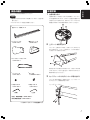
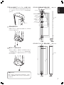
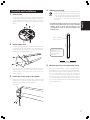
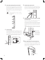
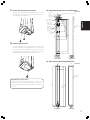
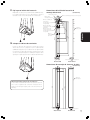
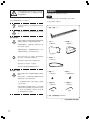
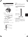
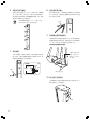
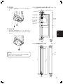
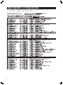
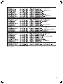
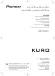
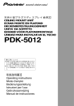
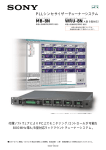
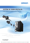
CP-VSL3
「据付工事」について
● 本機は十分な技術・技能を有する専門業者が
据付けを行うことを前提に販売されているも
のです。据付け・取付けは必ず工事専門業者
または販売店にご依頼ください。
● なお、据付け・取付けの不備、誤使用、改造、
天災などによる事故損傷については、弊社は
一切責任を負いません。
K042_Ja
このたびは、パイオニアの製品をお買い求めいただきまして
本製品はスピーカーシステムS-VSL3専用です。
まことにありがとうございます。お使いになる前にはこの据
付・取扱説明書をよくお読みになり、正しくお使いくださ
い。なお、「据付・取扱説明書」は「取付業者連絡票」と一
緒に必ず保管してください。
安全に正しくお使いいただくために
絵表示について
この取扱説明書および製品への表示は、製品を安全に正し
くお使いいただき、あなたや他の人々への危害や財産への
損害を未然に防止するために、いろいろな絵表示をしてい
ます。その表示と意味は次のようになっています。
指定外のスピーカーシステムの取り付けや改造お
禁止
注意
設置場所は金具とスピーカーシステムの重量に十
注意
損害のみの発生が想定される内容
を示しています。
絵表示の例
禁止
取り付けなどもしないでください。
禁止
人が容易にぶら下がったり寄り掛かれる場所には
設置しないでください。
% 記号は注意 (警告を含む) しなければならない内
容であることを示しています。
屋外や温泉、海辺の近くには設置しないでくださ
禁止
記号は禁止 (やってはいけないこと) を示してい
ます。
¶ 記号は行動を強制したり指示する内容を示してい
取扱上の注意
ご注意 安全上の絵表示について
禁止
ください。
注意
壁の構造強度により取り付けできない場合があり
ますので工事専門業者へご相談ください。
その他の設置場所についてはスピーカーシステム
注意
組み立ての手順を守り、指定の箇所はすべて確実
注意
注意
受けるおそれがある内容を示し
ます。
警告・注意(気をつけること)
禁止(やってはいけないこと)
指示・強制(しなければならないこと)
2
Ja
異常や不具合が発見されたならば速やかに修理を
注意
工事専門業者に依頼してください。
このスピーカー金具を長期間使用されると、環境
れがある内容を示します。
人がけがをしたり財産に損害を
にネジ止めしてください。
指定を守らないとスピーカーシステム取り付け後
に、破損や落下など思わぬ事故の原因となること
があります。
それら絵表示の意味は以下の通りです。
警告
S-VSL3 本体の取扱説明書を熟読し、その内容を
必ず守ってください。
組み立て・設置について
取扱説明書および製品に記されている注意事項には、
損害のレ
ベルや内容を示す絵表示が付けられていることがあります。
人が死亡または重傷を負うおそ
い。
振動や衝撃の加わるような場所には設置しないで
ます。
本機を壁に取り付けるためのネジは付属
していません。柱や壁の強度や材質に合
わせた適切なものを使用してください。
分耐えうる強度をもつ傾斜のない壁面を選定して
ください。
本製品をななめ、横向き、逆さなどの直立方向以
外の取り付け方をしないでください。天井面への
この表示を無視して、誤った取り
扱いをすると、人が損害を負う可
能性が想定される内容および物的
取り付けなどに不具合があると落下などの事故に
つながり大変危険です。
設置場所について
内容をよく理解してから本文をお読みください。
注意
よび他の用途への使用はしないでください。
注意
によっては経年変化で強度が不足することがあり
ます。5 年を目安として、工事専門業者に点検を
依頼し、使用して問題のないことをお確かめくだ
さい。
部品の確認
設置手順
組み立ての前に部品を確認してください。
1
日
本
語
台座を取り外す
ご注意
付属の六角レンチを使ってネジを3本取り、スピーカー
÷ 壁に取り付けるためのネジは付属していません。別途ご用
意ください。
から台座を取り外します。このネジと台座は元通りに付
け直すことができますので、将来スピーカーシステムを
床置きでお使いになる場合は保存しておいてください。
÷ プラスドライバーを別途ご用意ください。
÷ 壁プレート(本体) X 2
÷ 上プレート X 2
< SNA1422 >
÷ 端子カバ− X 2
< SNN1020 >
2
上プレートを取り付ける
スピーカー上部のネジ4本を、六角レンチ (3mm) を
使って取ります。上プレートを被せて、このネジを使っ
て六角レンチで取り付けます。
÷ セーフティーベルト X 2
< SEW1031 >
取り付けネジの六角穴がやや浅いので、六角レンチが滑
らないようにしっかりと差し込み、ゆるみがでないよう
÷ ブッシュ X 4
< SEP1303 >
確実に取り付けてください。
÷ ネジ X 6
< PMM60P120S >
3
セーフティーベルトをスピーカーに取り付ける
スピーカー裏の金具を一旦取りはずし、セーフティーベ
ルトをセットして再度取り付けます。
÷ 六角レンチ 5
< SEX1024 >
÷ 六角レンチ 3
< SEX1023 >
(台座)
セーフティーベルト
(上部)
÷ 据付・取扱説明書 < SRD1265 >
÷ 取付業者連絡票 < BZR1069 >
<>内はサービスパーツの部品番号です。
3
Ja
4
7
仮止めをする
本製品とスピーカーシステムS-VSL3を組み合わ
せると、約 10kg の質量になります。工事業者様
ブッシュ2個を取り付けます。ブッシュのフランジ部分
は金具から浮いた形で取り付けられ、万が一金具が壁か
指示 が壁の構造・材質により判断して、最適な手段で
止めてください。
●
ブッシュを取り付ける
ら脱落してしまう際に、急激な落下を防止する役割をし
ます。アンカーなどを使用して、十分な取り付け強度を
確保してください。
床からの高さを確認してください。端子カバーを取り
付けるため、プラスドライバーを床面と本体の間に入
れてネジ締め作業ができるだけの空間が必要です。
<断面図>
76.6
70
ブッシュ
仮止め用の穴
(ø5.5)
金具
ネジ
962.6
1055.6
ブッシュ
壁
8
セーフティーベルトを壁に取り付ける
セーフティーベルトを壁に取り付けます。アンカーなど
を使用して、十分な取り付け強度を確保してください。
スピーカーを取り付け
た後の外観寸法は、P.5
の寸法図を参考にして
ください。
セーフティーベルトもスピーカーシステム脱落防止のた
めの安全機構ですので必ず取り付けてください。
85
床
5
セーフティーベルト
取り付けネジの位置に印を付ける
水準器などを使用して垂直を確認し、壁の金具取り付け
ネジの位置に印を付けます。金具本体の取り付けネジ径
は 4 ∼ 5mm(推奨 5mm)6 ∼ 8ヶ所、セーフティー
ベルトの取り付け位置とネジ径は上部四角穴内に 5 ∼
6mm(推奨 6mm)1ヶ所、ブッシュの取り付け位置と
ネジ径は9×15の長穴内に5∼6mm(推奨6mm)2ヶ
所です。
6
壁に金具を取り付ける
金具の壁への取り付けは、上下両端
の4ヶ所(右図✱印)を含んで必ず6か
9
コードを取り付け金具に通す
コードを取り付け金具底面の四角形の穴に通します。金
具の背面に壁の内側からコードを出したい場合は、背面
のφ30の丸い穴 (3つ) のいずれかを通して底面の小さ
な穴を使用してください。
●
スピーカーの背面からコードを出す場合
所以上で止めてください。取り付け
金具を壁に取り付けるためのネジは
付属していません。壁の構造・材質
に応じてアンカー* 1 などを使用し
壁の内側からコー
て、十分な取り付け強度* 2 を確保し
てください。
ドを引き出す場合
は3 ヶ所のφ3 0
*1 アンカーは強度が0 . 3 k N
(ニュートン) 以上のものを
穴のうちのどれか
ひとつを使ってく
指示
ださい。
お使いください。
*2 安全率4 倍以上の強度で取
り付けてください。
どちらでも可
4
Ja
CP-VSL3 金具本体穴位置寸法図
φ
3-
日
本
語
32.5
60
(金具と壁の取り付け穴)
50x25 四角穴
(セーフティーベルト
取り付け穴)
3-φ30 穴
(スピーカーコード
引き出し穴)
320
443
520
仮止め用の穴
70
50
76.6
ら、上部のスリットにアッパープレートの突起部を差し
込みます。
5穴
5.
スピーカー端子を取り付け金具底面の角穴に通しなが
単位 (=mm)
43
105
145
10 取り付け金具にアッパープレートを差し込む
40
8-5.5x9 長穴
(金具と壁の
取り付け穴)
(壁面)
2-9x15 長穴
(ブッシュ取り付け穴)
962.6
843
900
スリット
11 底面の固定をする
底面3ヶ所のうち、図の2ヶ所を付属のネジ (PMM60
(16.4)
P120S) で固定します。
110
85
前
(正面)
後
(側面)
CP-VSL3 スピーカー取付寸法図
単位 (=mm)
133
(80)
107
12 端子カバーを取り付ける
端子カバーを被せて、付属のネジ (PMM60P120S) で
1ヶ所を固定します。スピーカーコードを壁内部に通さ
ない場合は端子カバー後部の切り欠きからコードを引き
(壁面)
1072
(992)
1041
出してください。
再度、床に置いて使用する可能性がある場合は、台座を
ネジと一緒に保管しておいてください。付けなおすこと
ができます。
31
台座について
前
(正面)
後
(側面)
5
Ja
This unit is not provided with screws
necessary for wall mounting. Please
provide the appropriate screws based on
the material and strength of the wall
where the unit is to be mounted.
This unit is designed for exclusive use with Pioneer Speaker
System S-VSL3.
Do not use with any speaker system other than
the one for which the unit was designed. Do not
PROHIBITED attempt to modify the structure or use for other
than the unit's designed purposes.
CAUTION
Confirm Parts
Please confirm that all parts are present before assembling.
Note
• Screws required for wall installations are not furnished and
must be provided by the user.
• A Phillips screwdriver is required for assembly.
• Wall plates (body) x2
Improper or unsafe mounting may allow
speakers to fall, leading to dangerous accidents.
Installation Location
The location selected for mounting should be
flat, and strong enough to fully able to support
CAUTION the weight of fixture and speaker.
Depending on the kind of wall construction,
some types of walls may not be strong enough to
safely support the unit and speaker; consult a
professional installation technician for advice.
• Upper plates x2
<SNA1422>
• Terminal cover x2
<SNN1020>
When using other kinds of installation, be sure to
read the speaker system S-VSL3's Operating
Instructions fully and abide by all instructions there.
Never install the unit at a slanting angle,
horizontally, or upside down. Also, never attach
PROHIBITED the unit to a ceiling.
• Safety strap x2
<SEW1031>
Do not install in locations where people may
easily hang from or lean against the unit.
Do not install outdoors, in hot spring baths, or in
locations near the ocean.
Do not install in locations where the unit may be
exposed to vibration or impact.
• Bushings x4
<SEP1303>
• Screws x6
<PMM60P120S>
Assembly and Installation
Follow the designated assembly steps properly,
and fasten the assembly screws securely in the
CAUTION designated locations. Failure to follow these
assembly instructions correctly may cause
damage to the unit or lead to dangerous
accidents after installation.
• Allen (hex)
wrench #5
• Allen (hex)
wrench #3
<SEX1024>
<SEX1023>
If you discover any abnormalities or irregularities
during assembly or installation, contact your
professional installation technician for repairs
as soon as possible.
(for base)
Due to varying environmental conditions, this
fixture may be subject to aging and lose adequate
supporting strength after an extended period of
usage. We highly recommend that each five years
of use (on average), you consult your professional
installation technician and have the fixture
inspected to assure continuing safety.
6
En
(for upper part)
• Installation and Usage Instructions <SRD1265>
Numbers in angle brackets <> are parts serial numbers.
1
4
Remove base
Temporary mounting
NOTE
Using the provided Allen wrench, remove the three base
screws and then the base from the speaker. Save these
screws and the base if there is any chance you will want to
replace the bases for ordinary floor installations in the
future.
When the mounting fixture is combined with the
speaker system S-VSL3, the total weight is about
10 kg. The installation technician should decide
on the optimum mounting method based on an
assessment of the wall’s materials and
structure.
• Confirm the height from the floor. Enough space
must be left between the floor surface and the
speaker body to allow the introduction of a
screwdriver in order to install and tighten the
terminal cover.
English
Assembly and Installation
76.6
70
Attach upper plate
962.6
2
1055.6
Hole for temporary
mounting (φ 5.5)
Using the furnished 3 mm Allen wrench, remove the four
screws from the top of the speaker. Place the upper plate
on the speaker top and use the 3 mm Allen wrench to
tighten the removed mounting screws.
Consult the dimensional
diagram on P. 9 for
external dimensions
following speaker
installation.
85
Floor
5
Since the hex holes in the mounting screws are rather
shallow, be sure to hold the Allen wrench securely to
prevent slipping, and tighten the screws securely to
prevent slipping.
3
Fasten the safety strap to the speaker
Temporarily remove the mounting fixture on the rear of the
speaker, place around the safety strap and once again
fasten the mounting fixture to the speaker.
Mark the position of the mounting screws
Use a level or plumb bob to confirm the perpendicular,
and mark the position of the mounting screws on the wall.
The mounting screws should have a diameter of 4-5 mm (5
mm is recommended) in 6-8 locations. The safety strap
location and mounting screw diameters should be 1
screw of 5-6 mm in the upper square hole (6 mm is
recommended); bushing location and screw diameters
are 2 screws of 5-6 mm (6 mm recommended) within the
9x15 rectangular hole.
Safety strap
7
En
6
Fasten the mounting fixture to the wall
8
When fastening the fixture to the wall, use a minimum of
six screw locations, including the four holes at the top and
bottom of the fixture (✱ marks). Mounting screws are not
furnished. Depending on the construction of the wall,
drywall anchors* 1 or other reinforcements may be
necessary; be sure to provide fully sufficient*2 support for
the speaker.
Attach safety strap to wall
Attach the safety strap to the wall. Using anchor bolts or
other means as necessary, provide ample support strength.
The strap is an important safety device to prevent the
speaker from falling, and should be installed in all cases.
Safety strap
*1 Anchors should have minimum strength of
0.3kN (Newtons).
NOTE *2 A safety factor of x4 or more should be
provided.
9
Connect speaker cords and pass through
mounting fixture
Connect the speaker cords and pass them through the
square hole on the bottom of the mounting fixture.
If you wish to pass speaker cords through the rear of the
mounting fixture, use either of the two holes on the bottom
of the fixture, then pass the cord through any of the three
round holes (φ 30) on the rear surface of the fixture, as
shown.
• When threading speaker cords from rear of speaker
7
Install bushings
When accessing
speaker cords the
rear of the speakers,
use one of the three
round holes (φ 30) in
the rear surface of
the mounting fixture.
Install two bushings per speaker. The bushing is installed
so that the bushing's flange is separated slightly from the
fixture's surface; this helps prevent the speaker from
falling suddenly in the event the fixture should
accidentally become detached from the wall. Use drywall
anchors or other means to provide ample strength.
<Cross section>
Wall
Bushing
Bushing
Mounting
fixture
Screw
Use either of these
10 Insert upper plate into mounting fixture
While passing the speaker’s terminals through the square
hole in the fixture’s bottom, set the speaker onto the
fixture, then place the upper plate onto the top of the
speaker as you insert the upper plate’s tab into the
opening on the top of the fixture.
Opening
8
En
(unit=mm)
3-φ5.5 holes
70
50
Mounting holes for fixture to wall
3-φ30 holes
(for passing
speaker cord)
8-5.5x9 long
holes (mounting
holes for fixture
to wall)
2-9x15
rectangular
holes
320
443
520
50x25 square
hole (for attaching
safety strap)
Wall
surface
962.6
843
900
40
English
32.5
60
Hole for
temporary
mounting
43
105
145
Using the two provided screws (PMM60P120S), secure
the bottom of the fixture to the speaker through the two
holes shown in the illustration.
CP-VSL3 Mounting Fixture Hole Dimensions
76.6
11 Secure the bottom of the fixture
12 Attach terminal cover
(16.4)
Place the terminal cover over the bottom of the fixture and
use the furnished screw (PMM60P120S) to secure the
cover in place. When the speaker cords are not passed
through the back of the fixture into a wall, pass the cords
through the gap at the back of the terminal cover.
110
85
Front
Front view
Back
Side view
CP-VSL3 Speaker Mounting Dimensions
133
(unit=mm)
(80)
107
1072
(992)
31
Regarding the speaker bases
If there is any chance you might want to install the
speakers on the floor again in future, be sure to preserve
the speaker bases safely together with their mounting
screws.
1041
Wall
surface
Front
Front view
Back
Side view
9
En
Esta unidad no está provista de los tornillos
necesarios para el montaje en la pared.
Adquiera los tornillos apropiados de
acuerdo con el material y la resistencia de la
pared donde se proponga montar la unidad.
Esta unidad está diseñada exclusivamente para su empleo con el
sistema de altavoces S-VSL3 Pioneer.
No la emplee con ningún otro sistema de
altavoces que no sea para el que ha sido diseñada
la unidad. No intente modificar la estructura no
PROHIBIDO
emplearla para otro propósito que no sea para lo
que está diseñada esta unidad.
Confirmación de las partes
Confirme que no falte ninguna parte antes del montaje.
Nota
• Los tornillos necesarios para las instalaciones en la pared
no se suministran y deberá adquirirlos el usuario.
• Se requiere un destornillador de cabeza en cruz para
realizar el montaje.
• Placas para la pared (cuerpo) x 2
El montaje inadecuado o inseguro puede hacer
que se caigan los altavoces, pudiendo ocasionar
PRECAUCIÓN graves accidentes.
Posición de instalación
La posición seleccionada para el montaje deberá
ser plana, o lo suficientemente resistente como
para poder soportar el peso de los accesorios y del
PRECAUCIÓN
altavoz.
• Placas supriores x 2
• Cubierta de terminales x 2
<SNA1422>
<SNN1020>
Dependiendo del tipo de construcción de la
pared, es posible que algunos tipos de paredes no
tengan una resistencia suficiente como para
poder soportar con seguridad la unidad y el
altavoz; pida consejo a un técnico profesional de
instalaciones.
Cuando emplee otros tipos de instalación,
asegúrese de leer el manual de instrucciones del
sistema de altavoces S-VSL3 y de seguir todas las
instrucciones dadas.
No instale nunca la unidad en un ángulo inclinado, horizontalmente, ni al revés. No fije
PROHIBIDO tampoco nunca la unidad al techo.
No la instale en lugares en los que la gente pueda
colgarse o apoyarse con facilidad en la unidad.
No la instale al aire libre, en baños termales, ni en
lugares cercanos al mar.
No la instale en lugares en los que la unidad
pueda quedar expuesta a vibraciones o golpes.
• Correa de seguridad x 2
<SEW1031>
• Bujes x 4
<SEP1303>
• Tornillos x 6
<PMM60P120S>
Montaje e instalación
Siga correctamente los pasos de montaje
designados, y fije los tornillos de montaje con
seguridad en las posiciones designadas. Si no
PRECAUCIÓN sigue correctamente las instrucciones de montaje,
correrá el riesgo de daños en la unidad o de
peligrosos accidentes después de la instalación.
Si descubre alguna anormalidad o irregularidad
durante el montaje o la instalación, póngase en
contacto con el técnico profesional de instalaciones para que efectúe las reparaciones lo antes
que sea posible.
Debido a los cambios de las condiciones
ambientales, este accesorio puede hacerse viejo y
perder la resistencia de soporte adecuada
después de mucho tiempo de utilización. Le
recomendamos encarecidamente que consulte a
un técnico profesional de instalaciones cada
cinco años (de promedio) para que inspeccione la
unidad y certifique su seguridad.
10
Sp
• Llave hexagonal
N.° 5
<SEX1024>
(para la base)
• Llave hexagonal
N.° 3
<SEX1023>
(para la parte superior)
• Manual de instalación y de utilización <SRD1265>
Los números entre corchetes angulares son los números
de serie de las partes.
Montaje e instalación
1
4
Extraiga la base
Montaje provisional
NOTA
Empleando la llave hexagonal suministrada, extraiga los
tres tornillos de la base y luego la base del altavoz. Guarde
estos tornillos y la base por si en el futuro decide realizar
una instalación normal en el piso.
Cuando se combina el accesorio de montaje con
el sistema de altavoces S-VSL3, el peso total es
aproximadamente de 10 kg. El técnico de
instalaciones deberá decidir el método óptimo de
montaje basándose en el material y la estructura
de la pared.
• Confirme la altura desde el suelo. Deberá dejarse
espacio suficiente entre la superficie del suelo y el
cuerpo del altavoz para poder introducir un
destornillador para poder instalar y apretar la
cubierta de terminales.
76.6
Español
70
Coloque la placa superior
962.6
2
1055.6
Orificio para montaje
provisional (φ 5,5)
Empleando la llave hexagonal de 3 mm suministrada,
extraiga los cuatro tornillos de la parte superior del
altavoz. Ponga la placa superior sobre la parte superior
del altavoz y emplee la llave hexagonal de 3 mm para
apretar los tornillos de montaje extraídos.
Consulte el diagrama de
dimensiones de la P. 13
para ver las dimensiones
externas después de la
instalación de los altavoces.
85
Piso
5
Puesto que los orificios hexagonales de los tornillos de
montaje son poco profundos, asegúrese de sostener la
llave hexagonal con seguridad para evitar que resbale, y
apriete los tornillos con seguridad para evitar
resbalamiento.
3
Fije con seguridad la correa al altavoz
Extraiga provisionalmente el accesorio de montaje de la
parte trasera del altavoz, ponga la correa de seguridad en
torno al altavoz y vuelva a fijar el accesorio de montaje al
altavoz.
Marque la posición de los tornillos de
montaje
Emplee un nivel o una plomada para confirmar la
perpendicularidad, y marque en la pared la posición de
los tornillos de montaje. Los tornillos de montaje deberán
tener un diámetro de 4-5 mm (se recomiendan 5 mm) en
6-8 lugares. Los diámetros de la posición de la correa de
seguridad y de los tornillos de montaje deberán ser de 5-6
mm (se recomiendan 6 mm) para el tornillo a usarse en el
orificio cuadrado superior; los diámetros de la posición de
los bujes y de los tornillos son de 5-6 mm (se recomiendan
6 mm) para los 2 tornillos a usarse dentro del orificio
rectangular de 9 x 15.
Correa de seguridad
11
Sp
6
Fije el accesorio de montaje a la pared
Cuando fije el accesorio a la pared,
emplee un mínimo de seis posiciones de
tornillo, incluyendo los cuatro orificios de
la parte superior e inferior del accesorios
(marcas ✱). Los tornillos de montaje no
se suministran. Dependiendo de la
construcción de la pared, puede resultar
necesario emplear tacos para muro de
piedra en seco * 1 u otros refuerzos;
asegúrese de proporcionar un soporte
suficiente *2 para el altavoz.
9
Conecte los cables de altavoz y páselos por
el accesorio de montaje
Conecte los cables de altavoz y páselos por el orificio
cuadrado de la parte inferior del accesorio de montaje.
Si desea pasar los cables de altavoz la parte posterior del
accesorio de montaje, pase el cable a través de uno de los
dos orificios de la parte inferior del accesorio y páselo por
cualquiera de los tres orificios redondos (φ 30) de la
superficie posterior del accesorio.
• Cuando se pasan los cables de altavoz desde la
parte posterior del altavoz.
*1 Los tacos para muro de piedra
en seco deberán tener una
NOTA
resistencia mínima de 0,3 kN
(Newton).
*2 Deberá proporcionarse un
factor de seguridad de 4 o
más veces.
7
Para acceder a los
cables de altavoz
desde la parte
posterior del altavoz,
emplee los tres
orificios redondos
(φ 30) de la superficie
posterior del accesorio
de montaje.
Instale los bujes
Instale dos bujes por altavoz. El buje se instala de modo
que la brida del buje quede un poco separada de la
superficie del accesorio; de este modo se ayuda a evitar
que el altavoz pueda caerse súbitamente en el caso de
separarse accidentalmente el accesorio de la pared.
Emplee tacos para muro de piedra en seco u otros medios
para proporcionar mayor resistencia.
Emplee uno de éstos
10 Inserte la placa superior en el accesorio de
montaje
<Sección transversal>
Pared
Buje
Buje
8
Accesorio
de montaje
Tornillo
Fije la correa de seguridad a la pared
Fije la correa de seguridad a la pared. Empleando pernos de
anclaje u otros medios, como sea necesario, proporcione
mucha resistencia de soporte. La correa es un dispositivo
de seguridad importante que evita que se caigan los
altavoces, y deberá instalarse sin falta.
Correa de seguridad
12
Sp
Mientras pasa los terminales de altavoz por el orificio
cuadrado de la parte inferior del accesorio de montaje,
coloque el altavoz en el accesorio de montaje, y luego
ponga la placa superior encima del altavoz mientras
inserta la lengüeta de la placa superior en la abertura de
la parte superior del accesorio de montaje.
Abertura
Orificios de 3- φ5,5
70
50
Orificio para
montaje provisional
40
Orificios largos de
8-5,5x9 (orificios de
montaje para fijación
en la pared)
962.6
843
900
Orificios
rectangulares
de 2-9x15
Superficie
de la pared
Español
Orificios de 3-φ30
(para pasar el cable
de altavoz)
320
443
520
43
105
145
Orificio cuadrado de
50x25 (para
montaje de la correa
de seguridad)
Orificios de montaje para fijación en la pared
32.5
60
Empleando los dos tornillos suministrados (PMM60P120S),
fije la parte inferior del accesorio de montaje al altavoz a
través de los dos orificios mostrados en la ilustración.
Dimensiones del orificio del accesorio de
montaje del CP-VSL3
(unidad=mm)
76.6
11 Fije la parte inferior del accesorio
12 Coloque la cubierta de terminales
(16.4)
Ponga la cubierta de terminales encima de la parte
inferior del accesorio y emplee el tornillo suministrado
(PMM60P120S) para fijar la cubierta en su lugar. Cando
no se pasan los cables de altavoz por la parte posterior del
accesorio a una pared, pase los cables por el espacio libre
que hay en la parte posterior de la cubierta de terminales.
110
85
Parte frontal
Vista frontal
Parte posterior
Vista lateral
Dimensiones de montaje de altavoces CP-VSL3
133
(unidad=mm)
(80)
107
1072
(992)
31
Observación sobre las bases de los altavoces
Si en el futuro usted decide instalar los altavoces otra vez
en el suelo, asegúrese de conservar las bases de los
altavoces en un lugar seguro junto con sus tornillos de
montaje.
1041
Superficie
de la pared
Parte frontal
Vista frontal
Parte posterior
Vista lateral
13
Sp
本機沒有配備將本機安裝在牆壁上使用的螺
絲。請選擇並使用符合柱子或牆壁強度或材質
的適當的螺絲。
確認部件
在進行裝配之前,確認各部件是否齊全。
注意
本產品為揚聲器系統S-VSL3型專用。
禁止
請勿使用於安裝指定之外的揚聲器系統或改造及
其他用途。
注意
如果安裝不妥當,可能會導致危險的落下等事
故。
÷ 沒有配備安裝在牆上時使用的螺絲,請另外準備。
÷ 需另外準備十字螺絲刀。
÷ 壁板(主體)× 2
關於設置場所
設置場所應選定具備能耐安裝配件和揚聲器系統
重量的足夠強度的,沒有傾斜的牆壁表面。
注意
÷ 上板× 2
÷ 端子罩× 2
< SNA1422 >
< SNN1020 >
依牆壁結構強度,可能會有無法安裝的情況,請
與工程專業人員恰商。
有關其他設置場所,請細讀揚聲器系統S-VSL3型
主體的操作說明書,並必須遵守其內容。
請勿以垂直以外的方向,如傾斜、橫向或倒過來
禁止
進行安裝。亦請勿安裝在頂棚表面上。
÷ 安全帶× 2
< SEW1031 >
請勿設置在人能夠容易搭拉或倚靠的場所。
請勿設置在室外或溫泉、海濱附近。
請勿設置在會有振動或衝擊施加的場所。
關於裝配、設置
應遵守裝配的步驟,使用螺絲確實緊固全部指定
部位。
注意
÷ 襯套× 4
÷ 螺絲× 6
< SEP1303 >
< PMM60P120S >
如果忽略指定,可能會成為造成揚聲器系統安裝
後破損或落下等意外事故的原因。
萬一發現到異常或故障,務請立即委託工程專業
人員進行修理。
÷ 六角扳手 5
÷ 六角扳手 3
< SEX1024 >
< SEX1023 >
(基座)
(上部)
如果長時間使用本揚聲器安裝配件,依使用環境
可能會有因長年時效變化而造成強度不足的情
況。請以5 年為基準委託工程專業人員進行檢
查,確認對使用不存在問題。
÷ 安裝•使用說明書< SRD1265 >
<
14
ChH
>內為維修零件的零件號碼。
安裝步驟
1
4
臨時固定
拆卸基座
指示
使用附屬的六角扳手來取下3個螺絲,從揚聲器拆卸基座。
此螺絲和基座可以原樣重新安裝,因此打算將來在地板上
安放揚聲器使用時,需將它們保管好。
¶
組合本產品和揚聲器系統S-VSL3型時,重量將達
到約10kg。需由工程人員根據牆壁的結構、材質
予以判斷,以最合適的方法固定下來。
確認從地板的高度。由於需要安裝端子罩,需要有足夠
的空間,以便將十字螺絲刀插入地板面與主體之間進行
螺絲緊固作業。
76.6
70
962.6
1055.6
臨時固定用孔(φ 5.5)
2
安裝上板
關於揚聲器安裝結束
後的外觀尺寸,請參
考第 17 頁的尺寸圖。
用六角扳手(3mm)取下揚聲器上部的4個螺絲。蓋上上
板,用這些螺絲用六角扳手安裝。
中
文
85
樓板
5
在螺絲安裝位置做記號
用水平儀等確認垂直後,在牆壁上的安裝配件螺絲安裝位
置做好記號。整個安裝配件的安裝螺絲直徑為4∼5mm
因為安裝螺絲的六角孔淺一些,因此要充分插入,以免六
角扳手滑動,並確實安裝,確保不會造成鬆動。
3
將安全帶安裝在揚聲器上
(推薦5mm)共6∼8處,安全帶的螺絲直徑和安裝位置
為在上部方形孔內5∼6mm(推薦6mm)1處,襯套的
螺絲直徑和安裝位置為在9×15的長孔內5∼6mm
(推薦6mm)共2處。
暫時取下揚聲器背面的安裝配件,在安裝了安全帶後再次
安裝。
安全帶
15
ChH
6
8
將配件安裝在牆壁上
將安全帶安裝在牆上
將配件安裝在牆壁上時,包括上下兩端4處(下圖✱標
將安全帶安裝在牆上。使用錨定器等來確保充分的安裝強
記)必須在6處以上加以固定。本產品沒有供應將配件安
裝在牆壁上使用的螺絲。需根據牆壁的結構、材質,使用
度。安全帶也是一種為防止揚聲器掉落而使用的安全機
構,務必將它安裝好。
錨定器*1等確保充分的安裝強度*2。
*1 錨定器需使用強度在0.3kN(牛頓)以上的。
指示
安全帶
*2 需以安全率4倍以上的強度安裝。
9
安裝軟線並使其穿過配件
安裝軟線並使其穿過配件底面的方形孔。如果希望使軟線
從牆壁內側向配件背面穿過,使軟線穿過位於背面的圓形
孔(3個)中的任意一個並使用位於底面的小孔。
¶ 使軟線從揚聲器背面穿過時
7
安裝襯套
從牆壁內側引出軟
線時,使用位於 3
處的φ 30 孔中的任
意一個孔。
安裝2個襯套。襯套的凸緣部分安裝成從配件浮起的狀
態,起萬一在配件從牆壁脫落時防止急劇落下的作用。使
用錨定器等來確保充分的安裝強度。
<斷面圖>
牆壁
襯套
襯套
安裝配件
螺絲
可使用任意一個
10
將上板插入安裝配件
在使揚聲器端子穿通安裝配件底面的矩形孔的同時,將上
板的凸起部插入上部切縫中。
切縫
16
ChH
11
固定底面
底面3處中,用配備的螺絲(PMM60P120S)固定下圖所示2
CP-VSL3 型安裝配件主體孔位置尺寸圖
3-φ 5.5 孔
70
50
處。
單位(= mm)
(安裝配件與牆壁的安裝孔)
50 × 25 方形孔
(安全帶安裝孔)
3-φ 30 孔(揚聲
器軟線引出孔)
320
443
520
43
105
145
32.5
60
76.6
臨時固定用孔
40
8-5.5 × 9 長孔
(安裝配件與牆
壁的安裝孔)
(牆壁
表面)
962.6
843
900
2-9 × 15 長孔
(襯套安裝孔)
12
安裝端子罩
蓋上端子罩,用配備的螺絲(PMM60P120S)固定1處。不
擬將揚聲器軟線穿通牆壁內部時,將軟線從端子罩後部的
中
切口引出。
(16.4)
文
110
85
前
(正面)
後
(側面)
CP-VSL3型揚聲器安裝尺寸圖
單位(=mm)
133
(80)
107
關於基座
(牆壁
表面)
1072
31
(992)
1041
如果有再次安放在地板上使用的可能性,將基座與螺絲一
起保管。這樣,可以重新安裝並使用。
前
(正面)
後
(側面)
17
ChH
修理のご相談/修理についてのお問い合わせ窓口
パイオニア製品についてのご購入相談はお近くの販売店へ、修理についてはお買い求めの販売店へご依頼ください。
万一お困りの場合は、窓口(裏表紙)へご相談くださるようお願いいたします。
18
Ja
19
Ja
修理窓口・ご相談窓口のご案内
ご購入後の製品の修理・お取り扱いのご相談は、お買い求めの販売店へお問い合わせください。
<ご注意>市外局番「0070」で始まる フリーフォン及び「0120」で始まる フリーダイヤルはPHS、携帯電話などからはご使用になれません。
また、【一般電話】は、携帯電話・PHSなどからご利用可能ですが、通話料がかかります。
製品のご購入や取り扱いについてのご相談窓口
● カスタマーサポートセンター (全国共通フリーフォン)
受付 月曜∼金曜 9:30 ∼ 17 :00、 土曜・日曜・祝日 9:30 ∼ 12:00 、13:00 ∼ 17:00 (弊社休業日は除く)
家庭用オーディオ/ビジュアル製品
(PDP・DVDなど)のご相談窓口
:
:【一般電話】
カタログのご請求窓口
:
ファックス受付
:
パイオニアホームページでのご案内
お問い合わせ先のご案内
カタログ請求とメールサービス登録のご案内
http://www.pioneer.co.jp/support/faq/index.html
http://www.pioneer.co.jp/support/ctlg/index.html
部品のご購入についてのご相談窓口
部品(付属品、リモコン、
・
取扱説明書など)のご購入については、部品受注センターへお問い合わせください。
● 部品受注センター
弊社休業日は除く)
受付 月曜∼金曜 9:30 ∼ 18 :00、 土曜・日曜・祝日 9:30 ∼ 12:00 、13:00 ∼ 17:00 (
電話(フリーダイアル)
:
一般電話
:
ファックス(フリーダイアル):
0120-5-81095
0538-43-1161
0120-5-81096
修理のご依頼/修理についてのご相談窓口
修理を依頼される前に取扱説明書の「故障かな?と思ったら」の項目をご確認ください。それでも正常に動作しない場合は、必ず
電源プラグを抜いてから、「保証とアフターサービス」をお読みになり、お買い求めの販売店へご連絡ください。
お買い求めの販売店に修理の依頼が出来ない場合は、修理受付センターへ。
(沖縄県の方は、沖縄サービスステーションへ)
● 修理受付センター(沖縄県を除く全国)
弊社休業日は除く)
受付 月曜∼金曜 9:30 ∼ 20 :00、 土曜・日曜・祝日 9:30 ∼ 12:00 、13:00 ∼ 18:00 (
ゴー パ イ オ ニ ア
電話(フリーダイアル)
:
一般電話
:
ファックス(フリーダイアル):
0120-5-81028
03-5496-2023
0120-5-81029
● 沖縄サービスステーション(沖縄県のみ)
受付 月曜∼金曜 9:30 ∼ 18 :00 (土曜・日曜・祝日・弊社休業日は除く)
一般電話
ファックス
: 098-879-1910
: 098-879-1352
c 2004 パイオニア株式会社 禁無断転載
153-8654
東京都目黒区目黒1丁目4番1号
PIONEER CORPORATION
4-1, Meguro 1-Chome, Meguro-ku, Tokyo 153-8654, Japan
PIONEER ELECTRONICS (USA) INC.
P.O. BOX 1540, Long Beach, California 90810-1540, U.S.A. TEL: (800) 421-1404
PIONEER ELECTRONICS OF CANADA, INC.
300 Allstate Parkway, Markham, Ontario L3R OP2, Canada TEL: (905) 479-4411
PIONEER EUROPE NV
Haven 1087, Keetberglaan 1, B-9120 Melsele, Belgium TEL: 03/570.05.11
PIONEER ELECTRONICS ASIACENTRE PTE. LTD.
253 Alexandra Road, #04-01, Singapore 159936 TEL: 656-472-1111
PIONEER ELECTRONICS AUSTRALIA PTY. LTD.
178-184 Boundary Road, Braeside, Victoria 3195, Australia, TEL: (03) 9586-6300
PIONEER ELECTRONICS DE MEXICO S.A. DE C.V.
Blvd.Manuel Avila Camacho 138 10 piso Col.Lomas de Chapultepec, Mexico,D.F. 11000 TEL: 55-9178-4270
K002_En
Printed in Japan
<SRD1265-A>