1
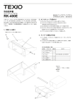
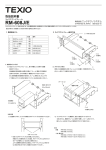
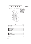
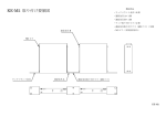
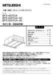
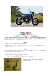
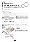
取扱説明書
ラック・マウント・アダプタ
OM-15E
© PRINTED IN JAPAN
B68-0017-00
1. 付属されている部品
記号
C
D
E
F
G
H
品名
ラックマウント金具
取付ネジ(サラネジ)
山形ワッシャ
丸皿ネジ
フレーム
皿ネジ
M4×16mm
M5×14mm
M3×8mm
数量
2個
4本
4個
4本
2個
4本
2. 取付け前の準備
左右のサイドカバーA (前側のみ 2 個)を取付けているネジ B 2 本(計 4 本)をゆるめてはずします。(図 1 参照)
3. ラックマウント金具の取付け
① ラックマウント金具 C (左右共通)の取付け穴(長穴ではない)に、準備の時にはずしたサイドカバーのネジ
穴 2 箇所を合わせ、取付けネジ(M4×16mm) D を使用して、セットに取付けます。(図 2 参照)
② フレームをセットの上下に皿ネジ(M3×8mm) H を使用してラックマウント金具に取付けます。
③ ラックマウント金具を装着したセットをラック本体に取付けるときは、付属の山形ワッシャ E、丸皿ネジ F を
使って、ラック本体にネジ止めします。(図 2 参照)
注意: ラック本体に取付けたあとは必ず、セット本体を下側からアングルサポート金具等で支えてください。
INSTRUCTION MANUAL
RACK MOUNT ADAPTER
OM-15E
© PRINTED IN JAPAN
B68-0017-00
1. CONTENTS
Symbol
C
D
E
F
G
H
Name
Rack mount adapter
Set screw (Countersunk head screw)
Angle washer
Oval countersunk head screw
Frame
Countersunk head screw
M4×16mm
M5×14mm
M3×8mm
Q’ty
2
4
4
4
2
4
2. PREPARATION
Remove each two screws B , which fix the side covers A in the front of the right and left side panels
(four screws in all). (See Fig.1 below)
3. ATTACHING RACK MOUNT ADAPTERS
① Fit the holes (not the slotted holes) in the rack mount adapter C to two threaded holes, from which the
screws have been removed in PREPARATION above. (The right and left rack mount adapters are
quite the same.) Attach the rack mount adapter to the equipment with two set screws D (M4×16mm).
(See Fig. 2 below)
② Fit the frames to the rack mount adapter on the top and bottom of the equipment with the
countersunk head screws H (M3×8mm).
③ Mount the equipment with the rack mount adapters to the rack with the angle washers E and oval
countersunk head screws F . (See Fig.2 below)
NOTE: Be sure to support the equipment with angle support brackets, etc. from beneath after
mounting the equipment to the rack.