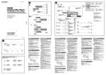
1
Model No.
TY-PG70LF50
TY-PG80LF50
施工説明書
Instructions d’installation
保護ガラス
Vitre de protection
⫭堩㔡ⵉ存㕲᷊
Instrucciones de montaje
ὁ㈈䌟䏧
Cristal Protector
Fitting Instructions
Protective Glass
Montageanweisungen
Schutzglas
Istruzioni di montaggio
!" # $
Vetro di protezione
%
TQZJ479
2
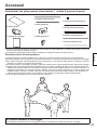
• Lisez le manuel d’installation avec attention de façon à ce que les opérations de montage du produit se déroulent
correctement et en toute sécurité. Lisez les “Précautions de sécurité” notamment avant de monter le produit. Conservez le
manuel d’installation dans un lieu sûr avec le mode d’emploi de l’écran.
• Nous ne pourrons être retenus responsables en cas d’accident ou de dommage se produisant suite à un montage de
l’applique ne correspondant pas aux instructions du manuel d’installation ou sans l’utilisation des pièces indiquées.
• Lea atentamente las instrucciones de instalación para poder instalar el producto en su lugar de forma correcta y
segura. Asegúrese de leer las “Precauciones para su seguridad”, en especial antes de instalar el producto. Guarde
bien las instrucciones de instalación, junto con las instrucciones de funcionamiento de la pantalla.
• No nos haremos responsables de los accidentes o daños que se puedan producir al instalar el producto de una
forma distinta de la que se indica en las Instrucciones de instalación o sin utilizar las piezas especicadas.
• , ! "# . $, “% ”. & "# "# '# .
• % ! ! , ! $ -
, ! , $ "# , .
• ()) * + /))
01) 5)$) */ */ /6
. ()) “8// 1” 5)) )) 0 / 1:6
. ; 5)$) */
) 5)$) */ )$ /6
.
• ; 5)$) */ + 5)) / : 5)$ 51)
/ : :, $ +)
+) + /: )
.
• < ! ! #) =#) . >, ! “>)) ”. >)$ =#) =#) #) ) )#).
• % ))) ) 1, )) ) $ - , )) ) , $ =#) , .
日本語
ᶑ㓫
English
Deutsch
Italiano
Français
• Leggere attentamente le Istruzioni di montaggio in modo da installare il prodotto in posizione in maniera corretta e
sicura. Leggere in particolare le “Precauzioni di sicurezza” prima di montare il prodotto. Conservare le Istruzioni di
montaggio in un luogo sicuro, insieme alle istruzioni d’uso dello schermo.
• Si declina qualsiasi responsabilità per incidenti o danni occorsi durante il montaggio del prodotto secondo modalità
diverse da quelle indicate nelle Istruzioni di montaggio o nel caso in cui non siano utilizzate le parti specicate.
Español
• Lesen Sie die Montageanleitung bitte sorgfältig durch, sodass das Produkt ordnungsgemäß und sicher angebracht
wird. Lesen Sie insbesondere die „Sicherheitsmaßnahmen“, bevor Sie das Produkt anbringen. Bewahren Sie die
Montageanleitung zusammen mit der Bedienungsanleitung für das Display an einem sicheren Ort auf.
• Wir übernehmen keine Haftung für Unfälle oder Schäden, die durch die Anbringung des Produkts auf andere Weise
anders als in der Montageanleitung angegeben oder ohne Verwendung der vorgeschriebenen Teile entstehen.
• Read the Fitting Instructions carefully so that the product can be properly and safely installed
in place. Make sure to read “Safety precautions” in particular before tting the product. Keep
the Fitting Instructions in a safe place, together with the operating instructions for the display.
• We shall have no liability for any accidents or damage incurred by tting the product in any
manner other than as provided in the Fitting Instructions, or without using parts specied.
孛Ḹ个敩孟㔡ⵉ存㕲᷊ṉ䟒ὁ㫇䟒⫭⚔⭪㚐ḋ␥⫭堩↔ằɁ⚌弿垰㔡ⵉᶯ↱濇孛∅⼩敩孟ĥ⫭
㱌びᷯ柝ĦɁ孛⭪㔡ⵉ存㕲᷊ᵲ䘵太◌䗨㐱Ề存㕲᷊ᵤ峛⤉ⓨὁ䬅Ɂ
⭝ᷲ㚎㉭䃋㚐㔡ⵉ存㕲᷊ᶑḯ丱䗨㔝㰹ㅺ㚎ợ䒌㉫⫾䗨恌Ṛ⫭堩㚐ḋ␥ㆤ⭠兘䗨ṟẹᷯ㒩ㅺ㋃⚳濇
㚐⃐⍜⾹ᵱ㇣㈩ṟẹ岇ṟɁ
• 施工説明書をよくお読みのうえ、正しく安全に施工してください。特に 「安全上のご注意」 は、
施工前に必ずお読みください。機器本体の取扱説明書とともに大切に保管してください。
• 施工説明書に記載されていない方法や、指定の部品を使用しない方法で施工されたことによ
り事故や損害が生じたときには、当社では責任を負えません。
3
日本語
安全上のご注意
必ずお守りください
人への危害、財産の損害を防止するため、必ずお守りいただくことを説明しています。
■誤った使い方をしたときに生じる危害や損害の程度を区分して、説明しています。
警告
注意
「死亡や重傷を負うおそれがある内容」です。
「軽傷を負うことや、財産の損害が発生するおそれがある内容」です。
■お守りいただく内容を次の図記号で説明しています。(次は図記号の例です)
してはいけない内容です。
実行しなければならない内
容です。
気をつけていただく内容で
す。
警告
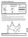
■ 工事専門業者以外は取り付け工事や
取り外しを行わないでください
工事の不備により、落下してけがの
原因となります。
注意
■ カタログで指定した機器以外には、
使用しないでください
落下したり、破損して、けがの原因
となることがあります。
■ 指定方法以外の取り付けは行わない
でください
落下したり、破損して、けがの原因
となることがあります。
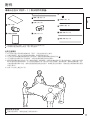
■ 機器本体の取り付け、取り外しは 4
人以上で行ってください
機器本体が落下して、けがの原因と
なることがあります。
■ 取り付けの際は、専用の構成部品を
ご使用ください
機器本体が落下したり、破損して、
けがの原因となることがあります。
■ 組み立て時、ねじ止めをする筒所は、
すべてしっかり止めてください
不十分な組み立てかたをすると強度
が保てず、落下したり、破損して、
けがの原因となることがあります。
■ 取り付け、取り外し作業時は同梱の
手袋を必ずお使いください
取り付け、取り外し時に手のけがの
原因となることがあります。
■ 取り付けの不備、取り扱い不備による事故、損傷については責任を負いません。
4
付属品が入っていることをご確認ください。
( )は個数です。
㇙ 保護ガラス (1 枚)
㇜ ゴム(厚・長) (2本)
㇠ ねじ (10 本)
日本語
付属品
㇝ ゴム(厚・短) (4本)
㇡ 不織布(長) (2本)
㇞ 金具(大) (8個)
㇚ 手袋 (4組)
㇛ 施工説明書
㇢ 不織布(短) (4本)
㇟ 金具(小) (2個)
㇣ ゴム(薄・長) (2本)
ゴム(薄・短) (4本)
■イラストはイメージイラストであり、実際の商品と形状が異なる場合があります。
■製品の仕様は予告なく変更する場合があります。
取り扱い上のお願い
1) 設置時、衝撃などによる保護ガラスの「割れ」が発生する場合がありますので、取り扱いにはご注意ください。
2) 保護ガラス、ディスプレイパネル、キャビネットに傷がつかないように作業をしてください。
3) 保護ガラスやディスプレイパネルに指紋がつかないよう、作業時は付属の手袋㇚を着用してください。
4) 製品や床に傷が付かないよう、柔らかい布やスポンジなどを使い作業してください。
5) 保護ガラスのお手入れは、柔らかい乾いた布(綿・ネル地)で軽くふいてください。
ひどい汚れや保護ガラスの表面に付着した指紋汚れなどは、水で 100 倍に薄めた中性洗剤に布をひたし、固く
絞ってふき取り、乾いた布で仕上げてください。なおベンジンやシンナー、家具用ワックスなどは使用しないで
ください。
(機器本体のお手入れは機器本体の説明書に従ってください。化学ぞうきんをご使用の際は、その注
意書に従ってください。
)
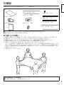
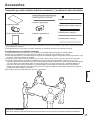
6) 作業は4人以上で行ってください。
施工業者様へのお願い
■ 工事終了後はお客様へこの説明書をお渡しください。
5
日本語
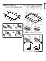
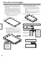
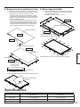
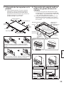
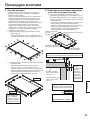
取り付け手順
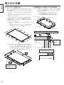
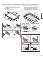
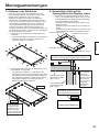
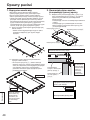
1. キャビネットを取り外す
2. 機器本体のベゼル面にゴム(厚)を貼る
安定した水平な場所に柔らかい布やスポンジなどを
敷き、機器本体をパネルが上向きになるように置い
てください。
ディスプレイパネルのほこりや汚れは取り除いて
ください。
ディスプレイパネルは柔らかい布(綿・ネル地など)
で軽くふいてください。
ひどい汚れやディスプレイパネルの表面に付着し
た指紋汚れなどは、水で 100 倍に薄めた中性洗
剤に布をひたし、固く絞ってふき取り、乾いた布
で仕上げてください。
1-1. キャビネット側面のねじ(20本)を外してく
ださい。
取り外したねじはキャビネットの取り付け時
に使用しますので大切に保管してください。
2-1. 付属のゴム(厚・長)㇜(2本)、ゴム(厚・短)
㇝(4本)を機器本体のベゼル面に下図の順で
貼ってください。
ゴムは伸ばさないように貼ってください。
ゴムはすき間がないように貼ってください。
ベゼル面の直角部に合わせて貼ります。
ゴム(厚・長)㇜
ゴム(厚・短)㇝
ヂ
ツ
ヅ
テ
ッ
ゴム(厚・短)㇝
デ
ゴム(厚・長)㇜
上下のゴムの左右位置は左右のゴムからはみ出さないこと。
左右のゴムの
上下位置はベゼ
ル開口からはみ
出さないこと。
上下のゴム(厚・短)㇝
1-2. キャビネットを下図の順で外してください。
キャビネット(下側)
(④)には、基板があ
ります。基板の配線に負担が掛からないよう
に注意しながら外してください。配線はつな
がったままで以後の作業を進めてください。
左右のゴム(厚・長)㇜
ベゼル開口に合わせて貼る。
ベゼル開口からはみ出さないこと。
①
上側
ゴム
③
ディスプレイパネル断面
④
下側
基板の配線に負担が
掛からないように注
意して外す。
6
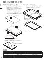
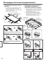
②
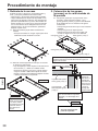
4. キャビネットに不織布とゴム(薄)を貼る
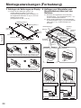
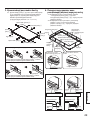
3-1. 金具(大)㇞(8個)、金具(小)㇟(2個)
を機器本体のキャビネット固定金具に付属のね
じ㇠(10本)で下図のように取り付けてくだ
さい。
(締め付けトルクは 0.9 ∼ 1.1 N・m)
4-1. キャビネットの内側側面に付属の不織布(長)
㇡(2本)、不織布(短)㇢(4本)を貼って
ください。
4-2. キャビネットの内側前面に付属のゴム(薄・長)
㇣(2 本)、ゴム(薄・短)(4 本)を貼っ
てください。
金具(大)㇞
金具(小)㇟
不織布 ( 長 ) ㇡
日本語
3. 機器本体に金具を取り付ける
不織布 ( 短 ) ㇢
キャビネット
金具(大)
㇞
ゴム ( 薄・長 )
㇣
ゴム ( 薄・短 )
キャビネット
(上側)
ゴム ( 薄・長 )
㇣
金具(大)
㇞
ねじ㇠
金具(小)㇟
金具(大)㇞
キャビネット
(下側)
不織布
(短)㇢
不織布 ( 長 ) ㇡
キャビネット
金具(大)㇞の取り付け方
キャビネット(下側)の
基板取付部
キャビネット(下側)の中央部
ねじ㇠
金具(大)㇞のフックを図のようにキャビネット固定金具に取り付ける。
金具(小)㇟の取り付け方
不織布
不織布
TY-PG70LF50
TY-PG80LF50
ねじ㇠
金具(小)㇟のフックを図のようにキャビネット固定金具に取り付ける。
ゴム
不織布
キャビネットからはみ出さない
ゴム
キャビネットからはみ出さない
不織布
不織布
ゴム
ゴム
貼り付け
基準
不織布
貼り付け
基準
貼り付け
基準
貼り付け
基準
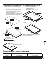
7
日本語
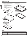
取り付け手順(つづき)
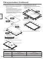
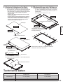
5. 保護ガラスを機器本体の上へ置く
6. キャビネットを取り付ける
5-1. 保護ガラス裏側の保護フィルムをはがし、機器
本体に貼り付けたゴムの上に置いてください。
作業は4人以上で行ってください。
保護ガラスをディスプレイパネルに当てない
よう注意してください。
保護ガラスが汚れていないか確認してください。
保護ガラスとディスプレイパネルとの間にほ
こりが入らないように注意してください。
保護ガラスはラベルがある面が裏側です。ラベル
が左下になるように機器本体に付けてください。
6-1. キャビネットを下図の順で取り付け、手順1で
外したねじ(20本)で固定してください。
(締め付けトルクは 0.9 ∼ 1.1 N・m )
④
上側
②
キャビネット位置
決め
保護ガラス
①
下側
表側
③
基板の配線をはさまないよ
うに注意してください。
※
裏側
※
保護フィルムをはがす
上側
保護ガラス㇙
※
※
ラベル(裏側)
※印の部分からねじを締める
下側
保護ガラスの外形を
ディスプレイパネル
外形に合わせる
保護ガラス
ゴム
ディスプレイパネル
5-2. 保護ガラス表側の保護フィルムをはがしてく
ださい。
保護フィルムをはがす
仕様
8
TY-PG70LF50
TY-PG80LF50
寸法
幅 1564 mm ×高さ 900 mm
×厚み 1.3 mm
幅 1819 mm ×高さ 1044 mm
×厚み 1.3 mm
質量
約 5 kg
約 6.5 kg
透過率
約 93 %
日本語
使いかた・お手入れ・修理などは、まず、お買い求め先へご相談ください。
その他ご不明な点は下記へご相談ください。
パナソニック システムお客様ご相談センター
受付: 9時∼17時30分
(土・日・祝祭日は受付のみ)
ホームページからのお問い合わせは https://sec.panasonic.biz/solution/info/
ご使用の回線(IP 電話やひかり電話など)によっては、回線の混雑時に数分で切れる場合があります。
【ご相談窓口におけるお客様の個人情報のお取り扱いについて】
パナソニック株式会社およびグループ関係会社は、お客様の個人情報をご相談対応や修理対応などに利用させて
いただき、ご相談内容は録音させていただきます。また、折り返し電話をさせていただくときのために発信番号
を通知いただいております。なお、個人情報を適切に管理し、修理業務等を委託する場合や正当な理由がある場
合を除き、第三者に開示・提供いたしません。
個人情報に関するお問い合わせは、ご相談いただきました窓口にご連絡ください。
〒 567-0026 大阪府茨木市松下町1番1号
© Panasonic Corporation 2012
9
⫭㱌びᷯ柝
嫊⎮
乁ᵱ偡䒕⫭堩ᵷᵾḞ⎼ᶯ⡺䗨Ḟ⡏弿垰⫭堩ⵉỀɁ
!!
ᵱ㫇䟒䗨⫭堩⍓偡Ṿợ嬢⡫㋭厡濇径ㅴẈ⬗Ɂ
ᶑ㓫
㱌び
孛≣ợ䒌䙒⺹ᶑ㌴⌮䗨䘵太◌ṉ⡺䗨ṟẹḋ␥Ɂ
!⎊ⅽ⍓偡Ṿ㋃⚳䘵太◌ㅺợ⃚㋭厡濇径ㅴḞặ⌻ẈɁ
孛ḩ㉭䃋存㕲᷊ᶑ䗨㉫⫾㫉樈⫭堩䘵太◌濕孛≣ṉ⃚⫧㔝㰹弿垰⫭堩Ɂ
!⎊ⅽ⍓偡Ṿ㋃⚳䘵太◌ㅺợ⃚㋭厡濇径ㅴḞặ⌻ẈɁ
∅⼩兗䒕!5!Ḟ弿垰䘵太◌䗨堩⋜ⵉỀɁ
!⎊ⅽ䘵太◌⍓偡Ṿ㋭厡ⷚ⭠兘⌻ẈɁ
孛ợ䒌ᵷ䒌丨Ṛ弿垰⫭堩Ɂ
!⎊ⅽ濇䘵太◌⍓偡ṾḲ⟽ᵮ㋭ᵯ濇ⷚ㙭⍓偡⭠兘⌻ẈɁ
⚌嬢仒㚃敘濇孛䇆♞㉋䲋ㆤ㙭圞揭Ɂ
!堩悱ᵱ⡫⍓偡㕄㰹䟒ὁ崗⢃䗨⺞⸊濇⭠兘㚐ḋ␥㋭厡ㅺ䞘䟲濇ⷚ♄佰⭠兘⌻ẈɁ
⺷堩⋜㚐ḋ␥㕚濇孛∅⼩⤯丬㆘⣡斨ⶊ䗨ㆯ⢻Ɂ
!⎊ⅽ⚌堩⋜㚐ḋ␥㕚⍓偡Ṿ⭠兘ㆯ恌⌻ẈɁ
ⷸ䒕ᵷᵾḞ⎼弿垰⫭堩Ɂ
㛢ᵯ⃐⍜⭝ṟẹ♄⫭堩ᵱ㫇䟒ㅺợ䒌ᵱ⺷ㆤ兘䗨ṟẹ岆ḋ㋃⢕⏰濊ㅺ≩㉐㫟ḅ⚌⃩䗨ᶉ愱Ẉ⬗ᵱ㇣㈩ṟẹ岸ΰ岇
ṟɁ
10
斨Ṛ
孛䟒嬈≩⎏ṉᵯ斨ṚɁ)!* 埌䢞斨Ṛ䗨㓔愳Ɂ
!ὁ㈈䌟䏧!)2*
!㧅做濃䯻 0 擣濄!)3*
!圞揭!)21*
!㕄丞ⵧ濃擣濄!)3*!
!ㆼ㜚濃⢋濄!)9*
!ㆯ⢻濃5 ⭝濄
!⫭堩㔡ⵉ存㕲᷊
ᶑ㓫
!㧅做濃䯻 0 䝑濄!)5*
!㕄丞ⵧ濃䝑濄!)5*
!ㆼ㜚濃⭳濄!)3*
!㧅做濃个 0 擣濄!)3*
!㧅做濃个 0 䝑濄!)5*
!ᵮ曆䗨♢䢞ḩ䒌ᷲ存㕲濇⫧Ṑ⍓偡ᵲ⬂斩ḋ␥䗨⻆䈚ᵱ⍰Ɂ
!ḋ␥夨㞠⍓偡Ṿ旳㕚⌵䒃⌼㙘濇⾹ᵱ柨€彾䝉Ɂ
弴䒌㱌びᷯ柝
2*!䒕ᷲ晫∌⍓偡Ṿ⭠兘ὁ㈈䌟䏧⅞䌔ĥ堦丝Ħ
濇♄㫈⫭堩㕚孛⭳⼧㐱ỀɁ
3*!⫭堩Ềᵾ㚃敘濇孛㱌びᵱ壥ⅶẈὁ㈈䌟䏧ɀ䘵太◌曆㛣ㅺ⡺⡗Ɂ
4*!ᶞᷪ斖㫆⚌ὁ㈈䌟䏧ㅺ䘵太◌曆㛣ᵮ䒽ᵯ㉫丝濇⫭堩Ềᵾ㚃敘孛㆘⣡斨ⶊ䗨ㆯ⢻! Ɂ!
5*!ᶞᷪ忣₱ⅶẈㅺ㋃⚳㚐ḋ␥ㅺ⚔㛣濇⫭堩Ềᵾ㚃敘孛ợ䒌廓ⵧㅺ㳛乙Ɂ
6*!!
乘㈈ὁ㈈䌟䏧㕚孛䒌㜸廓䗨ⷖⵧ濃㠭ⵧㅺ丶ⵧ濄廟廟㑊㉑Ɂ⺷ὁ㈈䌟䏧埌曆偳㯅ᶉ愱ㅺ㙭㉫丝㕚濇孛䒌㰢㙭䒌㮘䥤
愮 211 ά䗨ᶑ⾋㱻㴈↦䗨ⵧ濇㉋ⷖ⍲⭪埌曆㑊㉑ⷖℤ濇㙤⍲䒌ⷖⵧ弿垰㑊㉑Ɂ孛≣ợ䒌剓ɀ䥤愮↦ㅺ⬚⃛嚅Ɂ濃㙭
⃗䘵太◌堩仒䗨乘㈈ὅ⿓濇孛⌦夥䘵太◌堩仒䗨ợ䒌存㕲᷊Ɂ⣦㜀ợ䒌≺⫊⡨䍪ⵧ濇孛㉭䃋≺⫊⡨䍪ⵧ斨ⶊ䗨存㕲
᷊弿垰㐱ỀɁ
濄
7*!ⷸ䒕 5 Ḟㅺṉᵮ㎐弴㚐ḋ␥Ɂ
兘⫭堩㇣≩⒪
!!
⫭堩Ềᵾ丷㛃⍲濇孛⭪弽᷿㔡ⵉ存㕲Ḉ丽⬆㆛Ɂ
11
⫭堩㫉樈
3/!⭪㧅做濃䯻濄㒢⚌䘵太◌↱弝㞪ᵮ
ᶑ㓫
2/ ㈪ᵯ⡺⡗
⚌⛊䦗♞䗨埌曆ᵮ摞ᵮ廓ⵧㅺ㳛乙濇⭪䘵太◌㫇曆㚁ᵮ
㒢⚌ⵧㅺ㳛乙ᵮɁ
!旈⌟䘵太◌曆㛣ᵮ䗨㿔⭼ㅺ㯅䀝Ɂ
!!
䒌廓ⵧ濃⣦㠭ⵧㅺ丶ⵧ濄廟廟㑊㉑䘵太◌曆㛣Ɂ⺷䘵太
◌曆㛣埌曆偳㯅ᶉ愱ㅺ㙭㉫丝㕚濇孛䒌㰢㙭䒌㮘䥤愮
211 ά䗨ᶑ⾋㱻㴈↦䗨ⵧ濇㉋ⷖ⍲⭪埌曆㑊㉑ⷖℤ濇㙤⍲
䒌ⷖⵧ弿垰㑊㉑Ɂ
2.2/ ㉋ᵯ⡺⡗☿Ἃ䗨ㆤ㙭圞揭 )31*Ɂ
⭪㉋ᵯ䗨圞揭㒢⚌⫭䗨⚔㔝ṉ⚌愱㔔⫭堩⡺⡗㕚
! !!
ợ䒌Ɂ!
3.2/!㉭䃋ᵯ♢ㆤ䢞䗨柞ⷳ濇⭪斨ⶊ䗨㧅做濃䯻 0 擣濄 !)3*
⏰㧅做濃䯻 0 䝑濄 !)5* 㒢⚌䘵太◌↱弝㞪ᵮɁ
! !㎪㒢㧅做㕚孛㱌びᵱ壥嬍㧅做堏㈭ẜɁ
! !㎪㒢㧅做㕚ᵱ壥䒽敘旽Ɂ
! !㎪㒢㧅做Ṉ⃚彦⍬↱弝㞪䗨䙘夶恌ⅪɁ
㧅做濃䯻 0 擣濄
!
㧅做濃䯻 0 䝑濄
ヂ
ツ
ヅ
テ
ッ
デ
㧅做濃䯻 0 䝑濄
!
㧅做濃䯻 0 擣濄
ᵮ 0 ᵯἋ㧅做䗨ᶈ䩓恡ᵱ峩弫ⵊ⍗⍨Ἃ㧅做䗨弝乼Ɂ
2.3/!㉭䃋ᵯ♢ㆤ䢞䗨柞ⷳ㈪ᵯ⡺⡗Ɂ
⡺⡗䗨ᵯἋ㙭ᵤᶎ⋔↛䒙嵓㛣濃ź濄
Ɂ孛⭳⼧⚔㈪ᵯ
! !!
⡺⡗䗨ᵯἋⷚ⮡⍓偡忣₱⭝⋔↛䒙嵓㛣ᵮ䗨悱丣㔡
∄ṟẹ岃勛Ɂ之乑弿垰⇍ẽ㫉樈䗨㐱Ề濇⚌㫈㚃敘
嬍悱丣ᵲ䘵太◌ὁ㉥彂㌉䈚⽥Ɂ
①
ᵮἋ
⍗ 0 ⵊἋ㧅做
⼩柟ằ⃚ᷲ柚
恌⏰ⷹ恌ᵱṾ
峩⅞弝㞪⬡⸊
䗨ằ仒Ɂ
ᵮ 0 ᵯἋ㧅做
濃䯻 0 䝑濄!
⍗ 0 ⵊἋ㧅做
濃䯻 0 擣濄
③
㎪㒢⍨㧅做ṉ彦⍬弝㞪⬡⸊濇忣₱
⃚峩⅞弝㞪⬡⸊Ɂ
④
ᵯἋ
㈪ᵯ⡺⡗䗨ᵯἋ㕚濇孛
⭳⼧ᵱ壥⭝⋔↛䒙嵓㛣
ᵮ䗨悱丣㔡∄ṟẹ岃勛Ɂ
12
②
㧅做
䘵太◌曆㛣䗨㦎ㆎ曆
4/ ⭪ㆼ㜚⫭堩↔䘵太◌
5/!⭪㕄丞ⵧ⏰㧅做濃个濄㒢⚌⡺⡗ᵮ
4.2/!⣦ᵯ♢ㆤ䢞濇䒌斨ⶊ䗨圞揭! !)21* ⭪ㆼ㜚濃⢋濄
! !
)9* ⏰ㆼ㜚
濃⭳濄
! !)3* ⫭堩↔䘵太◌䗨⡺⡗♞⫾ㆼ㜚Ɂ
) 䲋♞㇑䝍 濕1/:!↔ 2/2!O! !n*
5.2/ ⭪斨ⶊ䗨 7 ⚻㕄丞ⵧĠ㕄丞ⵧ濃擣濄
! !)3* ⏰㕄丞ⵧ
濃䝑濄 !)5* 㒢⚌⡺⡗䗨⃩Ἃ埌曆Ɂ
5.3/!⭪斨ⶊ䗨 7 㞝㧅做Ġ㧅做濃个 0 擣濄 !)3* ⏰㧅做
濃个 0 䝑濄 !)5* 㒢⚌⡺⡗䗨⃩↱埌曆Ɂ
㕄丞ⵧ
濃䝑濄
!
㕄丞ⵧ濃擣濄
!
ㆼ㜚濃⭳濄
!
ᶑ㓫
ㆼ㜚濃⢋濄
!
⡺⡗
ㆼ㜚
濃⢋濄
㕄丞ⵧ
濃擣濄!
㧅做濃个 0 擣濄!
㧅做
濃个 0 䝑濄
⡺⡗濃ᵮἋ濄
ㆼ㜚
濃⢋濄
圞揭!
㧅做濃个 0 擣濄
!
⡺⡗濃ᵯἋ濄
ㆼ㜚濃⭳濄!
㕄丞ⵧ
濃䝑濄!
ㆼ㜚濃⢋濄
!
⣦ẹ⫭堩ㆼ㜚濃⢋濄!
ᵯἋ⡺⡗䗨⋔↛䒙嵓㛣⫭堩
ằ仒
⡺⡗
ᵯἋ⡺⡗䗨ᶑ⢒
圞揭!
⣦♢ㆤ䢞濇⭪ㆼ㜚濃⢋濄 !損⚌䙜ⷸ䗨⡺⡗♞⫾ㆼ㜚ᵮɁ
⣦ẹ⫭堩ㆼ㜚濃⭳濄!
㕄丞ⵧ
㕄丞ⵧ
UZ.QH81MG61
UZ.QH91MG61
圞揭!
⣦♢ㆤ䢞濇⭪ㆼ㜚濃⭳濄 !損⚌䙜ⷸ䗨⡺⡗♞⫾ㆼ㜚ᵮɁ
㧅做
㕄丞ⵧ
㧅做⏰㕄丞ⵧᵱ㌆⅞⡺⡗䗨弝乼Ɂ
㧅做
㧅做⏰㕄丞ⵧᵱ㌆⅞⡺⡗䗨弝乼Ɂ
㕄丞ⵧ
㕄丞ⵧ
㧅做
㧅做
㒢仒⌦佧
㒢仒⌦佧
㕄丞ⵧ
㒢仒⌦佧
㒢仒⌦佧
13
⫭堩㫉樈濃乑濄
ᶑ㓫
6/ ⭪ὁ㈈䌟䏧嬢仒⚌䘵太◌䗨ᵮ㔝
7/ 愱㔔⫭堩⡺⡗
6.2/!Ḳὁ㈈䌟䏧䗨倰曆㍑ᵯὁ㈈儀濇⭪ὁ㈈䌟䏧嬢仒⚌ⵖ
㒢⚌䘵太◌ᵮ䗨㧅做ᵮɁ!
!!
ⷸ䒕 5 Ḟㅺṉᵮ㎐弴㚐ḋ␥Ɂ
!!
⭳⼧ᵱ壥嬍ὁ㈈䌟䏧㐂↔䘵太◌曆㛣Ɂ
!!
䟒ὁὁ㈈䌟䏧㵩㱥濇㰅㙭㿔⭼ɀ㯅✆ㅺ㯅䀝Ɂ!
!!
⭳⼧ᵱ壥嬍㿔⭼ㅺ㯅✆弿ὁ㈈䌟䏧⏰䘵太◌曆㛣
ᶯ敘䗨亁旽Ɂ
!!
㙭㝫䫢䗨ᵤἋ㖓ὁ㈈䌟䏧䗨倰曆Ɂ⭪ὁ㈈䌟䏧⫭堩
↔䘵太◌ᵮ㕚濇孛䟒ὁ㝫䫢ằᷲⵊᵯ㔝Ɂ
7.2/!㉭䃋ᵯ♢ㆤ䢞䗨柞ⷳ愱㔔⫭堩⡺⡗濇ⷚ䒌ⵖ⚌㫉樈
2.2 ᶑ㉋ᵯ䗨圞揭 )31* ⭪⃚♞⫾Ɂ
) 䲋♞㇑䝍 濕1/:!↔ 2/2!O! !n*
④
ᵮἋ
②
⡺⡗⫾ằ
ὁ㈈䌟䏧
①
ᵯἋ
㫇曆
③
⭳⼧ᵱ壥嬍⋔↛䒙嵓㛣䗨悱丣
⢝⚌⡺⡗⏰䘵太◌ᶯ敘Ɂ
!
倰曆
※
※
㍑ᵯὁ㈈儀
ᵮἋ
ὁ㈈䌟䏧!
※
㝫䫢濃倰曆濄
※
棺€㉋䲋ṉ ĭ 㝫嬔䗨ằ仒䗨圞揭
ᵯἋ
⭪ὁ㈈䌟䏧䗨廒⸷ᵲ
䘵太◌曆㛣䗨廒⸷⭝
溴Ɂ
ὁ㈈䌟䏧
㧅做
䘵太◌曆㛣
6.3/ Ḳὁ㈈䌟䏧䗨㫇曆㍑ᵯὁ㈈儀Ɂ!
㍑ᵯὁ㈈儀
夨㞠
UZ.QH81MG61
UZ.QH91MG61
⮞⭜
2675 㭏䯗!) ⬡ *!!:11 㭏䯗 ) 樼 *!
!2/4 㭏䯗 ) ⋾ *
292: 㭏䯗 ) ⬡ *!!2155 㭏䯗 ) 樼 *!
!2/4 㭏䯗 ) ⋾ *
愱愳
上 6 ⃐㔈
上 7/6 ⃐㔈
彳₭䋫
14
上 :4!&
ᶑ㓫
↚径⒪ 濕!!㛢ᵯ䒙◌ḋᵾ㞎Ṿ䢢
㕉㚐⢋斎⸀敌䚃ⵦ⢋⪻敌䚃 2117 䓎⚔
ᶟȿ柙 ;!iuuq;00qbobtpojd/ofu
弿⍇⒪ 濕!!㛢ᵯ䒙◌濃ᶑ♡濄㙭斴⃐⍜
≻Ḑⵦ㚁斗⊞㗓⊲⊻垻 6!⍛!彀㱯₭⊲ᶑ⼧ D!⸋ 4!⮦ɀ7!⮦
⌃ḋ⚔ 濕
!㕉㚐
㕉㚐⋔↛
⌵垰!;!3123 ⷘ 21 㙬
Qbobtpojd!Dpsqpsbujpo!3123
15
Safety precautions
WARNING
Fitting work should never be done by any other than a qualified installation specialist.
• Incorrect fitting may cause equipment to fall, resulting in injury.
English
CAUTION
Do not use any displays other than those given in the catalogue.
• Otherwise the unit may be dropped and become damaged, and personal injury may result.
Install the display by taking only the steps which are specified in these instructions: Do not install it in any
other way.
• Otherwise the unit may be dropped and become damaged, and personal injury may result.
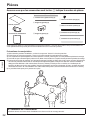
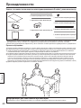
The work of fitting or removing the display must be performed by at least 4 people.
• The display may fall and cause injury.
For installation, use the special-purpose constituent parts.
• Otherwise, the display may fall off the wall, possibly causing injury.
During setting-up, tighten all screws securely.
• Inadequate assembly may fail to ensure sufficient strength, and cause falling or breaking of the product that results
in injury.
Always wear the supplied gloves when fitting or removing the product.
• Failure to do so may cause hand injuries as you fit or remove the product.
PROFESSIONAL INSTALLATION IS REQUIRED.
PANASONIC DISCLAIMS ANY PROPERTY DAMAGE AND/OR SERIOUS INJURY, INCLUDING DEATH
RESULTING FROM IMPROPER INSTALLATION OR INCORRECT HANDLING.
16
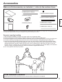
Accessories
Make sure that accessories are included. ( ) refers to the number of pcs.
㇙ Protective Glass (1)
㇜ Rubbers (thick / long) (2)
㇝ Rubbers (thick / short) (4)
㇠ Screws (10)
㇡ Non-woven fabrics (long) (2)
㇞ Brackets (large) (8)
㇚ Gloves (4 pairs)
㇟ Brackets (small) (2)
㇣ Rubbers (thin / long) (2)
English
㇛ Fitting Instructions
㇢ Non-woven fabrics (short) (4)
Rubbers (thin / short) (4)
^ Since the images shown above are for illustrative purposes only, they may differ in shape from the actual products.
^ The product specications may be changed at any time without prior notice.
Requests regarding handling
1) Take care during installation as shocks can cause ‘cracks’ to the Protective Glass.
2) Avoid scratching the Protective Glass, the display panel or the cabinet during the tting work.
3) To prevent ngerprints on the Protective Glass or the display panel, wear the supplied gloves ㇚ during the tting work.
4) To avoid scratching or damaging the product or the `oor, use a soft cloth(s) or sponge(s) during the tting work.
5) Care for the Protective Glass by wiping it gently with a soft, dry cloth (cotton or `annel). When the Protective Glass
surface is heavily soiled or marked with ngerprints, wipe it clean with a cloth that has been dampened with a neutral
detergent diluted with 100 parts of water and wrung out, and as a nishing touch, wipe with a dry cloth. Do not use
benzene, thinner, or furniture wax. (For information on how to care for the display unit, see the display unit’s instruction
manual. If using a chemically-treated cloth, follow the instructions supplied with the cloth.)
6) 4 or more people should carry the product.
To the Installation Contractor
^ Please give these Fitting Instructions to the customer after the fitting work is completed.
17
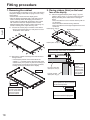
Fitting procedure
English
1. Removing the cabinet
Lay a soft cloth(s) or sponge(s) out on a flat, solid surface,
and put the display on the cloth or sponge in such a way
that it upturns.
• Remove dust or stains from the display panel.
• Wipe the display panel lightly with a soft cloth (such as
cotton or flannel). When the display panel surface is
heavily soiled or marked with fingerprints, wipe it clean
with a cloth that has been dampened with a neutral
detergent diluted with 100 parts of water and wrung out,
and as a finishing touch, wipe with a dry cloth.
1-1. Unscrew the screws (20) on all sides of the cabinet.
• Put the unscrewed screws in a safe place for use in
reinstallation of the cabinet.
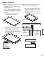
2. Placing rubbers (thick) on the bezel
face of the display
2-1. Place the supplied rubbers (thick / long) ㇜ (2) and
rubbers (thick / short) ㇝ (4) on the bezel face of the
display according to the order shown in the figure
below.
• Place the rubbers in such a manner that they will not
be stretched.
• Place the rubbers without leaving clearance.
• Place the rubbers to fit the right-angled section of the
bezel face.
Rubber (thick / long) ㇜
Rubber (thick / short) ㇝
ヂ
ツ
ヅ
テ
ッ
Rubber (thick / short) ㇝
デ
Rubber (thick / long) ㇜
Both ends of the upper / lower side rubbers must not extend
beyond the edge of the rubber on either side.
1-2. Remove the cabinet according to the order shown in
the figure below.
• A PC board is present on the lower side of the
cabinet ( ④ ). Carefully remove the lower side of the
cabinet and try not to place any load on the wire(s) of
the PC board. Go through the rest of the procedure,
leaving the wire(s) connected to the display.
Each of the right /
left side rubbers
must be
positioned in such
a way as to keep
its top and bottom
from lying off the
bezel aperture.
The upper / lower side
rubber (thick / short) ㇝
①
Upper side
The right / left side
rubber (thick / long) ㇜
③
④
Lower side
Be careful not to place
any load on the wire(s)
of the PC board while
removing the lower
side of the cabinet.
②
Place each rubber to t on the
bezel aperture so that it cannot lie
off the bezel aperture.
Rubber
The cross section of the display panel
18
3. Attaching the brackets to the display
4. Placing non-woven fabrics and
rubbers (thin) on the cabinet
3-1. Attach the brackets (large) ㇞ (8) and the brackets
(small ) ㇟ (2) to the cabinet fixing brackets of the
display with the supplied screws ㇠ (10), as shown in
the figures below.
(Tightening torque: 0.9 to 1.1 N • m)
Bracket (large) ㇞
Bracket (small) ㇟
Non-woven fabric (long) ㇡
Non-woven fabric
(short) ㇢
Non-woven fabric
(long) ㇡
Cabinet
Bracket
(large) ㇞
Rubber (thin / long)
㇣
Rubbers (thin / short)
Cabinet (upper side)
Bracket
(large) ㇞
Screw ㇠
Bracket (small) ㇟
Bracket (large) ㇞
Rubber (thin / long) ㇣
Cabinet
(lower side)
Non-woven
fabric (short)
㇢
How to attach the brackets (large) ㇞
English
4-1. Place the supplied six non-woven fabrics - non-woven
fabrics (long) ㇡ (2) and non-woven fabrics (short) ㇢
(4) - on the inner side surface of the cabinet.
4-2. Place the supplied six rubbers - rubbers (thin / long) ㇣
(2) and frubbers (thin / short) (4) - on the inner front
surface of the cabinet.
The installed position of a PC
board in the lower side cabinet
Cabinet
The center of the lower side cabinet
Screw ㇠
As shown in the gure, hook the bracket (large) ㇞ to the
corresponding cabinet xing bracket.
How to attach the brackets (small) ㇟
Non-woven fabric
Non-woven fabric
TY-PG70LF50
Screw ㇠
As shown in the gure, hook the bracket (small) ㇟ to the
corresponding cabinet xing bracket.
Rubber
Non-woven fabric
The rubber and non-woven fabric must
not stick out of the edge of the cabinet.
TY-PG80LF50
Rubber
Non-woven fabric
The rubber and non-woven fabric must
not stick out of the edge of the cabinet.
Non-woven fabric
Non-woven fabric
Rubber
Rubber
Placement
reference
Placement
reference
Placement
reference
Placement
reference
19
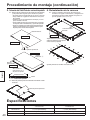
Fitting procedure (Continued)
5. Setting the Protective Glass on top of the display
5-1. Remove the protective film from the back side of the Protective
Glass, and set the Protective Glass on the rubbers that you
have placed on the display.
• 4 or more people should carry the product.
• Be careful not to hit the Protective Glass on the display panel.
• Ensure the Protective Glass is clean and free of dust, dirt or stains.
• Be careful to prevent dust or dirt from entering into the space
between the Protective Glass and the display panel.
• The side with the label is the back of the Protective Glass. Fit
the Protective Glass on the display in such a manner that the
label will be located at the lower left side.
6. Reinstalling the cabinet
6-1. Reinstall the cabinet in the order shown in the gure
below, and secure it with the screws (20) that you have
unscrewed in step 1-1.
(Tightening torque: 0.9 to 1.1 N • m)
④
Upper side
②
English
Cabinet positioning
Protective Glass
①
Lower side
③
Front side
Be careful not to trap the wire(s) of the PC
board between the cabinet and the display.
※
Back side
※
Remove the protective lm
Upper side
Protective
Glass ㇙
※
※
Label (back side)
Tighten those screws in the positions marked with ※ rst
Lower side
Align the outline of the
Protective Glass with
that of the display panel.
Protective Glass
Rubber
Display panel
5-2. Remove the protective film from the front side of the Protective
Glass.
Remove the protective film
Speci&cations
TY-PG80LF50
TY-PG70LF50
Dimensions
Weight
20
Transmittance
1564 mm (61.6”) (Width) × 900 mm (35.5”) (Height) 1819 mm (71.6”) (Width) × 1044 mm (41.1”) (Height)
× 1.3 mm (0.06”) (Thickness)
× 1.3 mm (0.06”) (Thickness)
Approx. 5 kg (Approx.11.0 lbs)
Approx. 6.5 kg (Approx.14.3 lbs)
Approx. 93 %
Sicherheitsmaßnahmen
WARNUNG
Die Montagearbeiten dürfen nur von qualifizierten Installationstechnikern ausgeführt werden.
• Falsches Zubehör kann zum Herunterfallen des Gerätes und zur Verletzung von Personen führen.
Nicht für Displays verwenden, die nicht in diesem Katalog aufgeführt sind.
• Andernfalls kann das Gerät herunterfallen und Verletzungen oder Schäden verursachen.
Installieren Sie das Display ausschließlich durch Befolgen der Arbeitsschritte wie in dieser Anleitung
angegeben: Installieren Sie es nicht auf andere Weise.
• Andernfalls kann das Gerät herunterfallen und Verletzungen oder Schäden verursachen.
Das Anbringen oder Abnehmen des Displays muss immer von mindestens 4 Personen ausgeführt werden.
• Das Display kann herunterfallen und Verletzungen verursachen.
Verwenden Sie zur Installation ausschließlich die Spezial-Befestigungsteile im Lieferumfang.
• Andernfalls kann das Display herunterfallen und Verletzungen verursachen.
Beim Aufstellen ziehen Sie alle Schrauben fest an.
• Falsche Montage kann dazu führen, dass keine ausreichende Stärke zum Tragen vorhanden ist und dazu führen,
dass das Produkt herunterfällt oder beschädigt wird und Verletzungen verursacht.
Tragen Sie immer die mitgelieferten Handschuhe beim Montieren oder Entfernen des Produkts.
• Wenn das unterlassen wird, besteht die Gefahr von Verletzungen an den Händen beim Montieren oder Entfernen
des Produkts.
DIE INSTALLATION IST PROFESSIONELL DURCHZUFÜHREN.
PANASONIC ÜBERNIMMT KEINE HAFTUNG FÜR SACHSCHÄDEN UND/ODER SCHWERE
VERLETZUNGEN, EINSCHLIESSLICH TODESFALL, DIE AUF UNSACHGEMÄSSE INSTALLATION ODER
FALSCHE HANDHABUNG ZURÜCKZUFÜHREN SIND.
Deutsch
VORSICHT
21
Zubehörteile
Stellen Sie sicher, dass die Zubehörteile im Lieferumfang vorhanden sind.
( ) bezieht sich auf die Anzahl der Teile.
㇙ Schutzglas (1)
㇜ Gummistücke (dick / lang) (2)
㇝ Gummistücke (dick / kurz) (4)
㇠ Schrauben (10)
㇡ Vliesstoffe (lang) (2)
㇞ Halterungen (groß) (8)
㇚ Handschuhe (4 Paare)
㇛ Montageanweisungen
㇢ Vliesstoffe (kurz) (4)
㇟ Halterungen (klein) (2)
㇣ Gummistücke (dünn / lang) (2)
Deutsch
Gummistücke (dünn / kurz) (4)
^ Die obigen Abbildungen dienen nur zur Erläuterung und können sich vom Aussehen des vorhandenen Produkts unterscheiden.
^ Änderungen der technischen Daten des Produkts bleiben jederzeit vorbehalten.
Vorsichtsmaßnahmen bei der Handhabung
1) Bei der Montage muss vorsichtig gearbeitet werden, da Erschütterungen zu “Rissen” im Schutzglas führen können.
2) Achten Sie bei der Montagearbeit darauf, das Schutzglas, den Bildschirm und das Gehäuse nicht zu zerkratzen.
3) Um Fingerabdrücke auf dem Schutzglas oder dem Bildschirm zu vermeiden tragen Sie bitte die mitgelieferten
Handschuhe ㇚ bei der Montagearbeit.
4) Um Zerkratzen oder Beschädigung des Produkts oder des Fußbodens zu vermeiden, verwenden Sie bei der
Montagearbeit nach Bedarf weiche Tücher oder Schwämme.
5) P`egen Sie das Schutzglas, indem Sie es vorsichtig mit einem weichen, trockenen Tuch (Baumwolle oder Flanell) abwischen. Wenn
die Ober`äche des Schutzglases stark verschmutzt ist oder Fingerabdrücke trägt, wischen Sie es mit einem weichen Tuch sauber,
das mit einem neutralen, mit 100 Teilen Wasser verdünnten, Spülmittel befeuchtet und gut ausgewrungen wurde, und wischen Sie
anschließend mit einem trockenen Tuch sauber. Keine Mittel wie Benzol, Verdünner oder Möbelwachs verwenden. (Informationen
zur P`ege der Displayeinheit nden Sie in der Bedienungsanleitung der Displayeinheit. Bei Verwendung eines chemisch
behandelten Reinigungstuchs sind die Anweisungen der dem Tuch beiliegenden Gebrauchsanweisung sorgfältig zu beachten.)
6) Das Produkt sollte von mindestens 4 Personen getragen werden.
Anweisungen an den Monteur
^ Bitte händigen Sie nach ausgeführter Montage diese Montageanweisungen dem Kunden aus.
22
Montageanweisungen
1. Entfernen des Gehäuses
Legen Sie weiche Tücher oder Schwämme auf eine
flache, solide Oberfläche, und platzieren Sie dann das
Display mit der Vorderseite nach unten darauf.
• Entfernen Sie Staub oder Flecken vom Bildschirm.
• Wischen Sie den Bildschirm leicht mit einem weichen,
trockenen Tuch (aus Baumwolle oder Flanell) ab. Wenn
die Oberfläche des Bildschirms stark verschmutzt ist
oder Fingerabdrücke trägt, wischen Sie es mit einem
weichen Tuch sauber, das mit einem neutralen, mit
100 Teilen Wasser verdünnten, Spülmittel befeuchtet und
gut ausgewrungen wurde, und wischen Sie anschließend
mit einem trockenen Tuch sauber.
1-1. Lösen Sie die Schrauben (20) auf allen Seiten des
Gehäuses.
• Legen Sie die gelösten Schrauben an einer sicheren
Stelle ab, um sie beim erneuten Anbringen des
Gehäuses wieder zu verwenden.
2. Gummistücke (dick) auf die
Fassungsfläche des Displays setzen
2-1. Setzen Sie die mitgelieferten Gummistücke (dick /
lang) ㇜ (2) und Gummistücke (dick / kurz) ㇝ (4) auf
die Fassungsfläche des Displays in der Reihenfolge
wie in der Abbildung unten gezeigt.
• Platzieren Sie die Gummistücke so, dass sie nicht
gedehnt werden.
• Platzieren Sie die Gummistücke, ohne Freiraum zu
lassen.
• Platzieren Sie die Gummistücke so, dass sie an die
rechtwinklige Sektion der Fassungsfläche passen.
Gummistück (dick / lang) ㇜
Gummistück (dick / kurz) ㇝
ヂ
ツ
ヅ
Deutsch
テ
ッ
Gummistück (dick / kurz) ㇝
デ
Gummistück (dick / lang) ㇜
Beide Enden der Gummistücke der oberen/unteren Seite dürfen nicht
über die Kante des Gummistücks auf beiden Seiten herausragen.
1-2. Entfernen Sie das Gehäuse in der Reihenfolge, wie in
der Abbildung unten gezeigt.
• Unten links am Gehäuse ( ④ ) befindet sich eine
Leiterplatte. Entfernen Sie vorsichtig die untere Seite
des Gehäuses und vermeiden Sie dabei, Drähte auf
der Leiterplatte zu belasten. Führen Sie die weiteren
Schritte des Verfahrens aus und lassen Sie die
Drähte am Display angeschlossen.
①
Oberseite
Beide Gummistücke
der rechten/linken
Seite müssen
auf solche Weise
positioniert werden,
dass ihre oberen
und unteren Enden
nicht über die
Fassungsblende
herausragen.
Das Gummistück der
oberen/unteren Seite
(dick / kurz) ㇝
Das Gummistück der
rechten/linken Seite
(dick / lang) ㇜
Setzen Sie alle Gummistücke so auf die
Fassungsblende, so dass sie nicht über
die Fassungsblende hinausragen können.
③
Gummistück
④
Unterseite
Achten Sie darauf,
die Drähte auf der
Leiterplatte nicht zu
belasten, während
Sie die Unterseite des
Gehäuses abnehmen.
②
Der Querschnitt des Bildschirms
23
Montageanweisungen (Fortsetzung)
3. Anbringen der Halterungen am Display 4. Auflegen von Vliesstofen und
3-1. Bringen Sie die Halterungen (groß) ㇞ (8)
Gummistücken (dünn) auf das
und die Halterungen (klein) ㇟ (2) an den
Gehäuse
Gehäusebefestigungshalterungen des Displays mit
den mitgelieferten Schrauben ㇠ (10) an, wie in der
Abbildung unten gezeigt.
(Anzugsmoment: 0,9 bis 1,1 N • m)
Halterung (groß) ㇞
Halterung (klein) ㇟
Vliesstoff (lang) ㇡
Halterung
(groß) ㇞
Vliesstoff
(kurz) ㇢
Gehäuse
Gummistück
(dünn / lang) ㇣
Gummistücke
(dünn / kurz)
Gehäuse (Oberseite)
Gummistück
(dünn / lang) ㇣
Halterung
(groß) ㇞
Schraube ㇠
Deutsch
4-1.Setzen Sie die mitgelieferten sechs Vliesstoffe Vliesstoffe (lang) ㇡ (2) und Vliesstoffe (kurz) ㇢ (4) auf die Innenfläche des Gehäuses.
4-2. Setzen Sie die mitgelieferten sechs Gummistücke Gummistücke (dünn / lang) ㇣ (2) und Gummistücke
(dünn / kurz) (4) - auf die Innenfläche des
Gehäuses.
Halterung (klein) ㇟
Halterung (groß) ㇞
Gehäuse
(Unterseite)
Vliesstoff
(kurz) ㇢
Anbringen der Halterungen (groß) ㇞
Die Einbauposition einer
Leiterplatte links im Gehäuse
Vliesstoff
(lang) ㇡
Gehäuse
Die Mitte des unteren
Seitengehäuses
Schraube ㇠
Wie in der Abbildung gezeigt haken Sie die Halterung (groß)
㇞ auf die entsprechende Gehäusebefestigungshalterung.
Anbringen der Halterungen (klein) ㇟
Vliesstoff
Vliesstoff
Schraube ㇠
Wie in der Abbildung gezeigt haken Sie die Halterung (klein)
㇟ auf die entsprechende Gehäusebefestigungshalterung.
TY-PG70LF50
Gummistück
Vliesstoff
Das Gummistück und der Vliesstoff dürfen nicht
aus der Kante des Gehäuses herausragen.
Gummistück
Vliesstoff
Gummistück
Gummistück
Platzierungsreferenz
Vliesstoff
Das Gummistück und der Vliesstoff dürfen nicht
aus der Kante des Gehäuses herausragen.
Vliesstoff
Platzierungsreferenz
24
TY-PG80LF50
Platzierungsreferenz Platzierungsreferenz
5. Aufsetzen des Schutzglases auf das Display
6. Wiederanbringen des Gehäuses
5-1. Nehmen Sie die Schutzfolie von der Rückseite des
Schutzglases ab und setzen Sie das Schutzglas auf die
Gummistücke, die Sie auf das Display gesetzt haben.
• Das Produkt sollte von mindestens 4 Personen getragen werden.
• Achten Sie darauf, dass das Schutzglas nicht gegen den
Bildschirm anstößt.
• Stellen Sie sicher, dass das Schutzglas sauber und frei von Staub,
Schmutz und Flecken ist.
• Achten Sie darauf, dass nicht Staub oder Schmutz in den Raum
zwischen dem Schutzglas und dem Bildschirm eindringen.
• Die Seite mit dem Aufkleber ist die Rückseite des Schutzglases.
Setzen Sie das Schutzglas derart auf das Display, dass der
Aufkleber auf der unteren linken Seite ist.
6-1. Bringen Sie das Gehäuse wieder in der Reihenfolge
an, wie in der Abbildung unten gezeigt, und sichern
Sie es mit den Schrauben (20), die Sie in Schritt 1-1
gelöst haben.
(Anzugsmoment: 0,9 bis 1,1 N • m)
④
Oberseite
②
Positionieren des Gehäuses
Schutzglas
①
Unterseite
Vorderseite
③
Rückseite
Deutsch
Achten Sie darauf, nicht Drähte von der
Leiterplatte zwischen dem Gehäuse und
dem Display einzuklemmen.
※
Die Schutzfolie abnehmen
※
Oberseite
Schutzglas ㇙
※
Aufkleber
(Rückseite)
※
Ziehen Sie die an den mit ※ markierten Positionen
bendlichen Schrauben zuerst fest.
Unterseite
Richten Sie den Umriss
des Schutzglases mit dem
des Bildschirms aust.
Schutzglas
Gummistück
Bildschirm
5-2. Nehmen Sie die Schutzfolie von der Vordersseite des
Schutzglases ab.
Die Schutzfolie abnehmen
Technische Daten
TY-PG70LF50
TY-PG80LF50
Abmessungen
1564 mm (Breite) × 900 mm (Höhe)
× 1,3 mm (Dicke)
1819 mm (Breite) × 1044 mm (Höhe)
× 1,3 mm (Dicke)
Gewicht
Ca. 5 kg
Ca. 6,5 kg
Durchlässigkeit
Ca. 93%
25
Precauzioni di sicurezza
AVVERTENZA
Le operazioni di montaggio non devono mai essere effettuate da persone diverse da tecnici adeguatamente
quali&cati.
• Un montaggio non corretto può comportare la caduta dell’apparecchio, con conseguenti possibili lesioni personali.
ATTENZIONE
Non utilizzare schermi diversi da quelli indicati nel catalogo.
• L’unità potrebbe altrimenti cadere danneggiandosi, e potrebbe causare incidenti alle persone.
Installare il televisore attenendosi esclusivamente a queste istruzioni. Non installarlo in altri modi.
• L’unità potrebbe altrimenti cadere danneggiandosi, e potrebbe causare incidenti alle persone.
Le operazioni di montaggio o rimozione dello schermo devono essere eseguite da almeno 4 persone.
• Lo schermo potrebbe cadere e causare infortuni.
Per l’installazione, usare le parti costituenti di uso speciale.
• In caso contrario, lo schermo potrebbe cadere dalla parete, causando possibili infortuni.
Durante l’installazione, serrare fermamente tutte le viti.
• Un assemblaggio non appropriato potrebbe indebolire la struttura, causando la caduta e il danneggiamento del
prodotto, con possibili infortuni.
Durante il montaggio o la rimozione del prodotto, indossare sempre i guanti in dotazione.
• La mancata osservanza di tale precauzione potrebbe provocare lesioni alle mani durante il montaggio o la
rimozione del prodotto.
Italiano
È NECESSARIA L’INSTALLAZIONE PROFESSIONALE.
PANASONIC NON È RESPONSABILE PER QUALSIASI DANNO DI PROPRIETÀ E/O GRAVE INFORTUNIO,
COMPRESA LA MORTE, CAUSATI DALL’INSTALLAZIONE SBAGLIATA O DAL MANEGGIAMENTO
SCORRETTO.
26
Accessori
Assicurarsi che gli accessori siano inclusi. ( ) indica il numero di pezzi.
㇙ Vetro di protezione (1)
㇜ Gommini (spessi/lunghi) (2)
㇝ Gommini (spessi/corti) (4)
㇠ Viti (10)
㇡ Tessuti non tessuti (lunghi) (2)
㇞ Staffe (grandi) (8)
㇚ Guanti (4 paia)
㇛ Istruzioni di montaggio
㇢ Tessuti non tessuti (corti) (4)
㇟ Staffe (piccole) (2)
㇣ Gommini (sottili/lunghi) (2)
Gommini (sottili/corti) (4)
Richieste relative alla manipolazione
1) Prestare attenzione durante l’installazione in quanto gli urti possono causare ‘incrinature’ al vetro di protezione.
2) Evitare di grafare il vetro di protezione, il pannello dello schermo o la struttura esterna durante le operazioni di montaggio.
3) Per evitare di lasciare impronte digitali sul vetro di protezione o sul pannello dello schermo, indossare i guanti in
dotazione ㇚ durante le operazioni di montaggio.
4) Per evitare di grafare o danneggiare il prodotto o il pavimento, utilizzare panni o spugne morbidi durante le operazioni di montaggio.
5) Trattare il vetro di protezione pulendolo delicatamente con un panno morbido e asciutto (cotone o `anella). Quando la
supercie del vetro di protezione è molto sporca o presenta molte impronte digitali, pulirla con un panno imbevuto in un
detergente neutro diluito con 100 parti di acqua e strizzato, e come tocco nale, asciugarla con un panno asciutto. Non
utilizzare benzene, solventi o cera per mobili. (per informazioni sulla manutenzione dello schermo, fare riferimento al
manuale di istruzioni dello schermo. Se si utilizza un panno trattato chimicamente, attenersi alle istruzioni).
6) Per il trasporto del prodotto sono necessarie almeno 4 persone.
Italiano
^ Poiché le immagini mostrate in precedenza sono soltanto a scopo illustrativo, i prodotti reali possono avere una
forma diversa da quelli mostrati in figura.
^ Le specifiche del prodotto possono essere modificate in qualsiasi momento senza preavviso.
Al tecnico addetto al montaggio
^ Consegnare queste istruzioni di montaggio al cliente al completamento delle operazioni di montaggio.
27
Procedura di montaggio
1. Rimozione della struttura esterna
Posizionare uno o più panni o spugne morbidi su una
superficie piatta e solida, quindi appoggiarvi lo schermo
rivolto verso l’alto.
• Rimuovere polvere o macchie dal pannello dello schermo.
• Pulire delicatamente il pannello dello schermo con un
panno morbido (come cotone o flanella). Quando la
superficie del pannello dello schermo è molto sporca o
presenta molte impronte digitali, pulirla con un panno
imbevuto in un detergente neutro diluito con 100 parti di
acqua e strizzato, e come tocco finale, asciugarla con un
panno asciutto.
1-1. Svitare le viti (20) su tutti i lati della struttura esterna.
• Conservare le viti in un posto sicuro per la
reinstallazione della struttura esterna.
2. Posizionamento dei gommini (spessi)
sulla cornice dello schermo
2-1. Posizionare i gommini in dotazione ㇜ (2) (spessi/
lunghi) e ㇝ (4) (spessi/corti) sulla cornice dello
schermo seguendo l’ordine indicato nella figura che
segue.
• Posizionare i gommini in modo che non subiscano
stiramenti.
• Posizionare i gommini senza lasciare alcun gioco.
• Posizionare i gommini in modo che si adattino alla
sezione ad angolo retto della cornice.
Gommino (spesso/lungo) ㇜
Gommino (spesso/corto) ㇝
ヂ
ツ
ヅ
テ
ッ
Gommino (spesso/corto) ㇝
デ
Gommino (spesso/lungo) ㇜
Italiano
Entrambe le estremità dei gommini del lato superiore e inferiore
non devono estendersi oltre il bordo del gommino su entrambi i lati.
1-2. Rimuovere la struttura esterna seguendo l’ordine
indicato nella figura che segue.
• Nel lato inferiore della struttura esterna è presente
una scheda PC ( ④ ). Rimuovere con cautela il lato
inferiore della struttura esterna e cercare di non
posizionare alcun carico sui fili della scheda PC.
Proseguire con il resto della procedura, lasciando i
fili collegati allo schermo.
①
Lato superiore
Tutti i gommini
dei lati destro e
sinistro devono
essere posizionati
in modo da evitare
che i relativi lati
superiori e inferiori
sporgano al di
fuori dell’apertura
della cornice.
Gommino lato superiore/
inferiore (spesso/corto) ㇝
Gommino lato destro/
sinistro (spesso/lungo) ㇜
③
④
Lato inferiore
Prestare attenzione a
non posizionare alcun
carico sui fili della
scheda PC durante
la rimozione del lato
inferiore della struttura
esterna.
28
Posizionare ogni gommino in modo
che si adatti all’apertura della cornice,
senza sporgere al di fuori di essa.
②
Gommino
Sezione trasversale del pannello dello schermo
3-1. Fissare le staffe (grandi) ㇞ (8) e le staffe (piccole)
㇟ (2) alla struttura esterna fissando le staffe dello
schermo con le viti in dotazione ㇠ (10), come indicato
nella figura che segue.
(coppia di serraggio: da 0,9 a 1,1 N • m).
Staffa (grande) ㇞
Staffa (piccola) ㇟
Staffa
(grande) ㇞
4. Posizionamento dei tessuti non
tessuti e dei gommini (sottili)
sulla struttura esterna
4-1. Posizionare i sei tessuti non tessuti in dotazione tessuti non tessuti (lunghi) ㇡ (2) e tessuti non tessuti
(corti) ㇢ (4) - sulla superficie interna della struttura
esterna.
4-2. Posizionare i sei gommini in dotazione - gommini
(sottili/lunghi) ㇣ (2) e gommini (sottili/corti) (4)
- sulla superficie anteriore interna della struttura
esterna.
Tessuto non tessuto (lungo) ㇡
Staffa
(grande) Struttura esterna
㇞
Gommino (sottile/
lungo) ㇣
Vite ㇠
Staffa (piccola) ㇟
Gommini (sottili/corti)
Struttura esterna
(lato superiore)
Gommino (sottile/lungo) ㇣
Staffa (grande) ㇞
Come ssare le staffe (grandi) ㇞
Vite ㇠
Seguendo quanto indicato in gura, agganciare la staffa
(grande) ㇞ alla relativa staffa di ssaggio della struttura
esterna.
Struttura
esterna (lato
inferiore)
Tessuto non
tessuto (corto) ㇢
Tessuto non
tessuto (lungo) ㇡
Tessuto non
tessuto (corto)
㇢
Posizione di installazione di una scheda
PC nella struttura esterna del lato inferiore
Struttura esterna
Centro della struttura esterna del
lato inferiore
Italiano
3. Fissaggio delle staffe allo schermo
Come ssare le staffe (piccole) ㇟
Tessuto non tessuto
Vite ㇠
Seguendo quanto indicato in gura, agganciare le staffe
(piccole) ㇟ alla relativa staffa di ssaggio della struttura
esterna.
Tessuto non tessuto
TY-PG70LF50
Gommino
Tessuto non tessuto
Il gommino e il tessuto non tessuto non devono
sporgere dal bordo della struttura esterna.
TY-PG80LF50
Gommino
Tessuto non tessuto
Il gommino e il tessuto non tessuto non devono
sporgere dal bordo della struttura esterna.
Tessuto non tessuto
Tessuto non tessuto
Gommino
Gommino
Riferimento per il
posizionamento
Riferimento per il
posizionamento
Riferimento per il
posizionamento
Riferimento per il
posizionamento
29
Procedura di montaggio (segue)
5. Installazione del vetro di protezione sullo schermo 6. Reinstallazione della struttura esterna
5-1. Rimuovere la pellicola protettiva dal lato posteriore del vetro di
protezione, quindi appoggiare il vetro di protezione sui gommini
precedentemente posizionati sullo schermo.
• Per il trasporto del prodotto sono necessarie almeno 4 persone.
• Prestare attenzione a non urtare il vetro di protezione contro il
pannello dello schermo.
• Assicurarsi che il vetro di protezione sia pulito e privo di polvere,
sporco o macchie.
• Evitare che la polvere o lo sporco entrino nello spazio tra il
vetro di protezione e il pannello dello schermo.
• Il lato con l’etichetta è il retro del vetro di protezione. Applicare
il vetro di protezione allo schermo in modo che l’etichetta sia
posizionata in basso a sinistra.
6-1. Reinstallare la struttura esterna seguendo l’ordine
indicato nella gura che segue, quindi ssarla con le
viti (20) che sono state svitate nel passaggio 1-1.
(coppia di serraggio: da 0,9 a 1,1 N • m).
④
②
Posizionamento della struttura esterna
①
Vetro di protezione
Lato anteriore
Lato superiore
Lato inferiore
③
Prestare attenzione a non inciampare nei fili della
scheda PC tra la struttura esterna e lo schermo.
※
Lato posteriore
Italiano
※
Rimuovere la pellicola protettiva
Lato superiore
※
Vetro di
protezione ㇙
※
Serrare prima le viti nelle posizioni contrassegnate con ※
Etichetta
(lato posteriore)
Lato inferiore
Allineare il profilo del vetro
di protezione con quello del
pannello dello schermo.
Vetro di protezione
Gommino
Pannello dello schermo
5-2. Rimuovere la pellicola protettiva dal lato anteriore del vetro di protezione.
Rimuovere la pellicola protettiva
Speci&che
30
TY-PG70LF50
TY-PG80LF50
Dimensioni
1.564 mm (larghezza) × 900 mm (altezza)
× 1,3 mm (spessore)
1.819 mm (larghezza) × 1.044 mm (altezza)
× 1,3 mm (spessore)
Peso
Circa 5 kg
Circa 6,5 kg
Trasmittanza
Circa 93%
Précautions de sécurité
Avertissement
Les opérations de montage ne doivent être réalisées que par un installateur compétent.
• Un montage incorrect peut provoquer la chute de l’appareil et partant une blessure.
PRÉCAUTIONS
N’utilisez pas d’autres écrans que ceux mentionnés dans le catalogue.
• Sinon, l’écran pourrait se décrocher du mur, ce qui pourrait causer des blessures.
Pour l’installation, procédez en suivant uniquement les étapes indiquées dans ces instructions : ne
procédez d’aucune autre manière.
• Sinon, l’écran pourrait se décrocher du mur, ce qui pourrait causer des blessures.
Les opérations de montage ou de dépose de l’écran doivent être effectuées par 4 personnes au moins.
• L’écran pourrait tomber en entraînant des blessures.
Pour l’installation, utilisez les composants spécialisés.
• En cas contraire, l’écran pourrait tomber et se détériorer en blessant des personnes.
Pendant le réglage, serrez bien toutes les vis.
• Un montage inapproprié peut mener à un manque de résistance et provoquer la chute ou la rupture du produit,
entraînant des blessures.
Lors du montage ou de la dépose du produit, portez toujours les gants fournis.
• À défaut, vous pourriez vous blesser aux mains lorsque vous posez ou déposez le produit.
Français
L’INSTALLATION PAR UN PROFESSIONNEL EST INDISPENSABLE.
PANASONIC DECLINE TOUT DOMMAGE MATERIEL ET/OU BLESSURE GRAVE, Y COMPRIS LA MORT
RESULTANT D’UNE INSTALLATION OU D’UNE MANIPULATION INCORRECTE.
31
Pièces
Assurez-vous que les accessoires sont inclus. ( ) indique le nombre de pièces.
㇙ Vitre de protection (1)
㇜ Caoutchoucs (épais/longs) (2)
㇝ Caoutchoucs (épais/courts) (4)
㇠ Vis (10)
㇡ Tissus non tissés (longs) (2)
㇞ Supports (grands) (8)
㇚ Gants (4 paires)
㇛ Instructions d’installation
㇢ Tissus non tissés (courts) (4)
㇟ Supports (petits) (2)
㇣ Caoutchoucs (fins/longs) (2)
Caoutchoucs (fins/courts) (4)
^ Les images ci-dessus ne sont présentées qu’à titre d’illustration ; la forme des produits réels peut être différente.
^ Les spécifications du produit peuvent être modifiées à tout moment sans préavis.
Français
Précautions de manipulation
1) Faites attention pendant l’installation, car des chocs peuvent ‘ssurer’ la vitre de protection.
2) Évitez de rayer la vitre de protection, l’écran ou le boîtier pendant les opérations de montage.
3) Pour empêcher les empreintes digitales sur la vitre de protection ou l’écran, portez les gants ㇚ fournis pendant les opérations de montage.
4) Pour éviter de rayer ou d’endommager le produit ou le sol, utilisez un tissu moelleux ou un tapis de mousse pendant les opérations de montage.
5) Prenez soin de la vitre de protection en l’essuyant doucement à l’aide d’un chiffon doux et sec (coton ou feutre). Si la surface
de la vitre de protection est très sale ou est marquée d’empreintes digitales, essuyez-la à l’aide d’un chiffon humidié d’un
détergent neutre dilué dans 100 volumes d’eau et essoré ; nissez par l’essuyer avec un chiffon sec. N’utilisez pas de
benzène, de diluant ou de cire pour meubles. (Pour des informations sur les soins à apporter à l’écran, consultez le manuel
d’instruction de l’écran. En cas d’utilisation d’un chiffon traité chimiquement, suivez les instructions fournies avec le chiffon.)
6) Le produit doit être porté par 4 personnes ou plus.
À l’intention de l’installateur
^ Veuillez donner ces Instructions d’installation au client une fois le montage terminé.
32
Mode de pose
1. Dépose du boîtier
Étendez un tissu moelleux ou un tapis de mousse sur une
surface plane et ferme, puis posez l’écran dessus de sorte
qu’il soit orienté vers le haut.
• Éliminez toute poussière et toute tache de l’écran.
• Essuyez doucement l’écran à l’aide d’un chiffon doux (en
coton ou en feutre). Si la surface de l’écran est très sale
ou est marquée d’empreintes digitales, essuyez-la à l’aide
d’un chiffon humidifié d’un détergent neutre dilué dans
100 volumes d’eau et essoré ; finissez par l’essuyer avec
un chiffon sec.
1-1. Retirez les vis (20) de tous les côtés du boîtier.
• Conservez ces vis en lieu sûr pour pouvoir les
réutiliser lors du remontage du boîtier.
2. Mise en place des caoutchoucs
(épais) sur la lunette de l’écran
2-1. Placez les caoutchoucs (épais/longs) ㇜ (2) et les
caoutchoucs (épais/courts) ㇝ (4) fournis sur la lunette
de l’écran, selon l’ordre indiqué à la figure ci-dessous.
• Placez les caoutchoucs de sorte qu’ils ne soient pas
tendus.
• Placez les caoutchoucs sans jeu.
• Placez les caoutchoucs de sorte qu’ils s’adaptent à
l’angle de la lunette.
Caoutchouc (épais/long) ㇜
Caoutchouc (épais/court) ㇝
ヂ
ツ
ヅ
テ
ッ
Caoutchouc (épais/
court) ㇝
デ
Caoutchouc (épais/long) ㇜
1-2. Retirez le boîtier en suivant l’ordre indiqué à la figure
ci-dessous.
• Une carte informatique se trouve dans la partie
inférieure du boîtier ( ④ ). Déposez la partie
inférieure du boîtier avec soin et essayez de ne
soumettre le ou les câbles de cette carte à aucune
charge. Poursuivez ces opérations en laissant le ou
les câbles branchés à l’écran.
①
Partie supérieure
③
④
Partie inférieure
②
Les caoutchoucs de
droite/gauche doivent
être positionnés de
manière que leurs
extrémités supérieure
et inférieure ne
dépassent pas
l’ouverture de la lunette.
Caoutchouc (épais/court)
supérieur/inférieur ㇝
Caoutchouc (épais/long)
de droite/gauche ㇜
Français
Les deux extrémités des caoutchoucs supérieur/inférieur ne
doivent dépasser la partie en caoutchouc ni d’un côté, ni de l’autre.
Adaptez chaque caoutchouc à
l’ouverture de la lunette de sorte
qu’il ne dépasse pas celle-ci.
Caoutchouc
Prenez soin de ne
soumettre le ou les
câbles de la carte
informatique à
aucune charge lors de
la dépose de la partie
inférieure du boîtier.
Section de l’écran
33
Mode de pose (suite)
3. Fixation des supports à l’écran
4. Mise en place des tissus non
tissés et des caoutchoucs (fins)
sur le boîtier
3-1. Fixez les supports (grands) ㇞ (8) et les supports
(petits) ㇟ (2) aux rails de fixation du boîtier de l’écran
à l’aide des vis ㇠ (10) fournies, comme l’indiquent les
figures ci-dessous.
(Couple de serrage : 0,9 à 1,1 N • m)
4-1. Placez les six tissus non tissés fournis [tissus non
tissés (longs) ㇡ (2) et tissus non tissés (courts) ㇢ (4)
sur la surface intérieure du boîtier.
4-2. Placez les six caoutchoucs fournis caoutchoucs (fins/
longs) ㇣ (2) et caoutchoucs (fins/courts) (4) sur la
surface avant intérieure du boîtier.
Support (grand) ㇞
Support (petit) ㇟
Tissu non tissé (long) ㇡
Support
(grand) ㇞
Tissu non tissé
(court) ㇢
Tissu non tissé
(long) ㇡
Boîtier
Caoutchouc
(fin/long) ㇣
Caoutchoucs (ns/courts)
Boîtier (partie supérieure)
Support
(grand) ㇞
Vis ㇠
Support (petit) ㇟
Support (grand) ㇞
Boîtier
(partie
inférieure)
Comment xer les supports (grands) ㇞
Caoutchouc (fin/long) ㇣
Tissu
non tissé
(court) ㇢
Position de la carte informatique
dans la partie inférieure du boîtier
Boîtier
Milieu de la partie inférieure du
boîtier
Français
Vis ㇠
Comme l’indique la gure, accrochez le support (grand) ㇞ au
rail de xation correspondant du boîtier.
Comment xer les supports (petits) ㇟
Tissu non tissé
Tissu non tissé
Vis ㇠
Comme l’indique la gure, accrochez le support (petit) ㇟ au
rail de xation correspondant du boîtier.
TY-PG70LF50
Caoutchouc
Tissu non tissé
Le caoutchouc et le tissu non tissé
ne doivent pas dépasser du boîtier.
Caoutchouc
Tissu non tissé
Le caoutchouc et le tissu non tissé
ne doivent pas dépasser du boîtier.
Tissu non tissé
Tissu non tissé
Caoutchouc
Caoutchouc
Référence pour le
positionnement
34
TY-PG80LF50
Référence pour le
positionnement
Référence pour le
positionnement
Référence pour le
positionnement
5. Montage de la vitre de protection sur l’écran 6. Remontage du boîtier
5-1. Retirez la pellicule de protection à l’arrière de la vitre
de protection, puis posez la vitre de protection sur les
caoutchoucs que vous avez placés sur l’écran.
• Le produit doit être porté par 4 personnes ou plus.
• Prenez soin de ne pas heurter l’écran avec la vitre de protection.
• Assurez-vous que la vitre de protection est propre et exempte de
poussière, de saleté et de taches.
• Prenez soin d’empêcher que de la poussière ou de la saleté ne
pénètre dans l’espace séparant la vitre de protection et l’écran.
• Le côté où est apposée l’étiquette est l’arrière de la vitre de
protection. Posez la vitre de protection sur l’écran de telle
sorte que l’étiquette se trouve du côté inférieur gauche.
6-1. Remontez le boîtier dans l’ordre indiqué à la gure
ci-dessous, puis xez-le avec les vis (20) que vous
avez retirées à l’étape 1-1.
(Couple de serrage : 0,9 à 1,1 N • m)
④
Dessus
②
Positionnement du boîtier
①
Vitre de protection
Dessous
Avant
③
Prenez soin de ne pas piéger le ou les câbles
de la carte informatique entre le boîtier et l’écran.
※
Arrière
※
Retirez la pellicule de protection
Dessus
※
※
Serrez d’abord les vis aux points marqués du symbole ※ .
Étiquette (arrière)
Dessous
Français
Vitre de
protection ㇙
Alignez le périmètre de
la vitre de protection
avec celui de l’écran.
Vitre de protection
Caoutchouc
Écran
5-2. Retirez la pellicule de protection de l’avant de la vitre de protection.
Retirez la pellicule de
protection
Spéci&cations
TY-PG70LF50
TY-PG80LF50
Dimensions
1564 mm (largeur) × 900 mm (hauteur)
× 1,3 mm (épaisseur)
1819 mm (largeur) × 1044 mm (hauteur)
× 1,3 mm (épaisseur)
Poids
Environ 5 kg
Environ 6,5 kg
Facteur de transmission
Environ 93 %
35
Precauciones para su seguridad
ADVERTENCIA
El montaje debe realizarlo solamente un instalador especializado con título.
• Una instalación mal hecha puede ser la causa de que el equipo se caiga y cause lesiones.
PRECAUCIÓN
No utilice ninguna pantalla distinta de las indicadas en el catálogo.
• De lo contrario, la unidad podría caerse y dañarse, y podrían producirse lesiones a personas.
Instale la pantalla siguiendo únicamente los pasos especificados en estas instrucciones: No la instale de
ninguna otra forma.
• De lo contrario, la unidad podría caerse y dañarse, y podrían producirse lesiones a personas.
El trabajo de instalar o desinstalar la pantalla deberá ser realizado por 4 personas como mínimo.
• La pantalla podría caerse y causar lesiones.
Para hacer la instalación, utilice las piezas componentes para propósitos especiales.
• De lo contrario, la pantalla podría descolgarse de la pared, provocando posibles lesiones.
Durante la instalación, apriete todos los tornillos de forma segura.
• Un ensamblaje frágil o incorrecto puede no garantizar la solidez necesaria y ser causa de caídas o roturas del
producto que a su vez pueden producir heridas o lesiones.
Póngase siempre los guantes que se proporcionan como accesorio durante el montaje o desmontaje del
producto.
• De no ser así podría sufrir heridas o lesiones en las manos al montar o desmontar el producto.
Español
LA INSTALACIÓN NECESITA SER REALIZADA POR PROFESIONALES.
PANASONIC NO SE HACE RESPONSABLE DE NINGÚN DAÑO CAUSADO EN PROPIEDADES NI
TAMPOCO DE LESIONES GRAVES, INCLUYENDO LA MUERTE, DEBIDOS A LA MALA INSTALACIÓN O
ALMANEJO INCORRECTO.
36
Accesorios
Compruebe que están incluidos todos los accesorios. ( ) se re&ere al número de piezas.
㇙ Cristal Protector (1)
㇜ Gomas (gruesas y largas) (2)
㇝ Gomas (gruesas y cortas) (4)
㇠ Tornillos (10)
㇡ Material textil no tejido (largo) (2)
㇞ Soportes (grandes) (8)
㇚ Guantes (4 pares)
㇛ Instrucciones de montaje
㇢ Material textil no tejido (corto) (4)
㇟ Soportes (pequeños) (2)
㇣ Gomas (finas y largas) (2)
Gomas (finas y cortas) (4)
^ Las imágenes que se muestran sobre estas líneas tienen una función ilustrativa y por ello su forma puede diferir
de los productos actuales.
^ Las especificaciones de producto pueden cambiarse en cualquier momento sin advertencia previa.
Consideraciones en relación al manejo
Español
1) Tenga cuidado durante la instalación, los impactos o las sacudidas pueden agrietar el Cristal Protector.
2) Evite rayar el Cristal Protector, el panel de la pantalla o la carcasa durante los trabajos de montaje.
3) Para evitar las huellas en el Cristal Protector o el panel de la pantalla, póngase los guantes que se proporcionan como
accesorio ㇚ durante el trabajo de montaje.
4) Para evitar rayar o dañar tanto el producto como el suelo, utilice un paño suave o una esponja durante el montaje.
5) Cuide el Cristal Protector limpiándolo cuidadosamente con un paño suave (de algodón o franela) y seco. Si la
supercie del Cristal Protector está muy sucia o tiene huellas de dedos, límpiela con un paño que se haya humedecido
con una solución de un detergente neutro en 100 partes de agua y se haya escurrido bien, pasándole después un
paño seco. No utilice bencina, disolvente o cera para madera. (Para encontrar información sobre cómo cuidar la
unidad de pantalla, acuda al manual de instrucciones de la misma. Si utiliza un paño tratado químicamente, siga las
instrucciones suministradas con el paño.)
6) El producto debe ser transportado por, al menos, 4 personas.
Para el instalador
^ Por favor, entregue estas Instrucciones de montaje al cliente una vez que haya terminado el trabajo de instalación.
37
Procedimiento de montaje
1. Retirada de la carcasa
Extienda un paño o esponja en una superficie plana y
firme, y coloque la pantalla encima hacia arriba.
• Quite el polvo y las manchas del panel de la pantalla.
• Limpie cuidadosamente el panel de la pantalla con un
paño suave (de algodón o franela). Si la superficie del
panel de la pantalla está muy sucia o tiene huellas de
dedos, límpiela con un paño que se haya humedecido
con un una solución de un detergente neutro en 100
partes de agua y se haya escurrido bien, pasándole
después un paño seco.
1-1. Retire los tornillos (20) de todos los lados de la
carcasa.
• Coloque los tornillos en un lugar seguro para volver
a utilizarlos cuando reinstale la carcasa.
2. Colocación de las gomas
(gruesas) en la cara biselada de
la pantalla
2-1. Coloque las gomas que se proporcionan como
accesorio: gomas (gruesas y largas) ㇜ (2) y
gomas (gruesas y cortas) ㇝ (4) en la cara biselada
de la pantalla tal como se muestra en la figura a
continuación.
• Coloque las gomas de forma que no sea necesario
estirarlas.
• Coloque las gomas sin dejar espacios.
• Coloque las gomas de forma que se fijen a la
sección en ángulo recto de la cara biselada.
Goma (gruesa y larga) ㇜
Goma (gruesa y corta) ㇝
ヂ
ツ
ヅ
テ
ッ
Goma (gruesa y corta) ㇝
デ
Goma (gruesa y larga) ㇜
Los extremos de las gomas de los lados superior e inferior
no deben extenderse más allá del borde de la goma en
ninguno de los lados.
Español
1-2. Retire la carcasa siguiendo el orden que se muestra
en la figura a continuación.
• Hay una tarjeta de circuito impreso en el lado inferior
de la carcasa ( ④ ). Retire con cuidado el lado
inferior de la carcasa y procure no colocar ninguna
carga en el cable o cables de la tarjeta de circuito
impreso. Continúe el procedimiento dejando el cable
o cables conectados con la pantalla.
①
Lado superior
Cada una de las
gomas de los
lados derecho e
izquierdo tiene
que colocarse de
tal forma que sus
extremos inferior
y superior no
se salgan de la
apertura del bisel.
La goma del lado superior/
inferior (gruesa y corta) ㇝
③
La goma del lado
derecho/izquierdo (gruesa
y larga) ㇜
④
Lado inferior
Tenga cuidado de no
colocar ninguna carga
en el cable o cables
de la tarjeta de circuito
impreso al retirar el
lado inferior de la
carcasa.
38
②
Coloque cada goma de forma
que se acomode en la apertura
del bisel y no sobresalga de la
misma.
Goma
Sección transversal del
panel de la pantalla
3. Colocación de los soportes en la
pantalla
3-1. Fije los soportes (grandes) ㇞ (8) y los soportes
(pequeños) ㇟ (2) a los soportes de montaje de
la carcasa de la pantalla con los tornillos que se
proporcionan como accesorios ㇠ (10), tal como se
muestra en las figuras a continuación.
(Couple de serrage : 0,9 à 1,1 Nm)
Soporte (grande) ㇞
4. Colocación del material textil no
tejido y las gomas (finas) en la
carcasa
4-1. Coloque las seis piezas de material textil no tejido
que se proporcionan como accesorios: material textil
no tejido (largo) ㇡ (2) y material textil no tejido (corto)
㇢ (4) - en la cara interior de la carcasa.
4-2. Coloque las seis gomas que se proporcionan como
accesorios: gomas (finas y largas) ㇣ (2) y gomas
(finas y cortas) (4) - en la superficie frontal interior
de la carcasa.
Soporte (pequeño) ㇟
Material textil no tejido (largo) ㇡
Soporte
(grande) ㇞
Material textil no
tejido (corto) ㇢
Material textil no
tejido (largo) ㇡
Carcasa
Goma (fina y larga)
㇣
Gomas (nas y cortas)
Carcasa (lado superior)
Soporte
(grande)
㇞
Tornillo ㇠
Soporte (pequeño) ㇟
Soporte (grande) ㇞
Goma (fina y larga) ㇣
Carcasa
(lado inferior)
Material textil
no tejido
(corto) ㇢
Cómo jar los soportes (grandes) ㇞
La posición de instalación de la tarjeta de
circuito impreso en la parte inferior de la
carcasa
Carcasa
El centro de la parte inferior de la
carcasa
Tornillo ㇠
Tal como se muestra en la gura, enganche el soporte
(grande) ㇞ al correspondiente soporte de montaje de la
carcasa.
Cómo jar los soportes (pequeños) ㇟
Material textil no tejido
TY-PG70LF50
Tornillo ㇠
Tal como se muestra en la gura, enganche el soporte (pequeño)
㇟al correspondiente soporte de montaje de la carcasa.
Goma
Material textil no tejido
La goma y el material textil no tejido no
debe sobresalir del borde de la carcasa
TY-PG80LF50
Goma
Material textil no tejido
La goma y el material textil no tejido no
debe sobresalir del borde de la carcasa
Material textil no tejido
Material textil no tejido
Goma
Goma
Referencia de
colocación
Referencia de
colocación
Español
Material textil no tejido
Referencia de
colocación
Referencia de
colocación
39
Procedimiento de montaje (continuación)
5. Colocación del Cristal Protector encima de la pantalla 6. Reinstalación de la carcasa
5-1. Retire la película protectora de la parte trasera del Cristal Protector,
y coloque este sobre las gomas que ha colocado en la pantalla.
• El producto debe ser transportado por, al menos, 4 personas.
• Tenga cuidado de no golpear el Cristal Protector en el panel
de la pantalla.
• Asegúrese de que el Cristal Protector está limpio y no tiene
polvo, suciedad o manchas.
• Tenga cuidado para evitar que se introduzca polvo o suciedad
en el espacio entre el Cristal Protector y el panel de la pantalla.
• El lado con la etiqueta es la parte trasera del Cristal Protector.
Coloque el Cristal Protector en la pantalla de tal forma que la
etiqueta quede en el lado inferior izquierdo.
6-1. Vuelva a instalar la carcasa en la forma que se
muestra en la gura a continuación y asegúrela con
los tornillos (20) que había retirado en el paso 1-1.
(Par de apriete: 0,9 a 1,1 N • m)
④
Parte superior
②
Colocación de la
carcasa
Cristal Protector
①
③
Parte inferior
Lado frontal
Tenga cuidado de no pinzar el cable o
cables de la tarjeta de circuito impreso
entre la carcasa y la pantalla.
Lado trasero
※
Retire la película protectora
※
Parte superior
Cristal
Protector ㇙
Etiqueta
(parte trasera)
※
※
Apriete primero los tornillos marcados con ※
Parte inferior
Español
Alinee el borde del
Cristal Protector con el
del panel de la pantalla.
Cristal Protector
Goma
Panel de la pantalla
5-2. Retire la película protectora del lado frontal del Cristal
Protector.
Retire la película protectora
Especi&caciones
40
TY-PG70LF50
TY-PG80LF50
Dimensiones
1564 mm (Anchura) × 900 mm (Altura)
× 1,3 mm (Profundidad)
1819 mm (Anchura) × 1044 mm (Altura)
× 1,3 mm (Profundidad)
Peso
Aprox. 5 kg
Aprox. 6,5 kg
Transmitancia
Aprox. 93 %
' *
+9;<=+9;><;?;
? * *
$ @ * #
$ J
, $$X
J
$
[
J
*
J
* .
• , ! .
+9;<\];9;>;?;
? *^# *
, _X
$ *
% .
• , .
=
* ^ J *@J, *
: ?
* J
*@J
.
• , .
9@ * $
X *$ *$^ J 4 _.
• "! ' .
<$ *
$ *^# *
^ J*.
• ! , ! .
+
*
@ * #$
.
• ! ! # ! .
` J$ *
$ @ * $
X #
$ *_
, %$ J* *
.
• ' # .
8 ;88"; 8
;.
;%" PANASONIC 8
;
8
;8
" " > ; "/"" 8>
%, 8%
, ;">;<" 8<8
" "; 8
;" ""
";; ;".
41
+
=@
^, _ J* *
%$ X
*
. ` @% ( ) # _ .
㇙ (1)
㇜ 9#
*
( / ) (2) ㇠ `
(10)
㇝ 9#
*
( / ) (4)
㇡ + J
(
) (2)
㇞ {* @ (@^
) (8)
㇚ +_
(4 *)
㇛ * ㇢ + J
(
) (4)
㇟ {* @ (J^
) (2)
㇣ P#
*
(
/ ) (2)
9#
*
(
/ ) (4)
^ 1 #; $ ! , .
^
! $ $ .
+
@
$
1) , $
$ ‘’ .
2) , ! # $ , .
3) ! #, !, ㇚ .
4) # $ .
5) $ (
). $ !
$
1 ! ! #, ! $ $ (1 ! 100 ! ), ! $
, 1 . , . (< ! # .
# '# . ! #, .)
6) < 4 !.
[J
$ $ J #
^ , 1 # .
42
+ J
1. \$
*
$ # .
• $
.
• ; $
(, ).
!
$
1 !
! #, ! $ $ (1 ! 100
! ), ! $
, 1 .
1-1. (20), .
• ! –
.
2. 9#J
#
% *
(%) J *$
2-1. ( / ) ㇜ (2) ( / ) ㇝ (4) , .
• , $ .
• , ! .
• , ! # $ .
( / ) ㇝
( /
ヂ
) ㇜
ツ
ヅ
テ
ッ
( / ) ㇝
デ
( / ) ㇜
# , / , # , / .
①
③
,
! !
.
/ ( /
) ㇝
/ ( /
) ㇜
, ! .
④
8 ,
, ! - $
! .
1-2. 8 , .
• ! ( ④ ). ; , $
$
! . # .
②
9#
$ *
<
*$ *^ ##
43
+ J (*
)
3. +
*% @ *X
3-1. 8 ㇠ (10), , (1) ㇞ (8) ()
㇟ (2) , .
(% : 0,9 1,1 • )
(1) ㇞
() ㇟
(1) ㇞
4. 9#J
* J
#
%
* (
%) *
4-1. 1 $ ,
, – $
() ㇡ (2) $
() ㇢ (4) – .
4-2. 1 ,
– ( / ) ㇣ (2) ( / ) (4) – # .
$
() ㇡
(1) ㇞
㇠
( / ) ㇣
( / )
( )
( / ) ㇣
() ㇟
(1) ㇞
(1) ㇞
㇠
$
() ㇢
$
() ㇡
(
)
$
()
㇢
% !
, (1) ㇞ .
() ㇟
㇠
, () ㇟ .
TY-PG70LF50
.
.
% TY-PG80LF50
44
% % % 5. = #
*% *$
6. = * J
5-1. 8 $
, , .
• < 4 !.
• 8 .
• , ! ! , $
.
• 8 $
.
• 8 ' $
. ,
! ' .
6-1. $ , ,
$ (20), 1$ 1-1.
(% : 0,9 1,1 • )
④
②
> ①
# ③
, ! () ! .
※
8 ※
>
㇙
※
( )
※
! , ! ※
$
.
> < 5-2. 8 # $ .
8 ]%
_
%
TY-PG70LF50
TY-PG80LF50
1564 (1) × 900 ()
× 1,3 ()
1819 (1) × 1044 ()
× 1,3 ()
%
; 5 $
; 6,5 $
!
; 93 %
45
\ |}|~|
} JJ @ J J J .
• <* : :, / /*, /: 0).
;\{;9]=
{ @ * *@#.
• , /*: 0) ), / + / 0).
' J * #: @ J *#.
• , /*: 0) ), / + / 0).
<
* J 4 J J .
• < /*, / 0).
@ *#.
• , /: 0) ), / 0).
@ @ @ J* @#.
• /) 01)6 ))) / 5))6 /* +) 0).
J J @ @ * *#.
• ; 5)) 11 /6 / 0).
8=" %%< ;
.
PANASONIC, <8 ;
%8 <8 < 8< ; >
%¡= >" /%8
, 8;¢ ==< (=% ¡=
%<=.
46
J @
J @ J # ##. ( ) @ .
㇙ (1)
㇜ 9# ( / #) (2)
㇝ 9# ( / ) (4)
㇠ } (10)
㇡ +
J (#) (2)
㇞ { () (8)
㇚ * (4 *)
㇛ ㇢ +
J () (4)
㇟ { () (2)
㇣ 9# ( / #) (2)
9# ( / ) (4)
^ : 5)$ ) )$), / 5))6 )1)) 5
$1 0).
^ () $ / )
5
$)) 0).
1) ; 6
, ) // :1 +$))6 ‘’ 0).
2) ; :1 +$), ), / /6
.
3) :1 +$) ) / )
) / 01) /: /: ㇚ 6
.
4) ()) ) / /: 01), */ () $() 6
.
5) :1 +$) */, /*:/ 10 (/ :) 0)6)
. :1 +$) / )$ / )
) /:, 6 100 51$) : /* :: 10 0)6)
, 6
: 6: /*:/ 10 0)6)
.
, */1 £
6
. (<) 5) +) 01) )6 / */: /6
. $ / 56$ , )$ )$ */ 6
.)
6) ()) 4 5 .
J
^ ; * /: ) */ *1: )6)
.
47
J
1. {* *
/ */ () $() $ 5, ) :
/ */ : $: /6
.
• )$) 16 / 0)6)
.
• ) */ 0)6)
(/ :).
) 0)$ / )
) :,
6 100 51$) /*
:: + :: 10 0)
, 6: /*:/ 10 0)6)
.
1-1. 6 / :: * (20)
11) 6
.
• 1) : * /
/ 01) /))
/6
.
2. <
* # () 2-1. /: 6) (/k6 / *
) ㇜ (2)
+ 6) (/6 / //) ㇝ (4) 5)$ ) 1 )6 )$
$) $)
)6)
.
• 6) ) ) 1
$)
)6)
.
• 6) / / ) $)
)6)
.
• ")$ )6 6 *1 5)$) 01)
6) $)
)6)
.
6 (/6 / *
) ㇜
6 (/6 / //) ㇝
ヂ
ツ
ヅ
テ
ッ
6 (/6 / //) ㇝
デ
6 (/6 / *
) ㇜
6)6 : / 5 : / /:
6)6 $) .
1-2.
5$) 5)$ ) 1
11) 6
.
• / 6 ( ④ ) 5$) :
)$. c6 5$) : 11)
, /6 () 1/
0 /: 6
. 8()
$ :: 0 /, /:
+)) 6
.
①
: :
6)6 6 /
: /:
)-))
1/ : +
5 /
) 1
.
6)6
: / 5 :
(/6 / //) ㇝
6)6 6 /
: (/6 /
*
) ㇜
③
6) /: )-)) 1/ 01) $)
)6)
.
④
5$) :
48
6 5$)
: 11)
/6 1/
0 /
.
②
9#
+^ * @
3. { * @
3-1. 1) (0) ㇞ (8) + 1) ()1))
㇟ (2) 5$) 5)$ )$
* ㇠ (10) )6 ))1 1) ))6)
.
(
6 * ): 0,9 – 1,1 N • m)
1 (0) ㇞
1 ()1)) ㇟
4. +
J # () * #
4-1. /: - (*
) ㇡ (2) +
(//) ㇢ (4) – 6 )1)
/ $)
)6)
.
4-2. /: 6) - 6
()6)1 / *
) ㇣ (2) + 6
()6)1 / //) (4) – 6 6:
/ $)
)6)
.
(*
) ㇡
1
(0) ㇞
1
(0) ㇞
* ㇠
(//) ㇢
(*
) ㇡
6
()6)1 / *
) ㇣
6 ()6)1 / //)
(:: :)
1 ()1)) ㇟
1 (0) ㇞
(5$)
:)
1) (0) ㇞ ) +))
6 ()6)1 / *
) ㇣
(//) ㇢
/ 6
5$) : 0)
6 5$) :6
* ㇠
8 5)$, 1) (0) ㇞ +
) ))1 1) ))6)
.
1) ()1)) ㇟ ) +))
* ㇠
8 5)$, 1) ()1)) ㇟ +
) ))1 1) ))6)
.
TY-PG70LF50
6
6 6 $) .
6
6 6 $) .
6
6
;
5
)
TY-PG80LF50
;
5
)
;
5
)
;
5
)
49
J ()
5. * 6. {* 5-1. : ) :1 +$))6 / : , $ : 6$ :1
+$) 6
.
• ()) 4 5 .
• )$) :1 +$) : /6
.
• :1 +$) , 16, )), : / .
• :1 +$) )6 /6 )1) 16
))6 ) /:6
.
• ) :1 +$))6 .
5$) : )) 01) :1 +$)
$ ))6)
.
6-1.
5$) 5)$ ) 1
/ , 1-1 / 11)
: * (20) ))6)
.
(
6 * ): 0,9 – 1,1 N • m)
④
: :
②
0)
:1
+$)s
①
5$) :
③
6: :
+ /
/6 1 /*6
.
※
/ :
※
: ) 6
: :
:1
+$)s ㇙
※
※
(/ :)
; * ※ ))1) $)$ 0 *6
.
5$) :
:1 +$))6 :
)$)
/ 6
.
:1 +$)s
6
)
5-2. : ) :1 +$))6 6:
: 6
.
: ) 6
50
]%
*J
TY-PG70LF50
TY-PG80LF50
(1)
1564 ()) × 900 ())$))
× 1,3 (/6:)
1819 ()) × 1044 ())$))
× 1,3 (/6:)
%
. 5 $
. 6,5 $
()
$)1) '#)
. 93 %
*@ #%
++;9;<>;??
9@
# $ @ JX^ $ X_ @J
, [
J
[%$J
# J.
• ! ) ) .
|\];9;>;??
? *", #$X^$ % #.
• 1 ) ) ) #$ .
<$ J *$ ", $ % $%: X @ *@.
• 1 ) ) ) #$ .
= @
# J J *$ JX^ $ J 4 X^J
.
• =1 ) .
`
$ *^ _
.
• =1 ) ) ) .
+
@ # J #$ .
• )#) #) !
) )
1 .
+ _ $ @ # J J @ #
$ , %$^ J* *
.
• #)¤ #) ) ! .
%;
;" ";
"8 8==8
%".
;%= PANASONIC 8 =<;=<;8
= > <-= ;;< 8;8
=
/
; 8;>=
%", " 8%
, ; ¥ 8=<;% =<;=<;; %;
; ";; ;8;.
51
+
$
+$, J* *
%
^ *
*
$. = % ( ) ##_ ^^ .
㇙ %
(1)
㇜ J *
( / ) (2) ㇠
(10)
㇝ J *
( / ) (4)
㇡ \J
J () (2)
㇞ {*
^ @
(
) (8)
㇚ 9
(4 *
)
㇛ !" # $
㇢ \J
J () (4)
㇟ {*
^ @
(J^) (2)
㇣ J *
( / ) (2)
J *
( / ) (4)
^ ) ) ; ))
) , .
^
)!) )) - ! $ ).
9J" *$
1) ) ! ), ) ) ‘)’ ).
2) ) ! ) )
), $ , .
3) ) ! ) )
) ) ) ))
#), #), ) ㇚ .
4) ) ! ) )
) 1 ) )$,
’ .
5) ’ (
)). $ !
) ¤ )) )) #), !) !) $ !$ (1 ! 100 ! ), ) !) , )#) ) . , ! ) ). (< )#) $ ¤ . )#) #)
. ) ))! )#), .)
6) < ) ) 1 4 .
52
![J$ $ J" #"
^ , ) 1 ) )
#) )#) )¤).
'
1. J$ *
) ' ))
) ) )) #
$.
• ) ) ) .
• ; ) '
(, )).
) ! ) ¤ )) )) #), !)
!) $ !$ (1 ! 100 ! ), ) !)
, )#) )
.
1-1. ) $ (20), 1) ) )
.
• ) !) $ ) )# –
)
.
2. 9#J$ J
% *
(
%) J *$
2-1. 1 $) () / $)) ㇜
(2) ) $) () / )) ㇝ (4), , #) )), ) !.
• 1 $) , $! .
• 1 $) !, ) 1 ).
• 1 $) !, ) )#) ) ) #)
.
( / $) ㇜
( / ) ㇝
ヂ
ツ
ヅ
テ
ッ
( /
) ㇝
デ
( / $) ㇜
)#) $ , 1 / ,
) )#) $ ,
1 ! / )!.
1-2. >)) )), ) !.
• ) ) 1
( ④ ). ; ))
, $! )
)
) ) # ) )
1 ¤ .
>)!
,
),
)
- ) .
) ! / )!
() / $)) ㇜
1 $
!, )
#) .
③
④
) /
() / )) ㇝
J *
②
<
* *^ ##
①
) $)
)
1
!,
) )
) !
) #) .
53
' (*$)
3. +
$ *
^
% @ *$
4. 9#J$ J J J
% *
(
%) *
3-1. > $ $) ㇠ (10), , ¤ )) ()) ㇞ (8) ) )) ()) ㇟ (2) ) ) , !.
(% $: ) 0,9 1,1 • )
4-1. 1 1) $ $ ), , – $ $
) ($)) ㇡ (2) ) $ $ )
()) ㇢ (4) – )1) )!) ) .
4-2. 1 1) $ , – $) () /
$)) ㇣ (2) ) $) () / )) (4)
– )1) #) ) .
) () ㇞
) () ㇟
8$ $
) ($) ㇡
)
()
㇞
)
()
㇞
㇠
) () ㇟
) () ㇞
8$ $
) () ㇢
8$ $
) ($) ㇡
( / $) ㇣
) () / ))
( )
( / $) ㇣
(
)
8$ $
)
() ㇢
¤ )) ()) ㇞
%)# ) ) ㇠
, ) ) ()
㇞ )) ) ) .
¤ )) ()) ㇟
㇠
, ) ) () ㇟ )) ) )
.
8$ $ )
8$ $ )
TY-PG70LF50
TY-PG80LF50
8$
$ )
$
$ ) )
.
54
$
$ ) )
.
8$ $
)
8$ $
)
%) )
8$
$
)
%) )
%) )
%) )
5. =$ #%
*% *$ 6. `$ * J
5-1. >)) ) $
, ) ) $)
, ) ) .
• < ) ) 1 4 .
• .
• , ! ¤ ,
.
• , ) ) ) .
• 8 ¤ $ .
) !, 1 )!.
6-1. ) $ )# )),
) !, ) )) $ $ $) (20), ) #)
1-1.
(% $: ) 0,9 1,1 • )
④
②
) > ①
#
③
), ()) ) ) ¤.
※
>)) )
※
>
㇙
※
(
)
※
1 !$ $) $, )# 1 !) ) ※
) $ )
).
> < 5-2. >)) ) # $ .
>)) )
TY-PG70LF50
TY-PG80LF50
)
1564 (1) × 900 ()
× 1,3 ()
1819 (1) × 1044 ()
× 1,3 ()
%
5 $
6,5 $
)
93 %
]%_ %
55
Web Site : http://panasonic.net
© Panasonic Corporation 2012
M1012-0