1
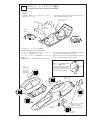
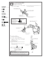
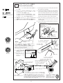
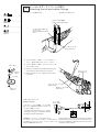
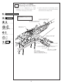
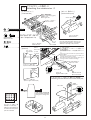
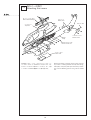
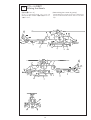
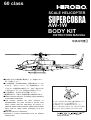
60 class
SCALE HELICOPTER
SUPERCOBRA
AW-1W
BODY KIT
INSTRUCTION MANUAL
取扱説明書
■組立前に必ずこの説明書を最後まで、よくお読みになり、
正しくお使い下さい。
■この説明書は「SUPERCOBRA」専用の部分についての
ものです。「60スケールシリーズ」共通の部分は、メカ
ニカルキット説明書をお読み下さい。特に「安全のため
に必ずお守り下さい」は、飛行前に必ず読んで下さい。
■この説明書は、大切にお手元に保管して下さい。
※製品改良のため、予告なく仕様を変更する場合があります。
■Please read this manual in its entirety before attempting
to assemble the helicopter.
■This manual explains the parts exclusive to
SUPERCOBRA. For parts common to the 60 scale
series, please read the mechanical kit manual. In
particular, please read the section entitled ’Always follow
these rules for safety’ before attempting to fly the
helicopter.
■Keep this manual in a safe place.
※Changes in product specifications may be effected
without notice.
マフラーは0414-263 S60-II後方排気マフラー
(ボックスタイプ)をご使用下さい。
その他のマフラーは使用できません。
Use a 0414-263 S60-II rear exhaust muffler
(box type). Other mufflers can not be used.
2002
MADE IN JAPAN
目 次
Contents
1
トップカバーの取付
........................................................... P.2
1
Attaching
the top cover ....................................................... P.2
2
スキッドの組立・アンダーカバーの加工
....................... P.3
2
Skid
assembly and undercover preparation ..................... P.3
3
テールスキッドの取付
....................................................... P.4
3
Attaching
the tail skid ......................................................... P.4
4
エアインテークの取付
....................................................... P.4
4
Attaching
the air intake....................................................... P.4
5
水平尾翼の取付
................................................................... P.4
5
Attaching
the horizontal tail fin .......................................... P.4
6
コクピット・トップカバーの組立
................................... P.5
6
Cockpit
and top cover assembly ........................................ P.5
7
アクセサリーの取付
-1 ....................................................... P.6
7
Attaching
the accessories-1 ................................................ P.6
8
テールギヤ
ASSY の組立 .................................................... P.7
8
Tail
gear assembly ............................................................... P.7
9
ドライブシャフトの組立
................................................... P.8
9
Drive
shaft assembly ........................................................... P.8
10
テールとラダーリンケージの取付
10
Attaching
the tail and rudder linkage ................................ P.9
11
Attaching
the main frame ................................................... P.10
11
メインフレームの取付
................................... P.9
....................................................... P.10
12
アクセサリーの取付
-2 ....................................................... P.11
12
Attaching
the accessories-2 ................................................ P.11
13
各カバーの取付
................................................................... P.12
13
Attaching
................................................................... P.13
14
Affixing
14
デカールの貼付
15
塗装について
....................................................................... P.14
the covers ........................................................... P.12
the decals ............................................................... P.13
15
Painting .................................................................................
P.14
補修パーツについて ............................................................... P.15
Repair parts .............................................................................. P.15
パーツリスト ........................................................................... P.16∼19
Parts list .................................................................................... P.16∼19
1
補強ベニヤ …………… 18
M2.6×6トラスTS………… 18
M2.6×6 truss TS
Attach the 18 screws (9 on each side).
① Referring to the figure, mark the position of the screws
on the bottom of the body with a marker pen etc.
② Attach a 10 × 10mm piece of reinforcement plywood
to the inside with epoxy (30 minute hardening type).
Sand the contact surfaces with sanding paper and wipe
any oil away with alcohol before attaching.
③ In order to ensure that the upper and lower halves of
the body fit together perfectly, use a file to file the
outside edge of the upper half of the body.
④ Fix the upper and lower halves of the body together
with masking tape.
⑤ Open a φ 1.8 hole as show in the figure, and attach
with a M2.6 truss TS. (Left and right simultaneously)
(Check that the front part of the body fits together
perfectly.)
⑥ Repeat the same operation towards the back of the
body.
Note: If the upper and lower halves of the body
are not fitted together perfectly, it may lead
to some skewness which can not be
corrected.
70
85
85
85
15
10
片側 9ヶ所、左右計 18 本のビスで取付けます。
① 図を参考に下部胴体に取付ビス位置をマジックペン
等で記します。
② 内側に補強ベニヤ 10 × 10mmを接着します。接着に
はエポキシ(30 分以上硬化型)を使用します。接着前
に接着面をサンドペーパーでサンディングし、アル
コールで油分を拭きとります。
③ 上部下部胴体がピッタリ合う様に上部胴体外周をヤ
スリ等で修正します。
④ マスキングテープ等で上下胴体を固定します。
⑤ 図の部分にφ 1.8 の穴をあけ、M2.6トラス TS で取付
けます。
(左右同時)
(上部下部胴体の前側が、ピッ
タリ合っている事を確認してください)
⑥ 後の方へ順々に同じ作業を行います。
注:しっかり上下を固定してから作業しないと歪み
が出て修正出来なくなります。
20
10
トップカバーの取付
Attaching the top cover
4
1
45
65
35
100
330
10
前から順に穴あけをします。
Open the holes starting at the front
and working towards the back.
注意 Caution
トップカバーとボディがぴったりと合う様に合わせ面をヤスリ等で
修正します。
In order to ensure that the top cover and body fit together perfectly, use a file to file the contact edges.
φ 10
スターターシャフト式の場合はスター
ターシャフト用の穴φ10をトップカバー
にあけます。
In the case of a stator shaft model, open a
stator shaft φ 10 hole in the top cover.
53.5mm
スーパーコブラはトウコブラと共通のアクセサリーを
使っておりますので実機では使われていないパーツがあ
ります。
お好みによって本文中の説明に従って取付けて下さい。
2
Since the Super Cobra and Tow Cobra use the same
accessories, there may be some parts which are not
needed.
Follow the instructions according to your preferences.
スキッドの組立・アンダーカバーの加工
Skid assembly and undercover preparation
2
M3×5SS ………………… 8
8mm
カットします
Cut 8mm
M2.6×6トラスTS ………… 8
M2.6×6 truss TS
防振ゴム
Shock absorbing
rubber
組立後瞬間接着剤
を使用します。
Use cyanoacrylate
glue after
assembling.
M3×8TS ………………… 8
+
CA
PA
CE
R
瞬間接着剤
Cyanoacrylate glue
195
40
90°
90°
64mm
ボディとぴったり合う様にアンダーカバーを
ヤスリ等で修正します。
In order to ensure that it fits the body perfectly,
use a file to file the undercover.
直径 16mm
(スキッドの取付けに合わせてカットする)
Diameter 16mm
(Cut in accordance with the attachment of the skid.)
カット
Cut off
前
Nose
70
15
60
エンジンクーリング用にカットします。
Cut for engine cooling.
アンダーカバー取付ビス位置をマーカーな
どで記し、ボディ内側に 10mm × 10mm 補
強ベニヤを貼付けます。接着にはエポキシ
(30 分以上硬化型)を使用し、接着前に接着
面をサンディングしアルコールで油分を拭
きとります。
φ 1.8 の穴をあけM2.6 ×6 トラス TS で取付
けます。
Mark the position of the undercover
attaching screws with a marker pen etc, and M3 × 8TS
attach a 10 × 10mm piece of reinforcement
plywood to the inside of the body with epoxy
(30 minute hardening type). Sand the contact
surfaces with sanding paper and wipe any oil
away with alcohol before attaching.
Open a φ1.8 hole and attach with a M2.6×
6 truss TS.
3
M2.6 × 6 トラス TS
M2.6 × 6 truss TS
プラパーツアクセサリー
(アンテナ)
Plastic parts accessories
(Antenna)
10mm × 10mm
ベニヤ板
Reinforcement
plywood
アンダーカバーとスキッドに合わせ、
ボディの斜線部分をカットします。
Cut away the shaded part of the body
to match the undercover and skid.
3
テールスキッドの取付
Attaching the tail skid
テールスキッド取付用穴をあけます。
Tail skid mounting hole.
テールスキッド
Tail skid
幅 3 ∼ 5mm
10mm
エポキシで固める
Cement with epoxy glue
胴枠
Fuselage frame
胴枠
Fuselage frame
4
エアインテークの取付
Attaching the air intake
[エアインテーク]
[Air intake]
胴体内側より取り付ける。
Mount air intake from inside.
金網を適当な大きさにカットして、
内側から接着します。
Cut the suitable size of the wire net.
カットする
Cut off
ケガキ線にあわせカット
します。(両側)
Cut along the mark-off line
(both sides).
※ 2 コ作ります。
※ Make two of these.
5
水平尾翼の取付
Attaching the horizontal tail fin
ボディにぴったり合うように、水平尾翼の接着面
をサンディングします。
胴体にφ 2 の穴をあけます。
水平尾翼にφ 2 の穴をあけます。
φ 2 × 150 ピアノ線を通し、エポキシ(30 分硬化
型)で接着します。
プラパーツアクセサリー
(尾灯)
Plastic parts accessories
(Tail light)
φ 2 穴をあけます
Open φ 2 holes.
A
B
Sand the contact surface of the horizontal tail fin
so that it fits perfectly with the body.
Open a φ 2 hole in the body.
Open a φ 2 hole in the horizontal tail fin.
Pass a φ2×150 piano wire thorough the hole and
fix it with epoxy (30 minute hardening type).
エポキシ
Epoxy
A
B
φ 2 × 150 ピアノ線
Piano wire
4
6
コクピット・トップカバーの組立
Cockpit and top cover assembly
[コクピット]
[Cockpit]
ケガキ線より多めにカットし、それからトップカバー
に合わせてカットします。
Cut slightly more than indicated by the mark-off line, and
then cut so that it fits the top cover.
スティック(長)
Stick (Long)
フード
Hood
スティック(短)
床右側へ
Stick (Short)
To right surface
デカール
Decal
5060
40
30
20
10
70 80 90
60
50
100
40
30 110
4 5 6
3
7
2
8
1
10
8
6
9
12
14
4
16
60
50 70
40
30
20
10
60
50 70
40
30
80
20
10 90
7080 90
60
100
50
40
30 110
7080 90
60
100
50
40
30 110
5060 70
40
30
20
10
60
50 70
40
30
80
20
10 90
7080 90
60
100
50
40
30 110
7080 90
60
100
50
40
30 110
7080 90
60
100
50
40
30 110
7080 90
60
100
50
40
30 110
[コクピット・キャノピーの組立]
[Assembling the cockpit and canopy]
キャノピーはケガキ線より多めにカットし、それから
トップカバーに合わせてカットします。
キャノピー、コックピットを2枚重ねてトップカバーに
接着します。
接着にはエポキシ(30 分以上硬化型)を使用します。
プラパーツ
アクセサリー
(ドアノブ)
Plastic parts
accessories
(Door knob)
Cut the canopy slightly more than indicated by the mark-off
line, and then cut so that it fits the top cover.
Place the canopy and cockpit together and attach to the top
cover with epoxy (30 minute hardening type).
余分なシートで幅4mm程の帯
をつくり、接着します。
Cut off the belt of 4mm width
from the unused sheet of the
plasticparts and adhere it on the
exhaust pipe as illustrated.
A
B
4mm帯
10
10
18
A
カットする
Cut off
B
エポキシ
Epoxy
A
A
B
B
エポキシ
Epoxy
A
B
カットする
Cut off
A
アクセサリーベニヤ板
左右とりつけます
Accessory plywood
Attach to left and right
B
エポキシ
Epoxy
5
7
M3×10PH ……………… 2
アクセサリーの取付 -1
Attaching the accessories -1
[レーダーサイト]
[Rader sight]
接着
Adhere
M2ナット ………………… 2
M2 nut
M3 × 10PH
M3ナット ………………… 2
M3 nut
M3 ナット
M3 nut
A
B
M2 ナット
M2 nut
エポキシ
Epoxy
φ 1.8 穴をあけます。
Open a φ 1.8 hole.
カットする
Cut off
φ 1.7 軸
φ 1.7 shaft
φ 3 穴をあけます。
Open a φ 3 hole.
エポキシ(30 分以上硬化型)を使用します。
Use epoxy (30 minute hardening type).
[胴体下部カバー(前部)]
[Fuselage lower cover (Front)]
A
エポキシ
Epoxy
B
エポキシで接着
Adhere with epoxy glue
[ガトリング砲]
[Gatling gun]
カバーを接着
Adhere the cover
パイプ大小を継いでハンダ付け
します
Solder the large and the small
pipes together.
A
B
先に出来ている砲身を挿
入して接着
Insert the gun barrel
already made into the end
before bonding.
エポキシ
Epoxy
A
B
エポキシ
Epoxy
金具を入れてハンダ付け
します
Solder these with the
fixture inserted.
バルサブロック 20 × 30 × 50
Balsa block 20 × 30 × 50
M3 × 10PH 及びバルサブロック
を接着
Adhere the M3 × 10PH and balsa
block with epoxy glue.
A
B
エポキシ
Epoxy
プラパーツ
Plastic parts
M3 ナット
M3 nut
φ 3 穴をあけます。
Open a φ 3 hole.
6
A
B
エポキシ
Epoxy
8
テールギヤ ASSY の組立
Tail gear assembly
① Secure the universal pin to the universal joint. (Use
the screw lock equipment.)
① ユニバーサルジョイントにユニバーサルピンを固定
します。(ネジロック剤使用)
M2×10TS-2 …………… 8
M2 × 10TS スリワリ付
M2 × 10TS with split end
M4×4SS ………………… 1
テールハウジング ASSY
Tail housing assembly
M3×3SS ………………… 1
ユニバーサルピン ………… 1
Universal pin
テールブレード
ホルダー (A)
Tail blade holder (A)
テールブレードホルダー (B)
Tail blade holder (B)
M2×4.5ロッドエンドピン … 4
M2×4.5 rod end pin
M3×5SS ………………… 1
M3×16CS ……………… 2
方向に注意
ボスの無い側から
Check the direction of
the screw. The head of
the screw sits against
the side of the link
without the boss.
ロッドエンドピン
Rod end pin
M2 × 4.5 ロッドエンドピン
M2 × 4.5 rod end pin
締めすぎないように注意
Do not screw too tight.
M4 × 4SS
M3ナイロンナット ………… 2
M3 nylon nut
ユニバーサルジョイント
Universal joint
ロッ
M3 × 3SS
ク
ユニバーサルピン
Universal pin
M3 × 5SS
● テールブレードの取付
Attachment of tail rotor blade.
① テールブレードのバランスを取ります。
② テールブレードを M3 × 16CS、M3 ナイロンナット
で固定します。この時、テールブレードが手で軽く
動く程度に締めて下さい。
① Balance the tail blades.
② Secure each tail blade with a M3×16 CS and M3 lock
nut.
Fasten the tail blades tight enough so they can be
moved slightly by hand.
テールブレード
Tail rotor blade
M3 × 16CS
M3 ナイロンナット
M3 nylon nut
軽い方にテープ等を巻く。
Wind tape at a lighter side.
注意 Caution
テールブレードは必ず純正品を使用して下さい。
純正品以外の物を使用しますと、破損、墜落の恐れがあります。
Always use Hirobo brand tail blades for best performance. If
another brand is used, damage or a crash may result.
7
9
M2.6×8CS ……………… 4
M3×15皿PH …………… 4
M3×15 coutersunk screw
M3×5SS ………………… 2
ドライブシャフトの組立
Drive shaft assembly
① アングルミッション ASSYを M2.6×8CSで固定しま ① Fix the angle transmission assembly with the M2.6×
す。(仮組)
8CS. (Temporary assembly)
② フレーム、テールドライブASSY P=181、テールドラ ② Temporarily assemble the frame, tail drive assembly
イブ ASSY P=381、テールユニット ASSY、テールド
P=181, tail drive assembly P=381, tail unit assembly and
ライブ ASSY P=86 の仮組をします。
tail drive assembly P=86. Pass the tail drive assembly
テールドライブ ASSY P=381 を胴枠に通し、スムー
P=381 through the fuselage frame, and decide the
ズに回転するようにテールドライブ ASSY P=381 と
positions of the tail drive assembly P=381 and angle
アングルミッション ASSY の位置を決めます。
transmission assembly so that it rotates smoothly.
③ 位置が決まりましたら、テールドライブASSY P=381 ③ When the positions are decided, fix the tail drive
と胴体をエポキシ(30分以上硬化型)で接着します。
assembly P=381 and body with epoxy (30 minute
④ 仮組したM2.6 ×8CS をネジロック剤で接着します。
hardening type).
④ Fix the temporarily assembled M2.6 × 8CS with a
thread-locking agent.
グリ
ス
アングルミッション ASSY
Angle transmission assembly
M2.6 × 8CS
仮止めしてあります。
Temporarily preattached
ギヤ(L)
Gear (L)
ロッ
ク
(位置決め後)
(After positioning)
取付台
Mounting plate
グリス
M2.6 × 8CS
(仮組)
ギヤ(R) (Temporarily)
Gear (R)
外から 2 つ目の
穴を使います。
ギヤ (L)
Gear (L)
テールドライブ ASSY P=86
Tail drive assembly P=86
ギヤに、付属のモリブデングリスを塗布して下さい。
また、定期的にグリスを継ぎ足して下さい。
ユニバーサルハブ内にも必ずグリスを塗布して下さい。
Apply the supplied molybdenum grease to the gear.
Replenish the grease periodically.
Also apply grease to the inside of the universal hub.
⑤ φ1.2×1200ピアノ線
を図のように曲げ加
工して下さい。
⑤ Bend the φ 1.2 ×
1200 piano wire as
shown in the
illustration.
Use the
second hole
from the
outside.
φ 1.2 ピアノ線
φ 1.2 piano wire
テールギヤ ASSY
Tail gear assembly
5mm
ギヤ (R)
Gear (R)
アングルミッション ASSY
Angle transmission
assembly
曲げる
Bend
M3 × 5SS
5mm
テールドライブ ASSY P=86
Tail drive assembly P=86
フレーム
Frame
テールドライブ ASSY P=181
Tail drive assembly P=181
アングルミッション ASSY
Angle transmission assembly
グラスパイプは約 110mm カットします。
Cut about 110mm from the glass pipe.
テールドライブ ASSY P=381
Tail drive assembly P=381
A
A
B
エポキシ
Epoxy
ポイント Point
M3 × 15 皿 PH
M3 × 15 countersunk PH
メインギヤを回してテールローターがスムーズに回転する様に
テールドライブASSY P=381とアングルミッションASSY の位置
を調整します。それぞれのユニバーサルハブとテールドライブ
シャフトは一直線上にならず、角度がつくようになります。
Rotate the main gear and adjust the position of the tail drive
assembly P=381 and angle transmission assembly so that the tail
rotor rotates smoothly. Their universal hubs and tail drive shafts
are set at an angle and not in a straight line.
8
B
エポキシ
Epoxy
ベニヤワッシャーをはめて、
エポキシ(30 分以上硬化型)
で接着します。
Install a plywood washer and
adhere it with epoxy (30
minutes hardening type).
10
テールとラダーリンケージの取付
Attaching the tail and rudder linkage
① ラダーサーボを取付けます。
① Attach the rudder servo.
M2×6CS …………………1
M2.6 × 16TS-2 座金付
M2.6 × 16TS-2 with washer
EXφ5ボール ………………1
EXφ5 ball
φ1.7FW……………………1
M2ナット……………………1
M2 nut
サーボの大きさに合わせて
カットします。
Cut to match the size of the
servo.
サーボマウント(B)
Servo mount (B)
M2 × 6CS
ロッ
ク
EX φ 5 ボール
EX φ 5 ball
② φ 1.2 × 1200 ピアノ線は、ニュートラルをチェッ
クして、長さを決定してからカットして下さい。
③ φ 1.2 × 1200 ピアノ線とアジャストジョイント B
をハンダ付けします。
② Cut the 1.2×1200 piano wire after determining the
neutral position of the rudder control system.
③ Solder together the 1.2 × 1200 piano wire and adjust joint B.
ラダーサーボ
Rudder servo
φ 1.7 FW
アジャストジョイント B
Adjust joiint B
ラダーのリンケージ
Rudder linkage
レバー中立
Lever neutral
13.5
M2 ロッドエンド
M2 rod end
M2 ナット
M2 nut
ラダーのニュートラル位置は、ローター回転
数、ジャイロ等で変わりますからフライトテ
ストをして調整して下さい。
The rudder neutral position, gyro, etc., change
according to rotor rpm. Therefore, perform
test flights and make adjustments.
送信機のエンコンスティックを中心にします。
そしてラダースティックとトリムがニュートラルになって
いる時にラダーコントロールシャフトとサーボホーンが
90° になる位置に取り付けます。
9
90 ゜
90 ゜
Set the throttle control stick of the transmitter to neutral.
Attach the linkage rod to the servo horn and position the
servo horn at 90° when rudder stick and trim are in their
respective neutral positions.
11
メインフレームの取付
Attaching the main frame
① 胴体にメインフレームを組込みます。フレームを固
定する前にテールドライブ ASSY P=181 をテールド
ライブ ASSY P=381 に差し込んでおきます。
① Install the main frame into the fuselage. Before
mounting the frame, insert the tail drive assembly
P=181 into tail drive assembly P=381.
M3×40PH ……………… 2
M3×22CS ……………… 6
ユニバーサルハブの中に必ずグリスを
塗布して下さい。
Apply grease to the inside of the universal
hub.
テールドライブ ASSY P=381
Tail drive assembly P=381
テールドライブ ASSY P=181
Tail drive assembly P=181
グリ
ス
グ
リ
ス
M3ナイロンナット ………… 2
M3 nylon nut
M3 ナイロンナット
M3 nylon nut
M5ナイロンナット
(薄型)… 2
M5 nylon nut
φ3×8×0.5FW…………… 8
カラーφ 3 × 6 × 12.5
Collar φ 3 × 6 × 12.5
φ5×10×1FW …………… 2
ロック
M3 × 40PH
カラーφ3×6×12.5 ……… 6
Collarφ3×6×12.5
φ 3 × 8 × 0.5FW
φ 3 × 8 × 0.5FW
φ 5 ×φ 10 × 1FW
M3 ナイロンナット
M3 nylon nut
M3 × 22CS
M3 × 15 皿 PH
M3 × 15 countersunk PH
仮止していたネジを外します。
Remove the temporarily set screws.
10
M5 ナイロンナット薄型
M5 nylon nut thin type
アクセサリーの取付 -2
Attaching the accessories -2
[トウランチャー]
[Tow launcher]
[ロケット弾ポッド]
[Rocket bomb pod]
C
PA
瞬間
Quick drying glue
CA
+
接着(瞬間接着剤)
Adhere (quick drying glue)
8 本作ります。
Make eight sets.
ER
12
ランチャーホルダー
Launcher holder
接着
Adhere
M3×35PH …………… 12
M3×8トラスPH ………… 2
M8×8 truss PH
ランチャー・ホルダー・フック各々
個別に塗装後、組立、接着します。
(細かい所が塗装出来ない為)
[スポンソン]
[Sponson]
Assemble the launcher, the holder and
the hook separately after painting, and
then bond them together. (To avoid the
difficulty in painting small portions.)
フック
Hook
2 セット作ります。
Make two sets.
M2×8TS ………………… 4
M3×3SS ………………… 2
2 セット作ります。
Make two sets.
M3 × 35PH
スポンソンマウントの M3× 40PH に合わせて
φ 3 穴をあけます。
あける位置によってスポンソンに角度をつけ
る事が出来ます。
機体側面図を参考にして穴位置を決めて下さ
い。
Open a φ 3 hole to match the sponson mount
M3 × 40PH.
Depending on where the hole is made, the
sponson can be put at an angle.
Decide the position of the hole by referring to
the figure of the side of the fuselage.
穴あけ
Drill holes
φ 6∼8穴
φ 6 to 8 hole
φ8 穴
φ 8 hole
25mm
スポンソン下面(左)
Sponson lower surface (left)
リブ
Rib
φ 3 穴をあけます。
Open a φ 3 hole.
接着
Adhere
A
φ2穴
φ 2 holes
M3 × 3SS
B
エポキシ
Epoxy
左右一対
Right and left in a pair.
M3×8トラスPH
M3 × 8 truss PH
[トウランチャー、ロケット弾ポッドの取付]
[Mounting the tow launcher and rocket bomb pod]
スポンソン上面(左)
Sponson upper surface (left)
接着
Adhere
M2 × 8TS
A
26mm
B
上面一直線になる様注意
The top surface should be
arranged in a straight line.
30mm
余ったシートを使い、図
を参考にして作ります。
Make the holed plate from
unused sheet of the plastic
parts as illustrated.
11
エポキシ
Epoxy
13
各カバーの取付
Attaching the covers
M1.7×5TS ……………… 4
ローターヘッド Assy
Rotor head assembly
プラパーツ
Plastic parts
M1.7 × 5TS
トップカバー
Top cover
ボディ
Body
ミッションカバー
Mission cover
M2.6 × 6 トラス TS
M2.6 × 6 truss TS
アンダーカバー
Under cover
組み終わったら、リンケージやスワッシュプレート、
テールピッチプレートなどがボディと当たったり、こす
れたりしていないか入念にチェックします。もし、干渉
しているところがある場合はヤスリ等で削ります。
12
When the assembly is complete, do a thorough check for
any contact or rubbing between the body and linkage,
swash plate, or tail pitch plate. If you discover any interference, trim the offending portions using a file or suitable
tool.
14
デカールの貼付
Affixing the decals
[重心位置について]
[Determining the center of gravity]
ローターヘッドを持ち上げた時、スキッドパイプが
床から水平に持ち上がるまで機首に鉛等のバラスト
を積んで下さい。
Load the ballast such as lead into the nose so that the skid
pipe can be lifted level with the floor when the rotor head
is up.
13
15
塗装について
Painting
組上がった機体を一度分解して各部分ごとに塗装しま
す。
① FRP 部品はキズ、ピンホール等の修正後石鹸水と#
300 ∼ 400 位の耐水ペーパーでまんべんなく磨きま
す。磨きすぎるとピンホールが出て来ますので注意
が必要です。
② 一度薄目に溶いた色塗料を軽く吹き付け、乾かしま
すとピンホール等が良く見えますので大きなものは
ポリパテ、小さなピンホール(1 ∼ 2ヶ)であれば瞬
間接着剤等で押さえ、また磨いておきます。
③ もう一度軽く塗ってピンホール等のチェックをしま
す。
④ OK であれば本塗装を行います。
⑤ デカール等を貼り付けた後でツヤ消のクリヤウレタ
ンまたはエポキシ系の塗料で仕上げます。
☆ もちろん最初からウレタンまたはエポキシ系の塗料
を使っても OK です。
First disassemble the completed fuselage and paint each
section individually.
① FRP parts should be sanded smooth with soapy water
and 300-400 grit sandpaper after pinholes and other
flaws have been fixed.
Be sure not to polish them too hard because new
pinholes may be made.
② Lightly spraying a primer coat of paint and then letting
it dry completely highlights the appearance of
pinholes and other flaws. Along with polishing, larger
pinholes should be filled with filling putty and smaller
ones fixed with instant glue.
③ Apply another light coat of paint checking for more
pinholes or flaws.
④ If none are found and the base finish is acceptable,
finish painting the model.
⑤ After the paint is dry affix the decals as indicated in
the manual, and cover with matte clear urethane or
epoxy paint.
☆ Of course, urethane or epoxy paints can be used from
the beginning of painting process if desired.
別売の 0414-261 リベットシールφ 1.0、φ 1.4 ¥2,500 を
使うとリベットを再現することが出来、よりスケール感
が UP します。
With the 0414-261 φ 1.0 and φ 1.4 rivet seals (sold
separately, 2,500 yen), the sense of scale can be improved
by recreating the appearance of rivets on the model.
コード No.
品名
入数 価格
0414-261
リベットシールφ 1.0, φ 1.4
1
¥2,500
14
Code No.
0414-261
Name of parts
Rivet seals φ 1.0, φ 1.4
Q'ty
Price
1
¥2,500
Data sheet
Transmitter:FUTABA FF9-H
1ch(AIL)
2ch(ELE) 3ch(THR)
(R/U)
100%
100%
100%
ATV
(L/D)
100%
100%
80%
D/R
UP
100%
100%
----DN
70%
70%
----EXP
UP
0%
0%
----DN
0%
0%
----NORM
NORM
30%
F/S
NORM
NORM
REV
REVERS
PARAMETER
TYPE:HELI(SR-3)
SWASH AFR
AIL
-50%
ELE
TH-CRV
PI-CRV
4ch(RUD)
100%
100%
100%
100%
0%
0%
NORM
NORM
6ch(PIT)
100%
100%
----------------NORM
REV
-50%
5ch(GYR)
100%
100%
----------------NORM
NORM
ATL:ON
PIT
+55%
POS1
0%
0%
0%
POS2
35%
25%
25%
POS3
50%
50%
50%
POS4
65%
65%
75%
POS5
100%
80%
100%
ELEV
D100%
U100%
100%
70%
REV
RUDD
L100%
R100%
100%
100%
NORM
ELE
+50%
GEAR
+100%
-100%
--------NORM
EXP:INH
PIT
PIT
H100%
L100%
--------NORM
AIL
AIL
L100%
R100%
100%
70%
REV
TYPE:3S
-50%
NORM
NORM
HOLD
L
0%
0%
0%
1
35%
25%
25%
2
50%
50%
50%
3
65%
65%
75%
H
100%
80%
100%
NORM
NORM
HOLD
Transmitter: JR X-3810
TRAVEL ADJUST
D/R
UP
DN
REVERS
SWASH Mix
SWASH GAIN
TH-CRV
PI-CRV
THRO
H100%
L 80%
--------NORM
15
-70
広島県府中市府川町 138 〒726-0004
TEL:(0847)40-0088(代)FAX:45-7670
http://model.hirobo.co.jp/
138 FUKAWA-CHO, FUCHU-SHI,
HIROSHIMA-PREF., JAPAN. 〒726-0004
TEL:0847-40-0088 FAX:0847-45-7670
http//model.hirobo.co.jp/
注意 Caution
①本書の内容の一部または全部を無断で転載することは禁止されています。
②本書の内容については、将来予告なしに変更することがあります。
③本書の内容について万全を期しておりますが、万一ご不審な点や誤り、記載もれなどお気付
きのことがありましたら、ご一報くださいますようお願いいたします。
④運用した結果については③項にかかわらず責任を負いかねますので、ご了承ください。
①Reproduction of this manual, or any part thereof is strictly prohibited.
②The contents of this manual are subject to change without prior notice.
③Every effort has been made to ensure that this manual is complete and correct. Should there,
however, be any oversights, mistakes or omissions that come to your attention, please inform
us.
④Item ③ not withstanding, we cannot be responsible for events related to the operation of your
model.
平成14年8月
First printing
初版発行
August, 2002