1
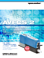
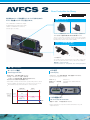
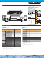
AVFCS 2
Flow Controller for Slurry
小型、軽量化 した New モデル誕生!!
完全ストレートな流路構造をもつスラリー用流量コントローラー!
New design with more compact body,
lightweight model release
Slurry flow controller with a straight
passage structure
小型、軽量化!
∼従来品の約30%削減∼
パージレス! LCD 表示!
Compact、Lightweight !
~30% reduction compare to conventional ∼
Non-Purge ! LCD display !
AVFCS 2
当社独自のストレート型流量計とピンチバルブを組み合わせた
スラリー用流量コントローラを小型化しました。
Flow Controller for Slurry
電動ピンチバルブ
Electric pinch valve
The combination of AVFCS's unique
straight flow meter and a pinch valve
enables a suitable flow control for
various types of slurry.
ストレートな流路構造であるピンチバルブを利用した調節弁です。
スラリー液に対して豊富な実績と優れた耐久性を兼ね備えています。
This is a control valve consisting of a pinch valve with a straight
passage structure. This system is based on various past experience
involving slurry solutions and excellent durability.
ストレート型超音波流量計
Straight ultrasound flow meter
ストレートな流路構造により、スラリー液や気泡の内部残留を抑制する
ことが可能です。
The straight passage structure makes it possible to reduce the
amount of any internal residue of slurry solutions and air bubbles.
Acquired patent
【取得特許/ 】
(Patent No.4233445JP / US・China patented / Korea・Taiwan patent pending)
機 能
Functions
オートパージ機能
LCD 表示
Auto Purge Function
LCD Display
・リアルタイムに、エラー情報や動作状態、現在流量値がモニタできます。
・気泡混入時は、下図の動作を自動で行います。
*Purge : バルブポジション全開(下図の例)
・operating state displays in real time
その他にバルブ開度指定位置、開度保持が選択できます。
・気泡が流れ出ると直後より制御を開始します。
・When bubble is mixed, automated valve operation will preform as below.
*Purge : Full Open, Specified position or position keep can be choose.
「EF0 xxx. x 」 気泡混入エラー / 現在流量
(mL/min)
「EF0 xxx. x 」
Operating state / Current flow rate
(mL/min)
*When bubble is purge, CLC would back to normal operation.
開度保持時間
Opening retention time
全開時間
Full open time
Purge *
バルブポジジョン
Valve position
流量表示
Flow display
Control
Hold
一定値
Constant valve
一定値
Constant valve
ゼロ
Zero
気泡混入 Bubbly
アラーム発令
Alarm Out
リゼロ調整ボタン
Re-zero adjustment button
・調整ボタンを設け、ゼロ流量の補正ができます。 ・Improved maintenance is provided outside the flowmeter zero point
adjustment button
寸 法
Size
(単位:mm)
(Unit:mm)
内部回路と接続例 (4-20mA 仕様)
Internal circuit and example of
connections (4-20mA)
24VDC +
227
211.5
7
24VDC −
50
30
FlareType
6.35×4.35mm
108.5
Re-Zero Signal
9
4-20mA +
10
0ー5/0ー10V +
11
R
設定流量
コモン Common −
12
Alarm +
アラーム 4
Alarm −
アラーム Port B
(OUT)
FlareType
6.35×4.35mm
3
4-20mA −
5
0ー5/0ー10V +
6
0ー5/0ー10V −
7
流量出力
7
(250)
+
送信機器
Transmission device
+
−
送信機器
Transmission device
1
4-20mA +
19
19
59.5
Port A
(IN)
8
Re-Zero信号
2.2kΩ
Designed flow rate
DC24V
+
2
Flow rate output
DC24V
+
受信機器
Receiving device
+
受信機器
Receiving device
AVFCS 2内部回路 AVFCS 2 internal circuit
仕 様
Specifications
一般仕様
性能
General specifications
Performance
項 目
単 位
仕 様
項 目
単 位
仕 様
Category
Unit
Specifications
Category
Unit
Specifications
流 体 温 度
℃
Fluid temperature
構 造 耐 圧*1
Pressure resistance of the structure*1
使用圧力範囲*1
Range of differential pressures*1
使用差圧範囲
Range of operation pressures
使用環境
MPa
1.0
MPa
0.1 ∼ 0.3
MPa
0.1 ∼ 0.3
周 囲 温 度
Operating
environment
15 ∼ 35
℃
20 ∼ 30
Operating humidity
%
30 ∼ 80
(結露なき事)
開 閉 頻 度
回/min
< 10
ー
制限有り*2
ー
PFA/PTFE/シリコンベースラバー
Ambient temperature
使 用 湿 度
Frequency of opening/closing
30– 80(No condensation)
times/min
取 付 姿 勢
Position of installation
接液部 材質
Material of wetted parts
接 続
Limited*2
PFA /PTFE / Silicone base rubber
ー
Flare Type, Super 300 P
mm
6.35 × 4.35
mm
1.6
源
ー
24VDC±10%
消 費 電 流
A
≦ 0.4
Connection
流入出口
接 続 口 径
Connection tube size
Outlet of the flow
オ リ フィス
Orifice diameter
電 Power
Current consumption
重 Weight
量
kg
0.9
*1:液体温度と使用圧力範囲の関係は継手メーカーの仕様を参照ください。
*2:別紙「取扱説明書」をご覧ください。
*1:Please refer to specifications of a fitting manufacturer for the relationship between fluid
temperature and the range of operating pressure.
*2:Please refer to the attached Instruction Manual.
流 量 範 囲
Flow range
流 量 精 度*1
Flow rate precision*1
再 現 性
*1
Precision of
repeated operation*1
応 答 時 間
ー
ー
Sec
閉 止 時 間
秒
Shutdown time
Sec
弁座 漏れ量
ー
C
ー
v
値*2
Cv value *2
50 ∼ 500
1%R.D.(>50mL/min)
0.75mL/min(≦50mL/min)
0.5%R.D.(>50mL/min)
0.5mL/min(≦50mL/min)
秒
Response time
Leak at valve seat
25 ∼ 250
mL/min
≦ 1(Typical)
≦ 1(Typical)
0 ㎤/min(水圧, 23℃)
0 ㎤ / min(at hydraulic pressure, 23℃ )
*1:純水・水温 25℃ における性能です。
それ以外の温度についてはお問い合わせください。
*2:全開時の値です。
*1:The performance was tested with DIW at 25℃.
For other temperature, please contact with AOC.
*2:Value when a valve is fully open.
0.05
型式選定
AVFCS 2
Selection of a model
ー
A
流量範囲
Flow rate range
0
2
5
0
N
0
2
5
0
25ー250mL/min
0
5
0
0
50ー500mL/min
耐薬品仕様
N
Chemical resistant specifications
F
Ⅰ
標準仕様*1
F
継手種類
規格
0
0
0
0
0
Standard specifications *1
Flare Type 1/4 フィッティング Flare Type 1/4” Fitting
Super 300P 1/4 フィッティング Super 300P 1/4” Fitting
3
Fitting type
ー
Ⅰ
インチ
inch
M
ミリ
millimeter
Standard
特殊品コード
*2
0
Special product code*2
0
0
0
0
*1:標準仕様は次の材質で構成されています。接液材質:シリコンベースラバー、
PFA、
PTFE/その他シール材:EPDM
*2:特殊品コードは別紙「取り扱い説明書」
に記載された場合に使用するもので、
弊社からご連絡いたします。
*1:The standard specifications consist of the following materials: Materials which come in contact with fluid: Silicon base rubber, PFA, PTFE / Other sealing material: EPDM
*2:Special product codes are used when they are listed in the attached Instruction Manual, and this will be announced by Asahi Organic Chemicals Industry.
構成部品
Component parts
本体
専用信号ケーブル
Main unit
Specialized special signal cable
OPTION:AVFCS2-CBL0-00000
LCD
リゼロ調整ボタン
長さ5m
Re-zero button
流出口
Outflow gate
Length: 5 m
通信コネクタ
(使用禁止)
Communication connector
(not use)
信号コネクタ
(ダストキャップ付)
Signal connector
(with a dust cap)
流入口
信号コネクタへの配線用ケーブルです。
Inflow gate
Signal connector cable
※本カタログの内容は製品改良のため、予告なく変更する場合がございます。
※The contents of this catalog are subject to change without prior notice for product improvement.
管材システム事業部 ダイマトリックス・装置・システム部
Valve & Piping Systems Administration,
Dymatrix Business Promotion Department
大阪営業所
Osaka Office
福岡営業所
Fukuoka Office
Head Office / Overseas Department
2013年11月第1版 AV-F-026-J
〒105-6120 東京都港区浜松町2丁目4番1号 世界貿易センタービル20階
TEL:03-3578-6016 FAX:03-3578-6025
20th Floor, World Trade Center Bldg., 4-1 Hamamatsu-cho 2 chome,
Minato-Ku, Tokyo 105-6120, Japan
Tel: +81-3-3578-6016, Fax: +81-3-3578-6025
〒541-0048 大阪市中央区瓦町4丁目5番9号 井門瓦町ビル7F
TEL:06-4707-1080 FAX:06-4707-1088
7th Floor, 5-9 Kawaramachi 4 chome, Chuo-ku, Osaka 541-0048, Japan
Tel: +81-6-4707-1080, Fax: +81-6-4707-1088
〒812-0016 福岡市博多区博多駅南1-8-13 博多駅南Rビル8F
TEL:092-413-8700 FAX:092-413-8722
8th Floor, Hakataeki Minami R Bldg., 1-8-13 Hakataeki Minami,
Hakata-ku, Fukuoka 812-0016, Japan
Tel: +81-92-413-8700, Fax: +81-92-413-8722
World Trade Center Bldg., 20F, 4-1 Hamamatsu-cho 2 chome,
Minato-ku, Tokyo 105-6120, Japan
Tel:+81-3-3578-6016 FAX:+81-3-3578-6025
ISO9001
管材システム事業部はISO9001: 2008の品質マネジ
メントシステムの認証を取得しています。
Valve & Piping Systems Administration has been
certified for the ISO9001:2008 Quality Management
Systems.
ISO14001
延岡本社・延岡製造所・エンジニアリング部・物流業務
課(延岡物流センター含む)
・愛知工場・栃木工場・広
島工場はISO14001:2004の環境マネジメントシステ
ムの認証を取得しています。
Nobeoka Head Office, Nobeoka Plant, Engineering
Division, Distribution Department (including
Nobeoka Distribution Center), Aichi Plant, Tochigi
Plant, and Hiroshima Plant have been certified for
the ISO14001:2004 Environmental Management
Systems.
旭有機材ホームページ
Website of Asahi Organic Chemicals Industry
http://www.asahi-yukizai.co.jp
2013年11月初版

![取扱説明書 [PDF形式]](http://vs1.manualzilla.com/store/data/006720402_3-7cd15b045489a1486446929fe5a40037-150x150.png)
