1
HM- 9097 - 8
ワールドKシリーズ
オリエンタルモーターの製品をご購入いただき、ありがとうございます。
ご使用の前に、必ず取扱説明書を熟読し、製品の知識、安全の情報
そして注意事項のすべてについて習熟してからご使用ください。
お読みになった後は、いつでも使用できるように必ず所定の場所に
保管してください。
無励磁作動型 電磁ブレーキ付モーター
取扱説明書
C
〈目次〉 1.安全上の留意点…………………………P.1
5.時間定格について………………………………P.5
6.拘束時の焼損保護について……………………P.5
7.正常に動作しない場合のチェックポイント…P.6
2.現品到着時の確認………………………P.2
3.取り付け…………………………………P.2
4.接続および運転…………………………P.4
1. 安全上の留意点
この取扱説明書では、安全注意事項のランクを「警告」「注意」として区分してあります。
なお、
警告
:取扱いを誤った場合に、危険な状況が起こりえて、死亡または重傷を受ける可能性が想定される場合
注意
:取扱いを誤った場合に、危険な状況が起こりえて、中程度の傷害や軽傷を受ける可能性が想定される場合
注意
および物的損害のみの発生が想定される場合
に記載した事項でも、状況によっては重大な結果に結びつく可能性があります。
いずれも重要な内容を記載していますので必ず守ってください。
守らなかった場合は、感電、けが、やけど、火災、装置破損の恐れがあります。
警告
【全般】 ●爆発性雰囲気、引火性ガスの雰囲気、腐食性の雰囲気、水のかかる場所、可燃物のそばでは使用しないでください。
●通電状態で移動、取り付け、接続、点検の作業をしないでください。電源を切ってから作業してください。
●取り付け、接続、点検の作業は、専門知識のある人が実施してください。
【取り付け】●モーターはクラス Σ機器のみに使用してください。
【接続】 ●接続は結線図に基づき確実に行なってください。
●リード線(ケーブル)を無理に曲げたり、引っ張ったり、はさみ込んだりしないでください。
●モーターを機器に取り付ける場合は、手が触れないようにするか、接地してください。
【運転】 ●活電部が露出した状態で運転はしないでください。
●停電した時や過熱保護装置(サーマルプロテクタ)が働いた時は、電源を切ってください。
●電磁ブレーキは確実に負荷を固定するものではありません。
また、過熱保護装置(サーマルプロテクタ)が働いた場合は、負荷は保持されません。
安全ブレーキとしてご使用される場合は、別系統の安全対策を設けてください。
注意
【全般】 ●モーターの仕様を超えて使用しないでください。
●濡れた手で操作しないでください。
【開梱】 ●現品が注文通りのものかどうか、確認してください。
【運搬】 ●運搬時はモーター出力軸、リード線(ケーブル)を持たないでください。
【取り付け】●モーターは確実に固定してから運転してください。
●回転部分に触れないようカバー等を設けてください。
●機械との結合前に回転方向を確認してください。
●モーターには乗ったり、ぶらさがったりしないでください。
●モーター出力軸(歯切り部)は、素手でさわらないでください。
●モーターとギヤヘッドを組み付ける際または、装置にモーターを組み付ける際は、
そのすきまに手をはさまないようにしてください。
【運転】 ●機械と結合し運転を始める場合は、いつでも非常停止できる状態にしてから行なってください。
●異常が発生した場合は直ちに電源を切ってください。
●モーターは通常の運転状態において、表面温度が70℃を超える場合があります。
運転中、そのモーターに接近できる場合には、右図の警告ラベルをはっきり見えるように
貼ってください。
●長時間拘束されたモーターにはさわらないでください。
●運転中、回転体(出力軸)へは接触しないでください。
【点検】 ●運転中、停止直後はモーターに手や体を触れないでください。
【その他】●修理、分解、改造は、行なわないでください。
●モーターを廃棄する場合は、産業廃棄物として処理してください。
警告ラベル
1
2. 現品到着時の確認
2. 1
現品の確認
以下のものがすべて揃っているか確認してください。
もし、不足している場合や破損している場合は、最寄りの支店・営業所にご連絡ください。
・モーター……………………1台
・コンデンサ…………………1個 (単相モーターのみ)
・コンデンサキャップ…………1個 (単相モーターのみ) ・取扱説明書(本書)…………1部
2. 2
品名の確認
製品がお手元に届きましたら、銘板を見てモーターとコンデンサの組み合わせをお確かめください。
モーターの品名、電圧、出力、コンデンサ容量は、銘板記載事項を見て確認してください。
■100V/110V/115Vタイプ
品名 ※
モーター品名 ※
2RK6GN-AWMJ
2RK6GN-AWMU
3RK15GN-AWMJ
3RK15GN-AWMU
4RK25GN-AWMJ
4RK25GN-AWMU
5RK40GN-AWMJ
5RK40GN-AWMU
5RK60GU-AWMJ
5RK60GU-AWMU
5RK90GU-AWMJ
5RK90GU-AWMU
2RK6GN-AWM
2RK6GN-AWM
3RK15GN-AWM
3RK15GN-AWM
4RK25GN-AWM
4RK25GN-AWM
5RK40GN-AWM
5RK40GN-AWM
5RK60GU-AWM
5RK60GU-AWM
5RK90GU-AWM
5RK90GU-AWM
■200V/220V/230Vタイプ
品名※
コンデンサ品名
2RK6GN-CWMJ
2RK6GN-CWME
3RK15GN-CWMJ
3RK15GN-CWME
4RK25GN-CWMJ
4RK25GN-CWME
5RK40GN-CWMJ
5RK40GN-CWME
5RK60GU-CWMJ
5RK60GU-CWME
5RK90GU-CWMJ
5RK90GU-CWME
2IK6GN-SWM
4IK25GN-SWM
5IK40GN-SWM
5IK60GU-SWM
5IK90GU-SWM
CH45FAUL
CH35FAUL
CH75CFAUL
CH60CFAUL
CH100CFAUL
CH80CFAUL
CH160CFAUL
CH120CFAUL
CH250CFAUL
CH200CFAUL
CH350CFAUL
CH300CFAUL
モーター品名※
2RK6GN-CWM
2RK6GN-CWM
3RK15GN-CWM
3RK15GN-CWM
4RK25GN-CWM
4RK25GN-CWM
5RK40GN-CWM
5RK40GN-CWM
5RK60GU-CWM
5RK60GU-CWM
5RK90GU-CWM
5RK90GU-CWM
2IK6GN-SWM
4IK25GN-SWM
5IK40GN-SWM
5IK60GU-SWM
5IK90GU-SWM
コンデンサ品名
CH10BFAUL
CH08BFAUL
CH18BFAUL
CH15BFAUL
CH25BFAUL
CH20BFAUL
CH40BFAUL
CH35BFAUL
CH60BFAUL
CH50BFAUL
CH80BFAUL
CH70BFAUL
※ 品名(モーター品名)は歯切りシャフトタイプです。
丸シャフトタイプの場合は、品名(モーター品名)の「GN」「GU」の部分が「A」になります。
モーターは下記の規格にしたがって設計・検査を行なっており、認定を取得しています。認定品名は、モーター品名です。
このモーター (5IK90GU-SWM, 5IK90A-SWMを除く) はVDE認定を取得しています。VDE認定は、モーター単体での認定となります。
単相モーターは、付属コンデンサとモーターの組み合わせでEN60950 Annex B. 8 項の試験に合格しています。
5IK90GU-SWM, 5IK90A-SWMはDEMKOの認定を取得しています。
・認定規格
・適合規格
UL2111、UL1004、CSA C22.2 No. 100、CSA C22.2 No. 77、EN60950-1
認証機関
モーター:UL FileNo. E64199 (6Wタイプ)、E64197 (15W∼90Wタイプ)
VDE
DEMKO
コンデンサ:UL FileNo. E83671 (CYWT2)、VDE LicenceNo. 114747 (コンデンサ定格電圧450VACタイプのみ)
コンデンサキャップ:UL FileNo. E56078 (YDTU2)
EN60034-1、EN60034-5、IEC60034-11、IEC60664-1
上記規格で要求される過負荷運転試験および拘束温度上昇試験は、歯切シャフトタイプはギヤヘッド付、
丸シャフトタイプは放熱板付の状態で行なっています。放熱板のサイズ、材質は以下の通りです。
モーター品名の頭文字
・設置条件
サイズ (mm) 厚さ(mm)
2
115×115
3
125×125
4
135×135
5 (40W)
165×165
5 (60W, 90W)
200×200
5
材質
アルミ
過電圧カテゴリーΤ、汚染度2、クラスΣ機器 (適用規格 EN/IEC規格)
機器によって過電圧カテゴリー Υ、汚染度3の規定値が要求される場合は、モーターをIP54相当のキャビネットに収納し、
絶縁トランスを介してモーターには定格電圧を給電してください。
3. 取り付け
取付条件 モーター、コンデンサは以下の条件のところに取り付けてください。
2
この範囲外で使用すると製品が破損する恐れがあります。
・屋内(この製品は機器組込用に設計、製造されたものです)
・周囲温度 −10℃∼+40℃(凍結しないこと)
ただし、100V/200V運転時は−10℃∼+50℃
・周囲湿度 85%以下(結露しないこと)
・爆発性ガス、引火性ガス、腐食性ガスがないこと
・直射日光が当たらないこと
・ほこりがかからないこと
・水、油などがかからないこと
・放熱しやすいこと
・連続的な振動、過度の衝撃が加わらないこと
・標高1,000m以下
・過電圧カテゴリーΤ 、汚染度2、クラスΣ 機器(適用規格 EN/IEC規格)
機器によって過電圧カテゴリーΥ 、汚染度3の規定値が要求される
場合は、モーターをIP54相当のキャビネットに収納し、
絶縁トランスを介してモーターには定格電圧を給電してください。
3. 1モーターの取り付け
モーター出力軸の形状によって取り付けが異なります。
1)丸シャフトタイプ
取付板に穴をあけ、ねじ、ナット、座金を使用し、モーターを
取付板に固定してください。(取付用のねじは付属していません。)
この時、モーター取付面と取付板にすきまがないようにしてください。
モーター
取付板
取付用ねじ
注記
取付ねじ
モーター品名の頭文字
サイズ
締付トルク
2
M4
2.0N·m (20kgfcm)
3
M5
2.5N·m (25kgfcm)
4
M5
2.5N·m (25kgfcm)
5
M6
3.0N·m (30kgfcm)
取付穴にモーターを斜めに挿入したり、
無理に組み付けたりしないでください。
フランジインロー部に傷が付き、
モーターが破損する恐れがあります。
2)歯切シャフトタイプ
取付板に穴をあけ、別売のギヤヘッド付属のねじ4本を使用し、
モーターとギヤヘッドを 取付面に固定してください。
この時、モーターフランジ面とギヤヘッドインロー端面に
すきまがないように取り付けてください。
取り付けの詳細については、別売のギヤヘッドの取扱説明書を
参照してください。
モーター
ギヤヘッド
取付板
ギヤヘッド付属のねじ
注記
ギヤヘッドはモーターと同じ歯切りタイプのものを使用してください。
3)冷却ファン付モーター
冷却ファン付モーターを装置に取り付ける場合には、モーター後部の冷却吸込口をふさがないように、
ファンカバーの後ろを10mm以上あけるか、換気穴をあけてください。
3. 2
コンデンサの取り付け(単相モーターのみ)
付属のコンデンサの容量が、モーター銘板に記載されている容量と合っているかどうか確認してから
コンデンサの取り付けを行なってください。
コンデンサの取り付けには、M4のねじを使用してください。(取付用のねじは付属していません。)
注記
・ねじの締付トルクは、取付足の破損防止のため、1N·m(10kgfcm)以下としてください。
・モーターから10cm以上離して取り付けてください。
φ4.3
3. 3
モーターの熱によりコンデンサの寿命が短くなります。
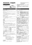
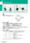
ケーブルの向きを変える方法(60W, 90Wタイプの場合)
60W、90Wタイプの場合、ケーブル引き出し口は出荷時モーター出力軸方向に向いています。
引き出し口は180゚向きを変えることができます。
向きを変える場合は、以下のように行なってください。
㽲 ケーブルクランプのねじとケーブルクランプ上部を外し、
①
M3六角穴付ねじ
ケーブルを反対側に倒してください。
ケーブルクランプ
ケーブル
㽳 ケーブルクランプを180゚回転させてください。
②
㽴 ケーブルクランプ上部を取り付け、ねじで留めてください。
③
注記
ねじの締め付けは、ケーブルがゆるんだり、
破損しないよう以下の締付トルクを参考に行なってください。
ねじ締付トルク 0.5N·m (5kgfcm) ∼ 0.7N·m (7kgfcm)
3
4. 接続および運転
4. 1
接続
・モーターは「結線図」にしたがって接続してください。
・モーターリード線と電源接続部、コンデンサ端子接続部などのすべての接続部は絶縁処理をしてください。
コンデンサ端子接続部の絶縁処理用には、付属のコンデンサキャップを使用してください。
3
コンデンサキャップ取付順序
1
㽲 コンデンサキャップにリード線を通してください。
㽳 端子にリード線を接続してください。
コンデンサキャップ
㽴 コンデンサキャップを被せてください。
2
コンデンサ
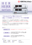
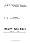
■結線図
回転方向はモーター出力軸側から見た場合です。時計方向をCW、反時計方向をCCWとしています。
単相モーター
三相モーター
CCW
Ro
赤
Co
Ro
モーター
黒
ON
ON
SW1
CW
三相電源
(U)
R
(V)
S
(W)
T
白
SW2 CCW
CW
電源
CW
Ro
Co
赤
白
Ro
Co
橙
モーター
橙
SW1
電磁ブレーキ
橙
Co
黒
コンデンサ
Ro
橙
電磁ブレーキ
Co
[ 6 ∼ 25Wタイプ ]
スイッチの接点容量
単相100V/110V/ 単相200V/220V/ 三相200V/220V/
備考
115V入力
230V入力
230V入力
AC250V 1.5A以上 連動のこと
AC125V
AC250V
−
3A以上
1.5A以上
−
スイッチの
番号
SW1
SW2
SW1
SW2
200WV
オプション品名 EPCR1201-2(別売)
スイッチの接点容量
単相100V/110V/ 単相200V/220V/ 三相200V/220V/
115V入力
230V入力
230V入力
AC250V 5A以上
AC125V
AC250V
番号
Ro=5∼200Ω
Co=0.1∼0.2μF
)を
当社でもオプションとしてご用意しております。
[ 40 ∼ 90Wタイプ ]
スイッチの
接点保護として結線図のように
サージ電圧吸収用CR回路(
接続してください。
5A以上
−
5A以上
備考
連動のこと
−
注記
60W、90Wタイプの場合、
ケーブルの外部シースを剥く時には、
中のリード線を傷つけないように
してください。
■コンデンサの接続(単相モーターのみ)
C
A
187シリーズ タブ
コンデンサ内部の結線は左図のようになります。
コンデンサの端子は電気的には2端子で、AとB、CとDは内部で接続しています。
結線の簡単な圧着端子を使用する場合は、以下の端子をお使いください。
Tyco Electronics AMP
アンプ・ファストン・ターミナル 187シリーズ
リード線との接続は、1個の端子に1本のリード線としてください。
D
B
■結線の簡略化
CCW
SW2 CCW
CW
電源
Ro
Co
白
赤
黒
SW1 ON
橙
Ro
橙
Co
コンデンサ
4
CW
モーター
電磁ブレーキ
注記
上下駆動運転および三相モーターの場合は、結線を簡略化できません。
モーターの運転/停止と電磁ブレーキの運転/停止を1つのスイッチで
行ないたい場合には、左図のように結線を簡略化することもできます。
ただし、その場合には基本結線図の時に比べて、制動時間が約50msec.
長くなり、そのぶんオーバーランも増えます。
これはSW1をOFFにしても、モーターの磁気エネルギーが
電磁ブレーキの励磁巻線に作用し、約50msec.の間電磁石が作用し続け、
ブレーキがかかるのが遅れるためです。
4. 2
運転
注記 ・このモーターは、B種絶縁モーターです。
モーター運転中は、モーターケースの温度が90℃を超えないことを確認してください。
90℃を超える温度でモーターを運転すると、巻線、ボールベアリングが著しく劣化し、寿命が短くなります。
モーターケースの温度は、モーター表面に温度計を固定して計測できます。
また、サーモテープまたは熱電対を使用しても計測できます。
・単相モーターは付属のコンデンサを使用し、モーターが起動した後もコンデンサは常時接続しておいてください。
[SW1とSW2のタイミングチャート例]
このタイミングチャート例は、基本結線図の場合です。
停止
保持
運転
停止
保持
運転
CCW
SW2
CW
SW1
OFF
OFF
ON
モーター
OFF
ON
CW
CW
CCW
■運転 / 停止
SW1はモーター運転/停止と電磁ブレーキ操作用です。(連動)
SW1をONにすると電磁ブレーキが解除され、モーターが回転します。SW1をOFFにすると電磁ブレーキが作動し、モーターは停止します。
注記
電磁ブレーキが作動すると、ブレーキは摩擦式のため摩擦音がする場合ありますが、異常ではありません。
■回転方向の切り替え
[ 単相モーター ] SW2をCW側に倒すと時計方向に回転し、CCW側に倒すと反時計方向に回転します。
[ 三相モーター ] 結線図のように接続すると時計方向に回転します。U,V,Wのうち、いずれか2線を入れ替えると反時計方向に回転します。
■その他の操作方法
注記
上下駆動に使用する場合は、負荷が下降する場合がありますので、負荷の状況をご確認の上操作してください。
・モーターの立上り時間を速くする方法
あらかじめ、電磁ブレーキを開放しておけば、さらに速くモーターを立ち上げることができます。
電磁ブレーキを開放するタイミングはモーターを立ち上げる10msec以上前に行なってください。
・モーター停止時に電磁ブレーキを開放する方法
2本の電磁ブレーキ用リード線(橙)間に通電すれば、電磁ブレーキは解除され、モーター軸は自由に回すことができます。
5. 時間定格について
インダクションモーターは連続運転が可能です。(連続定格)
レバーシブルモーターは連続運転可能時間が30分となっています(30分定格 : 銘板に「30min」と記載されています) 。
6. 拘束時の焼損保護について
このモーターは、モーターが何らかの原因で異常発熱し、焼損に至るのを防止するための機能を備えています。
保護方式には次の2通りがあります。
■サーマルプロテクタ方式(銘板に「TP」
「TP211」と記載されています)
このモーターは、自動復帰型のサーマルプロテクタをモーター巻線部に内蔵しています。モーター内部の温度が規定値以上になると、サーマル
プロテクタがはたらいてモーターは停止します。
このとき、電磁ブレーキは解放されたままになっているため、負荷を保持しません。別系統の安全対策を設けてください。
点検作業は必ず電源を切ってから行なってください。
サーマルプロテクタ動作温度
開(電源を遮断する)………130℃±5℃
閉(電源をつなげる)……… 82℃±15℃
■インピーダンスプロテクト方式(銘板に「ZP」と記載されています)
異常時に拘束状態になった場合、巻線インピーダンスが大きくなり、モーターへの入力を抑制し、モーター巻線が焼損に至らないように
なっています。
5
7. 正常に動作しない場合のチェックポイント
モーターが正常に動作しないときは、下の表にしたがって点検してください。
点検の結果、すべて正常であるにもかかわらずモーターが正常に動作しない場合は、修理・分解・改造は行なわず、
お客様ご相談センター、または最寄りの支店・営業所にご連絡ください。
確認内容
現 象
モーターが回転しない
または、低速で回転する
モーターが回転したり、
しなかったりする
逆方向に回転する
①モーターに正規の電圧が加えられていますか?
②電源との接続は確実ですか?
③負荷が大きすぎませんか?
④端子台や圧着端子を使用して延長している場合、接続不良になっていませんか?
⑤単相モーターの場合、付属のコンデンサまたは、銘板に記載されている容量の
コンデンサがP.4の「結線図」通りに接続されていますか?
⑥電磁ブレーキ用リード線 (橙) に正規の電圧が加えられていますか?
①電源との接続は確実ですか?
②端子台や圧着端子を使用している場合、接続不良になっていませんか?
③単相モーターの場合、付属のコンデンサまたは、銘板に記載されている容量の
コンデンサがP.4の「結線図」通りに接続されていますか?
①「結線図」と違う接続をしていませんか?
P.4の「結線図」をもう一度見てください。
②ギヤヘッドの減速比によっては、ギヤヘッド出力軸の回転方向が異なります。
ギヤヘッドの取扱説明書を参照してください。
③単相モーターの場合、付属のコンデンサまたは、銘板に記載されている容量の
コンデンサがP.4の「結線図」通りに接続されていますか?
④見る方向が違っていませんか?
モーター出力軸側から見て回転方向を時計方向、反時計方向としています。
①モーターに正規の電圧が加えられていますか?
②周囲温度範囲の上限を超えていませんか?
(モーターケース温度が90℃を超えている) ③単相モーターの場合、付属のコンデンサまたは、銘板に記載されている容量の
コンデンサがP.4の「結線図」通りに接続されていますか?
モーターが異常に熱くなる
異音がする
①モーターとギヤヘッドを正しく組み付けていますか?
ギヤヘッドの取扱説明書を参照してください。
②モーターと同じ歯切りタイプのギヤヘッドを組み付けていますか?
・この取扱説明書の一部または全部を無断で転載、複製することは、禁止されています。
損傷や紛失などにより、取扱説明書が必要なときは、最寄りの支店または営業所に請求してください。
・取扱説明書に記載されている情報、回路、機器、および装置の利用に関して産業財産権上の問題が生じても、当社は一切の責
任を負いません。
・製品の性能、仕様および外観は改良のため予告なく変更することがありますのでご了承ください。
・取扱説明書には正確な情報を記載するよう努めていますが、万一ご不審な点や誤り、記載もれなどにお気づきの点がありまし
たら、最寄りのお客様ご相談センターまでご連絡ください。
・
は、オリエンタルモーター株式会社の商標です。
その他の製品名、会社名は各社の商標または登録商標です。この取扱説明書に記載の他社製品名は推奨を目的としたもので、
それらの製品の性能を保証するものではありません。オリエンタルモーター株式会社は、他社製品の性能につきましては一切
の責任を負いません。
© Copyright ORIENTAL MOTOR CO., LTD. 2008
http://www.orientalmotor.co.jp/
䃂㩷ຠ䈮䈧䈇䈩䈱䈗⾰䇮䈗⋧⺣䈲䈍ቴ᭽䈗⋧⺣䉶䊮䉺䊷䈻䈍䈇ว䉒䈞䈒䈣䈘䈇䇯
㩷 䊐䊥䊷䉮䊷䊦㩿ήᢱ㪀䈪䈜䇯៤Ꮺ㔚䊶PHS䈎䉌䉅䈗↪䈏น⢻䈪䈜䇯
㩷 ฃઃᤨ㑆㩷
㩷 㩷
᧲㩷 ੩㩷
ฬฎ㩷ደ㩷
ᄢ㩷 㒋㩷
ᐔᣣ㩷
9:00䌾18:30
ᦐᣣ㩷 9:00䌾17:30
TEL 0120-925-410 FAX 0120-925-601
TEL 0120-925-420 FAX 0120-925-602
TEL 0120-925-430 FAX 0120-925-603
䈖䈱ขᛒ⺑ᦠ䈲ౣ↢⚕䉕↪䈚䈩䈇䉁䈜䇯
6
HM-9097-8
World K Series
Thank you for purchasing ORIENTAL MOTOR products.
Please read this operating manual thoroughly before
installing and operating the motor, and always keep
the manual where it is readily accessible.
Electromagnetic Brake Motors
OPERATING MANUAL
C
<Table of contents>
1. Precautions…………………………………Page 1
2. Checking the package contents ……………Page 1
3. Installation……………………………………Page 2
4. Connection and Operation …………………Page 4
5. Time Rating…………………………………Page 5
6. Locked rotor burnout protection……………Page 5
7. Troubleshooting……………………………Page 6
1. Precautions
1. 1
Precautions for Installation
●Do not use in a place where there is flammable gas and/or corrosive gas.
●When installing the motor into your equipment, ensure that the motor lead wires are fixed and do not move.
In addition, do not apply any pressure to these lead wires.
●Motors for use only in equipment of protection class I.
Motore zur Verwendung in Geräten der Schutzklasse I.
●The motor housing must be mounted with a screw and spring washer to the ground point of the equipment.
Die Gehäuse der Motore sind mit einer Schraube und Zahnscheibe sicher mit dem geerdeten Gehäuse des Gerätes zu verbinden.
●Installation must be performed by a qualified installer.
1. 2
Precautions for Operation
●The Motor case temperature can exceed 70°C (depending on operation conditions). In case motor is
accessible during operation, please attach the following warning label so that it is clearly visible.
Warning label
●Always turn off the power to the motor before conducting checks or performing work on the motor.
Thermally protected motors will restart automatically when motor temperature falls bellow a certain level.
●The electromagnetic brake is designed to activate when power is removed. However, it may not arrest all loads completely. If this motor is
designed to hold in emergency situations then a second method of stopping the load must be used to ensure to load stops. If this is not used
injury or machine damage may result.
2. Checking the package contents
2. 1
Checking the contents
Make sure that you have received all of the items listed below.
If an accessory is missing or damaged, contact the nearest ORIENTAL MOTOR office.
-Motor..........................1
-Capacitor cap.......................1 (for only single-phase motors)
-Capacitor.....................1 (for only single-phase motors)
-This operating manual...........1
2. 2
Checking the product name and motor-capacitor combination
This product comes in a combined set consisting of a motor and a capacitor. When the product first arrives, check the name plates to confirm that
you have received the correct motor and capacitor combination.
■100V/110V/115V type
∗
Model ∗
Motor Model ∗
2RK6GN-AWMJ
2RK6GN-AWMU
3RK15GN-AWMJ
3RK15GN-AWMU
4RK25GN-AWMJ
4RK25GN-AWMU
5RK40GN-AWMJ
5RK40GN-AWMU
5RK60GU-AWMJ
5RK60GU-AWMU
5RK90GU-AWMJ
5RK90GU-AWMU
2RK6GN-AWM
2RK6GN-AWM
3RK15GN-AWM
3RK15GN-AWM
4RK25GN-AWM
4RK25GN-AWM
5RK40GN-AWM
5RK40GN-AWM
5RK60GU-AWM
5RK60GU-AWM
5RK90GU-AWM
5RK90GU-AWM
■200V/220V/230V type
Capacitor Model
CH45FAUL
CH35FAUL
CH75CFAUL
CH60CFAUL
CH100CFAUL
CH80CFAUL
CH160CFAUL
CH120CFAUL
CH250CFAUL
CH200CFAUL
CH350CFAUL
CH300CFAUL
Model ∗
2RK6GN-CWMJ
2RK6GN-CWME
3RK15GN-CWMJ
3RK15GN-CWME
4RK25GN-CWMJ
4RK25GN-CWME
5RK40GN-CWMJ
5RK40GN-CWME
5RK60GU-CWMJ
5RK60GU-CWME
5RK90GU-CWMJ
5RK90GU-CWME
2IK6GN-SWM
4IK25GN-SWM
5IK40GN-SWM
5IK60GU-SWM
5IK90GU-SWM
Motor Model ∗
2RK6GN-CWM
2RK6GN-CWM
3RK15GN-CWM
3RK15GN-CWM
4RK25GN-CWM
4RK25GN-CWM
5RK40GN-CWM
5RK40GN-CWM
5RK60GU-CWM
5RK60GU-CWM
5RK90GU-CWM
5RK90GU-CWM
2IK6GN-SWM
4IK25GN-SWM
5IK40GN-SWM
5IK60GU-SWM
5IK90GU-SWM
The list opposite shows the pinion shaft motor. Round shaft motors are indicated by A before the hyphen.
Recognized name and certified name are motor model name.
Capacitor Model
CH10BFAUL
CH08BFAUL
CH18BFAUL
CH15BFAUL
CH25BFAUL
CH20BFAUL
CH40BFAUL
CH35BFAUL
CH60BFAUL
CH50BFAUL
CH80BFAUL
CH70BFAUL
1
Motors (except for the 5IK90GU-SWM and 5IK90A-SWM) are recognized by UL and certified by VDE.
Recognized name and certified name are motor model name.
The certificate by VDE is valid only for the motor assembly itself. The capacitor is not included in the certificate.
However, both the motor assembly and capacitor combined have been tested against and have passed EN60950 Annex B.8.
5IK90GU-SWM and 5IK90A-SWM are recognized by UL and certified by DEMKO.
・Standards
UL2111, UL1004, CSA C22.2 No.100, CSA C22.2 No.77, EN60950-1
Certification Body Motor : UL File No. E64199 (6W type), E64197(15W∼90W type)
VDE
DEMKO
Capacitor : UL FileNo. E83671 (CYWT2), VDE Licence No. 114747 (for only capacitor rated voltage 450VAC types)
Capacitor cap : UL FileNo. E56078 (YDTU2)
・Applications for standard EN60034-1, EN60034-5, IEC60034-11, IEC60664-1
A Running Heating Test and a Locked-Rotor Test has been conducted with a aluminum radiation plate of size indicated
below. For the motor with a gear head, tests has been conducted with a gear head instead of the radiation plate.
size
First number in motor name
2
3
4
5 (40W)
5 (60W, 90W)
・Installation Conditions
115×115
(4.53×4.53)
125×125
(4.92×4.92)
135×135
(5.31×5.31)
165×165
(6.50×6.50)
200×200
(7.87×7.87)
thickness
material
5
(0.20)
aluminium
※ Dimensions in millimeters (inches).
Overvoltage categoryΤ, Pollution degree 2, Class Σ equipment (For EN/IEC standards)
When the machinary to which the motor is mounted requires overvoltage
and pollution degree 3
specifications, install the motor in a cabinet that comply with IP54 and connect to power supply via an isolation
transformer.
3. Installation
Installation conditions
Install the motor and capacitor in a location that meets the following conditions. Using the motor and capacitor in a location that does not satisfy
these conditions could damage it.
・Indoors (this product is designed and manufactured to be installed within another device)
・Ambient temperature:-10℃(14˚F ) ∼ +40℃(104˚F ) (avoid freezing)
( -10℃(14˚F ) ∼+50℃(122 ˚F) for 100V/200V )
・Ambient humidity: 85% max. (avoid condensation)
・Not exposed to explosive, flammable, or corrosive gas
・Not exposed to direct sunlight
・Not exposed to dust
・Not exposed to water or oil
・A place where heat can escape easily
・Not exposed to continuous vibration or excessive impact
・1,000 meters or less above sea level
・Overvoltage category Τ, Pollution degree 2, Class Σ equipment (For EN/IEC standards)
When the machinary to which the motor is mounted requires overvoltage category Υ and pollution degree 3 specifications,install the motor in
a cabinet that comply with IP54 and connect to power supply via an isolation transformer.
3.1
Mounting the motor
Installation varies with the shape of the motor’s output shaft.
1) Round shaft motors
Motor
Mounting
Plate
Mounting Screws
(not provided)
Note: Do not insert the motor into the mounting hole
at an angle or force it in, as this could scratch
the flange and damage the motor.
2
Drill holes in the mounting plate that match the screws and the motor’s dimensions.
Use screws, washers, and nuts listed below to fasten the motor to the mounting
plate. Make sure that no gaps are left between the motor and the surface of the
mounting plate.
Use screws of an appropriate length.
Mounting screws
First number in motor name
Screw size
Tightening torque
2
M4
2.0N·m (20kgfcm)
3
M5
2.5N·m (25kgfcm)
4
M5
2.5N·m (25kgfcm)
5
M6
3.0N·m (30kgfcm)
2) Pinion shaft motor
Motor
Gearhead
Mounting
Plate
Screws provided
with gearhead
Drill holes in the mounting plate that match the screws and the motor’s
dimensions.
Attach the motor and gearhead using the screws supplied with the gearhead
(gearhead sold separately).
Fasten the screws supplied with the gearhead to the mounting plate. Attach so
that no gaps are left between the motor flange surface and the gearhead pilot
section end surface.
Refer to the gearhead operation manual for further details concerning mounting
(gearhead sold separately).
Note: Use the gearhead of the same type of pinion shaft as the motor.
3) Motor with cooling fan
When mounting a motor with a cooling fan onto a device, open a ventilation hole or leave 10 millimeters (0.4 inches) or more behind the fan cover
so that the cooling inlet on the back of the motor cover is not blocked.
3. 2
Mounting the capacitor (For only single-phase motors)
Before mounting the provided capacitor, check that the capacitor’s capacitance matches that stated on the
motor’s name plate.
Use M4 screws to mount the capacitor (screws not provided).
Note -Do not let the screw fastening torque exceed 1 N·m (10 kgfcm) to prevent damage to the mounting feet.
-Mount capacitor at least 10 cm (3.94 inches) away from the motor. If it is located closer, the life of the
capacitor will be shortened.
4.3
(.169DIA.)
3. 3
∗ Dimensions in millimeters (inches).
Changing Direction of the Cable Outlet
In case of 60W and 90W type, the direction of the cable outlet is the output shaft side of the motor when shipping.
The direction of outlet can be changed by 180° if desired.
Change the direction of the cable outlet according to following steps.
1
M3 hexagonal
socket-head screw
1. Remove screws and upper unit of cable clamp.
Put the cable toward the opposite direction.
Cable clamp
Cable
2
2. Turn the cable clamp to change the direction of cable outlet.
3
3. Refasten upper unit of cable clamp with screws.
Note:
Keep the tightening torque within the limits shown below to prevent
the cable from coming loose or to damage caused by excessive
tightening torque.
Screw tightening torque 0.5 N·m (5 kgfcm) ~ 0.7 N·m (7 kgfcm)
3
4. Connection and Operation
4. 1
Connection
・Connect the motor according to the “wiring diagram” shown below.
・Insulate all the wire connections, such as the connection between the motor and the capacitor connection.
Capacitor cap are available to insulate capacitor connection.
3
1
Capacitor caps
1.Pass the lead wires through the capacitor cover as shown in the figure.
2.Connect the lead wires to the terminals or use terminal ends.
3.Cap the capacitor with the capacitor cover.
Capacitor cap
2
Capacitor
■ Wiring diagram
The motor rotates in a clockwise (CW) and counterclockwise (CCW) direction (viewing the motor from the side with the output shaft).
Single- phase Motor
Three- phase Motor
CCW
CW
CW
Line
(U)
R
(V)
S
(W)
T
White
SW2 CCW
CW
Line
Ro
Red
Co
Orange
Ro
Co
Red
White
Motor
Ro
Co
Orange
ON
ON
SW1
Motor
Black
Ro
Co
Black
Orange
Magnetic
Brake
SW1
Capacitor
Ro
Orange
Magnetic
Brake
Co
[ 6 ∼ 25W type ]
Specification
Single-phase
Single-phase
Switch
100V/110V/115V 200V/220V/230V
No. of
AC250V
1.5A or more
AC125V
3A or more
SW1
SW2
Three-phase
Note
200V/220V/230V
AC250V 5A or more Switched Simultaneously
−
−
[ 40 ∼ 90w type ]
Specification
Single-phase
Single-phase
Switch
100V/110V/115V 200V/220V/230V
No. of
CR circuit (
) must be connected.
Ro=5∼200Ω
Co=0.1∼0.2μF 200WV
Option of the ORIENTAL MOTOR’s surge
absorber is available.
Optional product name EPCR1201-2
Three-phase
Note
200V/220V/230V
(sold separately)
AC250V 5A or more Switched Simultaneously
AC250V
AC125V
5A or more
−
5A or more
SW2
Note: In case of 60W and 90W type, When removing the sheath
of the cable, be careful not to damage the inside lead wire.
SW1
SW1 emits sparks when turned on and off.
In order to protect the relay contacts,
−
■ Capacitor Connection (For only single-phase motors)
C
A
AMP 187 series
The capacitor internal wiring is as follows:
Capacitor terminals are internally electrically connected in twos; A−B and C−D for easy connection.
For easy to install terminals use 187 series AMP FASTON Terminals.
For lead wire connection, use one lead wire for each individual terminal.
D
B
■ Simplified Connection
CCW
CW
White
SW2 CCW
CW
Line
Ro
Co
Red
Black
SW1 ON
Orange
Ro
Orange
Co
Capacitor
4
Motor
Magnetic
Brake
Note: Wiring cannot be simplified for vertical drive applications or three-phase
motors.
Connection can be simplified by using the connecting diagrams shown below
when changing the swich RUN/STOP of the motor and the electromagnetic brake
by one swich. Using the connection shown below, however, results in a 50msec.
increase in braking time over that of the basic connection with a corresponding
increase in overrun. The reason for this is that an electromagnetic energy of motor
electromagnetic brake, so that the electromagnetic continues to operate for about
50msec. even though the swich SW1 has been turned off. The brake thus takes
longer to engage.
4. 2
Operation
Note :
-This motor is B type insulation motor.
Make sure that the motor case temperature does not exceed 90°C (194°F) during motor operation.
Operating the motor above 90°C (194°F) will shorten the life of the coil and the ball bearings.
Motor case temperature can be measured by fastening a thermometer to the motor’s surface, or with thermo-tape.
-Be sure to use the capacitor that comes standard with your motor.
Keep the capacitor connected all the time even after the motor has been started.
[Timing Chart]
This Timing Chart is case of the basic connection
Brake
Run
Brake
Run
CCW
SW2
CW
SW1
OFF
OFF
ON
CW
Motor
OFF
ON
CW
CCW
■ Starting and Stopping
SW1 operates motor and electromagnetic brake action.
Motor will rotate when SW1 is switched simultaneously to ON (short circuit). When SW1 is swiched simultaneously to OFF (open),
the motor stops immediately by electromagnetic brake and holds the load.
Note : When operating the electromagnetic brake, this may make a friction noise because this is the braking system by friction,
but this is not a problem.
■ Direction of Rotation
[Single-phase motor]
To rotate the motor in a clockwise (CW) direction, swich SW2 to CW.
To rotate it in a counter-clockwise (CCW) direction, swich SW2 to CCW.
[Three-phase motor]
To change the direction of rotation, change any two connections between U, V and W.
■Other ways of operating
Note : When driving a vertical load, this method cannot be applied because this may cause the load to fall.
・Hastening the motor’s starting time
If the electromagnetic brake is left release, the motor can be started much faster.
Optimum timing for release of the brake is at least 10msec. before starting up the motor.
・Releasing Electromagnetic brake
If you wish to release the brake while the motor is stopped, apply voltage between only two orange lead wires.
The electromagnetic brake is released and the motor shaft can be rotated easily by hand.
5. Time Rating
Induction motors have a continuous rating.
Reversible motors have a 30 minutes rating. "30 min" is indicated on the nameplate.
6. Locked rotor burnout protection
This motor is equipped with one of two methods to prevent burning the motor as a result of abnormal heating.
■ Thermal protection ("TP" "TP211" is stamped on the motor name plate)
The motor has an "auto reset" type thermal protector built into its motor coil. When the motor reaches a predetermined temperature, the
internal thermal protector is activated and the motor is stopped.
In this stage, the electromagnetic brake is left released so that the motor does not keep hold of the load. Adopt another safety measure.
Always turn the power off before performing inspections.
Thermal protector activation range:
Power is turned off at 130°C (266°F) ±5°C (9°F)
Power is turned back on at 82°C (180°F) ±15°C (27°F)
■ Impedance protection ("ZP" is stamped on the motor name plate)
When the motor goes into locked rotor condition due to a malfunction, coil impedance rises, suppressing input to the motor and
protecting the motor coil from burnout.
5
7. Troubleshooting
When the motor is not functioning normally, perform an inspection covering the points listed in the table below.
If the inspection shows that everything is normal but the motor and control unit still are not functioning correctly, contact the nearest
ORIENTAL MOTOR office.
Problem
Things to check
1. Is the correct voltage being supplied to the Motor?
2. Are lead wires properly and firmly connected?
The motor does not rotate
or
motor rotates at low speed
3. Is the load too large?
4. If lead wires have been extended by using a terminal strip or terminal block, are the lead
wires properly and firmly connected at all points?
5. For a single-phase motor is the provided capacitor connected as shown in the wiring
diagram of page 4?
6. Is voltage applied to the brake lead wires?
1. Are lead wires properly and firmly connected?
The motor rotate correctly
or properly
2. If lead wires have been extended by using a terminal strip or terminal block, are the lead
wires properly and firmly connected at all points?
3. For a single-phase motor is the provided capacitor connected as shown in the wiring
diagram of page 4?
1. Is the connection as shown in the wiring diagram?
Check the wiring diagram of page 4 again.
2. The gearhead output shaft’s rotation direction differs depending on the gearhead’s
The motor rotates
in the wrong direction
deceleration ratio. Refer to the gearhead operation manual .
3. For a single-phase motor is the provided capacitor connected as shown in the wiring
diagram of page 4?
4. Are you looking at the motor from the wrong side?
Rotation is defined as viewed from the output shaftside.
The motor becomes extraordinarily
hot (motor case temperature
exceeds 90°C (194°F))
1. Is the correct voltage being supplied to the motor?
2. Does the ambient temperature exceed the permissible range?
3. For a single-phase motor is the provided capacitor connected as shown in the wiring
diagram of page 4?
1. Are the motor and gearhead correctly fastened? Refer to the gearhead operation manual.
The motor makes a strange noise
2. Is the coupled gearhead the same pinion type as the motor shaft?
• Characteristics, specifications and dimensions are subject to change without notice.
•
is a trademark of Oriental Motor Co., Ltd.
• Please contact your nearest Oriental Motor office for further information.
© Copyright ORIENTAL MOTOR CO., LTD. 2008
Technical Support Tel:(800)468-3982
8:30 A.M. to 5:00 P.M., P.S.T. (M-F)
7:30 A.M. to 5:00 P.M., C.S.T. (M-F)
E-mail: [email protected]
www.orientalmotor.com
Headquarters and Düsseldorf Office
Tel:0211-52067-00
Fax:0211-52067-099
Munich Office
Tel:089-3181225-00 Fax:089-3181225-25
Hamburg Office
Tel:040-76910443
Fax:040-76910445
Tel:(02)8228-0707
Fax:(02)8228-0708
Tel:(6745)7344
Fax:(6745)9405
Tel:(03)22875778
Fax:(03)22875528
Tel:01256-347090
Fax:01256-347099
Tel:66-2-254-6113
Fax:66-2-254-6114
Tel:01 47 86 97 50
Fax:01 47 82 45 16
KOREA
Tel:(032)822-2042~3
Fax:(032)819-8745
Tel:02-93906346
Fax:02-93906348
Headquarters Tokyo, Japan
Tel:(03)3835-0684
Fax:(03)3835-1890
Printed on Recycled Paper
6