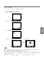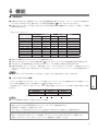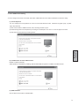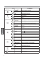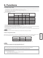
1
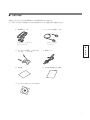
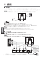
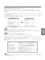
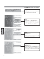
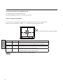
ࢼࣟࢢᢠ⭷᪉ᘧ タッチセンサ付 TFT カラー液晶モニタ 型名 TSD-AT1513-CN 取扱説明書 もくじ ページ 2. 安全のために必ず守ること ....................... 3 3. 各部の名称................................................. 6 ■ 本体正面・背面 .................................. 6 ■ 付属品の確認 ...................................... 7 4. 接続 ........................................................... 8 ■ 電源の接続 ......................................... 8 ■ タッチセンサ用 機 ■ タッチ OSD 機能 ............................... 13 続 節 ■ 画面の調節 ......................................... 12 調 ドライバソフトのインストール ......... 9 5. 画面調節 .................................................... 12 面 ■ ケーブルの接続 .................................. 8 ご使用の前に 接 各 部 の 名 称 安全のために・・・ 画 1. ご使用の前に ............................................. 2 6. 機能 ........................................................... 17 ■ 自動画面表示 ...................................... 17 ■ パワーマネージメント機能 ................ 17 能 ■ 故障かな?と思ったら ....................... 18 ■ お手入れ ........................................ 20 ■ 保証とアフターサービス .................... 20 インターネットホームページ:http://www.mee.co.jp 製品情報などを提供しています。 8. 付録 ........................................................... 21 ■ 仕様 .................................................... 21 ■ 市販のアームを取り付けるとき ......... 22 ■ さくいん ............................................. 23 録 ■ この取扱説明書をよくお読みになり、正しくお使いください。特に「安 全のために必ず守ること」は、タッチモニタをご使用の前に必ず読ん で正しくお使いください。 ■ この取扱説明書に同梱している保証書は必ず「お買上げ日・販売店名」 などの記入を確かめて、販売店からお受け取りください。 困 っ た と き 付 7. 困ったとき................................................. 18 1 ご使用の前に この装置は、情報処理装置等電波障害自主規制協議会 (VCCI) の基準に基づくクラス B 情報技術装置です。この装 置を家庭環境で使用することを目的としていますが、この装置がラジオやテレビジョン受信機に近接して使用される と、受信障害を引き起こすことがあります。 取扱説明書に従って正しい取扱いをしてください。 本機は付属の電源コード、信号ケーブルおよび弊社推奨のケーブルを使用した状態で VCCI 基準に適合しています。 ご使用の前に 安全のために・・・ ● 本書の内容の一部または全部を無断で転載することは固くお断りします。 ● 本書の内容について、将来予告なしに変更することがあります。 ● 本書の内容については、万全を期して作成しましたが、万一誤り、記載もれなどお気付きの点がありましたら、 ご連絡ください。 ● 乱丁本、落丁本の場合はお取り替えいたします。販売店までご連絡ください。 Windows® は、米国マイクロソフト社の米国およびその他の国における登録商標です。 その他の社名および製品名は、各社の商標および登録商標です。 ● この取扱説明書に使用している表示と意味は次のようになっています。 ● 誤った取扱いをしたときに生じる危険とその程度を、次の表示で区分して説明しています。 誤った取扱いをしたときに、死亡 や重傷などの重大な結果に結びつ く可能性があるもの 誤った取扱いをしたときに、傷害 または家屋・家財などの損害に結 びつくもの ● 2 ● :取扱い上、特に守っていただきたい内容 ● :取扱い上、参考にしていただきたい内容 ● :参考にしていただきたいページ ● 〔ミニ解説〕 :専門用語の簡単な説明 図記号の意味は次のとおりです。 絶対におこなわないでく ださい。 必ず指示に従いおこなって ください。 絶対に分解・修理はしない でください。 必ずアースリード線を接地 ( アース ) してください。 必ず電源プラグをコンセント から抜いてください。 高圧注意 ( 本体後面に表示 ) 2 安全のために必ず守ること ●ご使用の前に、この欄を必ずお読みになり、正しく安全にお使いください。 万一異常が発生したときは、電源プラグをすぐ抜く!! ご使用の前に 安全のために・・・ 異常のまま使用すると、火災・感電の原因になります。 すぐに電源スイッチを切り、電源プラグをコンセントから抜いて、販売店に修理をご依頼ください。 プラグを抜く 故障(画面が映らないなど)や 煙、変な音・においがするとき は使わない 傾斜面や不安定な場所に置かない 異物をいれない 特にお子さまにご注意 禁止 使用禁止 禁止 火災・感電の原因になります。 電源コードを傷つけない 下敷き コードを ひっぱる やぶれ 落ちたり、倒れたりしてけがの原因になり ます。 傷つけ禁止 熱器具のそば 重いものをのせたり、熱器具に近づけたり、 無理に引っ張ったり、折り曲げたまま力を 加えたりしないでください。コードが破損 して火災・感電の原因になります。 ポリ袋で遊ばない 修理・改造をしない けが・火災・感電の原因 になります。 修理・改造禁止 特にお子さまにご注意 禁止 本体包装のポリ袋を頭からかぶると窒息の 原因になります。 アースリード線を挿入・接触しない 裏ぶたを外さない 火災・感電の原因になります。 正しい電源電圧で使用する 指定の電源電圧以外で使用すると 火災・感電の原因になります。 一般のご家庭のコンセント(AC100V)で 分解禁止 禁止 お使いいただくための電源コードを添付して おります。海外向け製品との組み合わせなど AC100V以外でご使用の際には、お使いになる電 内部には電圧の高い部分があり、さわると 感電の原因になります。 圧に適した電源コードをご準備の上お使いくだ 電源プラグのアースリード線を電源コンセ ントに挿入・接触させると火災・感電の原因 になります。 さい。本機に添付している電源コードは本機専 用です。安全のため、他の機器には使用しない でください。 風呂場や水のかかるところに置かない 雷が鳴り出したら、電源プラグには触れない 水などがタッチモニタの内部に入った場合はすぐに 本体の電源を切り、電源コードをコンセントから抜い てお買い上げの販売店にご連絡ください。そのまま使 用すると、故障・火災・感電などの原因になります。 雷が鳴り出したら電源プラグには触れないでください。 感電の原因になります。 接触禁止 水ぬれ禁止 液晶を口にしない 液晶パネルが破損し、液晶が漏れ出た場合は、液晶を吸い込んだり、飲んだりしないようにしてください。中毒を起こす恐れが あります。万一口に入ってしまったり、目に入ってしまった場合は、水でゆすいでいただき、医師の診断を受けてください。手や 衣類に付いてしまった場合は、アルコールなどで拭き取り、水洗いしてください。 警告 3 設置のときは次のことをお守りください。 風通しが悪かったり、置き場所によっては、内部に熱がこもり、火災や感電の原因になります。 狭い所に置かない あお向けや横倒し、さかさまにしない ご使用の前に 安全のために・・・ 設置禁止 布などで通風孔をふさがない 直射日光や熱器具のそばに置かない 禁止 屋外での使用禁止 禁止 設置禁止 湿気やほこりの多い所、油煙や湯気の 当たる所に置かない 屋外での使用禁止 設置禁止 車載用禁止 車載用など移動用途には使用で きません。故障の原因になるこ とがあります。 禁止 本製品は屋内での使用を想定しています。 屋外では使用しないでください。故障の原 因となることがあります。 タッチセンサに衝撃を加えない 接続線をつけたまま移動しない タッチセンサ面を固いもので たたいたりして衝撃を加えな いでください。 破損してけがや故障の原因 になります。 火災・感電の原因になります。電源 プラグや機器間の接続線 をはずしたことを確認のうえ、移 動してください。 禁止 電源プラグを持って抜く ぬれた手で電源プラグを 抜き差ししない コードを引っ張ると傷が つき、火災・感電の原因になり ます。 感電の原因になります。 ぬれ手禁止 プラグを持つ お手入れの際は電源プラグを抜く 電源プラグのアースリード線を接地(アース接続)する 故障のときに感電の原因になります。 アース接続は必ず電源プラグをコンセントにつなぐ前におこな ってください。また、 アース接続を外す場合は、 必ず電源プラグを コンセントから抜いてからおこなってください。 接地 抜けかかり禁止 しっかり差し込んで 4 感電の原因になります。 During servicing, disconnect the plug from the socket-outlet. プラグを抜く タッチモニタを廃棄する場合 電源プラグを奥までさしこむ 電源プラグは奥までしっかりと 差し込んでください。 しっかりと差し込まれていない と火災・感電の原因となること があります。 禁止 タッチモニタに使用している蛍光管(バックライト)には水銀が 含まれていますので、本機を廃棄する際は法律に従ってください。 詳細は、所在の地方自治体に問い合わせてください。 長期間の旅行、外出のときは電源プラグを抜く 電源プラグのほこりなどは定期的にとる 火災の原因になります。 1年に一度は電源プラグの定期的な清掃と接続を 点検してください。 ほこりを取る プラグを抜く 各 部 の 名 称 タッチモニタの上手な使い方 日本国内専用です 上手な見方 国内専用 画面の位置は、目の高さよりやや低く、目から約40∼70cmはな れたぐらいが見やすくて目の疲れが少なくなります。 明るすぎる部屋は目が疲れます。適度な明るさの中でご使用くだ さい。 また、連続して長い時間、画面を見ていると目が疲れます。 タッチモニタのお手入れ このタッチモニタは日本国内用として製造・販売しています。 日本国外で使用された場合、当社は一切責任を負いかねます。 またこの製品に関する技術相談、アフターサービス等も日本国外 ではおこなっていません。 This Touch monitor is designed for use in Japan and can not be used in any other countries. タッチモニタの表面にほこりや汚れがついているときは、柔らかい布で やさしく拭いてください。表面は傷つきやすいので硬いものでこすっ たり、叩いたりしないでください。また、液晶パネルは壊れやすいので 強く押したり、強い力を加えたりしないでください。 パネルの表面が変色したり、変質するなどの原因となりますので、 OAクリーナは使用しないでください。 残像について 残像とは、長時間同じ画面を表示していると、表示画面を変えたときに前の画面表示が残る現象です。 残像は、画面表示を変えることで徐々に解消されますが、あまり長時間同じ画面を表示すると残像が消えなくなりますので、同じ画 面を長時間表示するような使い方は避けてください。 「スクリーンセーバー」などを使用して画面表示を変えることをおすすめします。 本機液晶パネルにおきましては、黒い画面が多いスクリーンセーバーで残像が発生する可能性が高いのでご注意ください。 5 3 各部の名称 ■ 本体正面・背面 電源スイッチ ( I:入/○:切) 各 部 の 名 称 電源ランプ 盗難防止用ロック穴 電源を入れたときは電源ラ ンプは緑色に点灯します。 パワーマネージメント機能 の作動中は橙色に点灯しま す。( P17) 盗難防止用のキー (Kensington社製)を 取り付けられます。 タッチセンサ通信 コネクタ (RS232C) アナログ映像信号入力 コネクタ(ミニD-Sub15ピン) ミニD-Sub9ピンケーブ ルを接続します。 ミニD-Sub15ピンケーブルを 接続します。 オーディオ入力端子 オーディオケーブルを 接続します。 オーディオケーブルは 付属されていません。 タッチセンサ通信コネクタ (USB タイプB) デジタル映像信号入力 コネクタ(DVI-D) USBケーブルを接続します。 DVI-Dケーブルを接続します。 DVI-Dケーブルは付属されてい ません。 DVI-D ケーブル、オーディオケーブルは、当社推奨のケーブルをご購入ください。 DVI-D ケーブル : エレコム社 CAC-DV2D 2 m オーディオケーブル : エレコム社 AV-352 2m 6 電源入力コネクタ 電源コードを接続します。 ■ 付属品の確認 お買い上げいただいたときに同梱されている付属品は次のとおりです。 万一不足しているものや損傷しているものがありましたら、販売店までご連絡ください。 ① 映像信号ケーブル D-sub 9, - D-sub 9 フェライトなし ③ タッチセンサ通信ケーブル(USB) タイプA − タイプB ④ 電源コード ⑤ 保証書 ⑥ お客さま相談窓口のご案内 各 部 の 名 称 ミニD-sub 15, - ミニD-sub 15 フェライトコア2つ付 ② タッチセンサ通信ケーブル お客さま相談窓口のご案内 ⑦ タッチセンサ用ドライバCD-ROM 7 4 接続 ■ 電源の接続 アースリード線を接地(アース接続)してから電源プラグを AC100V 電源コンセントに接続してください。 コンピュータ本体の電源コンセントに接続するときは、電源容量を確認してください。 (1.0A 以上必要です。) コンピュータに接続する前に、タッチモニタ、コンピュータおよび周辺接続機の電源を切ってください。 アースリード線 電源コード ●表示された電源電圧以外で使用しないでください。火災・感電の原因になります。 ●故障のとき感電の原因となりますので、電源プラグのアースリード線は必ず接地(アース)してください。 また、電源プラグのアースリード線は電源コンセントに挿入または接触させないでください。火災・感電の原因となります。 接 画 ●本機に添付している電源コードは本機専用です。安全のため他の機器には使用しないでください。 面 電源コンセントの周辺は、電源プラグの抜き差しが容易なようにしておいてください。 This socket-outlet shall be installed near the equipment and shall be easily accessible. 調 続 節 ■ ケーブルの接続 ケーブルは、接続後必ずそれぞれの固定ネジで確実に固定してください。 ケーブルを接続する前に、本機、コンピュータおよび周辺機器の電源を切ってください。 USB の接続は、USB ハブなどを介さず、直接コンピュータに接続することをおすすめします。 シリアルポート RS232C USBポート USB オーディオ出力 DVI出力 VGA出力 コンピュータ 2 RS-232C 3 USB 4 5 VGA 入力 映像信号ケーブルは 4または5どちらかのみ を接続します。 6 DVI 入力 オーディオ 入力 タッチセンサ通信ケー ブルは、2または3 どちらかのみを接続し ます。 TOUCH TOUCH (RS-232C) (USB) 8 1:電源コード 2:RS-232Cケーブル(タッチセンサ通信用) 3:USBケーブル(タッチセンサ通信用) ミニD-Sub 15ピン DVI-D オーディオ 4:D-Sub15−D-Sub15ケーブル(映像信号用) 5:DVI-D−DVI-Dケーブル(映像信号用) 6:オーディオケーブル(φ3.5ステレオミニジャック) 1 電源コード ■ タッチセンサ用ドライバソフトのインストール 本機のタッチセンサは Windows®2000、Windows®XP、Windows Vista® に対応しています。 付属の CD-ROM より、ドライバソフトをインストールください。詳しくは CD-ROM に収録されている説明書をご 覧ください。 Windows®2000/Windows®XP が起動している状態で、この CD-ROM をドライブにセットすると、自動的にメ ニュー画面が表示されます。 Windows Vista® が起動している状態でこの CD-ROM をドライブにセットすると下図のようなウィンドウが表示さ れますので「SETUP.EXE の実行」をクリックしてください。 その後、「ユーザーアカウント制御」のウィンドウが表示されますので許可 (A) をクリックしてください。 接 画 タッチモニタ・アクセサリが起動します。 面 ●インストールする場合は、管理ユーザー (Administrator) でログインしてください。 トフォルダの「SETUP.EXE」をダブルクリックしてください。 調 ●自動的に表示されない場合は、マイコンピュータ内の CD-ROM アイコンをダブルクリックするか、CD-ROM のルー 続 節 ● Windows®3.1、OS/2、Macintosh 等では使用できません。 ● Windows®95、98、Me、NT でご使用の場合は、販売店にお問い合わせください。 このメニュー画面の項目をクリックしていくことにより、 「Touch Monitor Accessory 」に収められた主なソフトウェ アの起動やインストール、ドキュメントの表示をおこなうことができます。 項目ボタンは画面の右半分に表示されます。必要な項目をクリックしてください。メニュー項目には、以下の実行項目 が表示されます。 「説明書」................................... 現在選択されているソフトウェアの説明書が表示されます。 起動またはインストール前に必ずお読みください。 「インストール」........................ ソフトウェアのインストールプログラムを実行します。 「フォルダを開く」..................... ソフトウェアの入っているフォルダを表示します。 「次ページ」 「前ぺージ」............ カテゴリ内に 6 以上の項目がある場合に表示されます。 「戻る」....................................... ひとつ手前のメニューに戻ります。 「この CD-ROM について」...... README を表示します。 「この CD-ROM の内容」.......... CD-ROM のルートフォルダを表示します。 「Adobe Acrobat」.................. Adobe Acrobat Reader のインストールをおこないます。 「バージョン情報」..................... CD-ROM のリリース情報等を表示します。 「終了」....................................... メニュー画面を閉じます。 メニュー画面がアクティブになっている状態でキーボードの「ESC」キーを押すと、「終了」ボタンを押した場合と同 じくメニュー画面を閉じます。 9 以下の手順に従ってインストールしてください。 手順① 確認事項が表示されますので、よくお読みにな り、 「OK」ボタンをクリックします。 手順② 左のようなメニュー画面が表示されます。 本機は「アナログ抵抗膜方式」のタッチセンサ を内蔵しておりますので「アナログ抵抗膜方式 」 ボタン(緑色)をクリックします。 接 画 面 調 続 節 手順③ 機種を選択します。 本機は TSD-AT1513-CN ですので「その他」 ボタンをクリックしてください。 手順④ 機種を選択します。 タッチセンサ・ドライバの種類が表示されます。 お使いになっているコンピュータのオペレー ティングシステム (OS) に合ったドライバを選 択してください。 10 手順 ⑤ ドライバのインストールをおこなうには「イン ストール」ボタンをクリックしてください。イ ンストールを開始します。 タッチセンサ用ドライバソフトのインストール を始める前に、必ず「説明書」ボタンをクリッ クして説明書をお読みください。 手順 ⑥ < USB 接続の場合> インストールウィザードが起動します。 接 画 「Controller USB, USB」を選択し、 「インス 面 トール」ボタンをクリックしてください。 調 続 節 手順 ⑦ <シリアル接続の場合> 「Controller Serial, Serial」 を 選 択 し、 Serial Port の欄の矢印 をクリックし、使用 する COM ポートをを設定してください。その 後「インストール 」 ボタンをクリックしてくだ さい。 手順 ⑧ インストール完了です。「閉じる」ボタンをク リックしてください。 ・ インストール直後ドライバが正常に動作し ない場合は PC を再起動してください。 11 5 画面調節 ■ 画面の調節 画面の調節方法として「自動画面調節」と「マニュアル画面調節」の 2 種類があります。本機をコンピュータと接 続したときは、最初に「自動画面調節」をおこなってください。その後、調節をおこなう必要がある場合は、 「マニュ アル画面調節」をおこなってください。 ● 本機は水平周波数:30.0 ∼ 61.0kHz 、垂直周波数:55.0 ∼ 75.4Hz 対応となっていますが、この範囲内であっ ても入力信号によっては表示できない場合があります。その場合は、コンピュータのリフレッシュレートまたは 解像度を変更してください。 1. 自動調節 (1) 本機、およびコンピュータの電源を入れてください。 (2)「タッチ OSD 機能」 ( P13-15)を参照の上、 OSD MENU 内の「Auto Image」を選択することにより、 「Display Width」、「Phase」 、 「H-Position」 、 「V-Position」の自動調節を開始します。 自動調節中は「Auto Adjust」の文字が表示されます。 接 画 Auto Adjust Image 自動画面調節中 面 調 自動調節終了 続 節 ● DOS プロンプトのように文字表示のみの場合は、自動画面調節がうまく機能しない場合があります。 ● コンピュータやビデオカードによっては、自動画面調節がうまく機能しない場合があります。この場合、マニュ アル画面調節でお好みの画面に調節してください。 2. マニュアル調節 (1) 本機およびコンピュータの電源を入れてください。 (2)「タッチ OSD 機能」 ( P13-15)を参照のうえ、調節項目を選択します。 (3) OSD 画面でお好みの画面に調節します。 12 ■ タッチ OSD 機能 タッチセンサをタッチすることで OSD 画面を操作し調節できます。 1. タッチ OSD 機能動作モードへの移行方法 ① 画面右上端を約 3 秒長押しします。 ② 次に画面右下端をタッチします。 接 画 面 調 ③ 左上に青の■が表示されます。 続 節 ④ 画面左下端をタッチすると、OSD が表示され、タッチ OSD モードに入ります。 ● ①∼④の手順通りにタッチされていない場合、タッチ OSD モードへ移行できません。 (OSD は表示されません) ● ④にて画面左下以外の場所をタッチされると、画面左上の“■”表示は消えます。 この状態で、④を実施しても OSD は表示されません。 ● OSD が表示されない、 “■”が表示されない、 “■”が途中で消える場合は、 タッチ OSD 機能は動作していません。 上記以外の場所を一度タッチして、タッチ位置にマウスカーソルが追従していることを確認し、再度①∼④の手 順を行なってください。 ● OSD は、 「タッチ OSD 機能設定」 ( P15) 「OSD の表示」機能により表示することも可能です。 13 2. タッチ OSD 機能動作モード解除方法 ① OSD のグループメニュー内「Exit」 (OSD 調節を終了)を選択ください。 ② OSD の表示が消え、通常のタッチ動作に戻ります。 3. タッチ OSD 機能操作方法 タッチ OSD 機能動作モード中(OSD が表示されている時)はタッチモニタの表示画面を 4 つの領域に分けてキー を配置しています。 下図に示すキー領域をタッチすることで「Menu」 「Select」 「+」 「−」ボタンと同じ動作ができます。 − Menu + Select 接 画 面 キー名 Menu 動 作 OSD メニューが表示されている状態で、 「Exit」選択に移動します。 右下 右上 Select + また、OSD 機能の操作最中には 1 つ上の画面に戻ります。 選んだ調節項目を決定します。 調節項目/グループへ移動します。 左下 − 選んだ調節項目の値を調節(増)します。 調節項目/グループへ移動します。 調 画面位置 左下 続 節 選んだ調節項目の値を調節(減)します。 (注)タッチ OSD 機能動作モード中は通常のタッチ動作は停止します。 14 4. タッチ OSD 機能設定 付属のタッチドライバのユーティリティ内でタッチコマンドの変更および、タッチ OSD 機能の有効/無効の設定 が出来ます。 〔ミニ解説〕タッチシーケンス: あらかじめ定められたタッチ操作の順序の事です。 (1)タッチシーケンス タッチ OSD 機能動作モードへ移行するためのタッチ位置を任意に変更できます。 デフォルトは、B(右上)、C(右下) 、D(左下)です。 ① タッチドライバの UPDD コンソールの「タッチ OSD」をクリックすると下図ウインドウが表示されます。 ② 右側モニタイメージ図内の A、B、C、D の文字部分をタッチし、シーケンスを変更してください。 (下図参照) ③ その後、「設定保存」ボタンを押すことによって、タッチシーケンスをタッチモニタへ保存します。 接 画 面 調 続 節 (2)タッチ OSD 機能の有効/無効 タッチ OSD 機能の有効/無効を設定できます。 デフォルトは有効(チェックマーク有)です。 (注)タッチ OSD 機能を無効にしても(3) 項の機能により OSD を表示して操作することが可能です。 (3)OSD の表示 OSD の表示をクリックすると OSD が表示されます。 15 グループメニュー Brightness アイコン 調整項目 機能(調節内容) Brightness 画面の明るさを調節します。 Contrast コントラストを調節します。 Exit このグループの調節を終了します。 Contrast Color Control Auto Color 映像信号に適した色合いで表示します。(アナログ接続の場合 のみ) Color USER、6500K、9300K を選択します。 Temperature USER のみ色温度の調節ができます。 Exit このグループの調節を終了します。 Image Control Auto Image Display Width Phase 左右方向の表示位置、上下方向の表示位置、左右の画面サイズ、 位相を自動調節します。( アナログ接続の場合のみ ) 左右の画面サイズを調節します。 (アナログ接続の場合のみ) 画面のにじみ・ノイズ(クロック位相)を調節します。(アナ ログ接続の場合のみ) H-Position 左右方向の表示位置を調節します。 (アナログ接続の場合のみ) 接 画 V-Position 上下方向の表示位置を調節します。 (アナログ接続の場合のみ) 面 Exit このグループの調節を終了します。 Sharpness 表示のシャープさを調節します。 調 Tool 続 節 Audio OSD Control Information Exit 16 Volume スピーカーの音量調節をします。 Mute ミュート(消音)の設定/解除をします。 Change Input 信号入力コネクタを切り替えます。 (アナログ・デジタル) LCD Direction LCD の表示方向を上下反転する。 Reset 出荷状態の設定に戻します。 Exit このグループの調節を終了します。 OSD Timer OSD 表示が自動終了するまでの期間を設定します。 OSD H-Position OSD の水平表示位置の調整が可能です。 OSD V-Position OSD の垂直表示位置の調整が可能です。 Language OSD メニューの表示言語を切り替えます。 (英語・日本語) Exit このグループの調節を終了します。 Resolution 画面の解像度が表示されます。 Frequency 水平・垂直同期信号の周波数が表示されます。 Version 内蔵ソフトウェアのバージョンが表示されます。 OSD 調節を終了します。 6 機能 ■ 自動画面表示 ● 本機には下表に示す 10 種類のタイミングおよび画面情報を記憶させています。コンピュータによっては画面にち らつきやにじみが生じることがあります。その場合は画面調節( P12)をおこなってください。 ● 工場プリセットタイミングで表示したあとでも、お好みの画面に調節( P16)できます。この場合、この画面 情報が記憶されます。 <工場プリセットタイミング> 適用タイミング ドット×ライン 720 × 400 640 × 480 640 × 480 640 × 480 800 × 600 800 × 600 800 × 600 1024 × 768 1024 × 768 1024 × 768 走査周波数 水平 垂直 31.5kHz 31.5kHz 37.9kHz 37.5kHz 37.9kHz 48.1kHz 46.9kHz 48.4kHz 56.5kHz 60.0kHz 同期信号極性 水平 垂直 70Hz 60Hz 72Hz 75Hz 60Hz 72Hz 75Hz 60Hz 70Hz 75Hz 負 負 負 負 正 正 正 負 負 正 正 負 負 負 正 正 正 負 負 正 備考 TEXT VGA @ 60Hz VGA @ 72Hz VGA @ 75Hz SVGA @ 60Hz SVGA @ 72Hz SVGA@75Hz XGA @ 60Hz XGA @ 70Hz XGA @ 75Hz ※ 工場プリセットタイミングの順番は、上記とは異なります。 ● 本機は 10 種類のタイミングをプリセットできる機能があります。 ● 記憶させたい信号を入力し、お好みの画面に調節( P16)するとタイミングおよび画面情報が自動的に記憶されます。 ● 入力信号によっては画像が表示面一杯に表示されなかったり、すこし縦長または横長になる場合があります。 ● 本機は水平周波数:30.0 ∼ 61.0kHz 、垂直周波数:55.0 ∼ 75.4Hz 対応となっていますが、この範囲内であっても入 力信号によっては表示できない場合があります。その場合は、コンピュータのリフレッシュレートまたは解像度を変更して ください。 機 ● 解像度 1024 × 768 以外の信号を入力した場合は、文字がにじんだり図形が歪んだりすることがあります。 ■ パワーマネージメント機能 モード 通常動作時 パワーセーブモード時 消費電力 25W 以下 3W 以下 電源ランプ 緑色点灯 燈色点灯 〔ミニ解説〕 DPMS: Display Power Management Signaling の略です。 ● モニタの画面が暗く電源ランプが燈色に点灯している場合: パワーマネージメント機能を搭載しているコンピュータと接続して使用の場合 電源を入れたままの状態で長時間使用しないとパワーマネージメント機能が作動します。 (画面が暗くなり電源ランプが橙色に点灯します。) このときは、タッチ操作をおこなうかキーボードの適当なキーを押すかマウスを動かすと、画面は復帰します。 画面が復帰しない場合またはパワーマネージメント機能のないコンピュータと接続して使用の場合 信号ケーブルが外れているかコンピュータの電源が「切」になっていることが考えられますので、ご確認ください。 本機のタッチセンサコントローラはパワーマネージメント機能動作中でも動作しています。 17 能 タッチモニタの電源を入れたままでも、コンピュータを使用しないときにタッチモニタの消費電力を減少させる機能です。タッ チモニタ本体の画面が暗くなるとともに電源ランプ ( P6) が橙色に点灯します。 この機能は VESA TM DPMS TM 対応パワーマネージメント機能を搭載しているコンピュータと接続して使用する場合にのみ機 能します。 7 困ったとき ■ 故障かな?と思ったら・・・ ③ 画面上に黒点(点灯しない点)や 輝点(点灯したままの点)が少数ある! ① 画面に何も映らない! ④ 画面を切り替えても前の画面 の像が薄く残っている! ⑤ 画面が暗くなった、ちらつく、 表示しなくなった! ⑥ 数秒間画面が不安定になる! ⑦ タッチセンサが動作しない! ② 画面がちらつく! ⑧ タッチセンサが正常動作しない! ⑨ スピーカーから音が出ない! このようなときは‥‥ チェックしてください。 ① 画面に何も映らない! (電源ランプが点灯しない) 困 っ た と き (電源ランプが緑色に点灯 している) (1)OSD 画面で「Contrast」および「Brightness」を調節してください。 (OSD 画面が表示されれば本機は正常です)( P16) (2)コンピュータとの接続を確認してください。 (電源ランプが橙色に点灯 している) (1)パワーマネージメント機能が作動していると画面が表示されません。 タッチ操作またはキーボードの適当なキーを押すかマウスを動か してください。 ( P17) (2)信号ケーブルを正しく接続してください。 (3)コンピュータの電源が「切」になっていないか確認してください。 ② 画面がちらつく! ③ 画面上に黒点(点灯しない点) や輝点(点灯したままの点) が少数ある! ④ 18 P6) (1)電源ボタンを入れてください。( (2)電源コードを正しく接続してください。 (3)電源コンセントに正常に電気が供給されているか、別の機器で確 認してください。 (4) 電源スイッチが「入」であることを確認してください。 (1)分配器を使用している場合は、コンピュータに直接入力してくだ さい。 (1)液晶パネルの特性によるもので、故障ではありません。 画面を切り替えても前の画面 (1)長時間同じ静止画面を表示すると、このような現象が起こること があります。電源を切るか変化する画面を表示していれば像は 1 の像が薄く残っている! 日程度で自然に消えます。 このようなときは‥‥ チェックしてください。 ⑤ 画面が暗くなった、ちらつく、 (1)液晶モニタに使用している蛍光管(バックライト)には寿命があ 表示しなくなった! ⑥ 数秒間画面が不安定になる! ⑦ ⑧ ります。画面が暗くなったり、ちらついたり、表示しなくなった 場合は新しい蛍光管との交換が必要です。販売店にご相談ください。 (1)ご使用のコンピュータによっては、入力信号を切り替えると画面 が数秒間不安定になることがありますが、故障ではありません。 (1)電源コードを AC100V 電源コンセントに接続してから約 5 秒間 はコントローラがイニシャライズ中のため正常に感知しないこと があります。5 秒間以上経ってから操作してください。 タッチセンサが動作しない! (2)タッチセンサ用通信ケーブルを確実に接続してください。 (3)パソコン(システム)の立ち上げ時には、周辺機器の認識をおこ なっており、タッチ操作をおこなうと正常な認識ができませんの で、システムが完全に立ち上がったあとに操作をおこなってくだ さい。 (1)電源コードを AC100V 電源コンセントに接続してから約 5 秒間 はコントローラがイニシャライズ中のため正常に感知しないこと タッチセンサが正常動作しない! があります。5 秒間以上経ってから操作してください。 (2)水滴・ゴミ・汚れ等をきれいに拭き取ってから、電源をいれなお してください。 (3)キャリブレイションをおこなってください。(CD-ROM 内の取扱 P9) 説明書をご覧ください)( ⑨ スピーカーから音が出ない! (1)オーディオケーブルを本機およびコンピュータのコネクタに正し く接続してください。 (2) OSD メニューで音量を調節、または Mute を OFF にしてくだ さい。 困 っ た と き 19 お手入れ 定期的にお手入れを タッチモニタをより良い状態でご使用いただくため、定期的にタッチセンサの お手入れをおこなってください。 お手入れの際は電源スイッチを“切 ”にし、電源プラグを抜いてから、柔らか い布で軽くふき取ってください。 電源を入れたままお手入れをおこなうと、タッチセンサが反応し、故障の原因 となります。 汚れがひどいときには水に浸した布をよくしぼってふき取り、乾いた柔らかい 布で仕上げてください。 1年に一度は内部の掃除を 販売店におまかせください。定期的な掃除は火災、故障を防ぎます。特に梅雨 期の前におこなうのが効果的です。 内部掃除費用については販売店にご相談ください。 ■ 保証とアフターサービス 困 っ た と き ● この製品には保証書を同梱しています。 保証書は必ず「お買上げ日・販売店名」などの記入をお確かめのうえ、販売店からお受け取りください。 内容をよくお読みのあと、大切に保存してください。 ● 保証期間はお買上げの日より1年間です。 保証書の記載内容によりお買上げの販売店にご依頼ください。 その他詳細は保証書をご覧ください。 ● 保証期間経過後の修理については、販売店にご相談ください。 修理によって機能が維持できる場合は、お客様のご要望により有料修理いたします。 ● その他、アフターサービスについてご不明の場合は、お買上げの販売店へご相談ください。 アフターサービスを依頼される場合はつぎの内容をご連絡ください。 ●お名前 ●製造番号 ●ご住所(付近の目標など) ●故障の症状、状況など(できるだけ詳しく) ●電話番号 ●購入年月または使用年数 ●品 名 : タッチモニタ ●形 名 : TSD-AT1513-CN 20 8 付録 ■ 仕様 サイズ ( 表示サイズ ) 15 型(38cm) TFT カラー液晶パネル TFT カラー液晶パネル タッチセンサ および コントローラ 入力信号 走査周波数 表示画素数 1024 ドット ( H ) × 768 ライン ( V ) [1 画素 =R+G+B] 画素ピッチ 0.297mm アスペクト比 4対3 画素配列 R、G、B 縦ストライプ 視野角(標準) ± 75° ( 左右 )、50° ( 上 )、60° ( 下 ) CR ≧ 10 方式 アナログ抵抗膜方式 表面処理 ノングレア処理 分解能 1024 × 1024 出力 RS232C / USB 表面硬度 3H 以上 ビデオ信号 アナログ 0.7Vp-p、デジタル RGB 同期信号 セパレート、複合同期信号 TTL コンパチブル 水平 30.0kHz ∼ 61.0kHz 垂直 55.0Hz ∼ 75.4Hz 表示色 最大 1677 万色 輝度 200cd/m2(標準) コントラスト比 450 : 1(標準) 表示サイズ(水平×垂直) 304.1( H ) × 228.1(V) mm 入出力信号コネクタ 音声入出力 使用環境条件 映像信号 ミニ D-Sub15 ピン(メス)/ DVI-D(メス) タッチ通信信号 D-Sub9 ピン(オス)/ USB type-B(メス) 入力コネクタ 3.5 Φ ステレオミニジャック スピーカー 1W+1W(ステレオ) 周囲温度 5℃∼ 35℃ 湿度 10%∼ 80% RH(結露なきこと) 供給電源 AC100-240V 50/60Hz 消費電力 適合規格 安全 電磁妨害 25W(標準) UL、c-UL VCCI-B プラグ&プレイ 外形寸法 VESA DDC2B 幅 352mm ×高さ 366mm ×奥行き 178mm(スタンド含む) 質量 約 6.5kg(スタンド含む) ● 付属の電源コードは AC100V 専用です。AC100V 以外でご使用になる場合は、別途電源電圧に合った電源コー ドをご用意ください。 〔ミニ解説〕視野角:白と黒のコントラスト比が 10 以上に表示できる角度を示します。 付 録 21 ■ 市販のアームを取り付けるとき 本機にはVESA規格に準拠した市販のアームを取り付けることができます。 アームは本機を支えるのに十分なものを選んでください。 (本機のディスプレイ部の質量は4.0kgです。) モニターは、机など平らな場所に柔らかいシートなどを敷き、画面を下に向けて静かに倒して下さい。 タッチセンサの表面は傷つきやすいので、硬いものでこすらないよう注意してください。 チルトスタンドを取り外すときに、手をはさまないようにしてください。けがをするおそれがあります。 タッチセンサを強く押えつけたり、強打しないでください。けがや故障の原因になります。 チルトスタンドはアーム取付け以外の目的で取り外さないでください。 チルトスタンドを落としたり、指をはさんだりしないでください。けがの原因となります。 チルトスタンドの取り外し方 ① ① モニター背面のス タンドカバー(ト ップ)の下部を両 手で広げながらゆ っくり引き上げて ください。 ① ② ② モニターの画面 を下に向けてゆ っくり倒し、プ ラスドライバを 使用してネジを2 本外します。 ネジを外す スタンドカバー (トップ) ③ チルトスタンドを ゆっくり上へ引き 上げて、反対の手 でスタンド根元に あるストッパーを 押してください。 このとき指をはさ まないように、ス タンドはしっかり 支えてください。 しっかり ささえる しっかりささえる ④ 押す スタンドを直角 まで引き上げ て、しっかり支 えてください。 反対の手で、残 りのネジを2本外 します。 チルトスタンド を落とさないよ うに、両手で外 します。 ネジを外す アームの取り付け方 チルトスタンドの取付けに使用していたネジは使用できません。M4・首下長さ10mmのネジを準備してください。 指定以外のネジを使用した場合はケガや故障の原因になります。 取付け可能アーム: 取付け部厚み2.3mm∼3.2mm VESA規格準拠(75mm取付ピッチ) ネジゆるみ防止のためすべてのネジをしっかりと締めてください。 (ただし、締め付けすぎるとネジがこわれることがあります。98∼ 137N・cmが適切な締め付けトルクです。)ネジのモニター側締め込み深さは5∼6mmとしてください。 付 ネジ 厚さ: 2.0mm ∼ 3.2mm m アームの取付部 75m 録 取付け作業をおこなう前に、アームの取扱説明書を必ず読んで ください。 アームの取付けはお客様の責任においておこなってください。 万一事故が発生した場合でも、当社はその責を負いかねますの でご了承ください。 タッチモニタを倒したまま固定できないときは、 2人以上で取付 け作業をおこなってください。落下してけがの原因となります。 75mm 22 ※ 上記アームの取付部形状は参考例です。 ■ さくいん 安全のために必ず守ること ............................ A Audio ............................................................ 16 Auto Color .................................................... 16 Auto Image ................................................... 16 3 い 接続 ............................................................... 1年に一度は内部の掃除を ........................... 20 インターネットホームページ ........................ 1 そ B え Brightness Contrast................................... 16 Brightness .................................................... 16 映像信号 ........................................................ 21 映像信号ケーブル .......................................... 7 C お Change Input ............................................... Color Control ............................................... Color Temperature .................................... Contrast ....................................................... 16 16 16 16 D Display Width............................................... 16 DPMS ............................................................ 17 DVI-D ケーブル.............................................. 6 E Exit ................................................................ 16 F Frequency ................................................... 16 H H-Position ................................................... 16 I Image Control ............................................. 16 Information ................................................ 16 L Language ..................................................... 16 LCD Direction ............................................. 16 8 走査周波数 .................................................... 21 た オーディオケーブル ...................................... 7 オーディオ入力端子 ...................................... 6 お客さま相談窓口のご案内 .......................... 7 お手入れ ........................................................ 20 音声入出力 .................................................... 21 か 外形寸法 ........................................................ 21 各部の名称 .................................................... 6 画素配列 ........................................................ 21 画素ピッチ .................................................... 21 画面が暗くなった、ちらつく、表示しなくなった! ........................................................................ 19 画面がちらつく! ........................................... 18 画面上に黒点(点灯しない点)や 輝点(点灯したままの点)が少数ある! ...... 18 画面調節 ........................................................ 12 画面に何も映らない! ................................. 18 画面の調節 ................................................... 12 画面を切り替えても前の画面の像が薄く残ってい る! ............................................................... 18 タッチ OSD 機能 ..................................13,14,15 タッチ OSD 機能設定 .................................. 15 タッチ OSD 機能操作方法 .......................... 14 タッチ OSD 機能動作モードへの移行方法 .. 13 タッチ OSD 機能動作モード解除方法 ......... 14 タッチセンサが正常動作しない!.................. 19 タッチセンサが動作しない! ........................ 19 タッチセンサ通信ケーブル ............................ 7 タッチセンサ用ドライバソフトウェアの インストール ................................................. 9 タッチセンサ用ドライバ CD-ROM .............. 7 タッチ通信信号 ............................................. 21 て 定期的にお手入れを ...................................... 適合規格 ........................................................ デジタル映像信号入力コネクタ .................... 電源コード .................................................... 電源の接続 .................................................... 電源ランプ .................................................... 電源ランプが点灯しない .............................. 電源ランプが橙色に点灯している ................ 電源ランプが緑色に点灯 している .............. 20 21 6 7 8 6 18 18 18 と き 同期信号 ........................................................ 21 盗難防止ロック穴 .......................................... 6 輝度 ............................................................... 21 機能 ............................................................... 17 供給電源 ........................................................ 21 に く 入出力信号コネクタ ...................................... 21 入力コネクタ ................................................. 21 入力信号 ........................................................ 21 グループメニュー .......................................... 16 は O OSD OSD OSD OSD せ け Control ............................................... H-Position ......................................... Timer .................................................. V-Position ......................................... 16 16 16 16 P Phase ........................................................... 16 R Reset ........................................................... 16 Resolution ................................................... 16 S Sharpness ................................................... 16 T Tool ............................................................... 16 U USB 接続の場合 ........................................... 11 V Version ......................................................... 16 VESA ............................................................ 17 V-Position .................................................... 16 あ アスペクト比 ................................................. 21 アナログ映像信号入力コネクタ .................... 6 パワーマネージメント機能 ........................... 17 ケーブルの接続 ............................................. 8 ひ こ 工場プリセットタイミング ........................... 故障かな?と思ったら .................................. ご使用の前に ................................................. 困ったとき .................................................... コントラスト比 ............................................. 17 18 2 18 21 ビデオ信号 .................................................... 表示画素数 ................................................... 表示サイズ .................................................... 表示色 ............................................................ 表面硬度 ........................................................ 表面処理 ........................................................ 21 21 21 21 21 21 さ ふ サイズ ............................................................ 21 残像について ................................................. 5 付属品の確認 ................................................. 7 分解能 ............................................................ 21 し ほ 湿度 ............................................................... 質量 ............................................................... 自動画面表示 ................................................. 自動調節 ....................................................... 市販のアームを取り付けるとき .................... 視野角 ............................................................ 周囲温度 ........................................................ 出力 ................................................................ 使用環境条件 ................................................. 消費電力 ........................................................ シリアル接続の場合 ...................................... 21 21 17 12 22 21 21 21 21 21 11 す 数秒間画面が不安定になる! ........................ 19 スピーカー ................................................... 21 スピーカーから音が出ない! ........................ 19 方式 ............................................................... 21 保証書 ............................................................ 7 保証とアフターサービス ............................... 20 本体正面・背面 ............................................. 6 ま マニュアル調節 ............................................. 12 ᢏ⾡ࡀᨭ࠼ࡿ☜࡞ᮍ᮶ 40D871064A10 Analog Resistance TFT color LCD monitor featuring Touch Monitor model TSD-AT1513-CN User's Manual 3. Part names ............................................... 6 Connectors Arrangement ..................... 6 Accessories ......................................... 7 4. Connections.............................................. 8 Power supply cord connection ............. 8 Connecting the Cables ........................ 8 Software Installation for Touch-Sensor ............................................................. 9 5. Image Adjustment ..................................... 12 Part names 2. Precautions for Safe use .......................... 3 nections 1. Before operating ....................................... 2 Before operating For safety PAGE Adjustments & con- CONTENTS Image Adjustment ................................ 12 6. Functions .................................................. 17 Automatic image display ...................... 17 Functions Touch OSD Function ........................... 13 Read all of the instructions in this user's manual before you operate your equipment. Give particular attention to all safety precautions. 8. Appendix ................................................... 21 Specifications ...................................... 21 Mounting Commercial Arms ................ 22 Appendix 7. Troubleshooting ........................................ 18 Cleaning instructions ........................... 20 Troubleshooting Power management function ............... 17 1. Before operating この装置は、情報処理装置等電波障害自主規制協議会 (VCCI) の基準に基づくクラス B 情報技術装置です。この装 置を家庭環境で使用することを目的としていますが、この装置がラジオやテレビジョン受信機に近接して使用される と、受信障害を引き起こすことがあります。 取扱説明書に従って正しい取扱いをしてください。 本機は付属の電源コード、信号ケーブルおよび弊社推奨のケーブルを使用した状態で VCCI 基準に適合しています。 ・ Reprinting any contents of this user's manual without permission is not allowed (All rights are reserved by MitsubiBefore operating For safety shi Electric Engineering Co., Ltd.). ・ The contents of user's manual are subject to change without notice. ・ Please contact your supplier if you find any failure in this user's manual though we made assurance doubly sure. Windows® is registered trademark of Microsoft Corporation. All other brand name and product names are trademarks or registered trademarks of their respective companies. ・ Marks and their meanings in this user's manual are as follows. ・ Risk and its degree in case of failure operation are classified and described with following marks. Mishandling can cause death, serious injury or other grave consequences. Mishandling may cause injury or damage to your home and/or household articles. ● 2 ● :Items that require particular attention ● :Information you will find informative ● :Reference page ● 〔Glossary〕 :Easy explanation of technical term The meanings of the symbols used in Never do this Be sure to follow the instructions Never attempt to disassemble, repair or modify Be sure to ground(earth) the earth wire. Be sure to unplug the power cable from the outlet. Beware of high voltage (indicated on the back surface of the unit) 2. Precautions For Safe Use Before using, be sure to read this section for details on correct and safe use. Using this device in a defective state can cause fire and electric shock. Immediately turn off the power switch, unplug the power plug from the power outlet, and bring your monitor to your vendor for repair. Do not use when the monitor is malfunctioning (screen does not display, etc.) or when the monitor is generating smoke, odd sounds or odors Do not put on non-flat or unstable surfaces. Before operating For safety In the event of malfunction, immediately disconnect the power plug!! Disconnect plug Do not insert foreign objects. Beware particularly of children. Prohibited Do not use Prohibited May cause fire or electric shock. Do not damage the power cord. Close to heating appliances Pulling cord Crushing Do not damage Tear Do not place heavy objects on the power cord, leave it near heating appliances, forcibly pull the cord or apply force when the cord is bent. Doing so may damage the cord, causing fire or electric shock. Do not remove the back cover. Do not disassemble The monitor contains high voltage components that may cause electrical shock if touched. May drop or fall over, causing injury. May cause fire or electric shock. Do not repair or modify. Do not play with plastic bags. Beware particularly of children. May cause injury, fire or electric shock. Repair/modification prohibited Do not insert or touch the earth lead wire. Prohibited Playing with the plastic bag used to package this device can cause suffocation. Use with the correct power voltage. Using this device at non-designated power voltages may cause fire or electric shock. This device comes with a power cord (AC100V) compatible with the power Prohibited outlets in general households. When operating at voltages other than AC100V (max AC240V), be sure to use a power cord appropriate for that voltage. The Inserting the earth lead wire into the power outlet or touching the power outlet power cord that comes with this device with the earth lead wire may cause fire or is for this device only. For your safety, do not use this power cord with other electric shock. devices. Do not place the monitor in the bathroom or in a place where it can come into contact with water. If water, etc. gets inside the liquid crystal display, immediately shut off power to the main unit, unplug the power cord from the power outlet and contact your vendor. Keep away Using the display when wet may cause from water malfunction, fire, electric shock, etc. Do not touch the power cord during thunderstorms. May cause electric shock. Do not touch Do not put the liquid crystal in your mouth. Inhaling or drinking the liquid crystal that leaks from damaged liquid crystal panels can cause poisoning. If the liquid crystal enters your mouth or eyes, rinse with water and consult your physician. Wipe liquid crystal on your hands and clothing with alcohol, etc., then wash with water. Warning 3 Observe the following during setup. Installing this device in poorly ventilated locations and in certain unsuitable places may cause heat to collect inside the device or lead to fire or electric shock. Do not place in cramped locations. Do not lay flat, turn on its side, or turn up side down. Before operating For safety Prohibited Do not install Do not obstruct air vents with cloth, etc.. Do not use outside Prohibited Do not install Do not install in highly humid or dusty locations or expose to oily smoke or steam. Do not use outside Prohibited Do not use in your car This device cannot be used in your car or as a mobile unit. Such use can cause malfunction. Do not expose to direct sunlight or place next to heating appliances. This device was not designed for use outside. Using outside may cause malfunction. Do not cause shock to the Touch monitor. Shock can cause damage leading to injury or malfunction. Prohibited Do not move while the connector cables are connected. May cause fire or electric shock. Check that you have unplugged the power cable and disconnected the cables Prohibited connecting the device to other machines before you move it. Hold the power plug firmly to unplug it. Do not insert or remove the power plug with wet hands. Pulling on the cord can cause tearing, fire and electric shock. May cause electric shock. Wet hands prohibited Hold the plug Connect the earth wire Failure to connect the earth wire may cause electric shock during malfunction. Be sure to disconnect the power plug from the power outlet before connecting the earth wire. Also, before disconnecting the earth wire, be sure to unplug the power plug. Ground Disconnect the plug during servicing. May cause electric shock. During servicing, disconnect the plug from the socket-outlet. Disconnect plug Insert the power plug all the way in. Disposing of your Touch monitor. The plug may cause fire or electric shock when not fully inserted. The fluorescent tubes (backlights) used in the liquid crystal display contain mercury. Do not dispose of them on your own. When disposing of this device, please cooperate with collection and recycling in accordance with the Law for the Promotion of Effective Utilization of Resources. Insert completely 4 Do not install Wipe the dust, etc. from the power plug regularly May cause fire. Clean and inspect connection of your power plug once a year. Remove dust Disconnect plug Part names Disconnect the power cord before leaving for long vacations or leaving your home. Using your touch monitor effectively For use in Japan only Effective viewing For use in Japan only For the most comfortable viewing and to reduce eyestrain, the screen should be positioned slightly lower than eye level and 40-70 cm away from your eyes. Rooms that are too bright will strain your eyes. Please use in a suitably bright room. Also, continuous viewing over a long period of time will tire your eyes. Reriodic cleaning is recommended This Touch Monitor is manufactured and sold for use in Japan only. Our company shall not be liable for any matters related to use in any other countries of Japan. Furthermore, technical consultation and after service, etc. for this device are not provided overseas. This Touch monitor is designed for use in Japan and can not be used in any other countries. To keep the monitor’s optimum performance, it is recommended to clean the touch-sensor periodically. Turn the power off and unplug from the outlet before cleaning to prevent product failure. Use a soft cloth when cleaning. Finish it with a dried soft cloth finally. Avoid using any cleaning solution or glass cleaner. Afterimage The afterimage is the phenomenon in which the previous screen display remains as the screen display is changed after the same screen is displayed for a long time, and it is not a trouble. The afterimage will gradually resolve by changing the screen display. However, prevent displaying the same screen for a long time since the afterimage may not disappear if same screen is displayed too long. It is recommended to change the screen display with "Screen Saver" etc. 5 3. Part Names ■ Connectors Arrangement (Located at the front and back of this product) Power Switch ( I: On/○: Off) Part names Power Indicator Theft Prevention Lock Hole The LED lights to GREEN when your equipment is on and in use. The LED lights to ORANGE when your equipment is in the power management mode. You can attach a theft prevention key(manufactured by Kensington) Touch Sensor Communication Connector(RS232C) Connects the D-Sub 9-pin cable. Analog Signal Input Connector Connects the mini D-Sub 15-pin cable. Connects the Audio cable. Audio cable is not provided. Touch Sensor Communication Connector(Type-B) Digital Signal Input Connector Connects the USB cable. Connects the DVI-D cable. The DVI-D cable is not provided. Purchase a recommended DVI-D cable for use. Please use following recomended cable. DVI-D Cable: Use CAC-DV2D 2m of Elecom Co., Ltd. Audio Cable: Use AV-352 2m of Elecom Co., Ltd. 6 Audio Input Connector Power Input Connector Connect the Power Cord. ■ Accessories The accessories packed with this product are as follows. If any of them is not contained or damaged, contact your supplier. Video signal cable (with 2 ferrite core) Touch-sensor communication cable (without ferrite core) Touch-sensor Communication Connector(USB) TypeA — TypeB Power Supply Cord Guarantee Customer Service Guide Part names Connectors: D-sub 9 pins & D-sub 9 pins CD-ROM including the software 7 4 Connection ■ Power supply cord connection Insert the enclosed DC power supply cord into the DC power input connector at the back of the monitor, then connect to the DC 12V power supply, when using DC power supply cord. Turn off the monitor, PC and their peripheral equipments before connecting to the PC. Grounding lead wire Power cord • Do not operate the monitor with unspecified power and voltage so as not to cause fire or electric shock. • Earth the grounding wire of power supply cord. This can prevent electric shock when your equipment is under abnormal condition. In addition, the grounding wire should never be inserted or connected to the outlet so as not to cause fire or electric shock. • Use a power supply cord that matches the power supply voltage of the AC 100V outlet being used. Adjustments & connections This socket-outlet shall be installed near the equipment and shall be easily accessible. ■ Connecting the cables Fix the cables surely with each fixed screws. · Before connecting the signal cable, please turn off the power to this device, your computer and peripheral devices. The connection of USB is recommended as for the direct connection to the computer without the USB hub etc. Serial Port RS-232C USB Port USB Audio Output DVI Output VGA Output Computer 2 3 RS-232C USB 4 5 VGA Input DVI Input Video signal cable is connected to only 4 or 5. 6 Audio Input Touch sensor communication cable is connected to only 2 or 3. TOUCH (RS-232C) 8 TOUCH (USB) Mini-D-Sub 15-pin DVI-D Audio 4:D-Sub15–D-Sub15 (for Video signal) 1:DC Power cord or Power supply set 2:RS-232C cable (for Touch sensor communication) 5:DVI-D –DVI-D (for Video signal) 6:Audio Cable(φ3.5-Stereo mini-jack) 3:USB cable (for Touch sensor communication) 1 Power cord ■ Software Installation for Touch-Sensor Acceptable operating software: Windows®2000, Windows®XP, Windows Vista®. Install the software included in the accessory CD-ROM. Refer to the user’s guide included in the CD-ROM in details. The installation menu automatically appears after the accessory CD-ROM is inserted to the CD drive with Windows®2000/Windows®XP operated. Following menu automatically appears after the accessory CD-ROM is inserted to the CD drive with Windows Vista®, then, click the「SETUP.EXE の実行」. After that, click the「許可 (A)」on the next menu, and the "Touch Monitor Accessory" program starts. ●Log in as "Administrator" when installing. computer" or「SETUP.EXE」in the route folder in the CD-ROM. ●Unacceptable operating software: For example, Windows®3.1, OS/2, Macintosh...and so on. ●Please contact your dealer if you use Windows®95, 98, Me, NT. By clicking each item on this Menu screen, you can start and install main software and display the document kept in ”Touch Monitor Accessory.” Item buttons are displayed on the right half of the screen. Click a desired item. The following execution items will appear in menu item. 「説明書」................................... Displays the user's guide of software. READ ITS INSTRUCTION BEFORE INSTALLING. 「インストール」........................ Execute the installation program in the software. 「フォルダを開く」..................... Displays the folder containing the software. 「次ページ」「前ぺージ」............ Returns to the previous page. This button appears if a category has more than 6 items. 「この CD-ROM について」...... Displays "README" file. 「この CD-ROM の内容」.......... Displays the route folder of the accessory CD-ROM. 「Adobe Acrobat」.................. Installs "Adobe Reader". 「バージョン情報」..................... Displays information for the accessory CD-ROM version. 「終了」....................................... Ends menu. Pressing "Esc" key on the keyboard also ends menu (The same function as「終了」button). 9 connections Adjustments & ●If the installation menu does not appear automatically, double click the icon of CD-ROM in "My Install the software according to the following steps. Step First of all, a message will appear. Click the button "OK". Read the related instructions in this manual before installing. Step After clicking the button "OK", the menu as shown in Figure will appear. Click the green「アナログ抵抗膜方式」button that selects the type of this product -Analog Resistance-. Adjustments & connections Step Click「その他」button. Step The kind of touch sensor driver is displayed. Please select the driver exists your operating system of computer. 10 Step Click the button「 イ ン ス ト ー ル (install)」to start installing the software. Installation of the software will start. Click「 説 明 書 」and read the user's guide before click「インストール」. Step <At the USB connection> Start the "Install Wizard". Adjustments & 「インストール (install)」" button. Step <At the Serial Connection> Select "Controller Serial, Serial", and click of serial port, and select the COM port you use. Click the「インストール (install)」button. Step After the installation of software is completed, click the buttons「閉じる」to close the menu. When a driver does not work just after installation normally, please reboot the PC. 11 connections Select the "Controller USB, USB", and click the 5. Image adjustment ■ Image adjustment This product has two ways to adjust the picture image “Automatic adjustment” & “Manual adjustment”. At first, execute “Automatic adjustment” after connecting the monitor to a PC. For further adjustment, use “Manual adjustment”. • In rare cases, any image may not be displayed with the specified frequency (Horiz: 30.0 to 61.0kHz, Vert.: 55.0 to 75.4Hz). Please change the refresh rate or resolution of the PC in such case. 1. Automatic adjustment (1) Turn on the monitor and PC. (2) According to select “Auto Image” at the OSD menu, it starts automatic screen adjustment of “Display Width”, “Phase”, “H-Position” and “V-Position” by detecting input signal. The character of “Auto Adjust” is displayed while adjusting the screen automatically. Auto Adjust Image This message is displayed during automatic adjustment. Adjustments & connections This message disappears when automatic adjustment ends. • If the used image has no picture like DOS prompt, this function may not operate correctly. • This function may fail to operate depending on the used PC type and/or video cards. In such case, use “Manual adjustment”. 2. Manual adjustment (1) Turn on the monitor and PC. (2) Refer to (P.13-15) ”Touch OSD function”, and select the desired adjustment items. (3) Press the adjustment buttons to adjust the image on the screen. 12 ■ Touch OSD function This touch OSD function is adjustable the image on the screen by touching the screen. Touch OSD function adjusts the monitor by operating the OSD screen by the touch of the touch screen. 1. Begining operation for Touch OSD function (1) Touch the upper right corner of the monitor for 3 seconds. (4) Changes to Touch OSD mode, and OSD appeares, after you touch bottom left corner. If you do not touch correctly according procdure, not change to Touch OSD Mode. (OSD is not indicated) " ■ "mark disappears when touching while the mark appears places other than bottom left corner of the screen. Under such a condition, even if four is executed, OSD is not indicated. Neither indication of OSD, nor indication of " ■ ". and touch when " ■ " disappears on the way. the OSD function does not operate. Please confirm the mouse cursor follow to the touch position place not listed above once and do the procedure of 1-4 again. OSD indication is available to display on "(3) OSD indication" (Refer to P.16), either. 13 connections (3) Besure the blue " " mark is indicated on upper left corner. Adjustments & (2) Next, touch bottom right corner. 2. How to cancel the Touch OSD function (1) Please select "Exit" of Adjustment groups. (2) OSD is disappeares and return to normal touch function. 3. How to operate Touch OSD The touch screen is divided into four areas, as four keys during the mode of touch OSD function. Same function provides "Menu", "Select", "+", "-" button by touching following key area. − + *The key area in a left chart is not actually indicated. Menu Select Adjustments & connections Position Bottom Left Key Menu Action Move to "Exit" while OSD menu is indicated. Bottom Right Upper Right Select + Or return to previous screen while OSD function is operating. Decide adjustment groups and items Move to adjustment items or groups Upper Left - Or adjust(increase) the value of selected item. select to adjustment items or groups Or adjust(decrease) the value of selected item. Normal touch function stops while Touch OSD is working. 14 4. Touch OSD function Setting You can change of the touch command, and select "valid/invalid" of Touch OSD in attached touch driver's utility. (1) Touch Sequence You can change the touch position for move to touch OSD function mode. Default is B (upper right), C (lower right), D (lower left). 1) Click "Touch OSD" of UPDD Console, then, following window is open. 2) Please change the touch sequence by touching it in a letter part of "A" "B" "C" "D" of the figure of monitor. (2) "Valid/Invalid" of Touch OSD function. Default is "Valid" (checked). OSD operation is available by installing optional OSD PCB, though set to invalid touch OSD function. (3) OSD indication Check "Show Touch OSD" to indicate OSD. 15 connections Adjustments & 3) Save the touch sequence by touching "Save". Adjustment Groups Brightness Contrast Color Control Icons Adjustment Control Button items Brightness Adjusts the brightness of the scree. Contrast Adjusts the contrast. Exit End the adjustment of the group. Auto Color Displays images in colors according to video signals.(only for analog connection) The set color(9300, 6500, USER) is displayed with the icon. Color Temperature Color temperature can be adjusted only when USER is selected. Image Control Adjustments & connections Tool Exit End the adjustment of this group. Auto Image Automatically adjusts the horizontal and vertical display positions, display width and phase.(only for analog connection) Display Width Adjust the display width.(only for analog connection) Phase Adjusts the screen when noises appear in the transverse direction on the screen.(only for analog connection) H-Position Adjusts the horizontal display position.(only for analog connection) V-Position Adjusts the vertical display position.(only for analog connection) Exit End the adjustment of this group. Sharpness Adjusts the sharpness of the display. Audio OSD Control Information Exit 16 Volume Adjust volume of speaker. Mute The mute (muffle) set/is released. Change Input Changes the signal input connector. LCD Direction The direction where LCD is indicated is reversed up and down. Reset Return to default condition. Exit End the adjustment of this group. OSD Timer Sets the time for automatic time-out of the OSD display. OSD H-Position Adjusts the horizontal display position of the OSD. OSD V-Position Adjusts the vertical display position of the OSD. Language The language displayed in OSD screen is switched.(English/ Japanese) Exit End the adjustment of this group. Resolution Displays the resolution of the screen. Frequency Displays the frequency of horizontal and vertical sync signals. Version Displays the F/W Version of the MCU. End OSD adjustment. 6. Functions ■ Automatic image display • This product has 10 kinds of signal timing and memorizes the video data. If the image on the screen flickers due to the PCconnected with the monitor, adjust the displayed image according to P.13-P15. • Even after using the factory-preset timing, you can change the displayed image settings on the screen (P.13-P15). If the setting is changed, it will be memorized. [Factory preset timings] Signal timing Scanning frequency Dots X lines 720×400 640×480 640×480 640×480 800×600 800×600 800×600 1024×768 1024×768 1024×768 * • • • • Horiz. 31.5kHz 31.5kHz 37.9kHz 37.5kHz 37.9kHz 48.1kHz 46.9kHz 48.4kHz 56.5kHz 60.0kHz Vert. 70Hz 60Hz 72Hz 75Hz 60Hz 72Hz 75Hz 60Hz 70Hz 75Hz Synchronization Remarks signal polarity Horiz. Vert. + + + + + + + + + TEXT VGA@60Hz VGA@72Hz VGA@75Hz SVGA@60Hz SVGA@72Hz SVGA@75Hz XGA@60Hz XGA@70Hz XGA@75Hz The sequence of factory preset timing signals is different from this table. 10 kinds of signal timings can be memorized additionally. Input the desired signal timing and adjust the picture image (Refer to P.12) to let the monitor memorize their data automatically. Picture image may not be displayed fully or may be displayed in rectangular with some input signals. If no image appears when specified frequency (Horiz: 30.0 to 61.0kHz, Vert.: 55.0 to 75.4Hz) is used, change the refresh rate or resolution of your PC. ● When signals other than resolution 1024X768 are input, the letter blots and the figure is distorted. By this function, the monitor shifts to a lower power consumption level when on but not in use, the screen turns dark. This function comes to ineffective if the connected PC has no power management function responding to VESATM DPMSTM. Mode Power Power Power Indication consumption Under operation Power save mode Consumption 25W or less 3W or less Green Orange [Glossary] DPMS: Abbreviation for “Display Power Management Signaling”. • It is impossible to reject the “Power management (POWER SAVE)” mode. • There are some possibilities when no image is displayed on the screen. If your PC connected to the monitor has the power management function, The monitor shifts to a lower power consumption level when on but not in use (The screen turns dark.). You can release it when touch the screen, press a key on the keyboard or move the mouse. If no image appears even after the power management is released, or if your PC connected with the monitor has no power management function, - Check to make sure the signal cable is completely connected. - Check to make sure the PC should be on. 17 Functions ■ Power management function 7 Troubleshooting ① No picture ③ Black/bright spot(s) ④ Picture persistence ⑤ Picture dark, No picture, Picture flickers ⑥ Picture unstable (for several seconds) ⑦ Touch-sensor does not respond ② Picture flickers ⑧ Touch-sensor abnormal ⑨ No sound from the speaker. Troubleshooting ① No picture Troubleshooting 18 Troubleshooting 1) Connect the DC input plug correctly to the DC input power supply connector. 2) The power supply cord should be completely and correctly connected. 3) Check to make sure that the outlet is energized. To check it, use another machine. 4) If OSD appears and “CONTRAST” and “BRIGHTNESS” adjustment is available, the monitor is normal. (Refer to P.16) 5) Check to make sure that your PC and equipment should be connected completely and correctly. 6) Power management function may be operating. To release it, touch the screen on LCD panel, press a key on the keyboard or move the mouse. (Refer to P.17) 7) Check to make sure that the signal cable should be completely and correctly connected. 8) The PC connected with the monitor should be on. ② Picture flickers If a distributor is used, directly connect this product with your PC. ③ Black/Bright spot(s) Every LCD panel has such spots by nature. The monitor has no problem. ④ Picture persistence If a fixed pattern is displayed for a long time, it may occur picture persistence. To alleviate image persistence, turn off the monitor or display a moving picture for approx. one day. Problem Troubleshooting ⑤ Picture dark/No picture The backlight located within your equipment may have ended its life. If so, consult your supplier to have it replaced. ⑥ Picture unstable Some PCs cause the picture unstable for several seconds when its input signal is switched. In such case, your equipment has no problem. /Picture flickers (For several seconds) 1) respond 2) 3) 1) ⑧ Touch-sensor abnormal 2) 3) ⑨ No sound from the speaker The controller located within the monitor may not respond for initialization, for approx. 5 seconds soon after turning on the DC power supply to the monitor. Allow more than 5 seconds for optimum performance. Check to make sure that there should be no waterdrop, dust or contamination on the touch panel. If any, wipe it off and restart the monitor again. The monitor may need to be calibrated. (Refer to the user's manual) (Refer to P.9) 1) Connect the audio cable correctly to the monitor and computer. 2) Adjust the volume on OSD menu, or off the MUTE. Troubleshooting ⑦ Touch-sensor does not The controller located within the monitor may not respond for initialization, for approx. 5 seconds soon after turning on the DC power supply to the monitor. Allow more than 5 seconds for optimum performance. Check to make sure the connection cable for touch-sensor should be connected completely and correctly. You cannot operate this system during your PC is starting up, as it is under recognition of its peripheral equipments. If you operate it, the PC may fail in the recognition. 19 Cleaning instructions Periodic cleaning is recommended To keep the monitor’s optimum performance, it is recommended to clean the touch-sensor periodically. Turn the power off and unplug from the outlet before cleaning to prevent product failure. Use a soft cloth when cleaning. If the monitor is too soiled, soak a cloth in mild detergent and give it a wring before cleaning. Finish it with a dried soft cloth finally. Avoid using any cleaning solution or glass cleaner. Annual cleaning of the monitor inside is recommended Contact your supplier to have the monitor inside cleaned. Periodic cleaning will prevent causing fire and any failure. Before rainy season is better. Refer the supplier regarding cleaning fee. Troubleshooting 20 8. Appendix ■ Specification Diagonal (Viewable LCD Touch-sensor and controller Input signal Synchronization range image size) Native resolution (Pixel count) Dot pitch 15 inch Thin film transistor (TFT) color liquid crystal display (LCD) 1024 (H) x 768 (V) [One pixel = R+G+B] 0.297mm Aspect ratio 4:3 Pixel array R+G+B vertical stripe Viewable angles Left/Right: 75°/75° Up : 50° Down : 60° , CR 10 Method Analog resistance film Processing Resolution Output Non-glare 1024 x 1024 RS232C / USB Surface hardness 3H or harder Video signal Synchronization signal Horizontal Analog 0.7Vp-p, Digital RGB Vertical Separated, Multiple synchronization signal TTL compatible 30.0kHz to 61.0kHz 55.0Hz to 75.4Hz Display colors 16,770,000 at max. Luminance 200cd/m2 (Standard) Contrast ratio 450 : 1 (Standard) Active display area 304.1(H) X 228.1(V) mm Input/output signal connectors Audio Input/Output Environmental consideration* Video Signal Mini D-sub 15 pins (female) / DVI-D (female) Touch-sensor communication signal D-sub 9 pins (male) / USB Type-B (female) Input Connector 3.5Φ Stereo mini-jack Speaker Surrounding temperature Humidity 1W+1W (Stereo) 5°C to 35°C 10% to 80%RH (Non condensing) Power Supply AC100-240V 50/60Hz Power Consumption Regulation Compliance Plug and Play Outline Dimensions 25W(Standards) Weight VCCI-B VESA DDC2B 352mm(W)x366mm(H)x178mm(D) (include stand) Approx. 6.5kg (include stand) The power cord of the attachment is AC100V exclusive use . Please prepare other power cord which is suitable for your condition, when using this monitor excluding AC100V. Appendix View Angle: refers to angles that permit display at a white at a white and black contrast ratio of more than 10. 21 ■ Mounting Commercial Arms Commercial arm (75mm pitch) compatible with VESA standard can be attached with this device. Select the arm that is strong enough to support this device. (The mass of the display section is approx.4.0kg) Lay the monitor on its panel, on a soft cloth and flat surface. Handle the monitor with care so as not to scratch it, as its panel is sensitive. Be careful not to place your hand when you remove the stand, as this may result in injury. Do not press and hit the panel, as this may cause damage and result in injury. Do not detach the tilt-stand for other purpose. Be careful not to fall the tilt-stand and put your finger under it, as this may result in injury. How to detach the tilt-stand 1 2 1 Please improve it slowly while expanding the lower side of the stand cover (top) in the back of the monitor by both hands. 1 Remove screws Stand cover (top) 3 Please improve the tilt stand, and push a certain stopper to the stand root in an opposite hand. At this time, please support the stand firmly so as not to place the finger. 2 Two screws are removed by turning the screen of the monitor below, laly down slowly, and using the plus driver. It firmly supports it. 4 It firmly supports it. Push Please improve the stand to the right angle, and support it firmly. Two screws of the remainder are removed by an opposite hand. So as not to drop the tilt stand, it removes by both hands. Remove screws How to attach an arm The screw used to install the tilt stand cannot be used. Please prepare the M4 x 10mm screws. When the screws other than specification are used, it causes the injury and damage. [Applicable arm dimension and standard] Thickness of attaching part : 2.3mm to 3.2mm. Complying with VESA standard (75mm attaching pitch) Confirm that all screws are tightened properly, to avoid their loosing. (Proper torque : 98 to 137E•cm). Please give the monitor side tightening depth of the screw as 10-11mm. screws 22 Thickness: 2.3mm to 3.2mm Attaching part m 100m Appendix Read the instructions for the arm before attaching to the monitor. This attaching operation is your responsibility. We are not to be responsible for any trouble related with this attaching. More than 2 personnel is required if it is impossible to fix the monitor when this attachment is carried out. This can reduce the risk of injury. 75mm *Above figure is representative example. 40D871064A10 Nihonjisho 1st Building 1-13-5 Kudan-kita, Chiyoda-ku, Tokyo 102-0073, Japan Tel: +81-3-3288-1108 Fax: 81-3-3288-1575