1
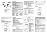
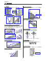
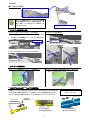
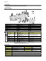
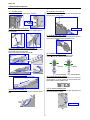
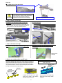
電動式 8mm 幅ダブルレーンフィーダ
Electric Double Tape Feeder
8mm 双轨电子供料器
EF08HD
簡易取扱説明書
SIMPLE INSTRUCTION MANUAL
简易使用说明书
この度は、弊社の製品をお買い上げ頂きましてありがとうございました。
Thank you for purchasing a product of our company.
感谢您购买本公司的产品。
フィーダを安全に使用して頂くために、使用前に必ず本書をお読み頂き十分理解してください。本書はお読みになった後、いつでも
利用できるよう必ず所定の場所に保管してください。この説明書は、フィーダの持つ特有の機能について説明してあります。
注意
フィーダを複数本同時に持ったり、保管時に平積みしたりなど、フィーダ同士が強く接触する事が無いように注意してください。
持ち運び時、フィーダを他のものに当てないように、また落下させないように注意してください。万が一衝撃を受けたときには、異常が
ないかを必ず確認してください。
In order to ensure safe use of the FEEDER, be sure to read this Manual before using the machine. After reading this
Manual, keep it at a fixed location so that it will be available at any time. This manual describes the functions specific to
the FEEDER.
CAUTION
注意
When you carry the FEEDER, be careful not strike it against any other thing or not drop it. If the tape feeder is
subject to impact, check to see if it does not malfunction.
Do not carry two or more FEEDERS at the same time. Do not stack FEEDERS flat during storage so that they
cannot be in contact with one another tightly.
为了能让您安全地使用供料器,在您使用前,请一定仔细阅读本说明书。阅读完本书之后,请妥善保管,以便能随时
查阅。本说明书仅就供料器的有关功能进行说明。
手持搬运时,注意不要使供料器碰撞他物,或掉落。万一受到冲击时,必须检查是否有异常。此外,不要同时手持多
个供料器,保管时不要叠放,要避免供料器互相强撞强压。
産業装置ユニット カスタマーサポート部
〒206-8551 東京都多摩市鶴牧2-11-1
〒564-0052 大阪府吹田市広芝町10-28
オーク江坂ビルディング
CUSTOMER SUPPORT DEPARTMENT
ELECTRONIC ASSEMBLY SYSTEMS BUSINESS UNIT
TEL:042-357-2298
FAX:042-357-2297
TEL:06-6380-2626
FAX:06-6380-2222
2-11-1, Tsurumaki, Tama-shi, Tokyo 206-8551, JAPAN
PHONE: 81-42-357-2318 FAX: 81-42-357-2297
http://www.juki.co.jp/
Copyright © 2011-2012 JUKI CORPORATION All rights reserved
throughout the world.
● 仕様,外観等は改良のためお断りなく変更することがあります。本書の内容を無断で転載、複写することを禁止します。
● The specification and appearance may be changed without notice.
● 规格、外观等若有变更,恕不另行通告。未经许可,严禁私自转载或复印本书内容。
40109411
Rev02
JAPANESE
1 はじめに
本書は主に EF08HD のテープの取り付け・取り外し方法を説明しております。
機能の詳細につきましては、マウンタに添付される『取扱説明書 CD』内の『取扱説明書』と『EF08HD 取扱説明書』を参照願
います。
2 各部名称
7
6
27
5
1
2
3
8
28
4
9
10
11
25
23
24
15
12
13
16
14
22
17 18
No.
1
2
3
4
5
6
7
8
9
10
名称
アッパーカバー(L/R)
スプロケットホイール(L/R)
カバーテープ U ガイド
テンショナアーム(L/R)
アイドラアーム(L/R)
グリップチャンバーフレーム
操作パネル
PP キャップおよびテープサポート保管場所
チャンバーリッド
テープ挿入口(R レーン)
No.
11
12
13
14
15
16
17
18
19
20
19
20
名称
ロックリリースレバー
フロントライナーブロック組
RFID タグ(IS 仕様のみ)
スライドレール
X ガイドピン_R
ロック部(バンククランプ部)
コネクタ
ボトムガイドブロック
定格銘板
レビジョンラベル
21
26
No.
21
22
23
24
25
26
27
28
名称
テープ挿入口(L レーン)
リールサポートガイド
リールサポート L 組
リールサポートアーム
テールガイド
リールフック
PP キャップ
テープサポート
3 操作パネル部
動作名称
LED 表示
送りピッチ設定
イニシャライズ
イニシャライズ完了状態解除
正転ピッチ送り
逆転ピッチ送り
動作停止
エラーリセット
操作レーン切り替え
ボタン操作について
ボタン操作
動作説明
■スイッチを二度押し
02 / 04
▲スイッチまたは▼スイッチで押し、送りピッチを変更
送りピッチを 2mm と 4mm に切り替えます。
■スイッチを二度押し
0H
■スイッチと▼スイッチを同時押し
生産可能な状態にします。
■スイッチを長押し
イニシャライズ状態を解除します。
▲スイッチを長押し
送りピッチ分フィードします。
▼スイッチを長押し
送りピッチ分逆フィードします
■スイッチを単押し
フィード動作やイニシャライズ動作を停止します。
E
■スイッチを単押し
エラー表示を解除します。
スイッチを単押し
操作有効レーン(L⇔R)の切り替えが可能です。
単押し:スイッチを 1 秒未満で押したとき
長押し:スイッチを 1 秒以上押したとき
2 回押し:同じスイッチを 1 秒未満、2 回連続で押したとき
同時押し:2 つのスイッチを同時に押したとき
4 仕様
製品コード
レバー色
外形寸法
電源
電源電圧
テープ幅
エンボステープ使用条件
動作時環境条件
精度保証温度
騒音
過電圧区分
環境汚染度
EF08HD / EF08HD(IS)
送りピッチ
2 / 4mm
青
占有ポジション数
1
全長=911mm, 高さ=455mm, 幅=17mm(リールサポート装着時)
質量
3.0 kg
マウンタ本体から供給
部品搬送方式
モータ駆動
DC24V
許容電流
2.1A
8mm テープを 2 本装着可(0603 素子以上)
テープ種類
紙、エンボス
対応部品エンボス幅4.3mm 以下
対応部品エンボス深さ 3.5mm 以下
温度:10℃~35℃、湿度:30~80%RH (但し、結露なきこと)、標高:1,000m 以下
温度:20℃~25℃
57.7dB(A)
過電圧区分Ⅰ(IEC60664-1) :過電圧が低いレベルに制限された回路からの供給(2 次側低電圧回路等)
汚染度3 :通常環境より汚染が進んだ環境(製造工場等)
(注)部品サイズ及びテープ諸元については、JIS C0806-3(1999)、IEC 60286-3:2007 に準拠します。
1
JAPANESE
5 テープの取り付け方法
テープリールの取り付け・交換時には「電動式フィーダテープリール取付台」で作業を行います。
(1) 電源供給
(6) カバーテープのセット④
取り付け台の「外段取り用コネクタ」をフィーダに接続します。
アイドラアームを押し、ギア部の隙間にカバーテープを 15mm 程度挿入し
ます。
目安 15mm
(2) テープリールをセット(R レーン)
テープリールを台のホルダにセットし、フィーダ内部にテープを送ります。
(7) テープリールをセット(L レーン)
R レーンの場合と同様にテープリールリールサポートにセットし、フィーダ内
部にテープを送ります。((3)から(6)の動作を行います。)
(3) キャリアテープのセット / カバーテープのセット①
装置保護のために、キャリアテープ(長さ 100mm)がセットされていますの
で、アッパーカバーを開いて取り除いてください。その後、リールから送り出
したキャリアテープの送り穴をスプロケットホイールの歯に合わせます。
また、カバーテープはスリットを通します。
(8) イニシャライズ動作
操作パネルより、フィーダのイニシャライズを行います。
・イニシャライズ動作:■スイッチと▼スイッチを同時押し
NG
点滅
イニシャライズ中
(4) カバーテープのセット②
点灯
イニシャライズ後
(9) 供給位置確認
カバーテープをカバーテープガイドに通します。
供給位置に素子があるか確認してください。
素子がなければ、操作パネルの正転ピッチ送り動作を行います。
(10) 余りテープのカット
排出口から飛び出しているテープ先端をカットし、マウンタ本体に取り付
けます。
(5) カバーテープのセット③
テンショナアームを持ち上げ、テンショナローラにカバーテープを通します。
目安 3mm
2
JAPANESE
■テープ取り付け完成図
注意
他の ETF 各機種においても、フィーダバンクや一括交換
台車での段取り時、EF08HD が隣接する場合は、「電
動フィーダ用テープリール取付台」でテープの取り付け、取
り外しを行ってください。
電動フィーダテープリール取付台
6 キャリアテープの取り外し方法
(1) カバーテープをテンショナローラから外し、ハサミで切ります。
(3) キャリアテープを抜き取ります。
テープリール途中交換の場合には、次回取り付けの為に、アイドラア
ームを押して、ギア部の隙間からカバーテープを 15mm 程度引き出し
て、先端部をハサミで切ります。
目安 15mm
(4) レーンからテープを抜き取ります。
(2) アッパーカバーを開き、カバーテープをスリットから外します。
7 カバーテープの廃棄方法
(2) カバーテープを回収し、最後に廃棄口近くでテープを切ります。
(1) チャンバーリッドが開き始めたら、カバーテープを廃棄します。
カバーテープは強く引かないでください。
8 ピックポジションキャップ(PP キャップ)の使用方法
出荷時よりアッパーカバーに取り付けられている PP キャップは、右に示す素子サイズのみに使用します。
これら以外の素子を搭載する場合は PP キャップを取外し、グリップにある収納部へ移してください。
※PP キャップ固定ネジは紛失防止の為、PP キャップ取外し時もアッパーカバーに付けてください。
PP キャップ使用素子サイズ
0603 / 1005 / 1608
グリップ
固定ネジ
PP キャップ
アッパーカバー
PP キャップ取付時は
グリップにある収納部へは、
矢印方向へ軽く突き当てる
溝に合わせて指で押し込む
3
ENGLISH
1 Introduction
This manual mainly explains how to attach or detach a tape reel for EF08HD.
For detailed functions, refer to "Instruction Manual" in "Instruction Manual CD version" attached to a mounter and also "EF08HD
Instruction Manual. "
2 Name of each part
7
6
27
5
1
2
3
8
28
4
9
10
11
25
23
24
15
12
13
14
16
22
19
17 18
No.
1
2
3
4
5
6
7
8
9
10
Description
Upper cover (L/R)
Sprocket wheel (L/R)
Cover tape U guide
Tensioner arm (L/R)
Idler arm (L/R)
Grip chamber frame
Operation panel
Storage space for PP cap and Tape support
Chamber lid
Tape loading slot (R lane)
No.
11
12
13
14
15
16
17
18
19
20
20
21
Description
Lock release lever
Front liner block assy
RFID tag (for the IS specification only)
Slide rail
X guide pin R
Lock section (Bank clamp section)
Connector
Bottom guide block
Rating plate
Revision label
26
No.
21
22
23
24
25
26
27
28
Description
Tape loading slot (L lane)
Reel support guide
Reel support L assy
Reel support arm
Tail guide
Reel hook
PP cap
Tape support
3 Operation panel section
LED
display
Name of operation
Feed pitch setting
02 / 04
Initialization
Initialization completion state
cancellation
Normal rotation pitch feed
Reverse rotation pitch feed
Operation stop
Error reset
0H
Operation lane change
Button operation
E
Button operation
Explanation of operation
Press ■switch button twice
Press ▲ switch button or ▼ switch button to
change a feed pitch
Press ■switch button twice
Press ■switch and ▼switch at the same time
To switch a feed pitch to 2 mm and 4 mm
To put it into states that can be produced
Press and hold ■switch button long
To cancel initialization state
Press and hold ▲switch button long
Press and hold ▼switch button long
Press ■switch button short
Press ■switch button short
To feed a tape by a pitch
To reversely feed a tape by a pitch
To stop feed operation and initialization operation
To cancel error display
To be able to change operation effective lane
(between L and R)
Press
switch button alone
Press a switch button short:: for less than one second
Press a switch button long: for one second or more
Press a button twice: the same switch button for less than one second and two times in sequence
Press a button at the same time: two switch buttons at the same time
4 Specification
Product code
Color of lever
Outside dimensions
Power supply
Power-supply voltage
Tape size
Emboss tape conditions
Operation environmental
conditions during operation
Accuracy guarantee
temperature
Noise
Excessive voltage class
Environmental pollution level
EF08HD/EF08HD (IS)
Blue
Entire length: 911 mm, height: 455 mm,
and width: 17 mm(A reel support is attached.)
Supplied from a mounter
DC 24V
Available two 8 mm tapes
(0603 or bigger component)
Applicable component emboss width : 4.3 mm or less
Feed pitch
Number of occupied positions
2 and 4 mm
1
Mass
3.0 kg
Component transporting method
Allowable current
Motor-driven
2.1A
Tape types
Paper and embossed tapes
Applicable component
emboss depth : 3.5 mm or less
Temperature: 10℃ to 35℃, humidity: 30 to 80% RH (No condensation), altitude: 1,000 m or less
Temperature: 20℃ to 25℃
57.7 dB(A)
Class 1 (IEC60664-1): Excessive voltage is supplied from the circuit whose voltage is limited to a low level (such as a secondary low
voltage circuit)
Level 3: Environment whose pollution is worse than that of the normal environment (such as a manufacturing plant)
* Use components whose size and tape specifications conform to JIS C0806-3:1999 and IEC 60286-3:2007.
3
ENGLISH
5 How to attach a tape reel
Use an " Feeder setup stand for Electric feeder" when attaching or replacing the tape reel.
(1) To supply power
(6) To set the cover tape ④
Connect a "connector for off-line setups" of the unit.
Push the idler arm to insert the cover tape into the gap in the
space of gear by some 15 mm.
Guide 15 mm
(2) To set the tape reel (R lane)
Set the tape reel at the holder of the unit to feed the tape into
the tape feeder.
(7) To set the tape reel (L lane)
Just as R lane, Set the tape reel at the reel support to feed the
tape into the tape feeder. (follow procedures 3 to 6)
(3) To set a carrier tape and a cover tape ①
Open the upper cover to insert feed holes of the carrier tape
into the teeth of the sprocket wheel.
Moreover, pass the cover tape under the slit.
(8) To initialize the tape feeder
Initialize the tape feeder with the operation panel.
・Press ■ and ▼ switches at the same time.
No good
Flashing
During initialization
(4) To set the cover tape ②
Lighting
After initialization
(9) To check the supply position
Pass the cover tape under the cover tape guide.
Check to see if a component is located at the component
supply position. If it is not, perform the normal rotation pitch
feed operation with the operation panel.
(10) To cut the remaining tape
(5) To set the cover tape ③
Cut the end of tape protruding from the tape ejecting slot and
attach the tape to the mounter.
Lift the tension arm to pass the cover tape under the tension
roller.
Guide 3 mm
5
ENGLISH
■ As-fitted picture of tape attachment
CAUTION
Regarding the other ETF models, mount and
dismount a tape by using the “Feeder setup stand for
Electric feeder” when EF08HD is adjacent at
preparation in the feeder bank or Feeder trolley.
Feeder setup stand for Electric feeder
6 How to detach a carrier tape
(1) Detach the cover tape from the tension roller, and cut it
with scissors.
When replacing the tape reel halfway, press the idler arm to
attach it next time. Pull out the cover tape from the space of
gear by some 15 mm, and cut its end with scissors.
(3) Pull the carrier tape.
Guide 15 mm
(4) Pull the tape from the lane.
(2) Open the upper cover, and detach the cover tape from the slit.
7 How to discard a cover tape
(2) Extract the cover tape, and cut it near the cover tape
discharging slot.
At this time, do not pull the cover tape strongly.
(1) Discard the cover tape when the chamber lid begins to open.
Storage section
of the grip
8 How to use a pick position cap (PP cap)
The PP cap attached on the upper cover at the factory is to be used for
components whose sizes are shown on the right side.To place a
component other than those components on a board, remove the PP cap
from the upper cover, and then store it in the storage section of the grip.
*To prevent the setscrew of the PP cap from being lost, leave it fixed on
the upper cover when the PP cap is removed.
Components for which the PP cap is used
0603 / 1005 / 1608
Storage section
of the grip
Setscrew
PP CAP
Upper Cover
To attach the PP cap on the upper
cover, push it gently in the direction
indicated with the arrow mark.
6
Push the PP cap with a finger along
the groove into the storage section
of the grip.
CHINESE
1 前言
本书主要对 EF08HD 带子的安装·拆卸方法进行说明。
详细功能,请参见贴片机附带的『使用说明书 CD』内的『使用说明书』及『EF08HD 使用说明书』
2 各部名称
7
6
27
5
1
2
3
8
28
4
9
10
11
25
23
24
15
12
13
16
14
22
17 18
名称
19
20
名称
21
26
No.
1
上护罩(左/右)
No.
11
解锁把
No.
21
名称
带子插入口 (左轨)
2
链轮齿(左/右)
12
前侧导块组
22
卷筒支撑导块
3
护带 U 导块
13
RFID 标签(只限 IS 规格)
23
卷筒支撑左组
4
5
张力臂(左/右)
空转臂(左/右)
14
15
滑轨
X 导销_右
24
25
卷筒支撑臂
尾部导块
6
把手排带箱架
16
锁定部(台架锁定部)
26
卷筒钩
7
操作面板
17
连接器
27
PP 导向块
8
PP 导向块及带子支撑台保管位置
18
底部导块
28
带子支撑
9
排带箱盖
19
额定标牌
10
带子插入口 (右轨)
20
校订标签
3 操作面板部
动作名称
LED 显示
设置传送间距
初始化
解除初始化完成状态
正转间距传送
反转间距传送
停止动作
错误复位
切换操作轨道
关于按钮操作
按钮操作
按两次■开关
02 / 04
按▲开关或▼开关,变更传送间距
按两次■开关
0H
同时按■开关和▼开关
长按■开关
长按▲开关
长按▼开关
按一次■开关
E
按一次■开关
按一次 开关
按一次:按下开关不到 1 秒时
按两次:同一开关连续两次按,每次不到 1 秒时
动作说明
切换传送间距为 2mm 或 4mm。
使之进入可生产状态。
解除初始化状态。
正转传送一个间距。
反转传送一个间距。
停止传送动作或初始化动作。
解除错误显示。
可切换操作有效轨道(左⇔ 右)。
长按:按下开关 1 秒以上
同时按开关:同时按下两个开关时
4 规格
产品代码
杆杠颜色
外形尺寸
电源
电源电压
带子宽度
压纹使用条件
运行时环境条件
精度保证温度
噪音
过电压区分
环境污染度
EF08HD / EF08HD(IS)
传送间距
2 / 4 mm
蓝色
占有位置数
1
全长=911mm, 高度=455mm,
3.0 kg
重量
宽=17mm(安装卷带支撑架时)
从贴片机供给
元件传送方式
马达驱动
DC24V
容许电流
2.1A
8mm×2 安装(0603 元件以上)
带子种类
纸、压纹
对应元件压纹宽度: 4.3mm 以下
对应元件压纹深度: 3.5mm 以下
温度:10℃~35℃、湿度:30~80%RH (但,不可有露水)
、标高:1,000m 以下
温度:20℃~25℃
57.7dB(A)
过电压区分Ⅰ(IEC60664-1) :从过电压限制为低水平的电路供给(2 次侧低电压电路等)
汚染度 3 :比通常环境汚染更重的环境(制造工厂等)
*元件尺寸及带子规格方面,请使用JIS C0806-3:1999,IEC 60286-3:2007 规格的产品。
7
CHINESE
5 带子的安装方法
安装或更换带子卷筒时,要在「电动供料器用带筒安装台」上进行作业。
(1) 供给电源
(6) 安装护带④
将安装台的「外部准备用连接器」插到供料器上。
推一下空转臂,把护带插入齿轮隙缝约 15mm。
大致 15mm
(2) 安装带子卷筒(右轨)
将带子卷筒安装到台上的架子里,将带子插入供料器内。
(7) 安装带子卷筒(左轨)
与 R 通道的情况同样,将料带安装到料带支承架上,再将料带
送到飞达里面。做(3)到(6)的动作。
(3) 安装载带/ 安装护带①
为了保护装置,设置了载带(长度 100mm)
,请打开上护罩将其
除去。之后把从卷筒传出的载带的传送孔对准链轮齿。
把护带从槽里穿过去。
(8) 初始化动作
在操作面板上,进行供料器的初始化。
・ 初始化动作:同时按下■开关和▼开关
No good
闪烁
初始化中
(4) 安装护带②
亮灯
初始化后
(9) 确认供给位置
把护带从护带导块穿过去。
请确认供给位置上是否有元件。
若没有元件,请执行操作面板的正转间距传送动作。
(10) 剪去多余的带子
把排出口出来的带子头剪掉,接到贴片机主机上。
(5) 安装护带③
把张力臂抬高一下,让护带穿过张力辊。
大致 3mm
8
CHINESE
■带子安装完成图
注意
对于其他 ETF 的各个机种,在供料器支架或一次性更换台车进行
准备时,若与 EF08HD 相邻,请使用「电动供料器用带筒安装
台」执行带的安装和取下。
电动供料器用带筒安装台
6 载带的拆卸方法
(1) 从张力辊上把护带拆下来,用剪子剪断。
(3) 拔出载带。
中途换带子卷筒时,为下次安装时使用,请推一下空转臂,
从齿轮缝隙把护带拉出约 15mm,用剪子剪断头部。
大致 15mm
(4) 从轨道里拔出带子。
(2) 打开上护罩,从槽里把护带卸下来。
7 护带的废弃方法
(2) 回收护带,最后在废弃口附近剪断带子。
(1) 排带箱开始打开,就要废弃护带。
但此时要注意不要强拉护带。
8 Pick Position Cap(PP CAP)的使用方法
由于出货时,上护罩上安装的 PP CAP 仅用于右图所示的芯片尺寸。
贴装除此以外的元件时,请拆下 PP CAP,放入 Grip 收纳部位。
※为了防止 PP CAP 固定螺丝丢失,拆下 PP CAP 时也请安装到上护罩上。
使用 PP CAP 的芯片尺寸
0603 / 1005 / 1608
Grip 收纳部位
固定螺丝
PP CAP
Upper Cover
安装 PP CAP 时,向箭头
方向轻轻顶住。
9
请用手指按进 Grip 收纳部位的沟槽里
![ÿþA - 0 0h‹ˇ}2 0 1 2 [ 1 ] . 1 0 . 1 3](http://vs1.manualzilla.com/store/data/006555814_3-4afa02befe2c0953304d3aefec96187a-150x150.png)