1
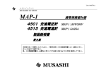
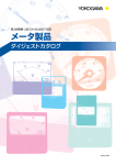
User’s
Manual
2011, 2012
携帯用直流電流計・電圧計
Portable DC Ammeters & Voltmeters
取扱説明書
2011 33
2012 00
IM 2011-01
2008. 10 6 版
6th Edition: Oct. 2008
取扱説明書
INSTRUCTION MANUAL
本器を安全にご使用いただくために,ご使用に先だって以下
に記載された警告文,および取扱説明書<本文>を必ずお読
みいただき,注意,使用方法についての内容は必ず守ってく
ださい。
The following general safety precautions must be observed during all phases of operation, service and repair of this instrument.
Failure to comply with these precautions or with specific WARNINGS given elsewhere in this manual violates the safety standards
of the design, manufacture and intended use of the instrument.
本器および取扱説明書には安全記号
が表示されています。
この安全記号は,人体および機器を保護するために,取扱注
意の警告,取扱説明書や添付資料を必ず読む必要があること
を警告しています。
警 告
感電の恐れがありますので,以下のことを必ず守って
ください。
・ 計器および付属機器を接続する場合は,回路が活線状態で
ないことを確認してから行ってください。
・ 接続端子は,
緩みのないように確実に締め付けてください。
・ 通電中は,入力端子およびその他の端子またはプラグ挿入
口等に触れないでください。
・ 通電中は,ケースおよびカバーを開けないでください。
・ 通電中のレンジ切り替えのためのプラグの差替えは,危険
ですので行わないでください。
YOKOGAWA assumes no liability for the customer's failure to
comply with these requirements.
The safety symbol
is shown both on the instrument and
throughout the instruction manual to draw attention to the necessary safety precautions.
WARNING
To avoid injury or death to personnel and damage to the
instrument, be sure to comply with the following.
• Make sure that the source voltage is not alive before you
attempt to connect the instrument to the circuit.
• Once you have connected the instrument to the circuit,
tighten the terminals.
• Never touch the terminals of plug holes when operating the
instrument.
• Never open the case or cover when operating the instrument.
• Never change the plug at the terminal when operating the
instruments.
目次
概 要 ............................................................................
取扱法および使用上の注意 ........................................
使用法 ............................................................................
保 守 ............................................................................
仕 様 ............................................................................
CONTENTS
1
2
3
5
6
保 証
本器は,厳密な社内検査を経て出荷されておりますが,万一
製造上の不備による故障あるいは輸送中の事故等による故障
の節は,お買上げいただいた販売店または当社販売員にお申
しつけください。
当社製品の保証期間はご納入日より 1 か年です。この間に発
生した故障で,原因が明らかに当社の責任と判定された場合
には無償修理いたします。
INTRODUCTION ............................................................... 1
OPERATING INSTRUCTIONS ......................................... 2
DIRECTIONS ..................................................................... 3
MAINTENANCE ................................................................ 5
SPECIFICATIONS ............................................................. 6
Warranty
The 2011 and 2012 instruments are shipped only after stringent in-house inspection. Should the instrument suffer damage that is attributable to improper manufacture or an accident during transport, contact the sales representative from
which you purchased the product or your nearest YOKOGAWA
sales office.
All products of YOKOGAWA are guaranteed for a period of
one (1) year from the date of delivery.
YOKOGAWA will repair the product in question, free of charge,
if the product fails during the guarantee period for reasons
that are evidently attributable to YOKOGAWA.
概 要
INTRODUCTION
A taut-band suspension system is used in all YOKOGAWA portable DC
ammeters & voltmeters. This system has no pivot and jewel bearings so
these portable instruments are friction less and thoroughly resistant to shock
and vibration.
当社の携帯用直流電流計,電圧計は,すべてトートバンド支持方
式を採用していますので摩擦がなく再現性がすぐれ,
振動や衝撃に対
しても極めて強い特長をもっています。
さげ手
Handle
測定端子
Terminal
目盛板
Dial
指針
Pointer
ミラー
Mirror
計器カバー
Cover
零位調整器
Zero Adjust Screw
Fig.1
― 1 ―
取扱法および使用上の注意
1.
2.
3.
4.
5.
6.
7.
8.
OPERATING INSTRUCTIONS
1. Do not use these instruments in a location exposed to direct sunlight, an
external magnetic field or mechanical vibration or in a high-temperature
highly humid environment.
2. Place the instrument on a fairly level surface. A horizontal position will
give the highest accuracy.
3. When using a number of these instruments in an array, keep them as far
away from each other as possible.
4. Before wiring any of these instruments, carefully check the measuring
ranges and polarities. When wiring, securely fasten the terminals and
plugs. When a large current needs to be measured, use wire that is both
thick enough and has sufficient current-carrying capacity.
5. Before measurement, check that the pointer coincides exactly with the
zero scale point. If it does not, turn the zero adjust screw provided on the
meter cover until the pointer meets the zero scale point.
6. Be careful not to apply an unreasonably large current or high voltage to
the instrument.
7. For the optimum instrument accuracy, select a measuring range such that
the indication may be read in the top half of the scale.
8. Try not to apply too much force when wiping the glass window surface
of the instrument during measurement. Doing so may result in a deviation in the indication due to static electricity. If the surface is dirty, gently
clean it using a dry, soft cloth.
計器は,直射日光の当たる場所,外部磁界のある場所,振動のあ
る場所,あるいは高温高湿な環境では使用しないでください。
計器は,常に水平位置(標準姿勢)で使用してください。このと
き最も正確な指示が得られます。
多数の計器を並べて使用するときは,
でき得る限り離して使うよ
うにしてください。
計器の結線に先だち測定範囲,極性等をよく確認し,端子の締付
けあるいはプラグの締付けは確実に行ってください。また大電流
の測定時には,その接続導線の電流容量にも注意をはらい十分太
い線で行ってください。
測定に入る前に指針が目盛の零位に一致していることを確めま
す。もし一致していなければ零位調整器を左右に回して合わせま
す。ミラーに映った指針の像と指針とが一致する目の位置で行っ
てください。ただし,指針の曲がりで零位の狂ったものは,誤差
の原因となりますので,零位調整器で合わせないようにしてくだ
さい。
計器に,
その最大目盛値以上の値をみだりに加えないよう注意し
てください。測定値があらかじめ予測できない場合には最も大き
い測定範囲から順次下位に換えて測定してください。
測定の精度を高めるために計器の指示はなるべく最大目盛値から
その 1/2 の間の目盛で読みとれるような測定範囲の計器を選びま
す。
測定中に計器の窓ガラスの表面を乾いた布で強く拭きますと静電
気のため指示が変化することがありますので避けてください。特
に乾燥期にはご注意ください。
表面の汚れは,乾いた柔かい布で軽く拭きとってください。
― 2 ―
使用法
DIRECTIONS
1. Models 2011 and 2012 are permanent-magnet moving-coil types that are
used for DC measurement only. Therefore, if a current such as a rectified
wave (i.e., a pulsating current) is measured, the instrument will indicate a
mean value.
2. To measure a DC current you can use the 50 mv 2011 instrument or the
2012 instrument that is set to the 50 mv range and has either a 2215 or
2217 external shunt. To connect the instrument, use the pair of lead wires
(each 1.5 m and 0.025 Ω) provided. If these lead wires are not available,
use a pair of lead wires whose total resistance is less than 1 Ω so that
errors due to the resistance are negligible.
3. When measuring voltages higher than 1000 V, use either the 3 V 2011
instrument or the 2012 instrument with an external voltage multiplier
connected to its 3 V terminal.
2011,2012 は,永久磁石可動コイル形計器で直流専用の計器で
す。したがって整流した波形が脈動していますと,計器はその平
均値を指示します。
2. 2011 の 50 mV 計器または 2012 の 50 mV 端子と外付分流器とを
組み合わせて直流電流を測定する場合は,付属の分流器接続導線
{1.5 m 0.05 Ω (往復)}を使用してください。これ以外の導線を用
いる場合でも,その抵抗器が0.1 Ω以下であれば導線抵抗による誤
差は無視できます。
3. 1000 V をこえる直流電圧の測定には,2011 の 3 V 計器または
2012 の 3 V 端子に外付直列抵抗器を直列に接続して使用します。
1.
― 3 ―
分流器
Shunt
2216
分流器は水平位置に設置する。
Place the shunt on a fairly level surface.
直列抵抗器
Series resistor
2222
ブスバー
Bus bar
分流器接続導線
Lead
(0.025Ω×2)
接触抵抗が発生しないよう
に締付けを確実に行う。
Tighten terminal when
connecting the shunt to
the circuit.
2011 50 mV計器または2012 50 mV端子
The 50 mv 2011 instrument (2011-41) or the
2012 instrument set to the 50 mv range.
2011 3 V計器または2012 3 V端子
The 3 V 2011 instrument (21011-42) or
the 2012 instrument set to the 3 V range.
Fig.3
Fig.2
― 4 ―
保 守
MAINTENANCE
1.
計器の保管は,
直射日光の当たらない湿気の少ない場所にしてく
ださい。また,埃りがかからないようにご留意ください。
2. 精度を確保し,
常に正しい精度で測定するためにも定期的な校正
をおすすめします。
校正の周期は,計器の使用頻度や使用条件により異なりますが,
3 か月に 1 ∼ 2 回行えば理想的です。
1. To ensure good measurement, keep the instrument free of dust, moisture,
and away from direct sunlight.
2. If an overload or excessive shock has caused the accuracy of the instrument to become doubtful, check several scale points and compare these
readings with an instrument which has been properly calibrated.
If the accuracy of the instrument is found to differ from its rating,
recalibrate the instrument.
Ideally, the instrument should be calibrated once or twice every three
months, though this depends on the instrument's frequency of use and
operating conditions.
アフターサービス
NOTE
If any troubles occur in the instrument, contact your nearest YOKOGAWA
Sales office or sales agent.
正常な動作を示さず修理を要する場合には,当社
または販売代理店へお申しつけください。
― 5 ―
仕 様
SPECIFICATIONS
Operating Principle:
Permanent-magnet moving coil
Operating Temperature and humidity range: 0 to 40°C, 25 to 80% RH
Storage Temperature and humidity range: -10 to 50°C, 25 to 80% RH
Deflection Angle:
Approx. 85°
Scale Length:
Approx. 135 mm
Insulation Test:
Between electrical circuit and case
DC 500 V / More than 10 MΩ
Voltage Test:
3000 V AC, for 5 seconds between measuiring
circuit and case
Weight:
2011 approx. 1.7 kg
2012 approx. 2.8 kg
Optional Accessories:
Carrying case model 2291 for 2011
Carrying case model 2292 for 2012
動 作 原 理 : 永久磁石可動コイル形
使用温湿度範囲 :0 ∼ 40℃,25 ∼ 80% RH
保存温湿度範囲 :-10 ∼ +50℃,25 ∼ 80% RH
指 針 振 れ 角: 約 85°
目 盛 長: 約 135 mm
絶 縁 試 験 : 電気回路と外箱間 DC500 V にて 10 MΩ 以上
電 圧 試 験 : 電気回路と外箱間 3000 V AC,5秒間
質 量: 2011 約 1.7 kg
2012 約 2.8 kg
アクセサリ(別売): 2011 用携帯用かばん 2291
2012 用携帯用かばん 2292
― 6 ―
形名
Model
2011
コード
Code
最大目盛値
Range
概略内部抵抗,消費電流
Approx. internal resistance, etc.
31
32
33
34
35
36
37
3/10/30/100
10/30/100/300
0.1/0.3/1/3
1/3/10/30
10/30/100/300
0.1/0.3/1/3
1/3/10/30
µA
µA
mA
mA
mA
A
A
38
39
40
0.3/1/3/10
3/10/30/100
30/100/300/1000
V
V
V
電圧降下 Voltage drop:50 mV
1 mA (1000 Ω/V)
41
分流器外付用計器(50 mV)
For use with external shunt (50 mV)
(500 µA)
42
直列抵抗器外付用計器(3 V)
For use with external Series Resistor (3 V)
(1 mA)
3/10/30/100/300/1000 V
1/3/10/30/100/300 mA
1/3/10/30 A 50 mV
2012
5.1/18.3/7.7/2.5 kΩ
6.8/6.8/3.5/0.88 kΩ
750/750/278/97.5 Ω
23/14/4.7/1.6 Ω
00
(17種測定範囲 17 range)
電圧測定 Voltage measuring range: 1 mA (1000 Ω/V)
電流測定 Current measuring range:
50 mV : 59 Ω
300 mA : 51 mV
1 mA : 24 mV
1A
: 53 mV
3 mA : 41 mV
3A
: 56 mV
10 mA : 47 mV
10 A
: 75 mV
30 mA : 49 mV
30 A
: 100 mV
100 mA : 50 mV
注) 1. 30 A を超える測定には,2011 41(50 mV 計器)または 2012 の 50 mV 端子に分流器 2215 ∼ 2217 を外付して使用します。
2011 41(50 mV 計器)および 2012 には分流器導線 1 組(1.5 m, 0.05 Ω)を付属します。
導線抵抗が 0.1 Ω 以下であれば付属以外の導線を使用しても支障ありません。
2. 1000 V を超える測定には,2011 42(3 V 計器)または 2011, 2012 の 3 V 端子に直列抵抗器 2222 ∼ 2223 を外付して使用します。
Note: 1. When measuring currents of greater than 30 A, attach a 2215, 2216 or 2217 shunt to the 2011-41 (50 mV volt-ammeter) or the 50 mV terminal of 2012.
Both the 2011 and 2012 volt-ammeters are supplied with a pair of lead wires (1.5 m, 0.05 Ω). Other types of lead wires can be used as long as their resistance is no greater than 0.1 Ω.
2. When measuring voltages of greater than 1000 V, attach the 2222 or 2223 external Series Resistor to the 2011-42 (3 V volt-ammeter) or the 3 V terminal of 2012.
― 7 ―
<アクセサリ Accessories>
●分流器 EXTERNAL SHUNTS
形名
Model
コード
Code
2215
08
09
10
11
12
13
14
15
16
15 A
20 A
30 A
50 A
75 A
100 A
150 A
200 A
300 A
50 mV
2216
01
02
03
500 A
750 A
1000 A
50 mV
2217
01
02
03
04
1500 A
2000 A
3000 A
5000 A
50 mV
定格
Rating
●直列抵抗器 SERIES RESISTORS
形名
Model
コード
Code
定格
Rating
消費電流
Current consumption
2222
01
02
03
0.75/1.5 kV
1/2 kV
1.5/3 kv
1 mA
1 mA
1 mA
2223
00
3/5 kV
1 mA
注)外付分流器,直列抵抗器とも0.2級
Note: The accuracies of the shunts and series resistors are ±0.2% of the rated value for all models.
― 8 ―
Printed in China