1
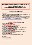
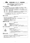
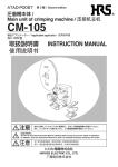
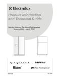
取扱説明書
Instruction Manual
MARUYASU INDUSTRIES CO.,LTD.
チューブコア式盤用熱交換器
TUBE CORE HEAT EXCHANGER
この度はチューブコア式盤用熱交換器をご購入していただき、誠にありがとうございます。
ご使用になる前に必ずこの取扱説明書をよくお読みください。
この取扱説明書は大切に保管して下さい。
Thank you very much for your purchasing our tube core heat exchanger.
Read this instruction manual carefully before using our products.
Keep this instruction manual at hand.
INDEX
1. 注意事項
・・・・・・・・・・・・・・・・・・・・・・・・・・・・・・・・・・ 1
Cautions
・安全に関するご注意
・盤への取付方法
・運転方法
2. 取付手順
・・・・・・・・・・・・・・・・・ 1
Installation to panel
・・・・・・・・・・・・・・・・・ 1
Operating method
Installation procedure
3. 熱交換器の構造
4. メンテナンス
5. 保証期間
Safety notices
・・・・・・・・・・・・・・・・・・・・・・・・ 2
・・・・・・・・・・・・・・・・・・・・・・ 2
Structure of heat exchanger
Maintenance
Warranty period
・・・・・・・・・・ 3
・・・・・・・・・・・・・・・・・・・・・・・・・ 3
・・・・・・・・・・・・・・・・・・・・・・・・・・ 4
この取扱説明書にはチューブコア式盤用熱交換器についての安全に関する注意・取付方法・運
転・メンテナンスについての一般的指示を記載していますが、記載されている内容が万全では
ありません。安全に対しては、常に常識を働かせ、自分自身でも注意・確認を怠らないことを
心掛けて下さい。
This instruction manual describes general instructions about safety notices, installation
procedure, operation and maintenance of a tube core heat exchanger, but the contents of this
manual are not perfect. As for safety, always apply common sense and commit yourself to
keep cautious and confirming.
MARUYASU INDUSTRIES CO., LTD.
1.
注意事項
Cautions
この商品は、盤用熱交換器として開発された物です。本来の目的である、ボックスの冷却以外にはご使用にならないでください。この取扱説明
書に示した注意事項は、安全に関する重大な内容を記載しておりますので必ず守ってください。
表示と意味は下記のようになっています。
危険
Danger
取扱いを誤った場合、使用者が死亡または重傷を負う危険が切迫して生じる事が想定される場合。
An immediate hazard that could result in death or serious injury, if instructions are not
observed.
注意
Caution
取扱いを誤った場合、使用者が損害を負う危険が想定される場合及び、物損事故のみの発生が想
定される場合。
A hazard that could result in minor to moderate injury or a situation that could result in
equipment damage, if instructions are not observed.
・安全に関するご注意
危険 Danger
通電中は端子台に絶対触らないで下さい。
Never touch the terminal block when current is applied.
注意 Cautions
熱交換器が納入された時、その梱包状態が損傷していない事。
梱包の損傷は、故障の原因になる場合がございます。ご注意下さい。
There should be no damage on packaging when the heat exchanger is delivered.
Note that damage on packaging may cause a failure of the product.
保管及び使用は、周囲温度範囲が−10℃∼70℃、周囲湿度が 20%RH∼85%RH(結露なきこと)の環境です。
Store and use the product in an environment with ambient temperature from -10 to 70℃ and ambient humidity from
20%RH to 85%RH (no condensation).
腐食性ガスのある場所では使用出来ません。
This product cannot be used in a corrosive gas environment.
屋外での使用はできません。
This product cannot be used in the open air.
振動・衝突のある場所では使用できません。
This product cannot be used where noise and vibration exists.
運搬する場合は、衝撃・振動・ムリな荷重は加えないでください。
ファンモーターの寿命の低下、異音、破損の原因になります。
When transporting, do not apply shock, vibration and unreasonable load.
These may cause a reduced life, abnormal noise, or failure of the fan motor.
オイルミスト環境での使用は適宜にフィルターのメンテナンスを実施してください。
Carry out filter maintenance at appropriate intervals, if used in an oil mist environment.
この取扱説明書の内容をすべて読んでいただき、正しい方法で取付、メンテナンスを行ってください。
Read through this instruction manual and carry out proper installation and maintenance.
・盤への取付方法 Installation to panel
注意 Cautions
・
・
・
・
・
・
電源への接続工事及び万一の修理は、必ず専門の業者にお任せ下さい。
Contact to professionals for connecting work and unexpected repair work.
漏電による感電防止のために、アースビスより必ず接地して下さい。
To prevent an electric shock due to leakage, connect the unit to ground with an ground screw.
電源は必ず銘板に表示してある電圧(±10%)で使用して下さい。
Select a power supply according to the voltage displayed on the rating plate (±10%).
電源取入れ口には、必ず適切なブレーカを介して接続して下さい。
Connect a power supply inlet through an adequate breaker.
端子台のネジは標準トルク(1.4N・m)で確実に締付けて下さい。端子台ネジのゆるみは発熱、火災の原因となります。
Be sure to tighten the screws of the terminal base with a normal torque (1.4 Nm). Loosing of these screws may cause
heating or a fire.
端子台極間に於ける接点空間距離は、3mm 以上保てるよう、端子の傾き等に注意して下さい。また、過剰な複数接続をしない
で下さい。
To keep the distance between the contacts of the terminal base 3 mm or more, pay attention to the slope of the
terminals. Do not connect excessively multiple terminals.
-1-
注意 Cautions
・
・
・
・
熱交換器は必ず水平、垂直(±2°)に取付けて下さい。
The heat exchanger must be mounted horizontally or vertically(±2°).
制御盤の取付け面は、熱交換器を取付けた時に、反ることのない様にして下さい。取付け面のパッキンにスキマができるため
に、盤外の粉塵やミストが制御盤内に侵入する恐れがあります。
The mounting surface of the control panel should not be warped when the heat exchanger is mounted. This causes a
gap in a packing on a mounting surface, and dust and mist could enter into the control panel.
熱交換器本体正面、側面及び上部に対し、他のユニットまたは壁と 150mm 以上離して下さい。十分なスペースが無く、空気循
環が悪いと熱交換能力が低下します。
Take 150 mm or more distance between the front, side, and top surfaces of the heat exchanger and other units or walls.
Insufficient distance leads to a bad air circulation and causes reduced heat exchange ability.
メンテナンス作業で、制御盤の扉を開けたり、熱交換器を外したりすること考えられる制御盤内部に於いて、熱交換器取付部の
下方には、電気機器を配置しないで下さい。万一、オイルや水が浸入した場合、滴下によるショート災害の恐れがあります。や
むを得ず、下方に設置する場合は、オイルパンなどのカバーを設け、事故予防をして下さい。
In the control panel where it is conceivable that the door of the control panel is opened or the heat exchanger is
removed during maintenance work, do not locate electrical devices under the heat exchanger. In the event that oil or
water enters into the control panel, this could cause a short circuit accident due to dripping. When the devices are
inevitably located under the heat exchanger, install a cover such as an oil pan to prevent the accident.
・運転方法 Operation method
熱交換器は通電により運転を開始し、ファンモーターにより連続的な空気循環をします。
The heat exchanger starts its operation when electric current is applied and continuously circulates air with the fan motor.
注意 Cautions
・
・
2.
フィンガーガードをはずしたままでの運転は絶対にしないで下さい。
Never operate while the finger guard is detached.
ファンモーターの穴に指や工具を入れないで下さい。けがや故障の原因になります。
Do not insert a finger or tool into the hole of the fan motor. Doing so could cause injury or failure.
取付手順
Installation procedure
(1) 本体取付 Installation of main body
・ 取付に必要なネジ・ナット等を準備して下さい。
Prepare screws and nuts necessary for installation.
・ 対象品番の製品図面に指示してあります「パネル加工図」に従い、開口部及びスタッドボルト加工(またはネジ穴)を取付面に加工して
下さい。
According to a Panel processing drawing indicated in a product drawing of reference number, process the mounting surface
for an opening and stud bolts (or screw holes).
・ パネルカットに合わせ、熱交換器を固定して下さい。尚、取り付け時は、パッキン面全体が均一に密着できるよう注意しながら、少しずつ
ネジを締め、全て、トルク 1.4N・m で締め付けて下さい。
Fix the heat exchanger in accordance with a panel cut-out. When installing, drive screws carefully and slowly to allow the whole
surface of packing contacts evenly, and tighten up all screws with a torque of 1.4 Nm.
・ 制御盤の取付穴(スタッドボルト)と、本体の取付穴の位置が、わずかに合わない場合を考慮して、取付穴は若干大きくしてありますが、
極端にずれている場合は、制御盤側の取付を修正して下さい。
・The mounting holes have been processed slightly larger in consideration of the case when the locations of the screw holes (or
stud bolts) of the control panel and the locations of the mounting holes of the main body are slightly misaligned. But if they
deviate extremely, correct the mounting portions of the control panel.
(2) 電源接続 Connection of power supply
・ 電源は必ず表示電圧に合わせ、ラベル表示通りに接続して下さい。ラベルの表示は、Fig1,2,3 のようなものがあります。
A power supply must be in accordance with the indicated voltage and must be connected following the indication of the label.
The indication labels are shown in Figs. 1 to 3.
【Fig.1】
【Fig.2】
【Fig.3】
・ 「盤への取付方法」に記載してある内容に従い、トルク 1.4N・m で確実に締め付けて下さい。
According to the contents described in Installation to panel, surely tighten up the screws with a torque of 1.4 Nm.
・ 端子台接続後は、カバーを取付けて下さい。
Attach a cover after the terminal base is connected.
(3) シーリング処理 Sealing treatment
・ 取付面パッキンに隙間がある場合は、シーリング処理して下さい。
Apply sealing treatment if there is a gap between mounting surface and packing.
-2-
3.
構造 Structure
・熱交換器 Heat exchanger
本製品は、油煙・塵埃などが浮遊する悪環境に置かれ
る制御盤内部の温度上昇を防止するための機器です。
「チューブコア」とは、本製品を構成する弊社独自の放熱
ユニットです。多数のチューブ(パイプ)からなるユニットは、
盤内外を明確に仕切り、油煙・塵埃の侵入を防ぎます。
盤内の暖かい空気を、内部ファンモータによりチューブ
(パイプ)内面に強制循環し、盤外の冷たい空気を、外部
ファンモータによりチューブ(パイプ)外面に強制循環しま
す。この連続運転によって温度差を中和し、盤内の温度
上昇を抑えます。
The warm air inside the panel is forcibly circulated through the inside
of tubes (pipes) with the internal fan motor and the cool air outside the
panel is forcibly circulated through the outside of tubes (pipes) with the
external fan motor. The difference in the temperatures is neutralized by
the continual operation, and the rise in the temperature inside the panel
is reduced.
盤外空気
Air outside
the panel
This product is a device to prevent the inside
temperature of a control panel which operates under
an adverse environment with oil mist and dust in the
air. The “tube core” is an original radiator unit
constructing this product. The unit includes of many
tubes (pipes) properly divides off the inside of panel
and the outside and prevents the entrance of oil mist
and dust.
4.
メンテナンス
盤内空気
Air inside
the panel
Fig.4 チューブコア模式図
Schematic illustration of tube core
Maintenance
注意 Cautions
・
・
・
・
メンテナンスを行う場合は、必ず電源を切り、ファンモータの停止を確認してから作業を行って下さい。
When carry out maintenance, turn off the power supply and Start the work after confirming the stop of the fan motor.
ファンモータのホコリによる羽根の停止、フィン目詰まりが考えられるので、汚れに応じて最低でも 1 ヶ月に 1 回以上のメンテナ
ンスをして下さい。火災やショート、冷却能力の低下の原因になります。
Since it is conceivable that stoppage of the fan or clogging of the fin due to the dirt in the fan motor, carry out
maintenance at least once a month according to dirtiness. They may cause a fire, a short circuit, or a reduced cooling
ability.
ファンモータの寿命は、環境の良い常温、常湿、連続運転で50,000時間ですが使用される環境によっては寿命が短くなりま
す。
The life of a fan motor is 50,000 hours under a good environment with normal temperature and normal humidity and in
a continuous run operation. But it may be shortened according to the environment in which the motor is used.
メンテナンスの時は、必ず軍手をして板金の角やフィンガガードの突起などでけがをしないようにして下さい。
When carry out maintenance, make sure to ware cotton work gloves to prevent injury from edges of metal plate or
projections of the fan guard.
・フィルタの清掃 Cleaning of filter
(1) フィルタは、外部からそのままつまみ出します。 Simply take the filter out from the outside.
(2) フィルタは、水槽内に中性洗剤を希釈した液を溜め、押し洗いして下さい。もみ洗いや、強く絞ることはしないで下さい。また、材質上、洗
浄は 5 回を限度として下さい。
Clean the filter with a fluid of diluted mild detergent in a bowl. Wash it just pushing several times and do not knead or strongly
squeeze it. And cleaning should be limited up to 5 times due to the characteristics of material.
(3) 洗浄後は自然乾燥をして下さい。 Dry naturally after cleaning.
(4) 乾燥後、元の位置に押し込んで使用して下さい。 After dried up, put the filter back into place for use.
グロメット
Grommet
ファンベース
Fan base
外部ファン
External fan
チューブコア
Tube core
端子台
Terminal base
内部ファン
Internal fan
フィルタ
Filter
ファンベース取付ねじ
Fan base mounting screw
Fig.5 盤内取付型(写真は TCSI-11A□)
Inside panel install type (Photo: TCSI-11A□)
-3-
・外部ファンの交換 Replacement of external fan
(1) 制御盤の扉を開け、ファンベース取付ねじより、ファンベースを外します。
pen the door of the control panel and remove the fan base from the fan base mounting screws.
(2) 端子台の内部配線より、グリップ式のドライバーなどで接続端子を外して下さい。
Remove the connecting terminals from the internal wiring of the terminal base using a grip type driver and the like.
(3) 圧着端子部分を切断し、チューブ(パイプ)内部を通るリード線を引き抜きます。
Cut the crimp-type terminals and pull out the lead wires which run through inside the tubes (pipes).
(4) 外部よりフィルタを外し、取付ねじよりファンを外します。
Remove the filter from outside and detach the fan from mounting screws.
(5) グロメットを介し、内部に貫通しているリード線を引き抜きます。
Pull out the lead wires which pass through inside through the grommet.
(6) 新品のファンを、上記逆手順で、元通りに取付けて下さい。尚、ファンに刻印された矢印が本体側に向くように設計されています。注意し
て、取付て下さい。
Attach a new fan in the position with reverse of the procedure described above. The fan was designed that an arrow stamped
on it faces the main body. Attach the fan with care.
・内部ファンの交換 Replacement of internal fan
(1) 制御盤の扉を開け、ファンベース取付ねじより、ファンベースを外します。
Open the door of the control panel and remove the fan base from fan base mounting screws.
(2) 端子台の内部配線より、グリップ式のドライバーなどで接続端子を外して下さい。
Remove connecting terminals from the internal wiring of the terminal base using a grip type driver and the like.
(3) ファンベースとファンを取付ねじより分離します。 Detach the fan base and fan from mounting screws.
(4) 新品のファンを、上記逆手順で、元通りに取付けて下さい。尚、ファンに刻印された矢印が本体側に向くように設計されています。注意し
て、取付て下さい。
Attach a new fan in the position with reverse of the procedure described above. The fan was designed that an arrow stamped
on it faces the main body. Attach the fan with care.
・チューブコアの清掃 Cleaning of tube core
(1) 外部よりフィルタを外し、取付ねじよりファンを外します。
Remove the filter from outside and detach the fan from mounting screws.
(2) 吸気部に露出したチューブコアをめがけ、スチームクリーナなどで清浄後、自然乾燥もしくは、エアーブロー乾燥して下さい。
Clean up with a steam cleaner and the like aiming at the exposed tube core in the exhaust opening. Then dry out it naturally or
with an air blower.
(3) 排気口からたれ出した汚れは、布でふき取って下さい。
Wipe off the dirt that drains from the exhaust opening with a cloth.
5.
保証期間
Warranty period
メーカー出荷後1年とします。但し、当社責任範囲以外による故障は有償にて修理します。
One year after the shipment from the manufacture. However, a failure beyond our responsibility will be repaired at cost to
customers.
MARUYASU INDUSTRIES CO., LTD.
〒444-8580 愛知県岡崎市橋目町北山1番地
1 Kitayama, Hashime-cho, Okazaki-shi, Aichi
TEL (0564)34-1528
http://www.maruyasu.co.jp
この取扱説明書の内容は 2004 年 10 月現在のものです。
The contents of this instruction manual are as of October 2004.
-4-