1
このページは空白です。
1
はじめに
このたびは、弊社の「組込みコンピュータ AR2100 モデル 100J」(以下、本製品という)をお
買い求めいただき、誠にありがとうございます。
本書は、本製品の基本的な取り扱い方法について解説しています。
本書をご覧いただき、本製品を正しくお使いくださいますよう、お願いいたします。
なお、本製品の機能に関する詳細については、『組込みコンピュータ AR2100 モデル 100J 機
能説明書』を参照してください。
『機能説明書』は、以下の弊社ホームページから入手できます。
http://www.pfu.fujitsu.com/
本書と合わせてお読みになり、本製品を正しくお使いくださいますよう、お願いいたします。
2
3
2014 年 8 月
4
5
6
J
Intel、インテルおよびインテル Atom は、アメリカ合衆国およびその他の国における Intel Corporation の
商標です。
VGA、PS/2 は米国 International Business Machines 社の登録商標です。
PCI Express は、PCI-SIG の登録商標です。
Microsoft は、米国 Microsoft Corporation の、米国およびその他の国における登録商標または商標です。
その他の社名および商品名は各社の登録商標または商標です。
© 1999-2014 Intel Corporation
© PFU LIMITED 2014
PFU Limited Proprietary & Confidential
i
安全にお使いいただくために
本書には、本製品を安全にお使いいただくための重要な情報が記載されています。
弊社は、お客様の生命、身体や財産に被害を及ぼすことなく安全にお使いいただくために、
細心の注意を払っています。本製品をお使いの際は、本書をよくお読みになり、ご理解され
た上でご使用ください。
警告表示について
本書では、使用者および周囲の方々や財産に損害を与えないための警告表示をしています。
警告表示は、警告レベルの記号と警告文の組み合わせになっています。
警告
正しく使用しない場合、死亡または重傷のおそれがあることを示します。
また、当該製品自体または他の使用者の財産に対して損害を与えるおそれがあること
を示します。
注意
正しく使用しない場合、軽傷または中程度の傷害を負うおそれがあることを示します。
また、当該製品自体または他の使用者の財産に対して損害を与えるおそれがあること
を示します。
安全上の注意
警告
正しく使用しない場合、死亡または重傷のおそれがあることを示します。
また、当該製品自体または他の使用者の財産に対して損害を与えるおそれがあること
を示します。
区分
感電・火災
について
警告事項
本製品の分解・解体・改造・再生を行わないでください。感電・火災・故障の原因とな
ります。また、分解・解体・改造・再生が行われたものに対しては修理に応じられない
場合があります。部品の交換が必要な場合は、担当営業にご連絡ください。
本製品の上には、物を載せないでください。感電・火災・故障の原因となります。
直射日光のあたる場所や暖房機の近く、湿気・ほこりの多い場所には置かないでくださ
い。感電や火災のおそれがあります。
吸排気口をふさがないでください。火災のおそれがあります。
万一、装置から発熱・発煙・異臭が発生したときは、本体の電源を切り、DC 電源ケー
ブルを本体から取り外してください。電源を切ったら担当営業にご連絡ください。その
まま使用すると、感電や火災のおそれがあります。なお、この場合、通信中のデータは
保証されません。
ケーブル類を傷つけたり、加工したりしないでください。また、ケーブル類の上に物を
載せたり、絡ませたり、足を引っかけたりしないようにしてください。ケーブル類が傷
んだ場合はそのまま使用しないでください。感電や火災のおそれがあります。
濡れた手で電源プラグを抜き差ししないでください。感電のおそれがあります。
濡れた手でスイッチや電源プラグに触れないでください。感電のおそれがあります。
ii
PFU Limited Proprietary & Confidential
区分
感電・火災
について
警告事項
使用中の装置を布でおおったり、包んだりしないでください。熱がこもり、火災や故障
の原因となることがあります。
1
雷が鳴りだしたら、ケーブル類に触れないでください。感電の原因となります。
装置内部に異物(可燃物・液体・金属片など)が入らないようにしてください。また、
装置内部に異物が入るのを防ぐため、装置の上には物を置かないでください。感電や火
災のおそれがあります。
装置のすき間に、ドライバやペン先などを入れないでください。感電の原因となりま
す。
2
電池は交換しないでください。間違ったタイプの電池と交換した場合には、爆発の危険
があります。電池の交換が必要な場合は、担当営業にご連絡ください。電池の交換は弊
社サービス部門が行います。
清掃の際、清掃用スプレー(可燃物質を含むもの)や薬品を使用しないでください。火
災や故障の原因となります。
通電中は内部に触れないようにしてください。やけど・感電のおそれがあります。
3
指定された箇所以外のネジを外さないでください。やけど・感電のおそれがあります。
本製品の仕様から外れた電源電圧を供給しないでください。感電・火災・故障の原因と
なります。
本製品の設置、電源工事は必ず教育を受けた作業員が行ってください。感電・火災・故
障の原因となります。
破損・負傷
について
振動の激しい場所や傾いた場所など、不安定な場所に置かないでください。落下して故
障やけがの原因となります。
4
本製品を廃棄するときは、他のゴミと一緒に捨てないでください。火中に投じると破裂
するおそれがあります。
注意
区分
故障
について
正しく使用しない場合、軽傷または中程度の傷害を負うおそれがあることを示します。
また、当該製品自体または他の使用者の財産に対して損害を与えるおそれがあること
を示します。
5
注意事項
振動の激しい場所や傾いた場所など、不安定な場所に置かないでください。故障の原因
となります。
装置の上に物を置いたり、装置の上で作業したりしないでください。装置が破損・故障
したり、作業者が負傷したりするおそれがあります。
装置を高いところから落とさないでください。故障の原因となります。
6
装置を重ね置きしたり、本書に記載された条件以外の設置をしないでください。故障の
原因となります。
本製品は、屋内に設置してください。屋外で使用すると故障の原因となります。
極端な高温・低温状態や温度変化の激しい場所で使用しないでください。故障の原因と
なります。
塩害地域では使用しないでください。故障の原因となります。
J
衝撃や振動の加わる場所で使用しないでください。故障の原因となります。
薬品の雰囲気中や、薬品に触れる場所で使用したり保管したりしないでください。故障
の原因となります。
電子レンジなど、強い磁界を発生する装置のそばで使用しないでください。誤動作や故
障の原因となります。
本製品を移動するときは、本体の電源を切り、ケーブル類を本体から取り外してから移
動してください。取り付けたまま移動すると、故障の原因となります。
電源スイッチを棒などで強く押さないでください。故障の原因となります。
PFU Limited Proprietary & Confidential
iii
区分
電波障害
について
注意事項
ラジオやテレビジョン受信機など強い雑音を発生するのそばで使用しないでください。
誤動作や故障の原因となります。
ディスプレイ用ケーブル、USB ケーブル、シリアルケーブルは、シールドされたケーブ
ルを使用してください。
感電
について
保守時には必ず DC 電源ケーブルを本体から取り外してください。感電の原因となりま
す。
使用上の注意
• 本製品として提供される取扱説明書、本体は、お客様の責任でご使用ください。
• 本製品の使用によって発生した損失やデータの消失について、弊社は一切責任を負いま
せん。また、本製品の障害の保証範囲はどんな場合も、本製品の代金としてお支払いい
ただいた金額を超えることはありません。あらかじめご了承ください。
• 本製品に含まれる、本体、専用オプション以外の他社のハードウェア、ソフトウェアに
関するトラブルについて、弊社は一切責任を負いません。
• 本製品に、改変や分解を行うことは一切許可していません。
• 本製品が内蔵している時計機能は、高精度な制御には向いていません。
電池の交換について
本製品では、セットアップ情報の保持のため、電池を搭載しています。
電池の交換が必要な場合は、担当営業にご連絡ください。
電池の交換は、弊社サービス部門が行います。
電池は、以下の場合に交換が必要です。
• イベントログに「CMOS Battery Failure」のメッセージが表示される
• セットアップで設定した内容が、正しく保存されない
電波障害自主規制について
この装置は、クラス A 情報技術装置です。この装置を家庭環境で使用すると電波妨害を引き
起こすことがあります。この場合には使用者が適切な対策を講ずるよう要求されることがあ
ります。
VCCI-A
ディスプレイを使用する際の注意について
本製品にディスプレイを接続して使用する際には、コア付きのディスプレイケーブルを使用
することを推奨します。
iv
PFU Limited Proprietary & Confidential
1
海外での使用について
弊社のドキュメントには「外国為替および外国貿易管理法」に基づく特定技術が含まれてい
ることがあります。特定技術が含まれている場合は、当該ドキュメントを輸出または非居住
者に提供するとき、同法に基づく許可が必要となります。
2
ハイセイフティについて
本製品は、一般事務用、パーソナル用、家庭用、通常の産業用等の一般的用途を想定して設
計・製造されているものであり、原子力施設における核反応制御、航空機自動飛行制御、航
空交通管制、大量輸送システムにおける運行制御、生命維持のための医療用機器、兵器シス
テムにおけるミサイル発射制御など、極めて高度な安全性が要求され、仮に当該安全性が確
保されない場合、直接生命・身体に対する重大な危険性を伴う用途(以下「ハイセイフティ
用途」という)に使用されるよう設計・製造されたものではございません。
お客様は、当該ハイセイフティ用途に要する安全性を確保する措置を施すことなく、本製品
を使用しないでください。ハイセイフティ用途に使用される場合は、弊社の担当営業にご相
談ください。
3
4
使用済み製品の廃棄について
法人、企業のお客様が本製品(付属品を含む)を廃棄する場合は、産業廃棄物扱いで適切に
処理してください。
使用済み電池のリサイクルについて
5
本製品に使用している電池は、埋蔵量の少ない高価な希少資源を使用しています。リサイク
ルにご協力ください。
6
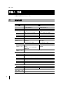
有寿命部品と消耗品について
• 本製品には、有寿命部品が含まれています。有寿命部品は、使用時間の経過に伴って摩
耗、劣化などが進行し、動作が不安定になる場合があります。
本製品をより長く安定してお使いいただくために、一定の期間で交換してください。
J
• 有寿命部品の交換時期の目安は、使用頻度や使用環境などにより異なりますが、1 日約 8 時
間のご使用で約 5 年です。なお、この期間はあくまでも目安であり、この期間内に故障し
ないことをお約束するものではありません。
また、長時間連続使用や高温環境に設置など、ご使用状態によっては、この目安の期間
よりも早期に部品交換が必要となる場合があります。
• 主な有寿命部品は以下のとおりです。
ハードディスクドライブ、ソリッドステートドライブ(SSD)、CFast、ファン、電池
PFU Limited Proprietary & Confidential
v
清掃について
本製品を清掃する場合、布に水(または薄めた中性洗剤)を含ませ、固く絞ってからふいて
ください。その際、装置内に水が入らないようにご注意ください。
グリーン製品について
弊社の厳しい環境評価基準をクリアした、地球に優しい、環境への負荷の少ない「グリーン
製品」です。
主な特長
• 小型/省資源化
• 節電機能保有
• 再資源化率が高い
エネルギー消費について
• 電源スイッチ「オフ」状態での消費電力:1.3W 以下
電源スイッチ「オフ」状態のエネルギー消費は、本製品の DC 電源ケーブルを抜くことに
より、抑えることができます。
• 動作時消費電力:約 77W(PD-AR21AAAAE の場合)/約 64W(PD-AR21ACAAE の場合)
LAN インタフェース機能を使用する場合の留意事項
本製品の LAN インタフェースを、直接、電気通信事業者の回線(例:インターネットサービ
スプロバイダが提供している通信網サービスなど)に接続するためには、電気通信事業法に
よる技術基準適合認定の取得、または電気通信事業者の検査による許可が必要ですのでご留
意ください。
vi
PFU Limited Proprietary & Confidential
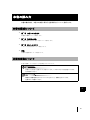
1
本書の読み方
本書の構成内容、本書での表記に関する注意事項などについて説明します。
2
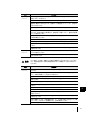
本書の構成について
• 第 1 章 お使いになる前に
本製品の概要について説明します。
• 第 2 章 取り扱い方法
本製品の基本的な取り扱い方法について説明します。
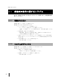
3
• 第 3 章 困ったときには
トラブルの対処方法について説明します。
• 付録
4
仕様や留意事項について説明します。
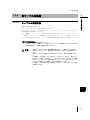
本書の表記について
本書で使用している記号とその意味を以下に示します。
5
お使いになるときに注意していただきたいことや、してはいけないことを記述しています。
必ずお読みください。
6
関連する情報が記載されているマニュアルを示したり、参照先を示しています。
必要に応じてお読みください。
J
PFU Limited Proprietary & Confidential
vii
略称
本書では、以下の製品名称について省略して表記する場合がありますので、ご了承ください。
製品名称
組込みコンピュータ AR2100 モデル 100J
viii
PFU Limited Proprietary & Confidential
略称
本製品、本体
目次
第1章
1
お使いになる前に ......................................... 1
1.1
機能と特長 ............................................................................ 2
1.2
作業の流れ ............................................................................ 3
1.3
梱包物の確認......................................................................... 4
1.4
各部の名称と働き ................................................................. 5
1.4.1
1.4.2
1.5
3
本製品の設置......................................................................... 7
1.5.1
1.5.2
1.5.3
第2章
本体前面............................................................................... 5
本体側面............................................................................... 6
2
設置条件............................................................................... 7
各ケーブルの接続 .............................................................. 13
DC 電源の使用について..................................................... 17
4
取り扱い方法 .............................................. 19
2.1
電源の入れ方/切り方 ........................................................ 20
2.1.1
2.1.2
2.2
CFast カードの使い方 ........................................................ 23
2.2.1
2.2.2
2.2.3
2.3
CFast カードの取り付け手順............................................. 23
CFast カードの取り出し手順............................................. 25
ブートデバイスの設定について......................................... 26
トップカバーの取り外し/取り付け................................... 27
2.3.1
2.3.2
2.4
電源を入れる ..................................................................... 21
電源を切る ......................................................................... 22
トップカバーの取り外し手順 ............................................ 27
トップカバーの取り付け手順 ............................................ 28
拡張カードの取り付け/取り外し ...................................... 29
2.4.1
2.4.2
2.4.3
取り付ける前に .................................................................. 29
拡張カードの取り付け手順 ................................................ 30
拡張カードの取り外し手順 ................................................ 32
PFU Limited Proprietary & Confidential
J
ix
第3章
困ったときには .......................................... 33
3.1
起動時の動作に関するトラブル.......................................... 34
3.1.1
3.1.2
3.2
電源が入らない .................................................................. 34
システムがダウンする ....................................................... 34
担当営業に連絡するときは................................................. 35
付録 ............................................................................ 37
付録 A 仕様 ................................................................................. 38
A.1
製品仕様............................................................................. 38
付録 B 装置ラベルについて ........................................................ 40
B.1
B.2
貼付場所............................................................................. 40
ラベルの種類 ..................................................................... 41
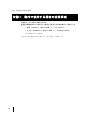
付録 C カリフォルニア州法
「過塩素酸塩の取り扱いに関する規制」について ...........42
C.1
C.2
C.3
C.4
規制対象.............................................................................
適用範囲.............................................................................
過塩素酸塩物質の管理実践要求事項の表示.......................
必要な対応 .........................................................................
42
42
42
42
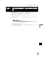
付録 D 他社製周辺機器をご利用の際の注意事項........................ 43
付録 E 海外で使用する場合の注意事項 ...................................... 44
x
PFU Limited Proprietary & Confidential
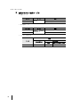
第1章
お使いになる前に
この章では、本製品の概要と操作の流れについて説
明します。
1.1
機能と特長 ........................................................................................ 2
1.2
作業の流れ ........................................................................................ 3
1.3
梱包物の確認 .................................................................................... 4
1.4
各部の名称と働き ............................................................................. 5
1.5
本製品の設置 .................................................................................... 7
第1章
お使いになる前に
1.1
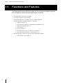
機能と特長
本製品は、多種多様な用途に適した小型の組込みコンピュータです。
以下に概要を示します。
• インテル ® AtomTM プロセッサーを搭載しています。
• メモリを最大 8GB まで搭載できます。
• 2.5 インチのハードディスク、または SSD を 1 台搭載できます(オプション)。
• 前面に以下のコネクタを装備しています。
• USB2.0 コネクタ × 4
• LAN コネクタ(10BASE-T/100BASE-TX/1000BASE-T)× 2
• シリアルコネクタ(RS-232C)× 2
• VGA コネクタ ×1
• DVI-D コネクタ ×1
• PS/2 キーボードコネクタ × 1、マウスコネクタ × 1
• オーディオコネクタ LINE IN × 1、LINE OUT × 1
• 側面に以下のスロットを装備しています。
• CFast カードスロット(シリアル ATA)× 1
2
PFU Limited Proprietary & Confidential
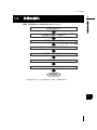
1.2
1.2
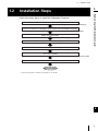
作業の流れ
1
作業の流れ
Ვໟ≀ࢆ☜ㄆࡍࡿ
→ࠕ1.3 Ვໟ≀ࡢ☜ㄆࠖ
お使いになる前に
開梱から運用開始までの作業の流れを次に示します。
2
タ⨨ሙᡤࢆ☜ㄆࡋࠊタ⨨ࡍࡿ
→ࠕ1.5.1ࠉタ⨨᮲௳ࠖ
࿘㎶ᶵჾࢆྲྀࡾࡅࡿ
→ࠕ1.5.2ࠉྛࢣ࣮ࣈࣝࡢ᥋⥆ࠖ
3
࿘㎶ᶵჾࡢྲྀࡾࡅ≧ែࢆ☜ㄆࡍࡿ
DC㟁※ࢣ࣮ࣈࣝࢆ᥋⥆ࡍࡿ
→ࠕ1.5.2ࠉྛࢣ࣮ࣈࣝࡢ᥋⥆ࠖ
4
㟁※ࢆධࢀࡿ
→ࠕ2.1 㟁※ࡢධࢀ᪉㸭ษࡾ᪉ࠖ
OSࢆࣥࢫࢺ࣮ࣝࡍࡿ㸦㸧
5
㐠⏝㛤ጞ
*1 ᘢ♫ᥦ౪ࡢOS ࢜ࣉࢩࣙࣥࢆ㑅ᢥࡉࢀ࡚࠸ࡿሙྜࠊᮏసᴗࡣせ࡛ࡍࠋ
6
J
PFU Limited Proprietary & Confidential
3
第1章
お使いになる前に
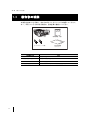
1.3
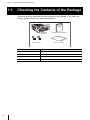
梱包物の確認
本製品をお使いになる前に、次のものがすべてそろっているか確認してください。
万一、不足しているものがある場合は、担当営業に連絡してください。
ᮏయ
ྲྀᢅㄝ᫂᭩㸦ᮏ᭩㸧
ࢣ࣮ࣈࣝࢡࣛࣥࣉ㸦ಶ㸧
OS⏝チㅙ᭩
㸦࢜ࣉࢩࣙࣥ㸧
添付品の名称
内容
本体
本製品の装置本体です。
取扱説明書(本書)
本製品の取扱説明書です。
ケーブルクランプ
ケーブル固定用のクランプです。
OS 使用許諾書(オプション) プレインストールされた OS の使用許諾書です。
4
PFU Limited Proprietary & Confidential
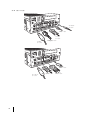
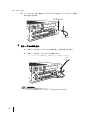
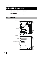
1.4
1.4
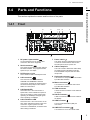
各部の名称と働き
1
各部の名称と働き
お使いになる前に
本製品の各部の名称とその働きは、以下のとおりです。
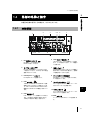
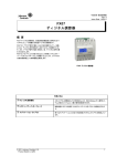
1.4.1
2
本体前面
2
1
3
4 5
6
7
3
9 10
11
12
13
14 1516 17
4
8
1
DC 電源入力コネクタ
6
LAN コネクタ 1、2 とも同様のランプがあり
ます。リンク確立中に点灯し、データ転送中
に点滅します。
DC 電源ケーブルを接続します。
DC24V に対応しています。
2
シリアルコネクタ
7
RS-232C 仕様準拠のシリアルコネクタが 2
つ用意されています。115.2kbps までの転送
速度に対応しています。
3
PCI Express × 1 スロット
LAN コネクタ
10BASE-T/100BASE-TX/1000BASE-T 仕様
準拠の LAN コネクタが 2 つ用意されていま
す。PXE(Preboot eXecution Environment)
機能および Wake On LAN 機能に対応してい
ます。
5
LAN 速度ランプ
LAN コネクタ 1、2 とも同様のランプがあり
ます。1000Mbps で動作中に橙色に点灯し、
100Mbps で動作中に緑色に点灯します。
5
電源スイッチ
本製品の電源を入れたり切ったりする場合に
使用します。5 秒以上押し続けると、強制的
に電源を切ることができます。
8
PCI Express カードを搭載します。
4
LAN リンク/動作ランプ
ケーブルクランプ固定用穴
添付品のケーブルクランプを取り付けます。
2 つ用意されています。
9
6
キーボードコネクタ
6 ピン小型 DIN の PS/2 インターフェースに
対応したキーボードを接続します。
J
10 マウスコネクタ
6 ピン小型 DIN の PS/2 インターフェースに
対応したマウスを接続します。
11 VGA コネクタ
ディスプレイ用の VGA ケーブルを接続しま
す。
PFU Limited Proprietary & Confidential
5
第1章
お使いになる前に
15 LINE IN コネクタ
12 DVI-D コネクタ
オーディオケーブル(ライン入力用)を接続
します。
ディスプレイ用の DVI ケーブルを接続しま
す。
16 ハードディスクアクセスランプ
13 USB コネクタ
ハードディスクにデータを書き込んだり、
ハードディスクからデータを読み込んだりし
ているときに、緑色に点灯します。
USB(Universal Serial Bus)2.0 規格のコネ
クタが 4 つ用意されています。
17 電源ランプ
14 LINE OUT コネクタ
本製品に電源が入っているときに、緑色に点
灯します。
オーディオケーブル(ライン出力用)を接続
します。
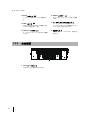
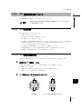
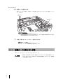
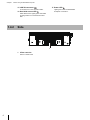
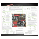
1.4.2
本体側面
1
1
CFast カードスロット
CFast カードを 1 枚取り付けできます。
6
PFU Limited Proprietary & Confidential
1.5
1.5
本製品の設置
1
本製品の設置
警告
1.5.1
本製品の設置、電源工事は必ず教育を受けた作業員が行ってください。感電・火
災・故障の原因となります。
お使いになる前に
本製品の設置条件や設置手順について説明します。
2
設置条件
3
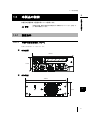
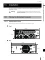
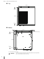
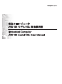
1.5.1.1
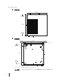
外形寸法の詳細について
外形寸法の詳細について次に示します。
本体前面
4
195mm
5
74mm
本体背面
6
195mm
J
74mm
PFU Limited Proprietary & Confidential
7
第1章
お使いになる前に
本体上面
195mm
⫼㠃ഃ
220mm
๓㠃ഃ
本体底面
12.5mm
170mm
12.5mm
M3ࢱࢵࣉ × 4㸦*1㸧
28mm
⫼㠃ഃ
170mm
๓㠃ഃ
22mm
*1 ネジ入り込みの深さは、筐体表面より 4mm 以内です。
注意
8
4mm 以上ネジを入れないでください。装置固定不良(ガタつき)の原因となりま
す。
PFU Limited Proprietary & Confidential
1.5
本製品の設置
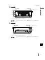
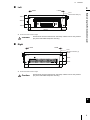
本体左側面
1
⫼㠃ഃ
๓㠃ഃ
18mm
38mm
2
18mm
16mm
180mm
24mm
*1 ネジ入り込みの深さは、筐体表面より 4mm 以内です。
注意
お使いになる前に
M3ࢱࢵࣉ × 4㸦*1㸧
4mm 以上ネジを入れないでください。装置固定不良(ガタつき)の原因となりま
す。
3
本体右側面
๓㠃ഃ
⫼㠃ഃ
M3ࢱࢵࣉ × 4㸦*1㸧
4
18mm
38mm
18mm
24mm
180mm
5
16mm
*1 ネジ入り込みの深さは、筐体表面より 4mm 以内です。
注意
4mm 以上ネジを入れないでください。装置固定不良(ガタつき)の原因となりま
す。
6
J
PFU Limited Proprietary & Confidential
9
第1章
お使いになる前に
1.5.1.2
設置スペース
設置する際は、吸排気エリアとして、以下のスペースを確保してください。
• 横置きの場合
100mm௨ୖ
100mm௨ୖ
50mm௨ୖ
50mm௨ୖ
100mm௨ୖ
• 縦置きの場合(右側面を下側)
100mm௨ୖ
100mm௨ୖ
100mm௨ୖ
50mm௨ୖ
20mm௨ୖ㸦*1㸧
*1 吸排気口に対して、20mm 以上のスペースを確保してください。
10
警告
上記以外の方向で設置することはできません。
上記以外で設置する場合は、担当営業にご相談ください。
注意
完全密閉された空間に、本製品を設置しないでください。長時間の使用による温度
上昇で製品の動作不良などのトラブルを引き起こす可能性があります。
PFU Limited Proprietary & Confidential
1.5
1.5.1.3
本製品の設置
1
吸排気について
注意
本製品の吸排気口の周辺には、十分な空間を確保してください。吸排気のための十
分な空間がない場合、本体内の温度が非常に高くなり、装置が故障することがあり
ます。
お使いになる前に
本製品の空気吸排気口を、以下に示します。
2
྾Ẽཱྀ
3
4
5
྾Ẽཱྀ
6
J
PFU Limited Proprietary & Confidential
11
第1章
お使いになる前に
1.5.1.4
設置環境
以下に本製品の設置条件を示します。
次に記載する条件を守ってご使用ください。
条件を守らずに使用すると、本製品の故障の原因となるおそれがあります。
諸元
温度
動作時
湿度
条件
ハードディスク搭載時
5 ~ 40°C
ハードディスク非搭載時
0 ~ 50°C
保存時
-20 ~ 60°C
動作時
5 ~ 90%RH
保存時
5 ~ 95%RH
温度勾配
15°C/Hr 以下(結露しないこと)
湿度勾配
30%/Day 以下
振動
0.5G
衝撃
10G
複数の USB デバイスが相互に干渉する場合は、耐振動性・耐衝撃性を保証できません。USB
ケーブルを介して、USB デバイスを接続してください。
「1.5.2 各ケーブルの接続」
(P.13)
12
PFU Limited Proprietary & Confidential
1.5
各ケーブルの接続
1.5.2.1
ケーブルの接続方法
1
本製品に周辺機器を接続します。
各ケーブルは、次のように本体に接続してください。
シリアルケーブル、ディスプレイ用ケーブル、キーボードケーブル、マウスケーブルは、本
体の電源投入前に接続してください。
なお、本製品は、ケーブルクランプを取り付ける穴を用意しております。オーディオケーブ
ル、USB ケーブルなどのロック機構がないコネクタにケーブルクランプを使用することによ
りコネクタ抜けを防止できます。ケーブルの接続状況、配線方向に合わせて使用してくださ
い。
お使いになる前に
1.5.2
本製品の設置
2
3
本体にディスプレイを接続していない状態またはディスプレイの電源が投入されていない状態で
本体の電源を投入した場合、誤動作の原因となります。
注意
•
•
•
•
接続するときは、本体および周辺機器の電源を切り、DC 電源ケーブルを本体から
取り外してください(「2.1 電源の入れ方/切り方」(P.20))。感電の原因となり
ます。
濡れた手でスイッチや電源プラグに触れないでください。感電のおそれがありま
す。
DC 電源ケーブルを濡らしたり、傷つけたり、加工したり、結んだり、束ねたり、
巻きつけたり、重いものを載せたり、ドアなどにはさんだり、落下させたり、衝撃
を与えたり、引っ張ったり、無理に曲げたり、ねじったり、加熱したりしないでく
ださい。DC 電源ケーブルを傷め、火災・感電の原因になります。
DC 電源ケーブルの電源プラグに金属を近づけないでください。感電・火災・故障
の原因となります。
4
5
6
J
PFU Limited Proprietary & Confidential
13
第1章
お使いになる前に
オーディオ
ケーブル
LANケーブル
シリアル
ケーブル
マウス
ケーブル
DC電源ケーブル
USBケーブル
キーボード
ケーブル
14
PFU Limited Proprietary & Confidential
VGAケーブル
DVIケーブル
1.5
1.5.2.2
本製品の設置
1
ケーブルの固定方法
にクランプで固定してください。
注意
ケーブルクランプを使用しない場合、ケーブルクランプ固定用穴に物を入れないで
ください。故障の原因となります。
お使いになる前に
ケーブルクランプを使用すれば、USB ケーブルなどのロック機構をもたないコネクタが抜け
るのを防止できます。
以下に、USB ケーブルを固定する方法を説明します。コネクタにストレスが加わらないよう
2
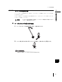
ケーブルクランプの取り付け方法
1 ケーブルクランプの先端を根元に通し、輪を作成します。
3
4
2 ロック部を矢印の方向に押してロックを解除し、輪の大きさを調整します。
5
ࣟࢵࢡ㒊
輪が小さすぎると、ケーブルが入らないおそれがあります。
6
J
PFU Limited Proprietary & Confidential
15
第1章
お使いになる前に
3 ケーブルクランプを、輪が下にくるようにした状態で、ケーブルクランプ固定
用穴に差し込みます。
ࢣ࣮ࣈࣝ
ࢡࣛࣥࣉᅛᐃ⏝✰
ࢣ࣮ࣈࣝࢡࣛࣥࣉ
各ケーブルの固定方法
1
USB ケーブルをケーブルクランプの輪に通し、本体に取り付けます。
2
USB ケーブルをケーブルクランプに固定します。
ケーブルクランプの先端を引き、輪を小さくして固定してください。
ᘬࡃ
ケーブルクランプの輪が大きいと、USB ケーブルが抜けるおそれがあります。
16
PFU Limited Proprietary & Confidential
1.5
1.5.3
本製品の設置
1
DC 電源の使用について
警告
1.5.3.1
本製品の設置、電源工事は必ず教育を受けた作業員が行ってください。感電・火
災・故障の原因となります。
お使いになる前に
DC 電源を使用する場合は、以下の条件に従ってください。
2
DC 電源仕様
DC 電源の仕様は、以下のとおりです。
• 定格入力電圧は、24V です。
3
• DC 電源は、AC 電源から絶縁させてください。
• DC 電源は、正しく接地してください。
• DC 電源は、情報処理装置 (IEC60950-1) の電源として認定を受けたもの、かつ、8.0A 未満
に制限された電流であり、危険エネルギー(IEC60950-1 で定義された危険エネルギーレ
ベル)のない SELV 回路から受ける必要があります。
• DC 電源は、緊急電源切断スイッチがあるものを使用してください。
緊急電源切断スイッチがない電源を使用する場合は、遮断器を入れてください。
遮断器は、電源容量が 10A 以上のものを使用してください。
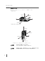
1.5.3.2
DC 電源の接続方法
DC 電源と本製品を接続するための DC 電源ケーブルの組み立てについて説明します。
4
5
使用する DC 電源ケーブル
本製品の DC 電源ケーブルは、以下の条件に適合したものを使用してください。
• 導線の太さ :AWG18
• 絶縁材質 :使用温度の定格 80 ℃以上で、防炎かつ難燃であること
6
• 適合ケーブル:UL1007 または CSA TR-64
DC 電源入力コネクタのピンアサイン
DC 24V
DC 24V
J
GND
GND
㸺⨨ഃ㸼
㸺ࢣ࣮ࣈࣝഃ㸦᥋⥆ഃࡽぢࡿ㸧㸼
PFU Limited Proprietary & Confidential
17
第1章
お使いになる前に
推奨コネクタ/推奨ケーブル
• 電源コネクタ
コネクタ
ハウジング
コンタクト
メーカ
MOLEX
型番
5557-04R
5556PBTL または 5556PBT
• DC 電源ケーブル
ケーブル
DC24V ケーブル
GND ケーブル
メーカ
型番
古河電工、日立電線、 UL1007、AWG18、Yellow
昭和電線など
UL1007、AWG18、Black
• コンタクト圧着工具
型名
メーカ
自動圧着機
手動圧着工具
本体
MOLEX
18
57026-5000
PFU Limited Proprietary & Confidential
57275-4000
モジュラークリンプダイ
57022-3000
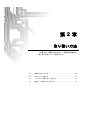
第2章
取り扱い方法
この章では、電源の入れ方など、本製品の基本的な
取り扱い方法について説明します。
2.1
電源の入れ方/切り方 .................................................................... 20
2.2
CFast カードの使い方 .................................................................... 23
2.3
トップカバーの取り外し/取り付け .............................................. 27
2.4
拡張カードの取り付け/取り外し .................................................. 29
第2章
取り扱い方法
2.1
電源の入れ方/切り方
本製品の電源を入れたり切ったりする方法について、説明します。
注意
•
•
•
•
電源を入れたまま、持ち運んだり、衝撃や振動を与えたりしないでください。感
電・火災・故障、およびデータを消失する原因となります。
本製品が結露している場合は、結露がなくなってから電源を入れてください。故
障、感電の原因となります。
この章で示す操作手順で、電源を入れたり切ったりしてください。操作手順に反す
ると、データが破壊されるおそれがあります。
電源スイッチは棒などで押さないでください。スイッチが破損し故障の原因となり
ます。
緊急時の電源切断方法について、説明します。
警告
•
•
•
20
設置場所の緊急電源遮断スイッチがどこにあるか確認し、万一、装置から発熱・発
煙・異臭が発生したときは、すぐに本体の電源を切断してください。
DC 電源に緊急電源切断スイッチがある場合は、そのスイッチで電源を切断してく
ださい。
DC 電源に緊急電源切断スイッチがない場合は、DC 電源に対応している電源プラグ
をコンセントから抜くか、または配電盤上で DC 電源に対応しているブレーカーを
切断してください。
PFU Limited Proprietary & Confidential
2.1
2.1.1
電源の入れ方/切り方
1
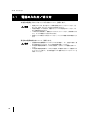
電源を入れる
1 ディスプレイや周辺機器の電源を入れます。
2 装置前面の電源スイッチを押します。
電源が入ると、電源ランプが緑色に点灯し、本製品は「POST(Power On Self Test: パ
ワーオンセルフテスト)」を行います。
㟁※ࢫࢵࢳ
取り扱い方法
㟁※ࣛࣥࣉ
⥳ⰍⅬⅉ
2
3
4
POST 実行中に電源を切らないでください。誤動作の原因となります。
注意
電源スイッチは棒などで押さないでください。スイッチが破損し故障の原因となり
ます。
5
6
J
PFU Limited Proprietary & Confidential
21
第2章
取り扱い方法
2.1.2
電源を切る
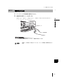
1 USB コネクタに CD-ROM ドライブや DVD-ROM ドライブを接続している場合
は、ドライブに媒体が入っていないことを確認します。
媒体が入っている場合は、取り出してください。
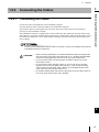
2 OS を終了します。
OS の終了後、本体の電源が自動的に切れます。
OS を終了しても電源が切れない場合は、本体前面の電源スイッチを 5 秒以上押し続け
てください。
㟁※ࣛࣥࣉ
ᾘⅉ
㟁※ࢫࢵࢳ
注意
電源スイッチは棒などで押さないでください。スイッチが破損し故障の原因となり
ます。
3 ディスプレイや周辺機器の電源を切ります。
22
PFU Limited Proprietary & Confidential
2.2
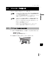
2.2
CFast カードの使い方
CFast カードの使い方
1
CFast カードの取り付けや取り出しについて、説明します。
注意
•
CFast カードの取り付けや取り出しを行う場合は、本体および周辺機器の電源を切
り、DC 電源ケーブルを本体から取り外してください。感電や故障の原因となりま
す(
「2.1 電源の入れ方/切り方」(P.20) )。
2
•
CFast カードは、装置の使用直後に高温になっている場合があります。しばらく時
間を置いてから取り外してください。やけどなどの原因になります。
•
•
CFast カードは、人体から発生する静電気によって損傷を受ける場合があります。
取り扱う前に、身近な金属部分に触れるなどして人体の静電気を放電してくださ
い。
CFast カードは、温度の高い場所や、直射日光のあたる場所に置かないでくださ
い。
CFast カードに強い衝撃を与えないでください。
取り扱い方法
警告
•
CFast カードに重い物を載せないでください。
•
CFast カードにコーヒーなどの液体がかからないように、注意してください。
•
CFast カードを保管する場合は、必ず専用のケースに入れてください。
•
3
4
2.2.1
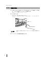
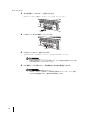
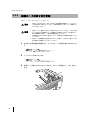
CFast カードの取り付け手順
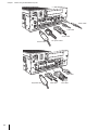
1 本体および周辺機器の電源を切り、DC 電源ケーブルを本体から取り外します。
5
「2.1 電源の入れ方/切り方」(P.20)
2 本体側面のネジを緩め、CFast カードのカバーを取り外します。
6
࢝ࣂ࣮
PFU Limited Proprietary & Confidential
J
23
第2章
取り扱い方法
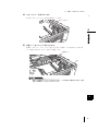
3 向きを確認し、CFast カードを取り付けます。
CFast カードの向きを確認し、奥までしっかりと差し込んでください。
4 LOCK レバーを右に移動し、ロックします。
LOCKࣞࣂ࣮
5 CFast カードのカバーを取り付けます。
手順 2 で取り外した CFast カードのカバーを元通りに取り付けてください。
指定以上の締め付けトルクでネジ止めをすると、ネジ穴が壊れる場合があります。適正
なネジの締め付けトルクは、0.49N・m です。
6 DC 電源ケーブルを取り付け、周辺機器および本体の電源を入れます。
CFast カードのカバーを取り外したまま本製品を使用しないでください。カバーを取り
付けずに本製品を使用すると、誤動作や故障の原因となります。
24
PFU Limited Proprietary & Confidential
2.2
2.2.2
CFast カードの使い方
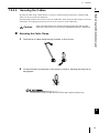
CFast カードの取り出し手順
1
1 本体および周辺機器の電源を切り、DC 電源ケーブルを本体から取り外します。
「2.1 電源の入れ方/切り方」(P.20)
取り扱い方法
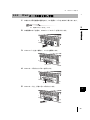
2 本体側面のネジを緩め、CFast カードのカバーを取り外します。
2
3
࢝ࣂ࣮
3 LOCK レバーを左へ移動し、ロックを解除します。
LOCKࣞࣂ࣮
4
5
4 CFast カード取り出しボタンを押します。
6
取り出しボタン
5 CFast カードを、手前に引いて取り出します。
PFU Limited Proprietary & Confidential
J
25
第2章
取り扱い方法
6 手順 2 で取り外したカバーを取り付けます。
CFast カードのカバーを取り外したまま本製品を使用しないでください。カバーを取り
付けずに本製品を使用すると、誤動作や故障の原因となります。
2.2.3
ブートデバイスの設定について
ブートデバイスの設定について説明します。
CFast カードとハードディスク(または SSD)を同時搭載した状態では、OS がインストール
されているデバイスからブートされます。
CFast カードとハードディスク(または SSD)の両方に OS がインストールされている場合
は、ブートデバイスの優先順位を適切に設定する必要があります。
本設定は、「Boot Priority Order」(セットアップの Boot メニュー)で変更できます。
• 『機能説明書』の「セットアップ」
• 『機能説明書』の「機能説明」
26
PFU Limited Proprietary & Confidential
2.3
2.3
トップカバーの取り外し/取り付け
トップカバーの取り外し/取り付け
1
トップカバーの取り外し/取り付け方法について説明します。
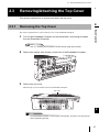
2.3.1
トップカバーの取り外し手順
1 本体および周辺装置の電源を切り、すべてのケーブル類を本体から取り外しま
す。
取り扱い方法
本体のトップカバーの取り外し手順を説明します。
2
3
「2.1 電源の入れ方/切り方」(P.20)
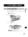
2 前面のネジ(2 本)を外します。
4
5
3 トップカバーを取り外します。
トップカバーを装置前面にスライドさせてください。
6
ࢺࢵࣉ࢝ࣂ࣮
J
本体が縦置きになっている場合は、図のように横置きにしてから作業してください。
PFU Limited Proprietary & Confidential
27
第2章
取り扱い方法
2.3.2
トップカバーの取り付け手順
トップカバーの取り付けは、取り外しと逆の手順で行います。
注意
トップカバーを取り付けずに本製品を使用しないでください。
火災のおそれがあります。
指定以上の締め付けトルクでネジ止めをすると、ネジ穴が壊れる場合があります。適正なネジの
締め付けトルクは、0.49N・m です。
28
PFU Limited Proprietary & Confidential
2.4
2.4
拡張カードの取り付け/取り外し
拡張カードの取り付け/取り外し
1
拡張カードの取り付け/取り外し方法について説明します。
2.4.1
2
取り付ける前に
拡張カードの取り付け/取り外しの際は、本体および周辺装置の電源を切り、十分
に時間をおいてから作業を行ってください。
電源を切った直後は本体内部が高温になっており、やけどのおそれがあります。
拡張カードの搭載場所と拡張カードスロットの仕様について説明します。
拡張カードスロット
PCI Express x1 スロット
取り扱い方法
注意
3
サポート
PCI Express x1 カード
4
本製品に搭載する拡張カードの消費電力は、25W 以下としてください。
他社製の拡張カードをご利用になる際の注意事項については、
「付録 D 他社製周辺機器をご利用
の際の注意事項」(P.43)を参照してください。
5
6
J
PFU Limited Proprietary & Confidential
29
第2章
取り扱い方法
2.4.2
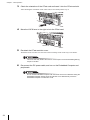
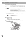
拡張カードの取り付け手順
拡張カードの取り付け方法について説明します。
拡張カードを取り付けるときは、本体および周辺装置の電源を切り、すべてのケー
ブル類を本体から取り外してください。感電の原因となります(「2.1 電源の入れ
方/切り方」
(P.20))
。
警告
注意
•
•
•
拡張カードは、基板や半田づけした部分がむきだしになっています。これらの部分
は、人体に発生する静電気によって損傷を受ける場合があります。取り扱う前に、
本体の金属部分に触れて、人体の静電気を放電してください。
基板表面や半田づけの部分に触れないように、金具の部分や基板の縁を持つように
してください。
拡張カードは静電気の影響を受けやすいので、導電マットなどの上に置くか、取り
扱う直前まで梱包袋に入れておいてください。
1 本体および周辺装置の電源を切り、すべてのケーブル類を本体から取り外しま
す。
「2.1 電源の入れ方/切り方」
(P.20)
2 トップカバーを取り外します。
「2.3.1 トップカバーの取り外し手順」(P.27)
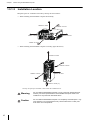
3 拡張カードを取り付けるスロットのスロットカバーの固定ネジ(1 本)を外し
ます。
ࢿࢪ
30
PFU Limited Proprietary & Confidential
2.4
拡張カードの取り付け/取り外し
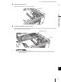
4 スロットカバーを取り外します。
1
取り外したスロットカバーは大切に保管してください。
ࢫࣟࢵࢺ࢝ࣂ࣮
2
取り扱い方法
3
5 拡張カードをスロットに取り付けます。
拡張カードをスロットにしっかりと差し込みます。拡張カードは下図のように取り付
け、手順 3 で取り外したネジ(1 本)で固定します。
ᣑᙇ࣮࢝ࢻ
4
ࢿࢪ
5
指定以上の締め付けトルクでネジ止めをすると、ネジ穴が壊れる場合があります。適正
なネジの締め付けトルクは、0.49N・m です。
6
J
PFU Limited Proprietary & Confidential
31
第2章
取り扱い方法
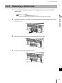
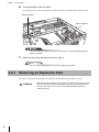
6 拡張カードを固定します。
固定ガードのネジを緩め、拡張カードの端面にあたるまでスライドさせて固定してくだ
さい(2 箇所)。
ᅛᐃ࣮࢞ࢻ
ᅛᐃ࣮࢞ࢻ
指定以上の締め付けトルクでネジ止めをすると、ネジ穴が壊れる場合があります。適正
なネジの締め付けトルクは、0.49N・m です。
7 手順 2 で取り外したトップカバーを取り付けます。
「2.3 トップカバーの取り外し/取り付け」
(P.27)
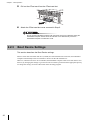
2.4.3
拡張カードの取り外し手順
拡張カードの取り外しは、取り付けと逆の手順で行います。
注意
32
拡張カードを取り外したあとは、保管していたスロットカバーを必ず取り付けてく
ださい。スロットカバーを取り外したまま本製品を使用しないでください。誤動作
や故障の原因となります。
PFU Limited Proprietary & Confidential
第3章
困ったときには
この章では、本製品を使用していてトラブルが発生
した場合の対処方法について、説明します。
原因の特定ができない場合や現象が解消されない場
合は、担当営業に連絡してください。
3.1
起動時の動作に関するトラブル ..................................................... 34
3.2
担当営業に連絡するときは ............................................................ 35
第3章
困ったときには
3.1
起動時の動作に関するトラブル
以下に、発生すると考えられる主なトラブルについて説明します。状況整理時の参
考にしてください。
3.1.1
電源が入らない
【現象】電源スイッチを押しても電源が入らない。
【原因】以下のどれかの原因が考えられます。
• ケーブルが抜けている、または断線している。
→ケーブルが正しく接続されているかを確認してください。
断線している場合は、ケーブルの交換が必要です。担当営業に連絡してくださ
い。
• 電源切断後、再投入までの時間が短い。
→電源切断後、再投入までの時間が短い場合、電源が入らない場合があります。
10 秒以上間隔を空けて電源を入れてください。
• 接続しているディスプレイまたはディスプレイ切替器によっては、本体の電源を
投入したあとで、ディスプレイまたはディスプレイ切替器の電源を投入する必要
があります。
• 本体の故障などのハードウェア障害が発生した。
→担当営業に連絡してください。
3.1.2
システムがダウンする
【現象】USB デバイスを接続している場合に、システムがダウンする。
【原因】以下のどれかの原因が考えられます。
• USB デバイスの故障または短絡している。
→ USB デバイスを取り外して起動を確認してください。
• 起動後に、正常なデバイスを接続しても認識しない。
→担当営業に連絡してください。
34
PFU Limited Proprietary & Confidential
3.2
3.2
担当営業に連絡するときは
担当営業に連絡するときは
1
どうしても異常の原因がわからないときは、担当営業に連絡してください。
事前に次のことを確認して、担当営業に伝えられるようにしておいてください。
2
• 本製品の型名と製造番号
• 本製品に取り付けているオプションの種類
• セットアップの工場出荷設定値からの変更箇所
• ご使用の OS
• 現象(何をしているときに何が起きたか、画面に表示されたメッセージなど)
3
• 本製品の設置環境や接続している機器
• 各種ランプの状態
困ったときには
4
5
J
PFU Limited Proprietary & Confidential
35
第3章
困ったときには
このページは空白です。
36
PFU Limited Proprietary & Confidential
付録
この章では、本製品の仕様や留意事項について説明
します。
付録 A
仕様 ................................................................................................ 38
付録 B
装置ラベルについて ....................................................................... 40
付録 C
カリフォルニア州法 「過塩素酸塩の取り扱いに関する規制」 につい
て .................................................................................................... 42
付録 D
他社製周辺機器をご利用の際の注意事項 ....................................... 43
付録 E
海外で使用する場合の注意事項 ..................................................... 44
付録 A
仕様
付録 A 仕様
本製品の仕様は以下のとおりです。
A.1
製品仕様
項目
概要
品名
組込みコンピュータ AR2100 モデル 100J
型名
PD-AR21AAAAE(-**)
入力電源
DC 入力:24V±5%
CPU(標準搭載)
インテル ®
Atom
™
PD-AR21ACAAE(-**)
インテル ®
Atom™ プロセッサー E3825
プロセッサー E3845
動作周波数
1.91GHz
1.33GHz
コア数 / スレッド
4 コア /4 スレッド
2 コア /2 スレッド
キャッシュ
L2-2MB
L2-1MB
-
チップセット
メモリ
(必須オプション)
DDR3L-1333 Unbuffered SO-DIMM
(ECC あり)
2GB/4GB/8GB から選択
DDR3L-1066 Unbuffered SO-DIMM
(ECC あり)
2GB/4GB/8GB から選択
ストレージ
ハードディスクベイ 2.5 インチ シリアル ATA HDD × 1、
(選択オプション) または
2.5 インチ シリアル ATA SSD × 1
を搭載可能
CFast カード
(選択オプション)
2.5 インチ シリアル ATA SSD × 1 を
搭載可能
CFast カード(シリアル ATA)× 1 を搭載可能
インターフェース
ディスプレイ
VGA× 1、DVI-D × 1
LAN
1000BASE-T/100BASE-TX/10BASE-T × 2(PXE(Preboot eXecution
Environment)、Wake On LAN 対応)
シリアル
RS-232C × 2
キーボード / マウス
PS/2 × 各 1
USB
USB 2.0 × 4
オーディオ
LINE IN × 1、LINE OUT × 1
拡張インターフェース
PCI Express × 1
ファン
PCI Express2.0(5Gbps)1 スロット
ファンあり
ファンレス
外形寸法
195mm × 220mm × 74mm(突起物含まず)
(横幅 × 奥行き × 高さ)
質量
38
約 2.5kg
PFU Limited Proprietary & Confidential
付録 A
項目
仕様
概要
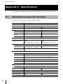
最大消費電力
77W
省電力モード(*1)
S4
64W
1
*1 省電力モードの機能は以下のとおりです。
S0 :
システムがオンの状態で、完全に機能している状態です。
S1 :
CPU クロックは停止していますが、メモリは電源が入っており更新されていま
す。
S2 :
S1 と同様ですが、CPU の電源がオフとなります。
S3 :
スリープ状態。ほとんどのコンポーネントがシャットダウンされます。メモリは
引き続き稼働します
S4 :
休止状態。メモリの内容がディスクドライブにスワップされ、システムのウェイ
クアップ時にメモリに再ロードされます。
S5 :
システムがオフで、電源投入に必要な電流のみ流れている状態です。
2
3
付録
4
5
6
J
PFU Limited Proprietary & Confidential
39
付録 B
装置ラベルについて
付録 B 装置ラベルについて
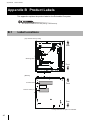
本製品に貼付されているラベルについて説明します。
ラベルは、はがしたり汚したりしないでください。
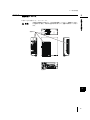
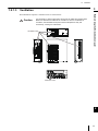
B.1
貼付場所
㹙ᮏయୖ㠃ࢺࢵࣉ࢝ࣂ࣮ࢆእࡋࡓ≧ែ㹛
⫼㠃ഃ
㆙࿌ࣛ࣋ࣝ
๓㠃ഃ
㹙ᮏయᗏ㠃㹛
〇㐀㖭ᯈ
๓㠃ഃ
ࣛࢭࣥࢫࣛ࣋ࣝ㸦㸧
⫼㠃ഃ
*1㸸OS࢜ࣉࢩࣙࣥᦚ㍕ࡢࡳ
40
PFU Limited Proprietary & Confidential
付録 B
B.2
装置ラベルについて
1
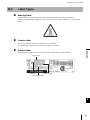
ラベルの種類
警告ラベル
本製品には、以下のような高温注意ラベルが貼ってあります。
電源を切った直後は本体内部が高温になっており、やけどのおそれがあります。
2
ライセンスラベル
Microsoft 社の COA(Certificate of Authenticity)ラベルです。
OS オプション搭載時のみ貼ってあります。
3
製造銘板
型名や製造番号が、以下のように記載されています。
ᆺྡ
付録
4
5
ᆺ␒ 〇㐀ᖺ᭶
〇㐀␒ྕ
6
J
PFU Limited Proprietary & Confidential
41
付録 C
カリフォルニア州法「過塩素酸塩の取り扱いに関する規制」について
付録 C カリフォルニア州法「過塩素酸塩の取
り扱いに関する規制」について
カリフォルニア州で「過塩素酸塩の取り扱いに関する規制」が制定されています。
C.1
規制対象
本製品の時計バックアップ用のリチウム一次電池は、過塩素酸塩含有量が 6ppb 以上であり、
規制の対象です。
C.2
適用範囲
カリフォルニア州で過塩素酸塩物質を管理(製造、輸送、使用など)するすべての取扱者に
適用されます。
C.3
過塩素酸塩物質の管理実践要求事項の表示
カリフォルニア州で過塩素酸塩物質を製造、流通、販売、使用、廃棄される場合、およびカ
リフォルニア州に輸出される場合は、個装箱、輸送箱(出荷梱包用)などに下記表示が義務
化されています。
Perchlorate Material - special handling may apply.
See www.dtsc.ca.gov/hazardouswaste/perchlorate
C.4
必要な対応
お客様において本製品、または本製品を組み込んだお客様製品をカリフォルニア州へ輸出さ
れる場合は、この州法への対応を実施してください。
42
PFU Limited Proprietary & Confidential
付録 D
他社製周辺機器をご利用の際の注意事項
付録 D 他社製周辺機器をご利用の際の注意事
項
他社製の周辺機器をご利用になる場合は、以下の点を確認してください。
• 本製品が、ご利用になる周辺機器のハードウェア条件を満たしていること
1
2
• ご利用の OS が、周辺機器の対応 OS に含まれていること
• ご利用の周辺機器がデバイスドライバを必要とする場合、そのドライバが最新版である
こと
• ご利用の周辺機器が、パワーマネジメント機能(省電力モード)をサポートしているこ
と
3
パワーマネジメント機能をサポートしていない周辺機器を接続した状態で、省電力モー
ドに移行すると、問題が発生する場合があります。
• その他、周辺機器の使用条件を満たしていること
4
付録
単独では正常動作する周辺機器であっても、他の周辺機器との組み合わせによって、不
具合が発生する可能性があります。
5
6
J
PFU Limited Proprietary & Confidential
43
付録 E
海外で使用する場合の注意事項
付録 E 海外で使用する場合の注意事項
本製品は、以下の国々に輸出できます。
本製品を最終製品の中に組み込んで使用する場合には担当営業までご相談くださ
い。
• 米国(UL60950-1、NRTL/C 取得(*1)、FCC Class A)
• カナダ(CSA60950-1、NRTL/C 取得(*1)
、ICES-003 Class A)
*1 認証機関 CSA にて規格取得
上記以外の国へ輸出をお考えの場合には、担当営業までご連絡ください。
44
PFU Limited Proprietary & Confidential
1
Preface
Thank you for purchasing our Embedded Computer AR2100 model 100J (hereafter referred to as
"Embedded Computer").
This is a small size Embedded Computer, and this document describes how to operate it.
Please review the information outlined in this manual before using the Embedded Computer.
2
August 2014
3
4
5
6
Intel and Intel Atom are registered trademarks of Intel Corporation in the U.S. and/or other countries.
VGA and PS/2 are registered trademarks of International Business Machines Corporation.
PCI Express is a registered trademark of PCI-SIG.
Microsoft is either a registered trademark or trademark of Microsoft Corporation in the United States
and/or other countries.
Other company names and product names are registered trademarks or trademarks of their respective
owners.
E
© 1999-2014 Intel Corporation
© PFU LIMITED 2014
PFU Limited Proprietary & Confidential
i
Important Notes
This manual contains important information that needs to be observed for the safe and correct operation
of the Embedded Computer.
Please read and thoroughly understand the contents of this manual before using this product.
Symbols
For your safety and that of others, follow the guidelines provided on the following pages concerning the
use of the Embedded Computer. Symbols are used throughout this manual. These are provided to
emphasize important points for your safety and that of others. The following are the symbols and their
meanings:
Warning
Ignoring the instructions under this symbol when using the Embedded Computer
may be hazardous or even lethal as well as damage to the Embedded Computer
and/or peripherals.
Caution
Ignoring the instructions under this symbol when using the Embedded Computer
may lead to injuries as well as damage to the Embedded Computer and/or
peripherals.
Safety Precautions
Warning
Be sure to obey the following warnings. Failure to observe these warnings may be
hazardous or even lethal as well as damage to the Embedded Computer and/or
peripherals.
Category
Electric shock and
fire
Warning
Do not dismantle or modify the Embedded Computer in any other way than
described in this manual. Doing so may cause fire, electric shock or a malfunction.
If the Embedded Computer is dismantled or modified, PFU LIMITED may not be
able to meet the request for repair of the Embedded Computer. When a component needs replacing, contact your sales representative.
Do not place anything on top of the Embedded Computer. Doing so may cause fire,
electric shock or a malfunction.
Do not place the Embedded Computer in direct sunlight, near a heater, or in a
humid or dusty environment. Doing so may cause fire or electric shock.
Do not obstruct the ventilation slots. This could cause overheating and fire.
In the event the Embedded Computer overheats, starts to smoke or smells
strange, turn the Embedded Computer power off, and unplug the DC power cable.
Contact the company where you purchased the Embedded Computer immediately.
Using the Embedded Computer in its current condition may cause fire or electric
shock. If this happens, data being transmitted may not be saved.
Do not damage or modify the cables. Do not twist the cables together, place
anything on them or place them where someone may trip over them. Do not use
the cables if they are damaged. Doing so may cause fire or electric shock.
ii
PFU Limited Proprietary & Confidential
Category
Electric shock and
fire
Warning
Do not touch the power plug with wet hands. Doing so may cause electric shock.
1
Do not touch the switch or power plug with wet hands. Doing so may cause electric
shock.
Do not cover the Embedded Computer while it is operating. Doing so may cause
overheating and fire, or a malfunction.
Do not touch any connecting cables during thunderstorms, doing so may cause
electric shock.
2
Be careful not to drop any foreign objects or other objects/things (such as
flammable products, liquids, or metallic objects) onto the Embedded Computer.
Also, do not place anything on the Embedded Computer to prevent things from
falling inside. Failure to do so may cause fire or electric shock.
Do not insert anything, such as screwdrivers or pens, into any openings or
connectors on the Embedded Computer. Doing so may cause an electric shock.
Do not replace the battery yourself, as there is a risk of explosion if the wrong type
is used. When the battery needs replacing, contact your sales representative. Our
service department will replace the battery.
3
Never use any flammable type cleaning sprays or any type of cleaning chemicals.
Doing so may cause fire or malfunction.
Do not touch the inside of the Embedded Computer while the Embedded Computer
is being charged. Doing so may cause burns or an electric shock.
Do not remove screws unless otherwise stated. Doing so may cause burns or an
electric shock.
4
Do not charge the Embedded Computer with a power-supply voltage that is over or
below the range listed in the Embedded Computer specification. Doing so may
cause electric shock, fire, or malfunction.
The Embedded Computer installation and the power supply work involved must be
performed by Service Personnel. Failure to do so may cause electric shock, fire, or
malfunction.
Damage and injury
Do not place the Embedded Computer on a slanted or unstable surface or in areas
subject to severe vibration.
Failure to do so may cause the Embedded Computer to fall and result in malfunction or injury.
5
Do not dispose of the Embedded Computer together with other garbage. If the
Embedded Computer is thrown into fire, it may explode.
Caution
Ignoring the instructions under this symbol when using the Embedded Computer
may lead to injuries as well as damage to the Embedded Computer and/or
peripherals.
Category
Caution
Cause of trouble
with the Embedded
Computer
Do not place the Embedded Computer on a slanted or unstable surface or in areas
subject to severe vibration.
Doing so may cause the Embedded Computer to malfunction.
6
Do not place anything on top of the Embedded Computer nor work on things on top
of the Embedded Computer. Doing so may damage the Embedded Computer or
may cause injury.
E
Do not drop the Embedded Computer. Doing so may cause the Embedded
Computer to malfunction.
Do not stack the Embedded Computer on another device, or install it except as
allowed in this manual. Doing so may cause the Embedded Computer to
malfunction.
PFU Limited Proprietary & Confidential
iii
Category
Caution
Cause of trouble
with the Embedded
Computer
Install this product indoors. Using the Embedded Computer outdoors may cause it
to malfunction.
Do not place the Embedded Computer in a location that is extremely hot or cold or
where the temperature changes drastically. Doing so may cause the Embedded
Computer to malfunction.
Do not use the Embedded Computer in an environment that is exposed to high
levels of salt. Doing so may cause the Embedded Computer to malfunction.
Do not place the Embedded Computer in areas that are subject to high levels of
shock or vibration. Doing so may cause the Embedded Computer to malfunction.
Do not place the Embedded Computer in a location where chemicals are present in
the air or where it comes in contact with chemicals. Doing so may cause the
Embedded Computer to malfunction.
Do not place the Embedded Computer in areas where strong magnetic fields are
generated, such as near a microwave oven. Doing so may cause the Embedded
Computer to malfunction.
Before moving the Embedded Computer, turn it off, then unplug and disconnect the
DC power cable from it. Moving the Embedded Computer with the cable still
connected may cause the Embedded Computer to malfunction.
Do not press the power switch strongly with an object such as a stick. Doing so
may cause the Embedded Computer to malfunction or fail.
Radiowave
interference
Do not place the Embedded Computer near devices that emit strong static
emissions such as radios or televisions. Doing so may cause the Embedded
Computer to malfunction or fail.
Make sure that the display, USB, and serial cables are all shielded.
Electrical shock
When performing maintenance, make sure to unplug and disconnect the DC power
cable from the Embedded Computer. Failure to do so may result in electric shock.
Operating Cautions
• It is the customer's responsibility to use this product and the manual provided with it.
• PFU LIMITED assumes no responsibility for any damage or loss of data that occurs as a result of
using this product. Also, restitution for damages due to malfunctioning of the Embedded Computer
shall not exceed the total cost of the Embedded Computer, regardless of the range of the damages
covered by the warranty.
• With the exception of the Embedded Computer itself, any special options and operating system
software that may be included with this product, PFU LIMITED bears no responsibility for
problems arising from hardware or software produced by other manufacturers.
• Modifying or dismantling the Embedded Computer is strictly prohibited.
• The Embedded Computer is not suited to advanced time control applications.
iv
PFU Limited Proprietary & Confidential
1
Battery Replacement
The Embedded Computer has a battery on board to retain setup information.
The battery needs to be replaced if one of the following conditions applies:
• The message "CMOS Battery Failure" is displayed in the Event Log.
• The settings cannot be saved correctly.
Contact your sales representative to replace the battery. Our service department will replace the battery.
2
Electromagnetic Compatibility (EMC)
EU
Embedded Computers are Class A equipment and suitable for installation in an industrial as well as
other commercial environments. Embedded Computers are designed to provide reasonable protection
against harmful interference if installed correctly as instructed in this manual.
USA - Federal Communications Commission (FCC)
FCC WARNINGS:
Changes or modifications not expressly approved by the party responsible for compliance could void the
user's authority to operate the equipment.
This equipment has been tested and found to comply with the limits for a Class A digital device,
pursuant to Part 15 of the FCC Rules. These limits are designed to provide reasonable protection against
harmful interference when the equipment is operated in a commercial environment. This equipment
generates uses, and can radiate radio frequency energy. If not installed and used in accordance with the
instruction manual, may cause harmful interference to radio communications. Operation of this
equipment in a residential area is likely to cause harmful interference in which case the user will be
required to correct the interference at his own expense.
Canada - Department of Communications (DOC)
3
4
5
6
This digital apparatus does not exceed the Class A limits for radio noise emissions from digital
apparatus set out in the Radio Interference.
Cet appareil numerique de la classe A est comforme a la norme NMB-003 du Canada.
Caution when Using a Display
It is recommended that the display is connected to the Embedded Computer with a display cable that is
equipped with a ferrite core.
PFU Limited Proprietary & Confidential
E
v
High Safety
This product has been designed and manufactured on the assumption that it will be used in office,
personal, domestic, regular industrial, and general-purpose applications. It has not been designed and
manufactured for use in applications (simply called "high-safety applications" from here on) that
directly involve danger to life and health when a high degree of safety is required, for example, in the
control nuclear reactions at nuclear power facilities, automatic flight control of aircraft, air traffic
control, operation control in mass-transport systems, medical equipment for sustaining life, and missile
firing control in weapons systems, and when provisionally the safety in question is not ensured. The user
should use this product with adopting measures for ensuring safety in such high safety applications. PFU
LIMITED assumes no liability whatsoever for damages arising from use of this product by the user in
high-safety applications, and for any claims or compensation for damages by the user or a third party.
Component Lifetimes and Consumable Supplies
• Some components of the Embedded Computer have a limited life expectancy. These components
become worn or deteriorate with time, thus affecting device operation.
It is recommended that these components be replaced within the recommended period of time.
• The recommended replacement period varies according to environmental conditions and the
frequency of operation. Using the Embedded Computer for 8 hours per day results in a component
lifetime of approximately 5 years. Note that component lifetimes are statistical measures that
provide no guarantee against the possibility of early Embedded Computer failure.
Longterm continuous operation and high ambient temperatures will both shorten the component
lifetime.
• The following major components have limited lifetimes:
hard disk drives, Solid State Drives (SSDs), CFast, fans, and batteries.
Cleaning the Embedded Computer
When the Embedded Computer is cleaned with a damp cloth using water or a diluted mild detergent,
make sure to tightly squeeze the cloth before wiping the Embedded Computer. When wiping the
Embedded Computer, make sure no water gets inside the Embedded Computer.
Power Consumption
• The amount of power consumed while the power switch is “off”: 1.3W or less
Unplugging the DC power cable can avoid power consumption while the DC power is switched off.
• The amount of power consumed while the Embedded Computer is operating is approximately 77W
for the PD-AR21AAAAE and approximately 64W for the PD-AR21ACAAE.
vi
PFU Limited Proprietary & Confidential
1
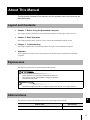
About This Manual
The layout and contents of this manual, and the symbols used in this manual, are
described below.
2
Layout and Contents
• Chapter 1 Before Using the Embedded Computer
This chapter explains the features of the Embedded Computer and the steps required to use it.
3
• Chapter 2 Basic Operation
This chapter describes basic operation such as turning the Embedded Computer on/off.
• Chapter 3 Troubleshooting
This chapter explains how to deal with problems during use of the Embedded Computer.
4
• Appendix
These appendices describe various specifications and cautions that are related to the Embedded
Computer.
Expressions
5
The following expressions are used throughout this manual:
Draws attention to a precaution that should be observed.
Also used to warn of unacceptable or dangerous practices.
Should always be read!
6
Refer
References related information in a different area of this manual, or in another manual.
Abbreviations
E
The following expressions and abbreviations are used throughout this manual:
Product name
Embedded Computer AR2100 model 100J
Abbreviations
Embedded Computer
PFU Limited Proprietary & Confidential
vii
This page is intentionally left blank.
viii
PFU Limited Proprietary & Confidential
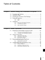
Table of Contents
1
Chapter 1 Before Using the Embedded Computer ..... 1
1.1
1.2
1.3
1.4
Functions and Features ........................................................
Installation Steps...................................................................
Checking the Contents of the Package.................................
Parts and Functions ..............................................................
1.4.1
1.4.2
1.5
2
3
4
5
Front..................................................................................... 5
Side ...................................................................................... 6
2
3
Installation ............................................................................. 7
1.5.1
1.5.2
1.5.3
Placing the Embedded Computer ........................................ 7
Connecting the Cables....................................................... 13
When Using DC Power ...................................................... 17
4
Chapter 2 Basic Operation ....................................... 19
2.1
Switching the Embedded Computer On/Off ........................ 20
2.1.1
2.1.2
2.2
Using a CFast Card............................................................. 23
2.2.1
2.2.2
2.2.3
2.3
Inserting a CFast Card ....................................................... 23
Removing a CFast Card .................................................... 25
Boot Device Settings.......................................................... 26
Removing/Attaching the Top Cover .................................... 27
2.3.1
2.3.2
2.4
Turning on the Embedded Computer................................. 21
Turning off the Embedded Computer................................. 22
Removing the Top Cover ................................................... 27
Attaching the Top Cover .................................................... 28
Installing/Removing an Expansion Card ............................. 29
2.4.1
2.4.2
2.4.3
Before Installation .............................................................. 29
Installing an Expansion Card ............................................. 30
Removing an Expansion Card ........................................... 32
E
PFU Limited Proprietary & Confidential
ix
Chapter 3 Troubleshooting ...................................... 33
3.1
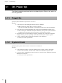
On Power Up ...................................................................... 34
3.1.1
3.1.2
3.2
Power On ........................................................................... 34
System Crash .................................................................... 34
Before You Call................................................................... 35
Appendix ...................................................................... 37
Appendix A Specifications .......................................................... 38
A.1
Embedded Computer Specifications.................................. 38
Appendix B Product Labels ........................................................ 40
B.1
B.2
Label Locations .................................................................. 40
Label Types ....................................................................... 41
Appendix C About "Perchlorate Best Management Practices" of
California Law ......................................................... 42
C.1
C.2
C.3
C.4
Regulation Compliance ......................................................
Scope .................................................................................
Labeling Best Management Practice Requirements for
Perchlorate Materials .........................................................
Required Correspondence .................................................
42
42
42
42
Appendix D When Using Third-Party Peripherals....................... 43
Appendix E Export Cautions ...................................................... 44
x
PFU Limited Proprietary & Confidential
Chapter 1
Before Using the
Embedded Computer
This chapter provides important information to
understand before using the Embedded Computer.
1.1
Functions and Features .............................................................. 2
1.2
Installation Steps ......................................................................... 3
1.3
Checking the Contents of the Package ...................................... 4
1.4
Parts and Functions .................................................................... 5
1.5
Installation ................................................................................... 7
Chapter 1
1.1
Before Using the Embedded Computer
Functions and Features
The Embedded Computer AR2100 model 100J is a compact embedded computer
that is suitable for various industrial applications. It features:
• An Intel® Atom™ processor is installed
• Up to 8GB of memory can be mounted
• 2.5-inch hard disk drive ×1 or SSD ×1 may be installed (optional)
• The following front-mounted connectors are provided:
• USB2.0 connectors ×4
• LAN connectors (10BASE-T/100BASE-TX/1000BASE-T) ×2
• Serial connectors (RS-232C) ×2
• VGA connector ×1
• DVI-D connector ×1
• PS/2 keyboard connector ×1 and mouse connector ×1
• Audio connectors (LINE IN ×1 and LINE OUT ×1)
• The following slot is mounted on the side of the Embedded Computer:
• CFast card slot (serial ATA) ×1
2
PFU Limited Proprietary & Confidential
1.2
1.2
Installation Steps
1
Installation Steps
Check the contents of the package
"1.3 Checking the Contents of the Package"
Confirm location for installation, then install the Embedded Computer
"1.5.1 Placing the Embedded Computer"
Attach the peripherals
"1.5.2 Connecting the Cables"
Confirm the installation of the peripherals
Connect the DC power cable
Before Using the Embedded Computer
Perform the steps below to install the Embedded Computer.
2
3
"1.5.2 Connecting the Cables"
Turn on the power
"2.1 Switching the Embedded Computer On/Off"
4
Install the OS (*1)
Start operations
5
*1: If the PFU OS option is selected, this operation is not needed.
6
E
PFU Limited Proprietary & Confidential
3
Chapter 1
1.3
Before Using the Embedded Computer
Checking the Contents of the Package
Check that all of the following items are included in the package. If any items are
missing, please contact your sales representative.
Embedded
Computer
Cable clamp (2)
Item
Embedded Computer
4
User Manual (this manual)
E.U.L.A. (optional)
Explanation
The actual Embedded Computer.
User Manual (this manual)
Operating manual for this product.
Cable clamp
Clamps for fixing the cables.
E.U.L.A. (optional)
E.U.L.A. for the preinstalled OS.
PFU Limited Proprietary & Confidential
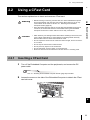
1.4
1.4
Parts and Functions
1
Parts and Functions
1.4.1
Before Using the Embedded Computer
This section explains the names and functions of the parts.
2
Front
2
1
3
4 5
6
7
3
9 10
11
12
13
14 1516 17
4
8
1
DC power input terminal
7
2
Serial connector
Two serial connectors that comply with the
RS-232C standard. They support transfer
speed of up to 115.2kbps.
3
4
LAN connector
Two LAN connectors for 10BASE-T/
100BASE-TX/1000BASE-T Ethernet
connections. Supports the Preboot eXecution Environment (PXE) function and the
Wake On LAN function.
5
6
8
Cable clamp hole
9
Keyboard connector
A connector for a keyboard that has a PS/2
6-pin Mini-DIN interface.
6
10 Mouse connector
A connector for a mouse that has a PS/2
6-pin Mini-DIN interface.
LAN Speed LED
11 VGA connector
LAN connectors 1 and 2 each have a
Speed LED, which indicates the speed of
the LAN connection. Lights orange when
operating at 1000Mbps, and lights green
when operating at 100Mbps.
12 DVI-D connector
LAN Link/Active LED
13 USB connector
LAN connectors 1 and 2 each have a Link
LED, which indicates the state of the LAN
connection. Lights up when the LAN
connection is established, and blinks when
data is being transferred.
5
This hole is used to attach the cable clamp
provided with the Embedded Computer.
The Embedded Computer has two cable
clamp holes.
PCI Express ×1 slot
This is used to install a PCI Express card.
Power switch
This switch turns the Embedded Computer
on and off. Hold the switch down for five
seconds plus to turn the power off.
An input terminal for a DC power cable
connection. DC 24V is supported.
A VGA connector to attach a VGA cable for
the display.
A DVI-D connector to attach a DVI cable for
the display.
E
Four Universal Serial Bus (USB) 2.0
connectors.
14 LINE OUT connector
A connector for a Line OUT audio cable.
PFU Limited Proprietary & Confidential
5
Chapter 1
Before Using the Embedded Computer
15 LINE IN connector
17 Power LED
A connector for a Line IN audio cable.
Lights green while the Embedded
Computer is turned on.
16 Hard disk access LED
Hard disk access: Lights green when data
is being written to or read from the hard
disk.
1.4.2
Side
1
1
CFast card slot
Slot for a CFast card.
6
PFU Limited Proprietary & Confidential
1.5
1.5
Installation
1
Installation
Warning
The Embedded Computer installation and the power supply work involved
must be performed by Service Personnel. Failure to do so may cause electric
shock, fire, or malfunction.
1.5.1
Placing the Embedded Computer
1.5.1.1
Detailed Dimensions
Before Using the Embedded Computer
This section details the installation requirements and installation procedures of the
Embedded Computer.
2
3
The following figures detail the various dimensions of the Embedded Computer.
4
Front
195mm
5
74mm
6
Rear
195mm
74mm
E
PFU Limited Proprietary & Confidential
7
Chapter 1
Before Using the Embedded Computer
Top
195mm
Rear
220mm
Front
Bottom
12.5mm
170mm
12.5mm
Four
M3 screw holes (*1)
28mm
Rear
170mm
Front
22mm
*1 4mm maximum insertion depth
Caution
8
Screws must never be inserted over 4mm deep. Failure to do so may result in
play in the Embedded Computer mounting.
PFU Limited Proprietary & Confidential
1.5
Installation
Left
1
Rear
Front
18mm
38mm
2
18mm
16mm
180mm
24mm
*1 4mm maximum insertion depth
Caution
Before Using the Embedded Computer
Four
M3 screw holes (*1)
Screws must never be inserted over 4mm deep. Failure to do so may result in
play in the Embedded Computer mounting.
3
Right
Front
Rear
Four
M3 screw holes (*1)
18mm
4
38mm
18mm
5
24mm
180mm
16mm
*1 4mm maximum insertion depth
Caution
Screws must never be inserted over 4mm deep. Failure to do so may result in
play in the Embedded Computer mounting.
6
E
PFU Limited Proprietary & Confidential
9
Chapter 1
Before Using the Embedded Computer
1.5.1.2
Installation Location
Adequate space for ventilation must always be kept as shown below:
• When installing the Embedded Computer horizontally
100mm or more
100mm or more
50mm or more
50mm or more
100mm or more
• When installing the Embedded Computer vertically (right side down)
100mm or more
100mm or more
100mm or more
50mm or more
20mm or more (*1)
*1 Keep an open space of 20mm or more below the ventilation slots.
10
Warning
Do not install the Embedded Computer in a way other than described above.
Contact your sales representative if the Embedded Computer needs to be
installed in a way other than described above.
Caution
Do not install the Embedded Computer in a completely enclosed space. Longterm operation in an enclosed space may cause malfunctions or other problems due a rise in temperature.
PFU Limited Proprietary & Confidential
1.5
1.5.1.3
Installation
1
Ventilation
Caution
It is necessary to leave ample space around the air intake and exhaust slots.
Make sure that there is sufficient air circulation. If there is insufficient air
circulation, the Embedded Computer's internal temperature may rise
excessively, causing it to malfunction.
Ventilation slots
Before Using the Embedded Computer
The Embedded Computer's ventilation slots are shown below:
2
3
4
5
Ventilation slots
6
E
PFU Limited Proprietary & Confidential
11
Chapter 1
Before Using the Embedded Computer
1.5.1.4
Operational Environment
The Embedded Computer requires the following environmental conditions.
Make sure to observe the following conditions when using the Embedded Computer. Failure to do so
may cause the Embedded Computer to fail.
Item
Temperature
Humidity
Specification
When operating with HDD
5 – 40°C
When operating without HDD
0 – 50°C
In power-off mode (Storage)
-20 – 60°C
When operating
5 – 90%RH
In power-off mode (Storage)
5 – 95%RH
Thermal gradient
15°C/Hr or less (non-condensing)
Humidity gradient
30%/Day or less
Vibration
0.5G
Shock
10G
Resistance to vibration and shock is not guaranteed when USB devices are in direct contact with
each other. USB devices are best connected via a USB cable.
Refer
"1.5.2 Connecting the Cables" (page 13)
12
PFU Limited Proprietary & Confidential
1.5
Connecting the Cables
1.5.2.1
Connecting the Cables
1
Connect the cables for peripherals to the Embedded Computer.
Note the following when connecting cables to the Embedded Computer.
Serial cables, cables for the display, keyboard cable, and mouse cable must be connected before
powering on the Embedded Computer.
The Embedded Computer is equipped with a hole to attach the cable clamp. By using the cable clamp,
cables that have connectors without locking mechanisms, including audio cables and USB cables, can be
prevented from falling off. Use the cable clamp according to the cable connection status and the direction of cabling.
Powering on the Embedded Computer without connecting or turning on the display may cause the
Embedded Computer to malfunction.
Caution
•
•
•
•
When connecting peripherals, turn off the Embedded Computer and peripherals,
and then disconnect the DC power cable (refer to "2.1 Switching the Embedded
Computer On/Off" (page 20)). Failure to do so may cause electric shock.
Do not touch the switch or power plug with wet hands. Failure to do so may
cause electric shock.
Do not expose to water, damage, modify, tie, roll up, drop, knock, pull, twist
together, force, bend, heat, place heavy objects on, or pinch (with something
such as a door) the DC power cable. Failure to do so damages the DC power
cable, which may cause electric shock or fire.
Do not place metallic parts near the power plug of the DC power cable. Failure to
do so may cause electric shock, fire or damage.
Before Using the Embedded Computer
1.5.2
Installation
2
3
4
5
6
E
PFU Limited Proprietary & Confidential
13
Chapter 1
Before Using the Embedded Computer
Audio cable
LAN cable
Serial cable
Mouse cable
DC power cable
USB cable
Keyboard cable
14
PFU Limited Proprietary & Confidential
VGA cable
DVI cable
1.5
1.5.2.2
Installation
1
Securing the Cables
Caution
Even if the cable clamp is not used, do not insert anything else into the cable
clamp hole. Failure to do so may cause the Embedded Computer to malfunction.
Attaching the Cable Clamp
1 Push the tip of cable clamp through its base, to form a loop.
Before Using the Embedded Computer
By using the cable clamp, cables that have connectors without locking mechanisms, including USB
cables, can be prevented from falling off.
The following procedure shows how to secure the USB cables. When using the cable clamp to secure the
USB cables, avoid applying unnecessary stress on the connectors of the USB cables.
2
3
4
2 Lift the lock-tab in the direction of the arrow to unlock it, allowing the loop size to
be adjusted.
Lock-tab
5
6
If the loop is too small, the USB cable may not be able to pass through the loop.
E
PFU Limited Proprietary & Confidential
15
Chapter 1
Before Using the Embedded Computer
3 With the cable clamp loop pointing downwards, press the stud at the base of the
cable clamp into the cable clamp hole.
Cable clamp hole
Cable clamp
Attaching the cables
1
Pass the USB cable through the cable clamp loop, and attach the connector
to the Embedded Computer.
2
Tighten the cable clamp to secure the USB cable.
Pull the tip of cable clamp to decrease the size of the loop and hold the cable.
Pull
If the loop is too large, the USB cable may come loose.
16
PFU Limited Proprietary & Confidential
1.5
1.5.3
Installation
1
When Using DC Power
Warning
1.5.3.1
The Embedded Computer installation and the power supply work involved
must be performed by Service Personnel. Failure to do so may cause electric
shock, fire, or malfunction.
DC Power Specification
The DC power requirements are as follows:
Before Using the Embedded Computer
When using DC power, follow the following conditions.
2
3
• Voltage is 24V.
• DC power must be insulated from AC power.
• DC power must be correctly grounded.
• The DC power source must be rated for use with Information Technology (IT) equipment
(IEC60950-1), with a maximum electrical current of less than 8.0A, and is provided by an SELV
circuit that does not produce hazardous energy levels.
• DC power source must have an emergency power-off switch.
When the DC power does not have the emergency power-off switch, an electric current breaker with
a capacity of 10A or larger must be added.
4
5
6
E
PFU Limited Proprietary & Confidential
17
Chapter 1
Before Using the Embedded Computer
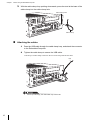
1.5.3.2
Connecting the DC Power Supply
This section describes how to construct a DC power cable to connect the DC power and the Embedded
Computer.
Usable DC power cables
Use DC power cables that satisfy the following conditions:
• Conductor size: AWG18
• Insulation: Rated to 80°C or higher, must be flameproof and flame-retardant.
• Compliant wire: UL1007 or CSA TR-64
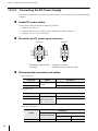
Pinout for the DC power input connector
DC 24V
DC 24V
4
3
3
4
2
1
1
2
GND
GND
Embedded Computer side
connector
Cable side connector
(viewed from the connection side)
Recommended connectors and cables
• Power connector
Connector
Housing
Crimp terminal
Vendor
MOLEX
Product ID
5557-04R
5556PBTL or 5556PBT
• DC power cable
Cable
DC24V cable
GND cable
Vendor
Product ID
Furukawa Electric,
UL1007, AWG18, Yellow
Hitachi Densen Shoji,
UL1007, AWG18, Black
SWCC Showa Holdings, or other vendors
• Terminal crimping tool
Product ID
Vendor
MOLEX
18
Hand crimping tool
57026-5000
PFU Limited Proprietary & Confidential
Automatic crimping machine
Crimping machine Modular crimp die
57275-4000
57022-3000
Chapter 2
Basic Operation
This chapter describes how to operate the
Embedded Computer.
2.1
Switching the Embedded Computer On/Off .............................. 20
2.2
Using a CFast Card .................................................................. 23
2.3
Removing/Attaching the Top Cover .......................................... 27
2.4
Installing/Removing an Expansion Card ................................... 29
Chapter 2
2.1
Basic Operation
Switching the Embedded Computer
On/Off
This section explains how to turn the Embedded Computer on/off.
Caution
•
•
•
•
Do not move or shake the Embedded Computer when it is turned on. Doing so
may cause electric shock, fire, damage to the Embedded Computer, or data to
be lost.
If condensation forms on the Embedded Computer, wait until the condensation
has evaporated before turning on the power. Not doing so may cause electric
shock or damage the Embedded Computer.
Follow the instructions below to turn the Embedded Computer on and off, not
doing so could cause data to be lost.
Do not press the power switch with an object such as a stick. Doing so may
cause the Embedded Computer to malfunction.
For emergency shutdowns of the Embedded Computer:
Warning
•
•
•
20
Familiarize yourself with the location of the emergency shutdown switch. If the
Embedded Computer overheats, starts to smoke or smell strange, immediately
shut the Embedded Computer power off.
If the DC power source has an emergency shutdown switch, use it to shut the
Embedded Computer power off.
If the DC power source does not have an emergency shutdown switch, unplug
the DC power cable or use a circuit breaker on the distribution board.
PFU Limited Proprietary & Confidential
2.1
2.1.1
Switching the Embedded Computer On/Off
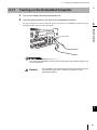
Turning on the Embedded Computer
1
1 Turn on the display and other peripherals first.
2 Press the power switch on the front of the Embedded Computer.
The power LED turns on green. When the power is turned on, the Embedded Computer first goes
through its POST (Power On Self Test) phase.
Power switch
Basic Operation
Power LED
lights up green
2
3
4
Do not shut the Embedded Computer's power off during the POST phase. Doing so may
cause a malfunction.
Caution
Do not press the power switch with an object such as a stick. Doing so
may break the power switch, resulting in a malfunction of the
Embedded Computer.
5
6
E
PFU Limited Proprietary & Confidential
21
Chapter 2
Basic Operation
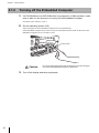
2.1.2
Turning off the Embedded Computer
1 If a CD-ROM drive or a DVD-ROM drive is connected to a USB connector, make
sure no disk is in the drive prior to turning off the Embedded Computer.
If a disk is still in the drive, eject it.
2 Exit the operating system (OS).
After exiting the OS, the Embedded Computer turns off automatically.
If the Embedded Computer does not turn off, press and hold the Power switch on the front of the
Embedded Computer for five seconds or more.
Power LED
turns off
Power switch
Caution
Do not press the power switch with an object such as a stick. Doing so
may cause the Embedded Computer to malfunction.
3 Turn off the display and other peripherals.
22
PFU Limited Proprietary & Confidential
2.2
2.2
Using a CFast Card
Using a CFast Card
1
This section explains how to insert and remove a CFast card.
Warning
•
Caution
•
•
•
•
•
•
2.2.1
2
Static electricity can damage CFast cards. Before handling a CFast card, first
touch a large metal object (or water tap/pipe) to discharge static electricity.
Note that direct skin-to-metal contact must be made.
Do not expose the CFast card to continuous direct sunlight, and do not store it
in a hot area.
Do not drop the CFast card on hard surfaces.
Do not put heavy objects on the CFast card.
Do not spill liquids, such as coffee, on the CFast card.
Be sure to store the CFast card back in its case when it is not being used.
3
Basic Operation
•
Before inserting or removing a CFast card, turn off the Embedded Computer
and the peripherals, and remove the DC power cable. Failure to do so may
cause electric shock. Refer to Section "2.1 Switching the Embedded
Computer On/Off" (page 20).
Since the CFast cards may still be hot right after the Embedded Computer is
turned off, the CFast cards must be removed after leaving the Embedded
Computer turned off for a while. Failure to do so may cause burns.
4
Inserting a CFast Card
1 Turn off the Embedded Computer and the peripherals, and remove the DC
power cable.
5
Refer
See "2.1 Switching the Embedded Computer On/Off" (page 20) for details.
2 Loosen the screw on the side of the Embedded Computer to detach the CFast
card slot cover.
6
CFast card slot cover
E
PFU Limited Proprietary & Confidential
23
Chapter 2
Basic Operation
3 Check the orientation of the CFast card and insert it into the CFast card slot.
After checking the orientation of the CFast card, inset it firmly all the way in.
4 Move the LOCK lever to the right to lock the CFast card.
LOCK lever
5 Re-attach the CFast card slot cover.
Attach the CFast card slot cover that was removed in Step 2 back to the way it was before.
The screw hole may break if the screw is over-torqued. The recommended tightening
torque is 0.49 N·m.
6 Re-connect the DC power cable, and turn on the Embedded Computer and
peripherals.
Do not use the Embedded Computer with the CFast card cover unattached. Using the
Embedded Computer without the CFast card slot cover attached may cause the
Embedded Computer to malfunction or fail.
24
PFU Limited Proprietary & Confidential
2.2
2.2.2
Using a CFast Card
1
Removing a CFast Card
1 Turn off the Embedded Computer and the peripherals, and remove the DC
power cable.
Refer
See "2.1 Switching the Embedded Computer On/Off" (page 20) for details.
card slot cover.
Basic Operation
2 Loosen the screw on the side of the Embedded Computer to detach the CFast
2
3
CFast card slot cover
3 Move the LOCK lever to the left to unlock the CFast card.
4
5
LOCK lever
4 Press the CFast card ejection button.
6
CFast card ejection button
E
PFU Limited Proprietary & Confidential
25
Chapter 2
Basic Operation
5 Pull out the CFast card from the CFast card slot.
6 Attach the CFast card slot cover removed in Step 2.
Do not use the Embedded Computer with the CFast card cover unattached. Using the
Embedded Computer without the CFast card slot cover attached may cause the
Embedded Computer to malfunction or fail.
2.2.3
Boot Device Settings
This section describes the Boot Device settings.
When a CFast card and a hard disk drive (or SSD) are both installed at the same time, the Embedded
Computer automatically boots from whichever device has the OS installed on it.
However, if both devices have an OS installed, the Embedded Computer needs to be told which it is to
boot off, by changing the settings to give the boot device with the preferred OS the appropriate priority.
To change the settings, access the Boot menu from the Setup program.
26
PFU Limited Proprietary & Confidential
2.3
2.3
Removing/Attaching the Top Cover
Removing/Attaching the Top Cover
1
This section explains how to remove and attach the top cover.
2.3.1
Removing the Top Cover
1 Turn off the Embedded Computer and the peripherals, and unplug all cables
from the Embedded Computer.
Basic Operation
This section explains how to remove the top cover on the Embedded Computer.
2
3
Refer
See "2.1 Switching the Embedded Computer On/Off" (page 20) for details.
2 Remove the screws (two screws) on the front of the Embedded Computer.
4
5
3 Remove the top cover.
Slide the top cover toward the front of the Embedded Computer.
6
Top cover
E
If the Embedded Computer is vertical, place it horizontally, as shown in the figure above,
before performing this step.
PFU Limited Proprietary & Confidential
27
Chapter 2
Basic Operation
2.3.2
Attaching the Top Cover
To attach the top cover, perform the top cover removal procedure in reverse.
Caution
Do not use the Embedded Computer with the top cover removed. Doing so
may cause fire.
The screw hole may break if the screw is over-torqued. The recommended tightening torque is
0.49 N·m.
28
PFU Limited Proprietary & Confidential
2.4
2.4
Installing/Removing an Expansion Card
Installing/Removing an Expansion
Card
This section explains how to install and remove an expansion card.
Before Installation
Caution
Before installing or removing an expansion card, turn off the Embedded
Computer and the peripherals, and leave the Embedded Computer turned off
for a while. Right after the Embedded Computer is turned off, the internal
components are still hot so there is a risk of getting burned.
2
Basic Operation
2.4.1
1
3
This section describes the installation location for the expansion card and specification of the expansion
card slot.
Expansion Card Slot
PCI Express ×1 slot
Specification
PCI Express x1 card can be mounted.
4
The power consumption of the expansion card that is installed in the Embedded Computer should
not exceed 25W.
5
Refer
See "Appendix D When Using Third-Party Peripherals" (page 43) when using any third-party
peripheral device.
6
E
PFU Limited Proprietary & Confidential
29
Chapter 2
Basic Operation
2.4.2
Installing an Expansion Card
This section explains how to install an expansion card.
When installing an expansion card, turn off the Embedded Computer and the
peripherals, and unplug all the connected cables from the inlet. Failure to do so
may cause electric shock ("2.1 Switching the Embedded Computer On/Off"
(page 20)).
Warning
Caution
•
•
•
The board and the soldered parts of an expansion card are exposed. These
parts may be damaged by static electricity. Before handling the cards, first
touch a metal part of the Embedded Computer to discharge static electricity.
Note that direct skin-to-metal contact must be made.
Do not touch the surface of the board or the soldered part. Make sure to hold
the metal clasps or the edge of the board.
The cards are vulnerable to static electricity, so put them on a conductive mat
first or keep them in the package until just before using them.
1 Turn off the Embedded Computer and the peripherals, and unplug all cables
from the Embedded Computer.
Refer
See "2.1 Switching the Embedded Computer On/Off" (page 20) for details.
2 Remove the top cover.
Refer
See "2.3.1 Removing the Top Cover" (page 27) for details.
3 Remove the fixing screw (one screw) on the slot cover of the slot where the
expansion card is installed.
Screw
30
PFU Limited Proprietary & Confidential
2.4
Installing/Removing an Expansion Card
4 Remove the slot cover.
1
Keep the removed slot cover in a safe location.
Slot cover
2
Basic Operation
3
5 Install an expansion card in the slot.
Insert it firmly into the slot. Install the expansion card as shown in the figure below, and fix it with
the screw that was removed in step 3.
Expansion card
4
Screw
5
The screw hole may break if the screw is over-torqued. The recommended tightening
torque is 0.49 N·m.
6
E
PFU Limited Proprietary & Confidential
31
Chapter 2
Basic Operation
6 Fix the expansion card into place.
Loosen the screws on the secure guards, and slide the guards to the edge of the expansion card.
Secure guard
Secure guard
The screw hole may break if the screw is over-torqued. The recommended tightening
torque is 0.49 N·m.
7 Attach the top cover that was removed in Step 2.
Refer
See "2.3 Removing/Attaching the Top Cover" (page 27) for details.
2.4.3
Removing an Expansion Card
To remove an expansion card, perform the expansion card installation procedure in reverse.
Caution
32
After removing the expansion card, make sure to attach the slot cover that was
removed. Also avoid using the Embedded Computer without reattaching the
slot cover first. Failure to do so may cause the Embedded Computer to
malfunction or fail.
PFU Limited Proprietary & Confidential
Chapter 3
Troubleshooting
Refer to this chapter if you encounter any problems
with the Embedded Computer.
If you cannot identify the cause of the problem or if
the symptoms persist, contact your sales
representative.
3.1
On Power Up ............................................................................ 34
3.2
Before You Call ......................................................................... 35
Chapter 3
Troubleshooting
3.1
On Power Up
The following explains problems that are considered typical. Refer to this section to
solve any problems.
3.1.1
Power On
[Symptom] The Embedded Computer does not turn on.
[Action]
• Is the DC power cable unplugged from the outlet or damaged?
Make sure the DC power cable is correctly connected.
The cable will need to be replaced if it is damaged (contact your sales representative).
• Power has been restored immediately after turning off the Embedded Computer power.
When restoring the Embedded Computer immediately after power-off, the Embedded
Computer may not be turned on. Wait at least 10 seconds before restoring.
• Depending on the connection display or display switching unit, turning on the display or
display switching unit after powering on the Embedded Computer may be required.
• Is there a problem with the Embedded Computer or other hardware?
Contact your sales representative.
3.1.2
System Crash
[Symptom] The system crashes while it is connected to a USB device.
[Action]
• Is the USB device broken, or does the USB device have a short circuit on the inside?
Remove the USB cable, and then check whether the Embedded Computer starts.
• Is a device that is undamaged recognized when it is connected to the Embedded Computer
that has been turned on?
Contact your sales representative.
34
PFU Limited Proprietary & Confidential
3.2
3.2
Before You Call
1
Before You Call
If you still cannot solve the problem, contact your sales representative.
Before calling the sales representative, have the following information ready:
2
• Model name and serial number
• Installed hardware options
• Changed factory settings in Setup program
• The OS
• Procedure prior to problem (what you were doing, error messages, etc.)
• Installation environment and connected devices
• The state of the LEDs
3
Troubleshooting
4
5
E
PFU Limited Proprietary & Confidential
35
Chapter 3
Troubleshooting
This page is intentionally left blank.
36
PFU Limited Proprietary & Confidential
Appendix
The appendix provides information about
specifications and optional components.
Appendix A
Specifications ........................................................................ 38
Appendix B
Product Labels ...................................................................... 40
Appendix C
About "Perchlorate Best Management Practices" of California
Law ........................................................................................ 42
Appendix D
When Using Third-Party Peripherals ..................................... 43
Appendix E
Export Cautions ..................................................................... 44
Appendix A
Specifications
Appendix A Specifications
This appendix provides technical specification details on the Embedded Computer.
A.1
Embedded Computer Specifications
The following are the specifications for the Embedded Computer.
Item
Specifications
Product name
Embedded Computer AR2100 model 100J
Model name
PD-AR21AAAAE(-**)
Power
DC power input: 24V ± 5%
CPU
Intel® Atom™ processor E3845
PD-AR21ACAAE(-**)
Intel® Atom™ processor E3825
Clock speed
1.91GHz
1.33GHz
Number of cores and
threads
4 cores/4 threads
2 cores/2 threads
Cache
L2-2MB
Chipset
Memory
(Indispensable option)
L2-1MB
—
DDR3L-1333 Unbuffered SO-DIMM
(ECC)
2GB/4GB/8GB (select one option)
DDR3L-1066 Unbuffered SO-DIMM
(ECC)
2GB/4GB/8GB (select one option)
Hard disk bay
(Selectable option)
2.5 inch ATA HDD × 1 or
2.5 inch ATA SSD × 1 available
2.5 inch ATA SSD × 1 available
CFast card
(Selectable option)
CFast card slot (serial ATA) × 1 available
Storage
Interfaces
Display
VGA × 1 and DVI-I × 1
LAN
1000BASE-T/100BASE-TX/10BASE-T × 2
(Preboot eXecution Environment (PXE) and Wake On LAN supported)
Serial
RS-232C × 2
Keyboard and mouse PS/2 × 2 (keyboard and mouse)
USB
USB 2.0 × 4
Audio
LINE IN × 1 and LINE OUT × 1
Expansion interface
PCI Express × 1
38
PCI Express 2.0 (5Gbps) 1 slot
Fan
Installed
Dimension (W × D × H)
195 × 220 × 74 (mm) (excluding rubber pads and protrusions)
Weight
2.5kg (approx.)
Power consumption
77W
Power Saving Mode (*1)
S4
PFU Limited Proprietary & Confidential
Not installed
64W
Appendix A
Specifications
*1 The power saving mode functions are as follows:
S0:
System powered is on and in operation.
S1:
CPU clock is stopped, but memory power is on and updated.
S2:
Same as S1, but CPU power is off.
S3:
Sleep mode. Power for almost all the components is off. However, memory continues to
operate.
S4:
Hibernate mode. The memory contents are swapped to the disk drive, and reloaded to
memory when the system is started again.
S5:
System power is off and only the necessary current for turning on the power is carried.
1
2
3
Appendix
4
5
6
E
PFU Limited Proprietary & Confidential
39
Appendix B
Product Labels
Appendix B Product Labels
This appendix explains the product label on the Embedded Computer.
Be careful the labels do not start peeling or become dirty.
B.1
Label Locations
[Top without the top cover]
Rear
Warning label
Front
[Bottom]
Product label
Front
License Label (*1)
Rear
*1: Only when the OS option is available.
40
PFU Limited Proprietary & Confidential
Appendix B
B.2
Product Labels
1
Label Types
Warning label
The Embedded Computer has the following warning label that warns of high temperatures.
Right after the Embedded Computer is turned off, the inside is still hot, and there is a risk of getting
burned.
2
3
License label
This is the Microsoft Certificate of Authenticity (COA) label.
The license label is attached only when the OS option is available.
4
Product label
This label provides information on the model name, serial number, and other details.
Model name
Appendix
5
Product ID
Serial number
Manufacture date
6
E
PFU Limited Proprietary & Confidential
41
Appendix C
About "Perchlorate Best Management Practices" of California Law
Appendix C About "Perchlorate Best
Management Practices" of
California Law
"Perchlorate Best Management Practices" is enacted in California.
C.1
Regulation Compliance
Lithium Primary Batteries used to backup the Embedded Computer clock are subject to regulation
because they contain more than 6ppb perchlorate.
C.2
Scope
The law applies to all operators who use (such as manufacturing, shipping, and using) perchlorate
material in California.
C.3
Labeling Best Management Practice
Requirements for Perchlorate Materials
When manufacturing, distributing, selling, using, disposing perchlorate materials, and when shipping
perchlorate materials to California, the exterior of all outer shipping packages and on consumer
packages shall be labeled or marked clearly with the following;
Perchlorate Material - special handling may apply.
See www.dtsc.ca.gov/hazardouswaste/perchlorate.
C.4
Required Correspondence
If you export Embedded Computers or a product that contains an Embedded Computer to California, be
sure to refer to this state law.
42
PFU Limited Proprietary & Confidential
Appendix D
When Using Third-Party Peripherals
Appendix D When Using Third-Party
Peripherals
Always check the following points when using any third-party peripheral device:
1
2
• Does the Embedded Computer meet the hardware requirements of the peripheral device?
• Are the peripherals compatible with the OS being used?
• When a peripheral device needs a device driver, does the Embedded Computer have the latest device
driver installed?
• Does the peripheral device support the Power Management functions (Power Saving mode)?
3
If these functions are not supported, problems may occur upon Power Saving mode.
• Are there any potential conflicts with other peripherals and their requirements?
Even if a particular peripheral device works fine in isolation, problems can still occur when it is used
in combination with other peripherals.
Appendix
4
5
6
E
PFU Limited Proprietary & Confidential
43
Appendix E
Export Cautions
Appendix E Export Cautions
Embedded Computers can be exported to the following countries.
Please consult with your sales representative when exporting a finished product that
contains an Embedded Computer.
• United States (UL60950-1, NRTL/C acquisition (*1), FCC Class A)
• Canada (CSA60950-1, NRTL/C acquisition (*1), ICES-003 Class A)
*1 Acquire the specifications from the Certification Authority CSA
To export Embedded Computers to countries other than the above, please consult with your sales
representative.
44
PFU Limited Proprietary & Confidential
組込みコンピュータ AR2100 モデル 100J
取扱説明書
Embedded Computer AR2100 model 100J
User Manual
P3XU-E881-01XA
発行日 2014 年 8 月
Date issued: August 2014
発行責任 株式会社 PFU
Issued by PFU LIMITED
Printed in Japan
•
•
•
•
•
•
•
•
本書の内容は、改善のため事前連絡なしに変更することがあります。
本書に記載されたデータの使用に起因する、第三者の特許権およびその他の権利の侵害については、弊社はその責を負いません。
無断転載を禁じます。
落丁、乱丁本は、お取り替えいたします。
The contents of this manual may be revised without prior notice.
PFU LIMITED assumes no liability for damages to third party copyrights or other rights arising from the use of any information in this
manual.
No part of this manual may be reproduced in any form without the prior written permission of PFU LIMITED.
Manuals with missing or wrongly collated pages will be replaced free of charge.