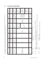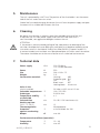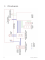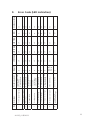
1
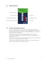
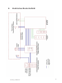
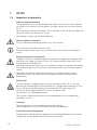
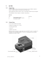
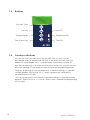
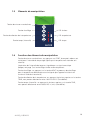
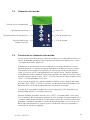
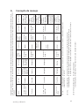
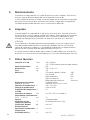
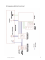
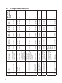
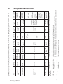
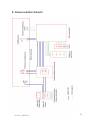
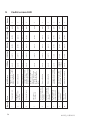
AL125
Bedienungsanleitung
DE
Instruction Manual
GB
Mode d‘emploi
FR
Manual de instrucciones
ES
Istruzioni per l’uso
IT
2
AL125_4 05/2013
Inhaltsverzeichnis
1.
AL125 . . . . . . . . . . . . . . . . . . . . . . . . . . . . . . . . . . . . . . . . . . . . . . . . . .
1.1Einleitung . . . . . . . . . . . . . . . . . . . . . . . . . . . . . . . . . . . . . . . . . . . . . . . . .
1.1.1 Bestimmungsgemäßer Gebrauch . . . . . . . . . . . . . . . . . . . . . . . . . . . . . . .
1.1.2 Verwendung von Symbolen . . . . . . . . . . . . . . . . . . . . . . . . . . . . . . . . . . .
1.2
Wichtige Hinweise . . . . . . . . . . . . . . . . . . . . . . . . . . . . . . . . . . . . . . . . . .
1.3Auspacken . . . . . . . . . . . . . . . . . . . . . . . . . . . . . . . . . . . . . . . . . . . . . . . .
1.4Anschließen . . . . . . . . . . . . . . . . . . . . . . . . . . . . . . . . . . . . . . . . . . . . . . .
1.5Bedienelemente . . . . . . . . . . . . . . . . . . . . . . . . . . . . . . . . . . . . . . . . . . . .
1.6
Funktion der Bedienelemente . . . . . . . . . . . . . . . . . . . . . . . . . . . . . . . . . .
4
4
4
4
5
6
6
7
7
2.
Bedienung . . . . . . . . . . . . . . . . . . . . . . . . . . . . . . . . . . . . . . . . . . . . . . . 8
3.
Beeper . . . . . . . . . . . . . . . . . . . . . . . . . . . . . . . . . . . . . . . . . . . . . . . . . . 8
4.
Bedienkonzept . . . . . . . . . . . . . . . . . . . . . . . . . . . . . . . . . . . . . . . . . . . 9
5.
Wartung . . . . . . . . . . . . . . . . . . . . . . . . . . . . . . . . . . . . . . . . . . . . . . . 10
6.
Reinigung . . . . . . . . . . . . . . . . . . . . . . . . . . . . . . . . . . . . . . . . . . . . . . 10
7.
Technische Daten . . . . . . . . . . . . . . . . . . . . . . . . . . . . . . . . . . . . . . . . 10
8.
Blockschaltbild . . . . . . . . . . . . . . . . . . . . . . . . . . . . . . . . . . . . . . . . . . 11
9.
LED-Fehlercode . . . . . . . . . . . . . . . . . . . . . . . . . . . . . . . . . . . . . . . . . . 12
AL125_4 05/2013
3
1.AL125
1.1Einleitung
Bedienungsanleitung lesen, ehe Sie das Gerät in Betrieb nehmen. Der Hersteller übernimmt keine Haftung bei nicht sachgemäßer Benutzung des Gerätes und
Nichteinhaltung der Bedienungsvorschriften.
1.1.1
Bestimmungsgemäßer Gebrauch
Der Thermoreaktor darf ausschließlich zum Erhitzen von verschlossenen 16-mm-Ø
Küvettenteströhrchen verwendet werden.
Grundsätzlich ist beim Starten des Heizvorgangs und während der Heizperiode die
Schutzhaube geschlossen zu halten.
Die zu wählende Temperatur und das entsprechende Zeitintervall sind Küvettentestabhängig und sind in der zu den Küvettentest gehörenden Analysenvorschrift angegeben. Auf die Einhaltung dieser Angaben ist unbedingt zu achten.
Die am Gerät angebrachten Schilder weisen auf die Gefahren hin, denen der
Benutzer beim Betrieb oder bei Wartungsarbeiten ausgesetzt ist. Die Etiketten dürfen
nicht entfernt werden und müssen, wenn sie unleserlich geworden sind, durch neue
ersetzt werden.
1.1.2
Verwendung von Symbolen
In dieser Anleitung wurden folgende Symbole verwendet, um auf eine mögliche
Personengefährdung, Sachschäden bzw. nützliche Informationen hinzuweisen:
ELEKTRISCHE GEFAHR!
Bezeichnet eine mögliche Gefährdung des Anwenders. Bei Nichtbeachtung können
Tod oder schwerste Verletzungen die Folge sein.
ACHTUNG!
Weist auf mögliche Sachschäden hin. Bei Nichtbeachtung können Geräte ernsthaft
beschädigt werden.
i
WICHTIG!
Bezeichnet Anwendungstipps und andere besonders nützliche Informationen.
ACHTUNG!
Heiße Oberfläche! Nicht berühren: Verbrennungsgefahr!
4
Bedienungsanleitung lesen, bevor Sie das Gerät in Betrieb nehmen.
AL125_4 05/2013
1.AL125
1.2
Wichtige Hinweise
Hinweise zum Aufstellungsort
Der Aufstellungsort darf weder extrem heiß oder kalt, noch feucht oder staubig sein.
Hitze und Kälte können die Funktionsfähigkeit des Thermoreaktors beeinträchtigen.
Feuchtigkeit und Staub können zu einem Ausfall des Thermoreaktors führen.
Stellen Sie den Thermoreaktor nicht in unmittelbarer Nähe von Wärmequellen wie
Heizkörpern oder Radiatoren auf. Das Gerät darf zudem keinen mechanischen Vibrationen oder Stößen ausgesetzt werden.
Die an der Unter- und Rückseite des Gerätes angebrachten Lüftungsschlitze dürfen
nicht abgedeckt sein.
Hinweise zum Netzanschluss
Verwenden Sie ausschließlich das für Ihr Land geeignete Netzkabel.
Die Netzsteckdose sollte sich in direkter Nähe befinden und leicht zugänglich sein.
Der Thermoreaktor kann nur durch Ziehen des Netzsteckers aus der Steckdose ganz
vom Netz getrennt werden.
Sicherheitshinweise zum Betrieb
Das Netzkabel darf nicht beschädigt werden. Stellen Sie keine Gegenstände auf das
Netzkabel, und sorgen Sie dafür, dass keine Knoten am Kabel auftreten. Um das
Kabel zu lösen, ziehen Sie stets am Stecker und nie am Kabel selbst. Ein beschädigtes
Netzkabel kann zu Brand oder Stromschlägen führen.
Achten Sie darauf, dass die Lüftungsschlitze nicht verdeckt werden. Die Luftzirkulation im Thermoreaktor ist erforderlich, um eine Überhitzung zu vermeiden. Wird Sie
beeinträchtigt können Brand oder ein Ausfall des Thermoreaktors die Folge sein.
Öffnen Sie den Thermoreaktor niemals eigenständig. Andernfalls besteht die Gefahr
eines Stromschlags oder anderer Personenschäden. Der Thermoreaktor darf nur von
Fachpersonal geöffnet und gewartet werden.
i
Sicherheitsvorschriften
Der Heizblock kann bei entsprechender Programmierung eine Temperatur von
150 °C erreichen und zwar sowohl während der Heizphase (wenn die HEAT-LED
leuchtet) als auch während der Abkühlphase.
Während dieser Zeit kann die Unterseite des Gerätes heiß sein!
Nicht berühren, Verbrennungsgefahr!
Die bei den Arbeiten verwendeten Materialien müssen bei den Temperaturen, die
vom Gerät erreicht werden, beständig sein.
Bitte unbedingt Klarsichtdeckel schließen, wenn Küvettentests im Gerät erhitzt werden.
Reinigung
Vor Beginn der Reinigungsarbeiten immer den Netzstecker ziehen. Die Heizplatte
muss bei Reinigungsarbeiten kalt sein. Die Reinigung erfolgt mit einem feuchten Tuch
und nicht brennbaren, nicht korrosiven Reinigungsmitteln.
Schutzvorrichtungen
Die Schutzvorrichtungen müssen gegen die vom Gerät erreichten Temperaturen und
die beim Arbeiten benutzten Materialien und Reagenzien beständig sein.
AL125_4 05/2013
5
1.AL125
1.3Auspacken
Heben Sie den Thermoreaktor vorsichtig aus der Verpackung und überprüfen Sie das
Zubehör auf Vollständigkeit.
Bewahren Sie den Originalkarton und das Verpackungsmaterial für den Fall auf, dass
Sie den Reaktor einschicken oder anderweitig transportieren müssen.
Stückliste
TeilAnzahl
1Thermoreaktor AL1251
2Netzkabel (Europa-Version)1
3Bedienungsanleitung1
1.4 Anschließen
Auf der Rückseite des Thermoreaktors befindet sich:
• Schiebeschalter für Netzspannung
• Stecker für Netzkabel
• Gerätesicherung 4 AT
• Netzschalter (0/I)
Das Gerät ist mit einem Wahlschalter für 115 V / 230 V ausgerüstet. Dieser
befindet sich an der Geräterückseite. Erst wenn die vorhandene Netzspannung am
Schiebeschalter richtig eingestellt ist und der Netzschalter in der Position „0“ ist,
darf das Gerät über das mit Schutzleiter versehene Kabel an das Netz angeschlossen
werden.
Schutzhaube
Gerätesicherung
Stecker für Netzkabel
6
Schiebeschalter
für Netzspannung
Netzschalter
AL125_4 05/2013
1.5Bedienelemente
Start-Taste / Timer
Aufheiz-Taste
Heat LED
Temperatur-Wahl-Taste
Temperatur LEDs
Zeit (Intervall)-Wahl-Taste
Zeit LEDs
AL125
1.6
Funktion der Bedienelemente
Start-Taste / Timer: Mit der “START“-Taste wird (nachdem die Solltemperatur
erreicht ist) die Zeitmessung (Countdown) für das eingestellte Zeitintervall aktiviert.
Der Ablauf des Zeitintervalls wird akustisch angekündigt (Beeper, s.S. 7) und die
Heizung automatisch abgeschaltet.
Aufheiz-Taste: Mit der „HEAT“-Taste wird (nachdem das Gerät mit dem
Hauptschalter I/O eingeschaltet wurde) der Aufheizvorgang für die eingestellte
Solltemperatur aktiviert.
Temperaturwahl-Taste: Durch mehrfaches Drücken der Taste „TEMP“ wird zwischen
100/120/150°C Solltemperatur gewählt (Scrollen).
Zeitwahl-Taste: Durch mehrfaches Drücken der Taste „TIME“ wird zwischen den
Zeitintervallen 30/60/120/∞ (min) gewählt (Scrollen).
AL125_4 05/2013
7
2.Bedienung
In diesem Kapitel wird die Bedienung Schritt für Schritt für eine Standardanwendung
beschrieben. Von der Standardanwendung abweichende Vorgehensweisen werden in
der Tabelle „Bedienkonzept“ (Seite 9) beschrieben.
Das Gerät wird mit dem Netzschalter an der Rückseite eingeschaltet (Position I). Nach
dem Einschalten zeigt das Gerät automatisch die zuletzt eingestellte Temperatur und
die zuletzt gewählte Zeitspanne an. Die entsprechenden LEDs auf der Frontplatte
leuchten. Nach dem Einschalten des Netzschalters heizt das Gerät noch nicht auf,
dazu muss die „HEAT“-Taste gedrückt werden. Nach dem Drücken der „HEAT“-Taste
blinkt die Heat-LED.
Vor und nach dem Drücken der „HEAT“-Taste können Temperatur- u. Zeiteinstellungen verändert werden. Während der Aufheizphase blinkt die Temperatur-LED,
die Zeit-LED leuchtet dauernd.
Wenn die eingestellte Solltemperatur erreicht ist, wechselt die blinkende TemperaturLED auf Dauerleuchten.
Der Timer beginnt mit der Zeitmessung entsprechend dem eingestellten Wert nach
Drücken der Taste „START“. Sobald die Zeitmessung beginnt, wechselt die Zeit-LED
von Dauerleuchten auf Blinken. Wenn die eingestellte Zeitspanne abgelaufen ist,
leuchten die Zeit-LED und die Temperatur-LED, während die Heat-LED aus ist (Heizung ist abgeschaltet).
3.Beeper
8
Temperatur oder Zeit weiterschalten:
kurzer Doppel-Beep
(zwei Frequenzen)
Heizung (per Heat-Taste) einschalten:
langer Beep (eine Frequenz)
Heizung (per Heat-Taste) vorzeitig abschalten:
langer Beep (eine Frequenz)
Temperatur-Sollwert ist erreicht:
achtfacher kurzer Beep
(zwei Frequenzen)
Starten des Timers (per Start-Taste):
langer Beep (eine Frequenz)
Timer ist abgelaufen:
sechzehnfacher kurzer Beep
(zwei Frequenzen)
Zur Zeit ungültige Taste gedrückt (z.B. Start-Taste wenn Aufheizen noch nicht beendet):
kurzer einfacher Beep
(eine Frequenz)
Fataler Fehler,
Gerät hat sich automatisch abgeschaltet:
LEDs zeigen Fehlercode
(siehe S. 12/13)
anhaltender Dauer-Beep
(zwei Frequenzen), bis Gerät über
Netzschalter ausgeschaltet wird.
AL125_4 05/2013
AL125_4 05/2013
An
An
3. Wartet auf
START Taste
4. Zeit läuft
Dauernd an
Dauernd an
Blinkt
Dauernd an
Dauernd an
An (zuletzt
gewählte
Zeit)
An (zuletzt
gewählter
Sollwert)
Blinkt
Time-LED
Temp.-LED
Drücken =>
Zustand 1
Drücken =>
Zustand 1
Ignorieren
Drücken =>
Zustand 1
Ignorieren
Wenn t=∞:
ignorieren
Wenn nicht
t=∞: Start
möglich
Ignorieren
Start-Taste
Drücken: =>
Zustand 2
Heat-Taste
Ignorieren
Einstellen
möglich
Einstellen
möglich
Einstellen
möglich
Temp-/TimeTaste
Zeit-LED
blinkt bedeutet:Timer läuft
an bedeutet: Timer läuft noch nicht oder nicht mehr
Temp.-LED blinkt bedeutet:Sollwert ist nicht erreicht, Aufheizen (bzw. Abkühlen) läuft
an bedeutet: in Verbindung mit der Heat-LED an: Sollwert ist erreicht und wird gehalten
in Verbindung mit der Heat-LED aus: zeigt nur Sollwert an, Istwert kann anders sein
aufheizen oder Temperatur halten (wenn Temperatur über Sollwert, abkühlen lassen)
nicht heizen
An
2. Aufheizen
an bedeutet:
aus bedeutet:
Aus
1. Wartet auf HEAT
Taste
Heat-LED
Heat-LED
Zustand
Temperatur
halten
Temperatur
halten
Wenn
Solltemperatur
erreicht:
Zustand 3
Aufheizen
oder
abkühlen
lassen
Wenn Zeit
abgelaufen:
Zustand 1
Wenn zu
sehr von
Solltemperatur
entfernt:
Zustand 2
Nach
Ändern von
Solltemperatur:
Zustand 2
Wenn Start
gedrückt:
Zustand 4
(t≠∞)
Wenn HEAT
Taste gedrückt:
Zustand 2
Nächster
Zustand
Aus
Heizung
Nach Einschalten mit dem Netzschalter an der Geräterückseite heizt das Gerät nicht; dazu muss die Taste HEAT gedrückt werden.(Zustand 1)
Nach der Aufheizphase startet die voreingestellte Zeitmessung erst nach Drücken der START Taste.(Zustand 3)
4.Bedienkonzept
9
5.Wartung
Der Reaktor ist mit einer 4-A-trägen Sicherung abgesichert. Diese befindet sich auf
der Rückseite unterhalb des Netzschalters.
Sollte die Sicherung gewechselt werden müssen, wird der Reaktor zuerst vom Netz
getrennt (Ziehen des Netzsteckers aus der Netzsteckdose) und dann der Sicherungshalter mit einem geeigneten Werkzeug aus der Arretierung gelöst.
6.Reinigung
Der Reaktor wird vom Netz getrennt (Ziehen des Netzsteckers aus der Netzsteckdose).
Reinigungsarbeiten erst vornehmen, wenn der Thermoreaktor vollständig abgekühlt
ist. Zur Reinigung eignet sich ein feuchtes Tuch mit nicht brennbaren, nicht aggressiven schleif- und scheuermittelfreien Detergenzien.
ACHTUNG:
Für den Fall, dass in dem Heizblock eine oder mehrere Küvetten platzen und/oder
Inhalte der Küvetten unbeabsichtigt ausgetreten sind, muss die sichere Entsorgung
des Küvettenglases und -inhalts gemäß den Angaben im entsprechenden Sicherheitsdatenblatt (Kapitel 6 und/oder 13) erfolgen.
Ein kontaminierter Reaktor darf nicht weiterverwendet werden und muss für den
Austausch des Aluminiumblocks zum Hersteller oder einem autorisierten
Servicecenter geschickt werden.
7.
Technische Daten
Netzanschluss
V/Hz
230 / 50-60 oder
115 / 50-60 (über Wahlschalter)
LeistungsaufnahmeW 550
Abmessungen
mm
248 x 219 x 171
Gewicht
kg3,9
Werkstoffe
Gehäuse Ober-/Unterteil: ABS
Innengehäuse:PBT
Schutzgitter: PPS
Klarsichtdeckel:PC
Heizblock:
Aluminium
Küvettenaufnahme
24 Bohrungen,
Aluminiumblock
Durchmesser 16,2 mm ± 0,2 mm
Temperaturwahl
°C
100 / 120 /150
Temp.-Überwachung
Pt100 A-Klasse
Temperaturstabilität
°C
±1
am Pt100
Zeitintervalle
min
30 / 60 / 120 / und unbegrenzt (∞)
Aufheizgeschwindigkeit
(20°C --> 150°C)
min
12
SteuerungMikroprozessor
Überhitzungsschutz
°C
am Thermoblock bei 190
Beeper (Piezo Summer) dB
max. 88
Umgebungsbed. Temp.
relative Feuchte
10
°C
%
10 – 40
max. 85
AL125_4 05/2013
8.
Elektrisches Blockschaltbild
AL125_4 05/2013
11
12
Fehler auf Platine
Ansprechen der
Schutzschaltung
ADC-Fehler
Kabelbruch
2
3
4
5
ein
ein
ein
ein
100° ein
120° aus
150° ein
Fehler auf Platine
Fehler auf Platine
Zuleitung zum Pt100
unterbrochen
Fehler auf Platine
EMV-relevante Störung von
außen (HF, Funken etc)
Gerät überhitzt
unterer Referenzwert
außerhalb Toleranz
oberer Referenzwert
außerhalb Toleranz
Temperaturmessung
am oberen Anschlag
Programmabsturz
Übertemperatur auf
Platine
6
7
8
9
10
ein
ein
ein
Pt100 nicht richtig auf
Alublock befestigt;
Kurzschluss des Pt100;
verringerte oder gar keine
Heizleistung
Timeout beim Aufheizen
ein
aus
aus
aus
aus
ein
aus
ein
Zuleitung zum Pt100
unterbrochen; sehr abrupte
Temperaturänderung
aus
aus
LED 30 min.
Fehler auf Platine
ein
ein
Netzfrequenz unter 50Hz
oder über 60Hz;
Fehler auf Platine
Netzfrequenz
1
Temp-LEDs
mögliche Ursachen
Fehler
Fehler-Nr
ein
aus
aus
ein
ein
ein
ein
aus
aus
aus
LED 60 min.
aus
ein
aus
ein
ein
aus
aus
ein
ein
aus
LED 120 min.
aus
aus
aus
ein
aus
ein
aus
ein
aus
ein
LED ∞
ja
nein
ja
ja
ja
ja
ja
ja
ja
ja
Piepton
Daueralarm
9.LED-Fehlercode
AL125_4 05/2013
AL125_4 05/2013
13
Content
1.
AL125 . . . . . . . . . . . . . . . . . . . . . . . . . . . . . . . . . . . . . . . . . . . . . . . . .
1.1Introduction . . . . . . . . . . . . . . . . . . . . . . . . . . . . . . . . . . . . . . . . . . . . . .
1.1.1Preface . . . . . . . . . . . . . . . . . . . . . . . . . . . . . . . . . . . . . . . . . . . . . . . . . .
1.1.2 Guide to symbols . . . . . . . . . . . . . . . . . . . . . . . . . . . . . . . . . . . . . . . . . .
1.2
Important information . . . . . . . . . . . . . . . . . . . . . . . . . . . . . . . . . . . . . .
1.3Unpacking . . . . . . . . . . . . . . . . . . . . . . . . . . . . . . . . . . . . . . . . . . . . . . .
1.4Connecting . . . . . . . . . . . . . . . . . . . . . . . . . . . . . . . . . . . . . . . . . . . . . .
1.5Buttons . . . . . . . . . . . . . . . . . . . . . . . . . . . . . . . . . . . . . . . . . . . . . . . . .
1.6
Function of buttons . . . . . . . . . . . . . . . . . . . . . . . . . . . . . . . . . . . . . . . .
14
15
15
15
15
16
16
16
18
18
2.
Work session . . . . . . . . . . . . . . . . . . . . . . . . . . . . . . . . . . . . . . . . . . . 19
3.
Beeper . . . . . . . . . . . . . . . . . . . . . . . . . . . . . . . . . . . . . . . . . . . . . . . . . 19
4.
Function schematics . . . . . . . . . . . . . . . . . . . . . . . . . . . . . . . . . . . . . . 20
5.
Maintenance . . . . . . . . . . . . . . . . . . . . . . . . . . . . . . . . . . . . . . . . . . . . 21
6.
Cleaning . . . . . . . . . . . . . . . . . . . . . . . . . . . . . . . . . . . . . . . . . . . . . . . 21
7.
Technical data . . . . . . . . . . . . . . . . . . . . . . . . . . . . . . . . . . . . . . . . . . . 21
8.
Wiring diagramm . . . . . . . . . . . . . . . . . . . . . . . . . . . . . . . . . . . . . . . . 22
9.
Error code (LED indication) . . . . . . . . . . . . . . . . . . . . . . . . . . . . . . . . 23
AL125_4 05/2013
1.AL125
1.1Introduction
Please read the manual before using the unit in particular taking note of the warning
symbols listed below.
The manufacture does not take responsibility for any issues caused by use of the unit
not in accordance with the instructions laid out in this manual.
1.1.1Preface
The reactor is only suitable for 16 mm Ø test tubes, closed with a lid.
The unit has a transparent cover, which has to be closed during the heating process.
The required temperatures and the corresponding time periods are specific for the
different test tube types and specified in the corresponding method descriptions.
Don’t exceed temperatures or time spans in any case.
All warning labels must NOT be removed and should be replaced if they become
damaged or faded.
1.1.2
Guide to symbols
The symbols below are used in this manual to indicate where there is risk of injury or
damaging devices or to indicate especially useful information:
DANGER!
Indicates risk of injury.
When not following instructions, severe injury or death may result.
ATTENTION!
Indicates possible damage to devices.
When not following instructions, devices may be heavily damaged.
IMPORTANT!
Indicates hints on operation and other useful information.
ATTENTION!
Hot surfaces! Do not touch, risk to be badly burned!
Read all instructions before using the instrument.
AL125_4 05/2013
15
1.AL125
1.2
Important information
Note on reactor placement
The setup location must not be extremely hot, cold, humid or dusty. Heat and cold
can impair the functionality of the reactor. Humidity and dust can cause the reactor
to fail.
Do not place the reactor near heaters such as radiators or the like. Do not expose the
reactor to mechanical vibrations or jarring.
Do not block or cover the ventilation openings.
Notes on power connection
Only use the power cord designated for use in your country.
i
The wall outlet should be within easy reach.
Pulling the power plug is the only way to disconnect the reactor from the power
source
Safety instructions for operation
The power cord must not be damaged. Do not place any objects on the power cord
and make sure it does not have any knots. To unplug the cord, always pull on the
plug and not on the cable itself.
Avoid covering the ventilation slots. Air circulation is necessary to prevent the reactor
from overheating. If the air circulation is restricted it could cause fire or damage the
reactor.
Never open the reactor housing yourself. There is a danger of electric shock
and other hazards. The reactor may only be opened and serviced by qualified
professionals.
Safety rules
The heating block if programmed, may reach a temperature of 150 °C, this happens during the heating phase when the red LED is lighted. Please note the unit will
remain hot during the cooling phase even though the LED-light may be off.
During this phase the base of the instrument may be very hot!
Do not touch, risk to be badly burned!
The materials used during the work must be compatible with the temperatures
reached by the unit.
Cleaning
16
The heating plate must be allowed to cool before cleaning.
Use a damp cloth with a non flammable, non corrosive detergent .
Personal Protection Equipment
The equipment used for personal protection must be compatible with the reached
temperature and the dangers due to the working materials.
AL125_4 05/2013
1.AL125
1.3Unpacking
Carefully inspect all items to ensure that every part on the list below is present
and no visible damage has occurred during transportation.
Store the packing material to return the unit for repair or other kinds of transport.
The table below shows the parts included in the packing.
Part list
PartQuantity
1Thermoreactor AL1251
2
Power cord (European version)
1
3Instruction manual1
1.4 Connecting
On the reverse side of the reactor:
• Selector for voltage 115 V / 230 V
• Plug for power cord
• Fuse 4 AT
• ON/OFF Switch (0/I)
Before connecting to power supply check that the ON/OFF switch is turned to “0”
and check that the voltage selector (115 V/230 V) corresponds to the voltage
supplied by the electric socket.
Cover
Fuse
Plug for power cord
AL125_4 05/2013
Selector
for voltage
ON/OFF Switch
17
1.5Buttons
Start key / Timer
Heat key
Heat LED
Temperature key
Temperature LEDs
Time (interval) key
Time LEDs
AL125
18
1.6
Function of buttons
Start key (for timer): By pressing this key the work cycle will start with the
pre-selected values for temperature and time. At the end of the work cycle the
beeper will sound (Beeper, see p. 7) and the heater automatically switches off.
Heat key: By pressing this key (after switching the instrument on using the main on/
off switch see page 17) the reactor will heat up to the pre-selected temperature.
Temp key: By pressing this key the temperature is selected (scrolling). It is possible
to select between 100/120 and 150 °C. When a temperature is selected the
corresponding LED will light.
Time key: By pressing this key the time is selected (scrolling). It is possible to select
between: 30/60/120 min or ∞ (infinite). When a time is selected the corresponding
LED will light.
AL125_4 05/2013
2.
Work session
This section describes the use of the reactor for a standard application.
For further applications please refer to “Function schematics” (page 20).
After the unit is switched on (main switch, reverse side, position I) the keypad
automatically shows the last selected temperature and time span.
The corresponding LEDs are lighted.
After switching on the block heating does not commence automatically.
For heating up the unit press the “Heat” key.
After pressing this key the Heat LED is lighted.
Before and after pressing the “Heat” key temperature and time span still can be
changed.
During heating up the Temperature LED will light intermediately, when the selected
temperature is reached the Temperature LED is lighted permanently.
By pressing the “Start” key the timer starts the work cycles corresponding to the chosen time span (indication by Time LED). Starting the work cycle the Time LED changes
from lighted to flashing.
When the work cycle ends Time LED and Temperature LED are lighted while the Heat
LED is off.
At the end of the work cycle the heater is switched off.
3.Beeper
Select temperature or time:
short double beep
(two frequencies)
Switch heater on:
long beep (one frequency)
Switch heater off:
long beep (one frequency)
Temperature reaches the selected value:
8 x short beep
(two frequencies)
Start of countdown:
long beep (one frequency)
End of countdown:
16 x short beep
(two frequencies)
Pressing a key which is inactive (at the moment): short beep
(one frequency)
Malfunction:
Continuous beep (2 frequencies)
until the instruments is switched
off with the main switch (position “O”).
In this case the LED combination
according pages 12/13 allows a
failure definition.
AL125_4 05/2013
19
20
Press =>
Status 1
Ignore
AL125_4 05/2013
Ignore
Count down function
indication of selected time-span without count down function.
Heating up or stabilizing selected temperature.
Heater is off
Flashing
Ignore for
t=∞
Selection
possible
Selection
possible
Stable
Temperature
Temperaturecontrolled for
stability of
the selected
temperature
If selected
temperature is
reached:
Status 3
Heating up
or Cooling
down
End of count
down:
Status 1
If temperature
to different to
selected one:
Status 2
If selected
temperature will
be changed:
Status 2
After pressing
Start-key:
Status 4
(t≠∞)
After pressing
HEAT-key:
Status 2
next possible
status
Off
Heater
Flashing:
On:
On
On
Press =>
Status 1
Press for t =
30, 60, 120
Ignore
Press =>
Status 1
Selection
possible
Temp-/Timekey
Time-LED
On
4. Time: Count
down
On
On
Ignore
Press: =>
Status 2
Start-key
Flashing:
Selected temperature is not reached (heating up or cooling down)
Together with HEAT-LED On: Selected temperature is reached
Together with HEAT-LED Off: Indicates selected temperature without indication of the real temperature of the reactor
On
3. Waiting for
pressing START-key
Flashing
last selected
time-span
Heat-key
Temp.-LED On
2. Heating up
last selected
temperature
Time-LED
On:
Off:
Off
1. Waiting for
pressing HEAT-key
Temp.-LED
Heat-LED
Heat-LED
Status
After switching on the instrument with the main on/off switch, the heater is not active. Press the HEAT-key for heating up (status 1).
After heating up to the selected temperature the timer starts after pressing START-key (status 3).
4.
Function schematics
5.Maintenance
The unit is protected by a 4AT fuse. The position of the fuse holder is on the reverse
side of the unit under the main switch.
Should the fuse need changing, disconnect the unit from the power supply and open
the cover with a suitable tool to access the fuse.
6.Cleaning
No special maintenance is necessary apart from periodic cleaning of the unit.
Disconnect the unit from power supply and use a dust-free cloth with a
non flammable, non aggressive detergent to clean the unit.
ATTENTION:
If the reactor is contaminated by spillage of the tube contents or breakage of the
test tube, the disposal of waste (both glass and liquid) must be done according to the
instructions set out in the Material Safety Data Sheet (MSDS) (Chapter 6 and/or 13).
A contaminated aluminium block must be replaced prior to further use of the reactor.
The reactor should be sent to the manufacturer or an authorised service centre.
7.
Technical data
Power supply
V/Hz
230 / 50-60 or
115 / 50-60 selectable
Power
W550
Size
mm
248 x 219 x 171
Weight
kg3.9
Construction materials
Housing:
ABS
Protection grid: PPS
Lid: PC
Block insert:
PBT
Heating block: Aluminium
Holes in the
aluminium block
24 holes, ø 16.2 mm ± 0.2 mm
Selectable temperatures °C
100 / 120 /150
Probe type
Pt100 A class
Temperature stability
°C
±1
at the Pt100
Selected time
min
30 / 60 / 120 / continuous (∞)
Heating up from
(20°C --> 150°C)
min
12
Thermoregulation Microprocessor
Protection °C
at the Alublock for 190
against overheating
Beeper
dB
max. 88
Environmental conditions (operation)
Temperature
°C
10 – 40
Humidity
%
max. 85
AL125_4 05/2013
21
8.
22
Wiring diagramm
AL125_4 05/2013
EMC-interference
Unit overheated
ADC error
Wiring problem
Heating problem
T value underrange
T value overrange
Temperature too high
Microprocessor failure
Temperature on
mainboard too high
3
4
5
6
7
AL125_4 05/2013
8
9
10
on
- no power;
- reactor power
- probe problem
on
on
100° on
120° off
150° on
on
on
on
Probe connection faulty
Mainboard faulty
off
on
off
off
off
off
off
off
LED 30 min
Mainboard faulty
on
on
internal connection
incomplete
Mainboard faulty
on
on
on
Temp LED
Mainboard faulty
Mainboard faulty
Safety feature reaction
2
Frequency higher/lower
50Hz / 60Hz;
Mainboard faulty
Possible reason(s)
Power supply frequency
Error type
1
No.
on
off
off
on
on
on
on
off
off
off
LED 60 min
off
on
off
on
on
off
off
on
on
off
LED 120 min
off
off
off
on
off
on
off
on
off
on
LED ∞
yes
no
yes
yes
yes
yes
yes
yes
yes
yes
Continuous beep
9.
Error Code (LED indication)
23
24
AL125_4 05/2013
Table des matières
1.
AL125 . . . . . . . . . . . . . . . . . . . . . . . . . . . . . . . . . . . . . . . . . . . . . . . . .
1.1Introduction . . . . . . . . . . . . . . . . . . . . . . . . . . . . . . . . . . . . . . . . . . . . . .
1.1.1 Usage conforme à la détermination de l’appareil . . . . . . . . . . . . . . . . . .
1.1.2 Utilisation des symboles . . . . . . . . . . . . . . . . . . . . . . . . . . . . . . . . . . . . .
1.2
Indications importantes . . . . . . . . . . . . . . . . . . . . . . . . . . . . . . . . . . . . .
1.3Déballage . . . . . . . . . . . . . . . . . . . . . . . . . . . . . . . . . . . . . . . . . . . . . . . .
1.4Connexion . . . . . . . . . . . . . . . . . . . . . . . . . . . . . . . . . . . . . . . . . . . . . . .
1.5
Eléments de manipulation . . . . . . . . . . . . . . . . . . . . . . . . . . . . . . . . . . .
1.6
Fonction des éléments de manipulation . . . . . . . . . . . . . . . . . . . . . . . . .
26
26
26
26
27
28
28
29
29
2.
Manipulation . . . . . . . . . . . . . . . . . . . . . . . . . . . . . . . . . . . . . . . . . . . 30
3.
Beeper . . . . . . . . . . . . . . . . . . . . . . . . . . . . . . . . . . . . . . . . . . . . . . . . . 30
4.
Concept de manipulation . . . . . . . . . . . . . . . . . . . . . . . . . . . . . . . . . 31
5.
Maintenance . . . . . . . . . . . . . . . . . . . . . . . . . . . . . . . . . . . . . . . . . . . . 32
6.
Nettoyage . . . . . . . . . . . . . . . . . . . . . . . . . . . . . . . . . . . . . . . . . . . . . . 32
7.
Données techniques . . . . . . . . . . . . . . . . . . . . . . . . . . . . . . . . . . . . . . 32
8.
Diagramme de connexion . . . . . . . . . . . . . . . . . . . . . . . . . . . . . . . . . 33
9.
Code d’erreur DEL . . . . . . . . . . . . . . . . . . . . . . . . . . . . . . . . . . . . . . . 34
AL125_4 05/2013
25
1.AL125
1.1Introduction
Lire le mode d’emploi avant de mettre l’appareil en service. Le fabricant décline toute
responsabilité en cas d’utilisation non adéquate de l’appareil et le non respect des
instructions d’utilisation.
1.1.1
Usage conforme à la détermination de l’appareil
Ce thermoréacteur est uniquement destiné au chauffage de tubes fermés de diamètre 16 mm.
Il est impératif de tenir le couvercle de protection fermé lors du démarrage du processus et de la période de chauffage.
La température à sélectionner et l’intervalle de temps dépendent du test en cuvette
et sont indiqués dans les instructions d’analyse propres à ceux-ci. Il est impératif de
bien respecter ces informations.
Les étiquettes fixées sur l’appareil attirent l’attention sur les dangers auxquels
l’utilisateur s’expose lors de l’utilisation ou la maintenance. Ne pas enlever ces
étiquettes et les remplacer si elles sont devenues illisibles.
1.1.2
Utilisation des symboles
Dans ce mode d’emploi, les symboles suivants ont été utilisés afin d’attirer l’attention
sur un danger potentiel humain ou matériel et apporter des informations utiles :
DANGER ELECTRIQUE
Définit un danger potentiel pour l’utilisateur. Le non respect peut entraîner la mort ou
des blessure très sévères.
ATTENTION !
Indique un danger matériel potentiel. Le non respect peut entraîner des dégâts
importants de l’appareil.
i
26
IMPORTANT !
Donne des conseils d’utilisation et d’autres informations particulièrement précieuses.
ATTENTION !
Surface brûlante ! Ne pas toucher : danger de brûlure !
Lire le mode d’emploi avant de mettre l’appareil en service.
AL125_4 05/2013
1.AL125
1.2
Indications importantes
Indications concernant le lieu d’installation de l’appareil
Le lieu d’installation de l’appareil ne doit être ni extrêmement chaud, ni froid, ni
humide ou poussiéreux. La chaleur et le froid peuvent altérer les fonctions du thermoréacteur. L’humidité et la poussière peuvent provoquer une panne de l’appareil.
Ne pas exposer le thermoréacteur à proximité d’une source de chaleur comme les
radiateurs ou radiateurs d’appoint. L’appareil ne doit être exposé à des vibrations
mécaniques ou à des coups.
Ne pas couvrir les fentes d’aération dessous et derrière l’appareil.
Indications concernant le raccordement au secteur
Utiliser uniquement un câble adapté pour votre pays.
La prise de courant doit se trouver à proximité directe et être aisément accessible.
Le thermoréacteur ne peut être complètement déconnecté du secteur qu’en retirant
la fiche de la prise.
Indications de sécurité pour l’utilisation
Le câble ne doit pas être endommagé. Ne pas poser d’objet sur le câble et s’assurer
que celui- ci n’est pas noué. Pour débrancher l’appareil, tirer sur la fiche mais
jamais sur le câble. Un câble endommagé peut entraîner un danger d’incendie ou
d’électrocution.
Assurez vous que les fentes d’aération ne sont pas couvertes. La circulation d’air dans
le thermoréacteur est nécessaire pour éviter une surchauffe. L’altération de l’aération
peut entraîner un incendie ou une panne de l’appareil.
N’ouvrez jamais le thermoréacteur par vous-même sous peine de vous exposer à une
décharge électrique ou des dégâts humains. L’appareil ne peut être ouvert et entretenu que par un personnel qualifié.
i
Consignes de sécurité
Le bloc de chauffage peut atteindre une température de 150°C par programmation
correspondante, et ce aussi bien durant la phase de chauffage (lorsque la DEL HEAT
est allumée) que durant celle de refroidissement.
Durant cette période, le dessous de l’appareil peut être brûlant.
Ne pas toucher, danger de brûlure !
Les matériaux utilisés durant les manipulations doivent être résistants aux températures pouvant être atteintes par l’appareil.
Il est impératif de fermer le couvercle transparent lorsque les tests en cuvettes sont
en cours de chauffage.
Nettoyage
Toujours retirer la fiche de la prise secteur avant de commencer les travaux de nettoyage. La plaque chauffante doit être froide. Utiliser un chiffon humide et des produits
de nettoyage non inflammables et non corrosifs.
Dispositifs de protection
Les dispositifs de protection doivent être résistants aux température pouvant être
atteintes par l’appareil et aux matériaux et réactifs utilisés lors des travaux.
AL125_4 05/2013
27
1.AL125
1.3Déballage
Retirer avec précaution le thermoréacteur de l’emballage et vérifier l’intégralité du
contenu de livraison.
Gardez le carton original et les matériaux d’emballage au cas où vous devriez
retourner l’appareil ou le transporter.
Nomenclature
Pièce
1
Thermoréacteur AL125
2
Câble de raccordement (version européenne)
3
Mode d’emploi
Nombre
1
1
1
1.4 Connexion
A l’arrière du thermoréacteur se trouvent :
• interrupteur coulissant pour règlage de la tension
• fiche pour câble secteur
• Fusible 4 AT
• Interrupteur réseau (0/I)
L’appareil est équipé d’un interrupteur sélecteur pour 115 V / 230 V. Celui-ci se
trouve à l’arrière de l’appareil. L’appareil ne peut être connecté au secteur par le
câble de sécurité qu’après que la tension ait été réglée par l’interrupteur coulissant et
l’interrupteur réseau soit en position « 0 ».
Couvercle de protection
Fusible
Prise pour câble secteur
28
Interrupteur coulissant
pour la tension
Interrupteur réseau
AL125_4 05/2013
1.5
Eléments de manipulation
Touche de mise en marche/timer
Touche chauffage
DEL chaleur
Touche de sélection de la température
DEL température
Touche temps (intervalle)
DEL temps
AL125
1.6
Fonction des éléments de manipulation
Touche de mise en marche/timer : en appuyant sur START, le compte à rebours est
activé pour l’intervalle de temps réglé (après que la température à atteindre soit
atteinte).
L’expiration de l’intervalle de temps est signalée par un signal acoustique
(beeper, voir page 7) et le chauffage s’arrête automatiquement.
Touche chauffage : en appuyant sur la touche HEAT, le processus de chauffage
pour la température sélectionnée est activé (après que l’appareil ait été mis en
marche à l’aide de la touche I/0)
Touche de sélection de la température : en appuyant à plusieurs reprises sur la touche
TEMP, vous pouvez sélectionner entre 100/120/150°C (faire défiler).
Touche temps (intervalle) : en appuyant à plusieurs reprises sur la touche TIME,
vous pouvez sélectionner entre 30/60/120/ ∞ (min) (faire défiler).
AL125_4 05/2013
29
2.Manipulation
Ce chapitre décrit l’utilisation pas à pas pour une application standard. La marche
à suivre pour une application autre que l’application standard est décrite dans le
tableau « concept de manipulation » (page 31).
L’appareil est mis en marche à l’aide de l’interrupteur à l’arrière de l’appareil (position I).
Après la mise en marche, l’appareil affiche automatiquement la dernière température
et la dernière tension sélectionnées. Les DEL correspondant s’allument à l’avant de
l’appareil. L’appareil ne chauffe pas directement après la mise en marche, pour cela il
faut appuyer sur la touche HEAT. Après avoir appuyé sur la touche HEAT, la DEL HEAT
s’allume.
Avant comme après avoir appuyé sur la touche HEAT, la température et le réglage du
temps peuvent être modifiés. Pendant la période de chauffage, la DEL TEMP clignote
et la DEL TIME s’allume en continu.
La température sélectionnée étant atteinte, la DEL TEMP ayant clignoté jusque là
s’allume en continu.
Le compte à rebours commence en appuyant sur la touche START. Aussitôt que
le compte à rebours commence, la DEL TIME passe de l’allumage en continu au
clignotement. La période de chauffage sélectionnée passée, les LED TIME et TEMP
s’allument, tandis que le DEL HEAT s’éteint (le chauffage est désactivé).
3.Beeper
30
Sélection de la température ou du temps :
Mettre le chauffage en marche (par touche HEAT) : beep long (une fréquence)
Arrêt anticipé du chauffage :
beep long (une fréquence)
Température à atteindre est atteinte :
8 beeps courts (2 fréquences)
Mise en marche du timer (par touche start) :
beep long (une fréquence)
Compte à rebours écoulé :
16 beeps courts (2 fréquences)
Touche non valide appuyée (ex :
Touche start lorsque le chauffage
n’est pas terminé :
beep court (une frèquence)
Erreur fatale,
l’appareil s’est éteint utomatiquement les DEL affichent message
d’erreur (voir pages 12/13)
beep continu (2 fréquences)
jusqu’à la mise hors service.
double beep court
AL125_4 05/2013
AL125_4 05/2013
Allumé
Allumé
Allumé
2. Chauffage
3. Attend la touche
START
4. Temps s’écoule
Clignote
En continu
Appuyer =>
Etat 1
Appuyer =>
état 1
Ignorer
Appuyer =>
Etat 1
Ignorer
Si t = ∞:
ignorer
Si t n’est
pas = ∞:
démarrage
possible
Ignorer
Touche
START
Appuyer: =>
Etat 2
Touche HEAT
Ignorer
Réglage
possible
Réglage
possible
Réglage
possible
Touche
Temp-/Time
Tenir la
température
Tenir la
température
Si température
à atteindre est
atteinte : état 3
Laisser
chauffer ou
refroidir
Quand temps
écoulé : état 1
Si trop éloigné
de température
à atteindre :
Etat 2
Après
changement de
la température
à atteindre :
Etat 2
Si Start appuyé :
Etat 4
(t≠∞)
Si touche HEAT
appuyée : état 2
Etat suivant
Eteint
Chauffage
chauffer ou tenir température (si température supérieure à température à atteindre : laisser refroidir)
ne pas chauffer
En continu
En continu
En continu
Allumé
(temps
sélectionné
en dernier)
Allumé
(valeur à
atteindre
sélectionnée
en dernier)
Clignote
DEL Time
DEL Temp.
31
DEL time :
clignotement signifie : compte à rebours en cours
Allumé signifie :
compte à rebours n’est pas encore ou plus en cours.
DEL temp. : Clignotement signifie : valeur à atteindre pas atteinte, chauffage (ou refroidissement) en cours
Allumé signifie :
en combinaison avec la DEL HEAT allumée : valeur atteinte et tenue
En combinaison avec la DEL HEAT éteinte : affiche seulement la valeur à atteindre, la valeur nominale peut être autre.
allumé signifie :
Eteint signifie :
Eteint
1. Attend la touche
HEAT
DEL HEAT :
DEL-HEAT
Etat
Après la mise en marche à l’aide de l’interrupteur réseau à l’arrière de l’appareil, celui-ci ne chauffe pas. Pour cela, appuyer sur la touche HEAT (état 1).
Après la phase de chauffage, le compte à rebours se met en marche seulement après avoir appuyé sur la touche START (état 3).
4.
Concept de manipulation
5.Maintenance
Le réacteur est équipé d’un fusible 4-A. Celui-ci se trouve à l’arrière, en dessous de
l’interrupteur réseau.
Si vous deviez changer le fusible, d’abord débrancher le réacteur du secteur (retirer la
fiche de la prise) et desserrer le porte-fusible avec un outil adapté.
6.Nettoyage
7.
Débrancher le réacteur du secteur (retirer la fiche de la prise). Commencer les travaux
de maintenance seulement après que le réacteur ait totalement refroidi.
Pour le nettoyage, utiliser un chiffon humide et des détergents non inflammables,
non agressifs et non abrasifs.
ATTENTION :
Pour le cas où une ou plusieurs cuvettes et /ou leur contenu s’est échappé, la
collecte du verre des cuvettes et de leur contenu doit s’effectuer selon les instructions
indiquées dans la fiche de sécurité correspondante (chapitre 6 et /ou 13).
Un réacteur contaminé ne doit pas être utilisé et doit être retourné au fabricant ou
un centre de maintenance autorisé pour échange de la plaque chauffante.
Données techniques
Connexion secteur
V/Hz
230 / 50-60 ou
115 / 50-60 (par interrupteur coulissant)
Puissance
W550
Dimensions
mm
248 x 219 x 171
Poids
kg3,9
Matériau
Boîtier supérieur/inférieur:ABS
Boîtier intérieur:
PBT
Grille protectrice:
PPS
Couvercle transparent: PC
Bloc chauffant:
Aluminium
Nombre de cuvettes
24 emplacements,
Bloc aluminium
Diamètre 16,2 mm ± 0,2 mm
Sélection de la
°C
100 / 120 /150
température
Contrôle de la température
Pt100 classe A
Stabilité de la température°C
±1
a Pt100
Intervalle de temps
min
30 / 60 / 120 / et illimité (∞)
Rapidité de chauffage
(20°C --> 150°C)
min
12
Pilotagemicroprocesseur
Protection contre
°C
au thermobloc à 190
surchauffe
Beeper (piezo Summer) dB
max. 88
Conditions ambiantes
Humidité relative
32
°C
%
10 – 40
max. 85
AL125_4 05/2013
AL125_4 05/2013
Ligne de signal
Connecteur d‘alimentation secteur
Fusible 4A
Platine pour sélection de voltage
Chauffage
Ecran
Bloc aluminium
DEL
Platine principale
Sonde de température
Pt100
Protection contre surchauffe
8.
Diagramme de connexion
33
34
Allumé
Allumé
100° allumé
120° éteint
150° allumé
Erreur sur platine
Alimentation de Pt100
interrompue
Erreur sur platine
Valeur supérieure de
référence hors tolérance
Température trop élevée
Chute du programme
Surchauffe sur platine
7
8
9
10
Appareil en surchauffe
Interférence EMV
Allumé
Allumé
Erreur sur platine
Valeur inférieure de
référence hors tolérance
6
Allumé
Allumé
Allumé
Problème de chauffage
Allumé
Eteint
Eteint
Eteint
Eteint
Eteint
Eteint
5
Allumé
Pt100 pas bien fixé au bloc
aluminium ;
Court-circuit du Pt100 ;
Puissance de chauffage
réduite ou pas de puissance
de chauffage
Rupture de câble
4
Erreur sur platine
Allumé
Erreur ADC
3
Eteint
DEL 30 min.
Connexion interne
incomplète
Réaction de la sécurité
2
Allumé
Fréquence secteur inférieure
à 50 Hz ou supérieure à
60 Hz
Erreur sur platine
Allumé
Fréquence secteur
1
DEL temp.
Causes possibles
Erreur sur platine
Erreur
N° erreur
Allumé
Eteint
Eteint
Allumé
Allumé
Allumé
Allumé
Eteint
Eteint
Eteint
DEL 60 min.
Eteint
Allumé
Eteint
Allumé
Allumé
Eteint
Eteint
Allumé
Allumé
Eteint
DEL 120 min.
Eteint
Eteint
Eteint
Allumé
Eteint
Allumé
Eteint
Allumé
Eteint
Allumé
DEL ∞
oui
non
oui
oui
oui
oui
oui
oui
oui
oui
Signal
9.
Code d’erreur DEL
AL125_4 05/2013
AL125_4 05/2013
35
36
AL125_4 05/2013
Contenido
1.
AL125 . . . . . . . . . . . . . . . . . . . . . . . . . . . . . . . . . . . . . . . . . . . . . . . . .
1.1Introducción . . . . . . . . . . . . . . . . . . . . . . . . . . . . . . . . . . . . . . . . . . . . . .
1.1.1 Uso conforme a lo prescrito . . . . . . . . . . . . . . . . . . . . . . . . . . . . . . . . .
1.1.2 Utilización de los símbolos . . . . . . . . . . . . . . . . . . . . . . . . . . . . . . . . . . .
1.2
Indicaciones importantes . . . . . . . . . . . . . . . . . . . . . . . . . . . . . . . . . . . .
1.3Desempaquetar . . . . . . . . . . . . . . . . . . . . . . . . . . . . . . . . . . . . . . . . . . .
1.4Conexión . . . . . . . . . . . . . . . . . . . . . . . . . . . . . . . . . . . . . . . . . . . . . . . .
1.5
Elementos de mando . . . . . . . . . . . . . . . . . . . . . . . . . . . . . . . . . . . . . . .
1.6
Función de los elementos de mando . . . . . . . . . . . . . . . . . . . . . . . . . . .
38
38
38
38
39
40
40
41
41
2.
Manejo . . . . . . . . . . . . . . . . . . . . . . . . . . . . . . . . . . . . . . . . . . . . . . . . 42
3.
Localizador . . . . . . . . . . . . . . . . . . . . . . . . . . . . . . . . . . . . . . . . . . . . . 42
4.
Concepto de manejo . . . . . . . . . . . . . . . . . . . . . . . . . . . . . . . . . . . . . 43
5.
Mantenimiento. . . . . . . . . . . . . . . . . . . . . . . . . . . . . . . . . . . . . . . . . . 44
6.
Limpieza . . . . . . . . . . . . . . . . . . . . . . . . . . . . . . . . . . . . . . . . . . . . . . . 44
7.
Datos técnicos . . . . . . . . . . . . . . . . . . . . . . . . . . . . . . . . . . . . . . . . . . 44
8.
Esquema funcional . . . . . . . . . . . . . . . . . . . . . . . . . . . . . . . . . . . . . . . 45
9.
Código de errores LED . . . . . . . . . . . . . . . . . . . . . . . . . . . . . . . . . . . . 46
AL125_4 05/2013
37
1.AL125
1.1Introducción
Lea el manual de instrucciones antes de poner en funcionamiento el dispositivo. El
fabricante no asume ninguna responsabilidad por el uso impropio del dispositivo y el
incumplimiento de las instrucciones para el servicio.
1.1.1
Uso conforme a lo previsto
El reactor térmico se podrá utilizar exclusivamente para el calentamiento de tubitos
de cubetas-test cerrados de 16-mm-Ø.
Básicamente, cuando se inicia el proceso de calentamiento y durante el período de
calefacción se deberá mantener cerrada la cubierta protectora.
La temperatura a seleccionar y el correspondiente intervalo de tiempo, son dependientes de los cubetas-test y se indican en la especificación analítica pertinente del
cubetas-test. Se deberá prestar sin falta atención al cumplimiento de estas especificaciones.
Los letreros puestos en el dispositivo, indican los peligros a los que está expuesto el
usuario durante el funcionamiento o en los trabajos de mantenimiento. Las etiquetas
no se deben quitar, y en caso de haberse vuelto ilegibles, deberán ser reemplazadas
por otras nuevas.
1.1.2
Utilización de los símbolos
En este manual han sido utilizados los siguientes símbolos para indicar un posible
peligro para las personas, daños materiales o informaciones de utilidad:
¡PELIGRO CON ELECTRICIDAD!
Indica un posible riesgo para el usuario. En caso de inobservancia, puede ocasionar la
muerte o se pueden producir lesiones graves.
¡ATENCIÓN!
Indica un posible riesgo de daños materiales. En caso de inobservancia, los dispositivos podrán verse seriamente dañados.
i
¡IMPORTANTE!
Indica consejos para la utilización y otras informaciones especialmente útiles.
¡ATENCIÓN!
¡Superficie caliente! No tocar: ¡Peligro de quemaduras!
38
Lea el manual de instrucciones antes de poner en funcionamiento el dispositivo.
AL125_4 05/2013
1.AL125
1.2
Indicaciones importantes
Indicaciones acerca del lugar de instalación
El lugar de instalación no deberá ser extremadamente caluroso ni frío, tampoco
húmedo ni expuesto al polvo. El calor y el frío pueden afectar la capacidad de funcionamiento del reactor térmico. La humedad y el polvo pueden conducir a un deterioro
del reactor térmico.
No ponga el reactor térmico en las inmediaciones de fuentes de calor tales como
aparatos de calefacción o radiadores. Además, el dispositivo no podrá estar expuesto
ni a vibraciones mecánicas ni a golpes. Las ranuras de ventilación existentes en la
parte inferior y trasera del dispositivo no deberán estar cubiertas.
Indicaciones para la conexión a la red
Utilice exclusivamente el cable de alimentación adecuado para su país.
El enchufe de toma de corriente deberá estar directamente en la cercanía y tiene que
ser de fácil acceso. El reactor térmico puede ser completamente separado de la red
únicamente tirándolo del enchufe de toma de corriente.
Informaciones de seguridad para el funcionamiento
El cable de alimentación no deberá ser dañado. No coloque objetos sobre el cable de
alimentación de red y asegúrese de que no haya nudos en el cable. Para desconectar
el cable, tire siempre del enchufe y jamás del cable mismo. Un cable de alimentación
dañado puede provocar un incendio o descargas eléctricas.
Preste atención en que las ranuras de ventilación no estén cubiertas. La circulación
del aire en el reactor térmico es necesaria para evitar un sobrecalentamiento. Si se ve
contrarrestada, se puede provocar un incendio o una interrupción del funcionamiento del reactor térmico.
No abra jamás usted mismo el reactor térmico. Caso contrario, existe el peligro de
una descarga eléctrica u otros daños a personas. El reactor térmico podrá ser abierto
y mantenido solamente por personal especializado.
i
Reglamentos de seguridad El bloque de calentamiento puede alcanzar una temperatura de 150 °C con la programación adecuada, tanto durante la fase de calentamiento (cuando se ilumina el LED
HEAT) como también durante la fase de enfriamiento.
¡Durante este tiempo la parte inferior del dispositivo puede calentarse! ¡No tocar,
peligro de quemadura!
Con las temperaturas que son alcanzadas por el dispositivo, los materiales utilizados en
los trabajos deberán ser resistentes. Cuando los cubetas-test tengan que ser calentados, por favor, cierre sin falta la tapa transparente.
Limpieza Antes de iniciar los trabajos de limpieza, desconecte siempre el enchufe de la red.
La placa de calentamiento deberá estar fría al realizar los trabajos de limpieza. La
limpieza deberá realizarse con un paño húmedo y no con productos de limpieza
inflamables ni corrosivos.
Dispositivos de protección
Los dispositivos de protección deberán ser resistentes a las temperaturas alcanzadas
por el aparato y los materiales y reactivos utilizados en los trabajos.
AL125_4 05/2013
39
1.AL125
1.3Desempaquetar
Levante cuidadosamente el reactor térmico del embalaje y compruebe si van contenidos todos los accesorios.
Guarde la caja original y el material de embalaje por si necesita enviar el reactor o
transportarlo a otro lugar.
Lista de piezas
PiezaCantidad
1Reactor térmico AL125 1
2
Cable de alimentación de la red (Versión Europa) 1
3Manual de instrucciones 1
1.4 Conexión
En la parte trasera de reactor térmico se encuentra:
• Conmutador deslizante para tensión de alimentación
• Enchufe para cable de alimentación
• Piloto-fusible 4 AT
• Conmutador de alimentación de la red (0/I)
El dispositivo está equipado con un conmutador selector para 115 V / 230 V. Este
se encuentra en la parte trasera del dispositivo. Recién cuando la tensión de alimentación existente en el conmutador deslizante ha sido regulada correctamente y el
conmutador de alimentación se encuentra en la posición “0”, se podrá conectar el
dispositivo a la red mediante el cable previsto con conductor protector.
Cubierta protectora
40
Piloto-fusible
Conmutador deslizante
para tensión de alimentación
Enchufe para cable de
alimentaciónl
Conmutador de alimentación de la red
AL125_4 05/2013
1.5
Elementos de mando
Tecla de inicio / temporizador
Tecla de calentamiento
Heat LED
Tecla de selección de temperatura
Tecla de selección de
tiempo (intervalo)
1.6
LEDs de temperatura
LEDs de tiempo
AL125
Función de los elementos de mando
En este capítulo será descrito paso a paso el manejo para una aplicación estándar. Las
formas de proceder que difieran de la aplicación estándar serán descritas en la tabla
“Concepto de manejo” (página 9).
El dispositivo se enciende con el conmutador de alimentación ubicado en la parte
posterior (posición I). Después de haberlo encendido, el dispositivo muestra automáticamente la última temperatura regulada y el último intervalo de tiempo seleccionado. Se iluminan los LEDs correspondientes en la placa frontal. Después de haber
encendido con el conmutador de alimentación el dispositivo todavía no calienta, para
ello será necesario pulsar la tecla “HEAT” (CALOR). Después de haber pulsado la tecla
“HEAT” (CALOR) parpadea el LED Heat.
Los ajustes de temperatura y tiempo se podrán modificar antes y después de haber
pulsado la tecla “HEAT” (CALOR). Durante la fase de calentamiento parpadea el LED
de temperatura, el LED de tiempo queda constantemente iluminado.
Cuando se ha alcanzado la temperatura nominal regulada, el LED de temperatura
que parpadea cambia a iluminación constante.
Después de haber pulsado la tecla de inicio “START”, el temporizador (Timer) comienza la medición del tiempo de acuerdo con el valor ajustado. Tan pronto como se ha
iniciado la medición del tiempo, el LED de tiempo cambia de iluminación constante a
parpadeo. Cuando ha expirado el intervalo de tiempo regulado, se iluminan los LED
de tiempo y de temperatura, mientras que el LED de calor (heat) está apagado (la
calefacción se encuentra apagada).
AL125_4 05/2013
41
2.Manejo
En este capítulo será descrito paso a paso el manejo para una aplicación estándar. Las
formas de proceder que difieran de la aplicación estándar serán descritas en la tabla
“Concepto de manejo” (página 9).
El dispositivo se enciende con el conmutador de alimentación ubicado en la parte
posterior (posición I). Después de haberlo encendido, el dispositivo muestra automáticamente la última temperatura regulada y el último intervalo de tiempo seleccionado. Se iluminan los LEDs correspondientes en la placa frontal. Después de haber
encendido con el conmutador de alimentación el dispositivo todavía no calienta, para
ello será necesario pulsar la tecla “HEAT” (CALOR). Después de haber pulsado la tecla
“HEAT” (CALOR) parpadea el LED Heat.
Los ajustes de temperatura y tiempo se podrán modificar antes y después de haber
pulsado la tecla “HEAT” (CALOR). Durante la fase de calentamiento parpadea el LED
de temperatura, el LED de tiempo queda constantemente iluminado.
Cuando se ha alcanzado la temperatura nominal regulada, el LED de temperatura
que parpadea cambia a iluminación constante.
Después de haber pulsado la tecla de inicio “START”, el temporizador (Timer) comienza la medición del tiempo de acuerdo con el valor ajustado. Tan pronto como se ha
iniciado la medición del tiempo, el LED de tiempo cambia de iluminación constante a
parpadeo. Cuando ha expirado el intervalo de tiempo regulado, se iluminan los LED
de tiempo y de temperatura, mientras que el LED de calor (heat) está apagado (la
calefacción se encuentra apagada).
3.Localizador
42
Seguir conectando temperatura o tiempo: Doble tono corto (dos frecuencias)
Conectar calefacción (por tecla Heat):
Tono largo (una frecuencia)
Desconectar antes de tiempo la calefacción (por tecla Heat):
Tono largo (una frecuencia)
Ha sido alcanzado el valor nominal de temperatura:
Tono corto se repite ocho veces
(dos frecuencias)
Inicio del temporizador (por tecla Inicio): Tono largo (una frecuencia)
El tiempo del Timer ha transcurrido: tono corto se repite dieciséis veces (dos frecuencias)
Se ha presionado en este momento una tecla no válida (p.ej. tecla de inicio cuando el
calentamiento aún no ha terminado):
Tono corto simple (una frecuencia)
Error fatal, El dispositivo se ha desconectado automáticamente
Los LEDs indican el código de error
(véase páginas 12/13) tono conti
nuo prolongado (dos frecuencias),
hasta que el dispositivo haya sido desconectado mediante el conmu
tador de alimentación.
AL125_4 05/2013
AL125_4 05/2013
Encendido
Encendido
Encendido
2. Calentar
3. Espera a tecla de
inicio START
4. Transcurre el
tiempo
Prolongado
Prolongado
Parpadea
Prolongado
Prolongado
Encendido (último tiempo
seleccionado)
Encendido
(último valor
nominal seleccionado)
Parpadea
LED tiempo
LED temp.
Presionar =>
Estado 1
Presionar =>
Estado 1
Ignorar
Presionar =>
Estado 1
Ignorar
Si t=∞:
ignorar
Si no t=∞:
Inicio posible
IIgnorar
Ignorar
Es posible
regular
Es posible
regular
Es posible
regular
Tecla de
Tecla de inicio temp./
tiempo
Presionar =>
Estado 2
Tecla de
calentamiento
Mantener
temperatura
Mantener
temperatura
Dejar calentar
o enfriar
Apagado
Calefacción
Cuando el
tiempo ha
transcurrido:
Estado 1
Si está muy lejos
de temperatura
nominal: Estado 2
Después
de cambiar
temperatura
nominal: Estado 2
Cuando está
presionada
Inicio: Estado 4
Cuando
se alcanza
temperatura
nominal: Estado 3
Cuando está
presionada tecla
HEAT: Estado 2
Próximo estado
43
LED de tiempo parpadeo significa: Funciona el temporizador
encendido significa: El temporizador (Timer) todavía no funciona o dejó de funcionar
LED temp. parpadeo significa: El valor nominal no ha sido alcanzado, transcurre el calentamiento (o enfriamiento)
encendido significa: En relación con el LED Heat encendido: El valor nominal ha sido alcanzado y se mantiene
en relación con el LED Heat apagado: muestra sólo en valor nominal, el valor real puede ser diferente
encendido significa: calentar o mantener la temperatura (cuando la temperatura esté sobre el valor nominal, dejar enfriar)
apagado significa: no calentar
Apagado
1. Espera a tecla de
calentam. HEAT
LED Heat LED Heat
Estado
Después de encender el dispositivo con el conmutador de alimentación de la parte posterior, el dispositivo no calienta, para ello debe presionarse la tecla
HEAT. (Estado 1) Después de la fase de calentamiento, la medición del tiempo preestablecido se iniciará recién después de presionar la tecla de inicio (START).
(Estado 3)
4.
Concepto de manejo
5.Mantenimiento
El reactor está asegurado con un fusible de acción lenta de 4 amperes. Éste se encuentra en la parte posterior debajo del conmutador de alimentación.
Si fuera necesario cambiar el fusible, el reactor tendrá que ser previamente separado
de la red (tirar el enchufe de la toma de alimentación) y luego soltar el soporte del
fusible del dispositivo de retención con una herramienta adecuada.
6.Limpieza
El reactor deberá ser separado de la red (retirar el enchufe de la toma de alimentación de corriente). Llevar a cabo los trabajos de limpieza, recién después que el reactor
térmico se haya enfriado completamente. Para la limpieza es adecuado un paño
húmedo con detergente no inflamable, no agresivo ni corrosivo y sin abrasivos.
ATENCIÓN:
En caso de que en el bloque de calentamiento exploten una o más cubetas y/o se
haya derramado accidentalmente su contenido, se deberá realizar la eliminación
segura del vidrio de las cubetas y su contenido de acuerdo con las especificaciones
pertinentes de la hoja de datos de seguridad (capítulo 6 y/o 13).
Un reactor contaminado no podrá seguir siendo utilizado y deberá ser enviado al fabricante o a un servicio técnico autorizado para la sustitución del bloque de aluminio.
7.
44
Datos técnicos
Conexión a la red V/Hz
230 / 50-60 o
115 / 50-60 (mediante conmutador selector)
Potencia absorbida W 550
Dimensiones
mm
248 x 219 x 171
Peso
kg3,9
Materiales Caja parte superior/ inferior: ABS
Caja interior:
PBT
Rejilla protectora: PPS
Tapa transparente: PC
Bloque de calentamiento: Aluminio
Alojamiento de cubetas 24 perforaciones
Bloque de aluminio Diámetro 16,2 mm ± 0,2 mm
Selección de temperatura °C
100 / 120 /150
Control de temperatura Clase A Pt100
Estabilidad de temperatura °C
±1
a Pt100
Intervalos de tiempo min
30 / 60 / 120 / e ilimitado (∞)
Velocidad de calentamiento
(20°C --> 150°C)
min
12
Control microprocesador
Protección contra °C en el bloque térmico a 190
sobrecalentamiento Localizador, Beeper dB máx. 88
(Piezo Summer) Condiciones ambientales °C 10 – 40
Temperatura Humedad relativa %
máx. 85
AL125_4 05/2013
AL125_4 05/2013
Línea de señal
Combinación de enchufes
modulares del dispositivo
Fusible de
acción lenta -4A
Tablero de selección de
tensión de la red
Teclado de
membrana
LEDs
Bloque de aluminio
Lámina de calentamiento
Placa base
Sensor de temperatura
Pt100
Termofusible
8. Esquema eléctrico funcional
45
46
Dispositivo
sobrecalentado
Exceso de temperatura en
la placa
10
encendido
100°
encendido
120°
apagado
150°
encendido
IRelevante interferencia
EMC desde el exterior
(HF, radiotransmisión
etc.)
Valor de referencia
superior fuera de la
tolerancia
7
Caída del programa
encendido
Error en la placa
Valor de referencia
inferior fuera de la
tolerancia
6
9
encendido
Error en la placa
Tiempo de cierre en el
caentamiento
5
Relevante interferencia
EMC desde el exterior
(HF, radiotransmisión
etc.)
encendido
encendido
Pt100 no está bien
conectado con el
bloque de aluminio;
cortocircuito del Pt100;
reducción o ausencia
de capacidad de
calefacción
Rotura de cable
4
Medición de temperatura
en el límite superior
encendido
Interrumpida línea de
alimentación hacia
Pt100; cambio muy
brusco de temperatura
8
encendido
Error en la placa
Error ADC
3
AL125_4 05/2013
encendido
encendido
encendido
Error en la placa
Activación del circuito de
protección
2
encendido
apagado
apagado
apagado
apagado
apagado
apagado
apagado
encendido
Frecuencia de red bajo
50Hz o sobre 60Hz;
error en la placa
Frecuencia de red
1
LED 30 min.
LED temp.
Posibles causas
Error
N°
de
error
encendido
apagado
apagado
encendido
encendido
encendido
encendido
apagado
apagado
apagado
LED 60 min.
apagado
encendido
apagado
encendido
encendido
apagado
apagado
encendido
encendido
apagado
LED 120 min.
apagado
apagado
apagado
encendido
apagado
encendido
apagado
encendido
apagado
encendido
LED ∞
sí
no
sí
sí
sí
sí
sí
sí
sí
sí
Alarma permanente
Tono acústico
9.
Código de errores LED
AL125_4 05/2013
47
48
AL125_4 05/2013
Indice
1.
AL125 . . . . . . . . . . . . . . . . . . . . . . . . . . . . . . . . . . . . . . . . . . . . . . . . .
1.1Introduzione . . . . . . . . . . . . . . . . . . . . . . . . . . . . . . . . . . . . . . . . . . . . .
1.1.1 Utilizzo conforme alla destinazione d’uso . . . . . . . . . . . . . . . . . . . . . . . .
1.1.2 Utilizzo dei simboli . . . . . . . . . . . . . . . . . . . . . . . . . . . . . . . . . . . . . . . . .
1.2
Note importanti . . . . . . . . . . . . . . . . . . . . . . . . . . . . . . . . . . . . . . . . . . .
1.3
Apertura della confezione . . . . . . . . . . . . . . . . . . . . . . . . . . . . . . . . . . .
1.4Allacciamento . . . . . . . . . . . . . . . . . . . . . . . . . . . . . . . . . . . . . . . . . . . .
1.5
Elementi di comando . . . . . . . . . . . . . . . . . . . . . . . . . . . . . . . . . . . . . . .
1.6
Funzionamento degli elementi di comando . . . . . . . . . . . . . . . . . . . . . .
50
50
50
50
51
52
52
53
53
2.
Utilizzo . . . . . . . . . . . . . . . . . . . . . . . . . . . . . . . . . . . . . . . . . . . . . . . . 54
3.
Segnalatore acustico . . . . . . . . . . . . . . . . . . . . . . . . . . . . . . . . . . . . . 54
4.
Principi di funzionamento . . . . . . . . . . . . . . . . . . . . . . . . . . . . . . . . 55
5.
Manutenzione . . . . . . . . . . . . . . . . . . . . . . . . . . . . . . . . . . . . . . . . . . . 56
6.
Pulizia . . . . . . . . . . . . . . . . . . . . . . . . . . . . . . . . . . . . . . . . . . . . . . . . . . 56
7.
Dati tecnici . . . . . . . . . . . . . . . . . . . . . . . . . . . . . . . . . . . . . . . . . . . . . . 56
8.
Schemi elettrici blocchi . . . . . . . . . . . . . . . . . . . . . . . . . . . . . . . . . . . . 57
9.
Codici errore LED . . . . . . . . . . . . . . . . . . . . . . . . . . . . . . . . . . . . . . . . . 58
AL125_4 05/2013
49
1.AL125
1.1Introduzione
Prima di iniziare ad utilizzare lo strumento, leggere le istruzioni per l’uso. Il produttore
non si assume alcuna responsabilità in caso di utilizzo non conforme dello strumento
e/o di mancato rispetto delle disposizioni inerenti al funzionamento
1.1.1
Utilizzo conforme alla destinazione d’uso
Il termoreattore può essere utilizzato esclusivamente per il riscaldamento di provette
chiuse Ø 16 mm.
In linea di principio, all’avvio del processo di riscaldamento e durante tutta la fase di
riscaldamento il coperchio di protezione deve rimanere chiuso.
La temperatura da selezionare e l’intervallo di tempo corrispondente dipendono dal
test e devono essere riportati nelle indicazioni per l’analisi relative al test in cuvetta. E’
assolutamente obbligatorio il rispetto di tali indicazioni.
Le targhette presenti sullo strumento segnalano i pericoli cui è esposto l’operatore
durante l’utilizzo o nel corso degli interventi di manutenzione. Le etichette non dovranno essere rimosse, ma sostituite con nuove qualora divengano illeggibili
1.1.2
Utilizzo dei simboli
Nelle presenti istruzioni per l’uso sono stati impiegati i seguenti simboli per segnalare
possibili pericoli per cose o persone, e fornire informazioni utili:
PERICOLO ELETTRICO!
Segnala un possibile pericolo per l’operatore. Il mancato rispetto può provocare la
morte o lesioni gravissime.
ATTENZIONE!
Segnala possibili danni alle cose. Il mancato rispetto può danneggiare seriamente lo
strumento.
i
IMPORTANTE!
Segnala consigli per l’utilizzo ed altre informazioni di particolare rilevanza.
ATTENZIONE!
Superficie calda! Non toccare: Pericolo di ustioni!
50
Prima di iniziare ad utilizzare lo strumento, leggere le istruzioni per l’uso.
AL125_4 05/2013
1.AL125
1.2
Note importanti
Note per il luogo di installazione
Il luogo di istallazione non deve essere né estremamente freddo né estremamente
caldo, né polveroso. Il caldo e il freddo possono compromettere il funzionamento del
termoreattore. L’umidità e la polvere possono provocare danni al termoreattore.
Non posizionare il termoreattore nelle immediate vicinanze di fonti di calore come radiatori. Lo strumento non deve essere inoltre esposto a vibrazioni meccaniche né ad urti.
Non coprire le feritoie di ventilazione situate sulla parte superiore e su quella posteriore dello strumento.
Indicazioni per l’allacciamento alla rete elettrica
Utilizzare esclusivamente il cavo di rete idoneo per il Paese in cui viene impiegato.
i
La presa di rete deve trovarsi nelle immediate vicinanze ed essere facilmente accessibile.
Il termoreattore può essere staccato dalla rete elettrica tirando la spina dalla presa.
Indicazioni di sicurezza per l’utilizzo
Non danneggiare il cavo. Non posizionare oggetti sul cavo e accertarsi che non siano
presenti nodi. Per togliere tensione, tirare sempre la spina senza agire direttamente
sul cavo, che se danneggiato può essere causa di incendi e scosse elettriche.
Verificare che le feritoie di ventilazione non siano coperte. La circolazione dell’aria
all’interno del termoreattore è indispensabile per evitare il surriscaldamento; qualora
venisse compromessa potrebbero verificarsi incendi o guasti del termoreattore.
Non aprire il termoreattore. Rischio di scosse elettriche o di danni a persone.
L’apertura e la manutenzione del termoreattore possono essere affidate esclusivamente a personale specializzato.
Disposizioni di sicurezza
Con idonea programmazione il blocco riscaldante può raggiungere una temperatura
di 150 °C sia durante la fase di riscaldamento (se è acceso il LED HEAT) che durante
la fase di raffreddamento.
Durante questo periodo il retro dello strumento può essere molto caldo! Non toccare,
pericolo di ustioni! I materiali utilizzati per le varie operazioni devono essere resistenti
alle temperature che può raggiungere lo strumento.
Chiudere assolutamente il coperchio trasparente se le cuvette vengono riscaldate
nello strumento.
Pulizia
Prima di procedere con le operazioni di pulizia staccare sempre la spina. La piastra di
riscaldamento deve essere fredda. Pulire con un panno umido, utilizzando detergenti
non infiammabili e non aggressivi.
Dispositivi di sicurezza
I dispositivi di sicurezza devono essere resistenti alle temperature raggiunte dallo
strumento ed ai materiali e reagenti utilizzati durante le operazioni.
AL125_4 05/2013
51
1.AL125
1.3
Apertura della confezione
Sollevare con cautela il termoreattore dall’imballo e verificare che sia completo di tutti
gli accessori.
Conservare il cartone originale e il materiale per l’imballaggio qualora sia necessario
spedire o altrimenti trasportare il reattore.
Lista pezzi
ParteNumero
1 Termoreattore AL125 1
2 Cavo di rete (versione europea) 1
3 Istruzioni per l’uso 1
1.4 Allacciamento
Sul retro del termoreattore si trovano:
• interruttore a cursore per l’alimentazione
• spina per il cavo di rete
• fusibile 4A ritardato
• interruttore on/off (0/I)
Lo strumento è dotato di un selettore per 115 V / 230 V posizionato sul retro. Lo strumento potrà essere collegato alla rete elettrica mediante il cavo dotato di conduttore
di protezione solo se la tensione presente è correttamente impostata sull’interruttore
a cursore e l’interruttore on/off è nella posizione “0”.
Coperchio di protezione
Fusibile
Spina per il cavo di rete
52
Interruttore per la tensione di rete
Interruttore on/off
AL125_4 05/2013
1.5
Eléments de manipulation
Tasto Start / Timer
Tasto riscaldamento
LED Heat
Tasto selezione temperatura
Tasto selezione
(intervallo) tempo
LED temperatura
LED tempo
AL125
1.6
Funzionamento degli elementi di comando
Tasto Start / Timer: Con il tasto “START” viene attivato (dopo aver raggiunto la
temperatura nominale) il conto alla rovescia (Countdown) per l’intervallo di tempo
impostato. Il termine dell’intervallo di tempo viene segnalato acusticamente (segnalatore acustico, vd. pag. 7) e il riscaldamento viene automaticamente spento.
Tasto riscaldamento: Con il tasto “START” (dopo aver acceso lo strumento con
l’interruttore principale I/O) viene avviato il processo di riscaldamento per la temperatura nominale impostata.
Tasto selezione temperatura: Premendo ripetutamente il tasto “TEMP” si visualizzano
le varie temperature nominali 100/120/150°C (scroll).
Tasto selezione tempo: Premendo ripetutamente il tasto “TIME” è possibile scegliere
fra i vari intervalli di tempo 30/60/120/∞ (min) (scroll).
AL125_4 05/2013
53
2.Utilizzo
54
In questo capitolo verrà descritto passo passo l’utilizzo per un’applicazione standard.
Eventuali procedure differenti vengono descritte nella tabella “Principi di funzionamento” (pagina 9).
Lo strumento viene accesso con l’interruttore principale posto sul retro (posizione
I). Una volta acceso, lo strumento indica automaticamente l’ultima temperatura
impostata e l’ultimo intervallo selezionato. I LED corrispondenti sul lato frontale si
illuminano. Dopo l’attivazione dell’interruttore principale lo strumento non si riscalda
ancora, ma a tale scopo è necessario premere il tasto “HEAT”. Dopo aver premuto il
tasto “HEAT” il LED Heat lampeggia.
Prima e dopo aver premuto il tasto “HEAT”, è possibile modificare l’impostazione
della temperatura e della durata. Durante la fase di riscaldamento, il LED della temperatura lampeggia e il LED del tempo rimane acceso fisso.
Una volta raggiunta la temperatura nominale impostata, il LED della temperatura
lampeggiante diviene fisso.
Dopo aver premuto il tasto “START” il timer inizia il conto alla rovescia in base al
valore impostato. Non appena inizia il conto alla rovescia, il LED del tempo inizia a
lampeggiare. Quando l’intervallo impostato termina, i LED del tempo e della temperatura si accendono, mentre il LED Heat rimane spento (il riscaldamento è spento).
3.
Segnalatore acustico
Modifica temperatura o tempo: doppio bip breve (due frequenze)
Azionamento riscaldamento (con tasto Heat):
bip lungo (una frequenza)
Disattivazione anticipata riscaldamento bip lungo (una frequenza)
(con tasto Heat): Valore nominale temperatura raggiunto: bip corto per 8 volte
(due frequenze)
Avvio del timer (con tasto Start): bip lungo (una frequenza)
Timer terminato: bip breve per 16 volte
(due frequenze)
Tasto al momento non valido bip semplice breve (una frequenza)
(es. tasto Start se il riscaldamento non è stato ancora completato)
Errore fatale, spegnimento automatico dello strumento:
i LED mostrano il codice errore
(vedi pag. 12/13) bip lungo continuo (due frequenze), finché lo strumento
non viene spento mediante
l’interruttore on/off.
AL125_4 05/2013
AL125_4 05/2013
Spento
Acceso
Acceso
Acceso
1. Attesa tasto
HEAT
2. Riscaldamento
3. Attesa tasto
START
4. Il tempo decorre
Premere =>
Stato 1
Premere =>
Stato 1
Acceso fisso
Lampeggiante
Ignora
Se t=∞:
Ignora
Ignora
Impostazione
possibile
Impostazione
possibile
Impostazione
possibile
Tasto Temp/
Time
Mantenimento della
temperatura
Temperaturecontrolled for
stability of
the selected
temperature
Far riscaldare
o raffreddare
Spento
Riscaldamento
Se trascorso il
tempo: Stato 1
Se troppo
lontani dalla
temperatura
nominale:
Stato 2
Dopo la
modifica della
temperatura
nominale:
Stato 2
Se premuto
Start: Stato 4
Se raggiunta
temperatura
nominale Stato 3
Se premuto
il tasto HEAT:
Stato 2
Stato successivo
niente riscaldamento
valore nominale non raggiunto, riscaldamento (o raffreddamento) azionato
in combinazione con il LED Heat acceso: il valore nominale è stato raggiunto e viene mantenuto
in combinazione con il LED Heat spento: mostra solo il valore nominale, il valore effettivo può essere differente
Il timer è attivo
Timer non ancora o non più in funzione
riscaldamento o mantenimento della temperatura (se la temperatura è superiore al valore nominale far
Acceso
Acceso fisso
Se non
t=∞: Avvio
possibile
Ignora
Acceso fisso
Premere =>
Stato 1
Flashing
Ignora
Premere =>
Stato 2
Acceso
(ultimo
tempo
selezionato)
Acceso
(ultimo valore
selezionato)
Tasto Start
Tasto Heat
LED Time
LED Temp
LED Heat acceso significa: raffreddare)
spento significa: LED Temp lampeggiante significa: acceso significa: LED tempo lampeggiante significa: acceso significa: LED Heat
Stato
Dopo l’accensione con l’interruttore principale posto sul retro, lo strumento non si riscalda; a tale scopo è necessario premere il tasto HEAT. (Stato 1)
Dopo la fase di riscaldamento il conto alla rovescia preimpostato inizia solo dopo aver premuto il tasto START. (Stato 3).
4.
Concept de manipulation
55
5.Manutenzione
Il reattore è dotato di un fusibile 4A ritardato, posizionato sul retro sotto l’interruttore
principale.
Qualora sia necessario sostituire il fusibile, deve essere anzitutto tolta la tensione dal
reattore (estrarre la spina dalla presa) e quindi allentato il portafusibile con un idoneo
utensile per sbloccarlo
6.Pulizia
Togliere tensione dal reattore (estraendo la spina dalla presa). Procedere con le operazioni di pulizia quando il termoreattore si è completamente raffreddato. Per la pulizia
utilizzare un panno umido, con detergenti non infiammabili, non aggressivi e privi di
agenti abrasivi.
ATTENZIONE:
Qualora all’interno del blocco riscaldante una o più cuvette scoppino e/o fuoriesca il
contenuto delle cuvette involontariamente, è necessario provvedere allo smaltimento
sicuro del vetro e del contenuto delle cuvette in conformità a quanto indicato nei dati
tecnici di sicurezza (capitolo 6 e/o 13).
Un reattore contaminato non può essere utilizzato e deve essere spedito al produttore o ad un centro di assistenza autorizzato per la sostituzione del blocco in alluminio.
7.
56
Dati tecnici
Allacciamento alla V/Hz
230 / 50-60 oppure
rete elettrica
115 / 50-60 mediante il selettore
Potenza assorbita W 550
Dimensioni mm
248 x 219 x 171
Peso
kg3.9
Materiali
Esterno parte superiore/inferiore: ABS
Interno: PBT
Griglia di protezione: PPS
Coperchio trasparente: PC
Blocco riscaldante: Alluminio
Alloggio cuvette 24 fori
Blocco alluminio Diametro 16,2 mm ± 0,2 mm
Selezione temperatura °C 100 / 120 /150
Controllo temp Pt100 Classe A
Stabilità della °C ±1
temperatura a Pt100
Intervallo di tempo min 30 / 60 / 120 / e illimitato (∞)
Velocità di riscaldamento min 12
(20°C --> 150°C) Comando microprocessore
Protezione dal °C nel blocco termico a 190
sovrariscaldamento Segnalatore acustico (cicalino piezo) dB max. 88
Temperatura ambiente °C 10 – 40
Umidità relativa %
max. 85
AL125_4 05/2013
8. Schemi elettrici blocchi
AL125_4 05/2013
57
58
acceso
acceso
acceso
acceso
Frequenza di rete inferiore
a 50Hz o superiore a 60Hz;
errore sulla piastra
Errore sulla piastra
Errore sulla piastra
Collegamento con Pt100
interrotto; profonda
variazione della temperatura
Pt100 non correttamente
fissato al blocco in
alluminio; corto circuito
del Pt100, potenza di
riscaldamento ridotta o
nulla
Errore sulla piastra
Errore sulla piastra
Collegamento con Pt100
interrotto errore sulla piastra
Guasto di rilevanza EMV
dall’esterno (HF, scintille ecc)
Strumento surriscaldato
Frequenza di rete
Risposta del
collegamento di
protezione
Errore ADC
Rottura del cavo
Timeout nel
riscaldamento
Valore di riferimento
inferiore al di fuori della
tolleranza
Valore di riferimento
superiore al di fuori della
tolleranza
Misurazione della
temperatura sulla
battuta superiore
Interruzione del
programma
Temperatura eccessiva
sulla piastra
1
2
3
4
5
6
7
8
9
10
acceso
acceso
100° on
120° off
150° on
acceso
acceso
spento
spento
spento
spento
spento
spento
spento
LED 30 min.
acceso
acceso
acceso
acceso
LED Temp
possibili cause
Errore
Errore n.
acceso
spento
spento
acceso
acceso
acceso
acceso
spento
spento
spento
LED 60 min.
spento
acceso
spento
acceso
acceso
spento
spento
acceso
acceso
spento
LED 120 min.
spento
spento
spento
acceso
spento
acceso
spento
acceso
spento
acceso
LED ∞
sì
no
sì
sì
sì
sì
sì
sì
sì
sì
Segnale
9.
Codici errore LED
AL125_4 05/2013
AL125_4 05/2013
59
Tintometer GmbH, Division Aqualytic®
Schleefstraße 8-12
44287 Dortmund
Tel.: (+49) (0)2 31 / 9 45 10-755
Fax: (+49) (0)2 31 / 9 45 10-750
[email protected]
www.aqualytic.de
Germany
Technical changes without notice
Printed in Germany 05/13
No.: 00 38 61 06