1
NK300T
EBA-NK300T Rev. A
Einbau- und Bedienungsanleitung
Installation and Operating Manual
Istruzioni per l'installazione e l'uso
Anleitung zum späteren Gebrauch aufbewahren!
Keep instructions for later use!
Conservare le istruzioni per uso successivo!
Elektronische Nachfüllkombination
Electronic Refill Unit
Unità elettronica di riempimento
D
Inhalt
1. Sicherheitshinweise
1.
1.1
1.2
1.3
1.1 Sicherheitshinweise in dieser Anleitung
Sicherheitshinweise ......................................................................... 2
Sicherheitshinweise in dieser Bedienungsanleitung ........................... 2
Allgemeine Sicherheitshinweise ......................................................... 2
Restgefahren im Umgang mit der Armatur ......................................... 3
1.3.1 Mechanische Restgefahren ....................................................... 3
1.3.2 Fluidische Restgefahren ............................................................ 3
1.3.3 Elektrische Restgefahren .......................................................... 3
1.3.4 Thermische Gefahren ................................................................ 3
1.3.5 Chemische Restgefahren .......................................................... 3
1.4 Grundlegende Sicherheitsmaßnahmen .............................................. 3
1.4.1 Informationen verfügbar halten ................................................. 3
1.4.2 Für den Umweltschutz ............................................................... 3
1.4.3 Veränderungen an der Armatur ................................................. 3
1.5 Sorgfaltspflicht des Betreibers ............................................................ 4
1.6 Anforderungen an das Bedienungspersonal ....................................... 4
1.6.1 Bedienungspersonal .................................................................. 4
1.6.1.1Qualifiziertes Personal ................................................... 4
1.7 Persönliche Schutzausrüstung ........................................................... 4
2. Funktionsbeschreibung ................................................................... 4
2.1 Bestimmungsgemäße Verwendung .................................................... 4
2.2 Nicht bestimmungsgemäße Verwendung ........................................... 4
2.3 Aufgabe ............................................................................................... 4
2.3.1 Funktion ..................................................................................... 4
2.4 Allgemeine Informationen ................................................................... 5
2.4.1 Konformität mit folgenden Normen ............................................ 5
2.4.2 Gewährleistung und Haftung ..................................................... 5
2.4.3 Aufbewahrung und Vollständigkeit ............................................ 5
2.4.4 Abbildungen .............................................................................. 5
2.4.5 Verwendete Symbole ................................................................ 5
3. Technische Daten ............................................................................. 5
3.1 Zulässige Umgebungsbedingungen ................................................... 5
4. Montage ............................................................................................. 6
4.1 Einbau in Rohrleitung .......................................................................... 6
4.1.1 Sicherheitshinweise ................................................................... 6
4.1.2 Einbauhinweise ......................................................................... 6
4.1.3 Arbeitschritte ............................................................................. 6
4.2 Elektrischer Anschluss ........................................................................ 6
4.2.1 Sicherheitshinweise ................................................................... 6
4.2.2 Anschlussdaten ......................................................................... 6
4.2.3 Benötigte Hilfsmittel (bauseits) .................................................. 6
4.2.4 Arbeitschritte ............................................................................. 7
5. Inbetriebnahme ................................................................................. 7
5.1 Sicherheitshinweise für die Inbetriebnahme ....................................... 7
5.2 Erstinbetriebnahme ............................................................................. 7
6. Betrieb ................................................................................................ 8
6.1 Sicherheitshinweise für den Betrieb .................................................... 8
6.2 Begriffsdefinitionen ............................................................................. 8
6.3 Bedienelemente und LED-Anzeigen ................................................... 8
6.4 Übersicht Betriebsmodi ....................................................................... 8
6.4.1 Betriebsmodus Automatik ......................................................... 9
6.4.2 Betriebsmodus Anlagenfüllung .................................................. 9
6.4.3 Betriebsmodus Konfiguration .................................................. 10
6.4.4 Betriebsmodus Störung ........................................................... 11
6.4.4.1Störung - Ursache - Behebung .................................... 11
6.4.4.2Gerät auf Werkseinstellung zurücksetzen ................... 11
7. Instandhaltung ................................................................................ 12
7.1 Inspektion .......................................................................................... 12
7.2 Wartung ............................................................................................ 12
8. Außerbetriebnahme, Demontage, Wiederinbetriebnahme .......... 12
8.1 Sicherheitshinweise .......................................................................... 12
8.2 Armatur außer Betrieb setzen und demontieren ............................... 12
8.3 Armatur lagern .................................................................................. 12
8.4 Armatur wieder in Betrieb nehmen ................................................... 12
9. Lagerung .......................................................................................... 12
9.1 Sicherheitshinweise für die Lagerung ............................................... 12
9.2 Lagerbedingungen ............................................................................ 12
10. Entsorgung ...................................................................................... 12
10.1Armatur entsorgen ............................................................................ 12
11. Zubehör ............................................................................................ 12
12. Ersatzteile ........................................................................................ 12
Honeywell GmbH
Gefahr
Mit diesem Zeichen gekennzeichnete Stellen weisen darauf hin, dass
Tod, schwere Körperverletzung oder erheblicher Sachschaden
eintreten wird, wenn die entsprechenden Vorsichtsmaßnahmen nicht
beachtet werden!
Warnung
Mit diesem Zeichen gekennzeichnete Stellen weisen darauf hin, dass
Tod, schwere Körperverletzung oder erheblicher Sachschaden
eintreten kann, wenn die entsprechenden Vorsichtsmaßnahmen nicht
beachtet werden
Vorsicht
Mit diesem Zeichen gekennzeichnete Stellen weisen darauf hin, dass
leichte Körperverletzung oder leichter Sachschaden eintreten kann,
wenn die entsprechenden Vorsichtsmaßnahmen nicht beachtet
werden!
Mit diesem Zeichen gekennzeichnete Stellen geben Hinweise auf technische Informationen und Anwendungstipps, die Schäden an der
Anlage vermeiden sollen. Dieses Symbol bezeichnet keinen Sicherheitshinweis.
Mit diesem Zeichen gekennzeichnete Stellen geben Hinweise auf
mögliche Gefährdungen der Umwelt.
Beachten Sie bitte auch, dass ein Sicherheitssymbol niemals den Text
eines Sicherheitshinweises ersetzen kann - der Text eines Sicherheitshinweises ist daher immer vollständig zu lesen!
1.2 Allgemeine Sicherheitshinweise
Diese Anleitung enthält grundlegende Hinweise, die bei Transport, Montage,
Inbetriebnahme, Betrieb, Instandhaltung, Ausserbetriebnahme, Lagerung
und Entsorgung zu beachten sind.
Beim Betrieb der Armatur sind folgende Sicherheitshinweise zu beachten:
• Für den Einsatz der Armatur sind die im technischen Datenblatt und der
Bedienungsanleitung spezifizierten zulässigen Daten, Betriebs- und
Einsatzbedingungen zu beachten.
• Vor Montage und Inbetriebnahme ist die Bedienungsanleitung vom
Bediener sowie vom zuständigen Fachpersonal/Betreiber zu lesen und
muss ständig am Einsatzort der Armatur oder der Anlage verfügbar sein.
• Installations- und Instandhaltungsarbeiten dürfen nur von autorisiertem
Fachpersonal mit geeignetem Werkzeug ausgeführt werden.
• Der technische Zustand der Armatur ist in regelmäßigen Zeitabständen
(mindestens einmal jährlich) durch den Betreiber zu überprüfen.
• Für den Betrieb der Armatur sind die örtlichen Sicherheits- und Unfallvorschriften einzuhalten.
• Für die Einsatzplanung und den Betrieb des Gerätes müssen die allgemeinen Regeln der Technik eingehalten werden.
• Eine Veränderung der Armatur ist nicht zulässig und führt zum Verlust
sämtlicher Gewährleistungsansprüche.
• Nach einer Unterbrechung der elektrischen oder fluidischen Versorgung
ist ein definierter oder kontrollierter Wiederanlauf des Prozesses zu
gewährleisten.
2
MU1H-1551GE23 R0812
D
1.3 Restgefahren im Umgang mit der Armatur
Bei der Verwendung der Armatur können Gefahren und Beeinträchtigungen entstehen
• für Leib und Leben der Bediener oder Dritter
• für die Armatur selbst
• an anderen Sachwerten.
Grundlage für den sicherheitsgerechten Umgang und den störungsfreien Betrieb dieser Armatur ist die Kenntnis der Sicherheits- und Benutzerhinweise in
dieser Anleitung.
1.3.1 Mechanische Restgefahren
Bei normalem Betrieb resultiert von den mechanischen Bauteilen keine Gefahr.
1.3.2 Fluidische Restgefahren
Bei normalem Betrieb resultiert von den hydraulischen Bauteilen keine Gefahr.
Lediglich unter folgenden Voraussetzungen können Gefahren auftreten.
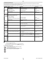
Gefahrenstelle
Gefährdungsart
Gefährdungsminderung
Wasserleitungen
Verletzung durch hohen Druck
Rohrleitungen vor Montage, Instandhaltung, Ausserbetriebnahme druck- und mediumfrei machen!
1.3.3 Elektrische Restgefahren
Im normalen Betrieb resultiert aus der elektrischen Ausrüstung der Armatur keine Gefahr.
Lediglich unter folgenden Voraussetzungen können Gefahren auftreten.
Gefahrenstelle
Gefährdungsart
Gefährdungsminderung
Verletzung von Kabeln
Lebensgefahr !
Elektroschock 230/400V
durch elektrische Spannung
Schutzleitersystem anschließen!
Bei Wartungs- und Instandsetzungsarbeiten Spannungsversorgung immer abschalten und gegen Wiedereinschalten sicher!
Die geltenden Unfallverhütungs- und Sicherheitsbestimmungen für elektrische Geräte beachten!
Elektrostatisch gefährdete Das Gerät enthält elektronische Bauelemente, die gegen elektrostaBauelemente / Baugruppen tische Entladung (ESD) empfindlich reagieren. Berührung mit elektrostatisch aufgeladenen Personen oder Gegenständen gefährdet
diese Bauelemente. Im schlimmsten Fall werden sie sofort zerstört
oder fallen nach der Inbetriebnahme aus.
1.3.4 Thermische Gefahren
Gefahrenstelle
Gefährdungsart
Anforderungen nach EN 100 015 - 1 beachten, um die
Möglichkeit eines Schadens durch schlagartige elektrostatische Entladung zu minimieren bzw. zu vermeiden!
Elektronische Bauelemente nicht bei anliegender Versorgungsspannung berühren!
Gefährdungsminderung
Heiße Oberfläche des Ventil- Verbrennen bei Berührung
körpers
Persönliche Schutzausrüstung tragen!
1.3.5 Chemische Restgefahren
Im normalen Betrieb resultiert vom Armatur keine chemische Gefahr.
Lediglich unter folgenden Voraussetzungen können Gefahren auftreten.
Gefahrenstelle
Gefährdungsart
Gefährdungsminderung
Verwendung von Reinigungsmitteln
Gefahr durch Kontakt mit oder Einatmung von gefährlichen Flüssig- Persönliche Schutzausrüstung tragen!
keiten, Gasen, Nebeln, Dämpfen oder Stäuben
Sicherheitsdatenblatt vom Reinigungsmittelhersteller
beachten!
1.4 Grundlegende Sicherheitsmaßnahmen
1.4.3 Veränderungen an der Armatur
Bei fremdbezogenen Teilen ist nicht gewährleistet, dass diese beanspruchungs- und sicherheitsgerecht konstruiert und gefertigt sind.
An der Armatur dürfen aus Sicherheitsgründen keine eigenmächtigen
Veränderungen vorgenommen werden.
Teile und Sonderausstattungen, die nicht von Honeywell geliefert wurden,
sind auch nicht von Honeywell zur Verwendung freigegeben.
1.4.1 Informationen verfügbar halten
Diese Bedienungsanleitung ist aufzubewahren. Es muss gewährleistet sein,
dass alle Personen, die Tätigkeiten an der Armatur auszuführen haben, die
Bedienungsanleitung jederzeit einsehen können.
1.4.2 Für den Umweltschutz
Bei allen Arbeiten an und mit der Armatur sind die Vorschriften zur
Abfallvermeidung und zur ordnungsgemäßen Abfallverwertung- bzw.
beseitigung einzuhalten.
Insbesondere ist darauf zu achten, dass Grundwasser gefährdende
Stoffe - wie Fette, Öle, Kühlmittel, lösungsmittelhaltige Reinigungsflüssigkeiten u. ä. - nicht den Boden belasten oder in die Kanalisation
gelangen. Diese Stoffe müssen in geeigneten Behältern aufgefangen,
aufbewahrt, transportiert und entsorgt werden.
Honeywell GmbH
3
MU1H-1551GE23 R0812
D
2. Funktionsbeschreibung
1.5 Sorgfaltspflicht des Betreibers
Diese Armatur wurde unter Berücksichtigung einer Risikobeurteilung und
nach sorgfältiger Auswahl der einzuhaltenden harmonisierten Normen,
sowie weiterer technischer Spezifikationen konstruiert und gebaut. Sie
entspricht damit dem Stand der Technik und gewährleistet ein Höchstmaß
an Sicherheit.
Diese Sicherheit kann in der betrieblichen Praxis jedoch nur dann erreicht
werden, wenn alle dafür erforderlichen Maßnahmen getroffen werden. Es
unterliegt der Sorgfaltspflicht des Betreibers der Armatur, diese Maßnahmen
zu planen und ihre Ausführung zu kontrollieren.
Der Betreiber muss insbesondere sicherstellen, dass
• die Armatur nur bestimmungsgemäß verwendet wird
• die Armatur nur in einwandfreiem, funktionstüchtigem Zustand betrieben
wird.
• erforderliche persönliche Schutzausrüstungen für das Bedienungs-,
Wartungs- und Reparaturpersonal zur Verfügung stehen und benutzt
werden.
• die Bedienungsanleitung stets in einem leserlichen Zustand und vollständig am Einsatzort der Armatur zur Verfügung steht.
• nur ausreichend qualifiziertes und autorisiertes Personal die Armatur
montiert, in Betrieb nimmt, bedient, instand hält und ausser Betrieb
nimmt.
• dieses Personal regelmäßig in allen zutreffenden Fragen von Arbeitssicherheit und Umweltschutz unterwiesen wird, sowie die Bedienungsanleitung und insbesondere die darin enthaltenen Sicherheitshinweise gelesen
und verstanden hat.
• keine an der Armatur angebrachten Sicherheits- und Warnhinweise
entfernt werden und alle leserlich bleiben.
• in einer Gefährdungsbeurteilung (im Sinne des Arbeitsschutzgesetzes §
5) die weiteren Gefahren ermittelt werden, die sich durch die speziellen
Arbeitsbedingungen am Einsatzort der Armatur ergeben.
• in einer Betriebsanweisung (im Sinne der Arbeitsmittelbenutzungsverordnung § 6) alle weiteren Anweisungen und Sicherheitshinweise zusammengefasst werden, die sich aus der Gefährdungsbeurteilung ergeben
haben.
2.1 Bestimmungsgemäße Verwendung
Bei nicht bestimmungsgemäßem Einsatz der Armatur können Gefahren für
Personen, Anlagen in der Umgebung und die Umwelt entstehen.
• Einsatz in geschlossenen Mediensystemen im Innenbereich (z.B. Heizkreisläufe) .
• Zur Überwachung und Aufrechterhaltung des Systemdrucks innerhalb der
definierten Grenzen.
• Einsatz nur in Verbindung mit von Honeywell empfohlenen bzw. zugelassenen Fremdgeräten und -komponenten.
• Zur Ankopplung des zu füllenden Mediensystems an eine Trinkwasserleitung ist ein geeigneter Systemtrenner gemäß EN1717 vor zu schalten.
• Geeigneten Filter gegen Partikel ≥ 600μm vorschalten.
2.2 Nicht bestimmungsgemäße Verwendung
Die Armatur ist nicht für den Einsatz im Außenbereich konzipiert. Temperatur-, Licht und Feuchtigkeitseinflüsse können zu Funktionsstörungen und
Geräteschäden führen.
• Armatur nicht im Außenbereich einsetzen.
• 230V-Steckernetzteil nur im trockenen Innenbereich betreiben.
• Armatur nur mit zugelassenem Honeywell Netzteil betreiben.
• Armatur nur bestimmungsgemäß einsetzen.
• Keine aggressiven oder brennbaren Medien in die Medienanschlüsse des
Systems einfüllen.
• Gehäuse nicht mechanisch belasten (z. B. durch Ablage von Gegenständen oder als Trittstufe).
• Armatur und Netzgerät nicht abdecken, um einen Wärmestau zu
vermeiden.
• Keine äußerlichen Veränderungen an den Gerätegehäusen vornehmen.
Gehäuseteile und Schrauben nicht lackieren!
• Armatur nicht über den für Installation und Wartung vorgesehenen Grad
hinaus demontieren.
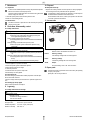
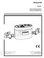
2.3 Aufgabe
Die Nachfüllkombination überwacht kontinuierlich den Druck in einem angeschlossenen System, z.B. einem Heizkreislauf und erhält ihn automatisch
aufrecht.
2.3.1 Funktion
Ein Sensor überwacht den Druck in dem angeschlossenen System kontinuierlich.
Fällt er unter einen einstellbaren Grenzwert, so wird ein Ventil geöffnet, dass
das System über eine angeschlossene Medienversorgung automatisch
solange nachspeist, bis ein vorgegebener Wert erreicht ist.
Darüber hinaus verfügt die Nachfüllkombination über einen Modus zur Erstbefüllung von Systemen.
Während der Befüllung wird auch der Druckanstieg überwacht. Falls dieser
z.B. durch eine Leckage im System ausbleibt, wird die Befüllung automatisch abgebrochen.
Ein weiterer Sensor erfasst das Volumen, das über die Nachfüllkombination
dem System zugeführt wurde ("Totalizer-Funktion"). Der aktuelle Wert wird
stündlich stromausfall-sicher gespeichert. Etwaige Änderungen seit dem
letzten Speichervorgang können nach einem Spannungsreset zu einem
etwas geringeren Anzeigewert führen. Durch Überwachung des Wertes
besteht die zusätzliche Möglichkeit, "schleichende" Verluste im System zu
erfassen. Der Totalizer-Wert kann manuell auf Null zurück gesetzt werden.
Die Bedienung des Geräts erfolgt über 3 Tasten, eine 7-Segmentanzeige
sowie 3 Status-LEDs.
Auftretende Störungen werden optisch und akustisch signalisiert. Über
einen Relais-Kontakt besteht optional die Möglichkeit, auftretende
Störungen weiter zu melden.
1.6 Anforderungen an das Bedienungspersonal
1.6.1 Bedienungspersonal
Diese Armatur darf nur von Personen montiert, in Betrieb genommen,
bedient, instand gehalten und ausser Betrieb genommen werden, die dafür
ausgebildet, eingewiesen und befugt sind.
Die jeweiligen Befugnisse des Personals sind vom Betreiber in Form einer
Betriebsanweisung klar festzulegen.
Darüber hinaus sind für folgende Tätigkeiten besondere Qualifikationen
erforderlich:
• Arbeiten an der elektrischen Ausstattung dürfen nur von Elektrofachkräften durchgeführt werden.
• Montage-, Wartungs-, Instandhaltungs- und Reparaturarbeiten dürfen nur
von qualifiziertem Fachpersonal ausgeführt werden
Die grundlegenden Vorschriften über Arbeitssicherheit und Unfallverhütung
sind zu beachten.
1.6.1.1 Qualifiziertes Personal
Qualifiziertes Fachpersonal sind Personen, die auf Grund ihrer Ausbildung,
Erfahrung und Unterweisung sowie ihrer Kenntnisse über einschlägige
Normen, Bestimmungen, Unfallverhütungsvorschriften und Betriebsverhältnisse, von dem für die Sicherheit der Anlage Verantwortlichen berechtigt
worden sind, die jeweils erforderlichen Tätigkeiten auszuführen und dabei
mögliche Gefahren erkennen und vermeiden können. Unter anderem sind
Kenntnisse über Erste-Hilfe-Maßnahmen und die örtlichen Rettungseinrichtungen erforderlich.
1.7 Persönliche Schutzausrüstung
Für den Betrieb der Armatur sind keine persönlichen Schutzausrüstungen
notwendig.
Honeywell GmbH
4
MU1H-1551GE23 R0812
D
2.4 Allgemeine Informationen
2.4.3 Aufbewahrung und Vollständigkeit
Diese Anleitung ist ein Bestandteil der Armatur und muss jederzeit vollständig zur Verfügung stehen. Eine fehlende Anleitung oder fehlende Seiten
müssen umgehend ersetzt werden.
2.4.4 Abbildungen
Die verwendeten Abbildungen sind Beispiele einer möglichen Armaturausführung und können im Einzelfall von der tatsächlichen Armaturausführung
abweichen.
2.4.5 Verwendete Symbole
1. Beginn einer Tätigkeitsbeschreibung
2. Nächster Arbeitsschritt
- Ergebnis einer Handlung
• Auflistung mehrerer Möglichkeiten
Verweis auf andere Dokumente
2.4.1 Konformität mit folgenden Normen
EMV-Richtlinie 2004/108/EG (nur bei korrekt angeschlossenem Kabel bzw.
Stecker und Buchsen)
Niederspannungsrichtlinie 2006/95/EG
2.4.2 Gewährleistung und Haftung
Grundsätzlich gelten die Allgemeinen Verkaufs-und Lieferbedingungen der
Firma Honeywell. Gewährleistungs-und Haftungsansprüche bei Personenund Sachschäden sind ausgeschlossen, wenn sie auf eine oder mehrere der
folgenden Ursachen zurückzuführen sind.
• Nicht bestimmungsgemäße Verwendung der Armatur
• Unsachgemäßes Montieren, Inbetriebnehmen, Bedienen und Warten der
Armatur
• Nichtbeachten der Hinweise in der Bedienungsanleitung bezüglich Transport, Lagerung, Montage, Inbetriebnahme, Betrieb, Wartung und Instandhaltung der Armatur
• Eigenmächtige bauliche Veränderungen an der Armatur
• Mangelhafte Überwachung von Teilen, die einem Verschleiß unterliegen
• Unsachgemäß durchgeführte Reparaturen
• Katastrophenfälle durch Fremdkörpereinwirkung und höhere Gewalt
Piktogramm
Gefahrenklassifikation
Gefahrenquelle
ª Folge bei Nichtbeachtung
Vermeidung
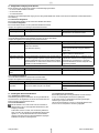
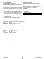
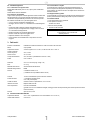
3. Technische Daten
Einbaulage
Einbau in waagerechte Rohrleitungen mit Bedieneinheit nach oben
Medium
Trinkwasser
Mediumstemperatur Eingangsseitig: 5 °C bis 30 °C, Ausgangsseitig: 5 °C bis 65 °C
Druckbereich
Eingangsseitig
Ausgangsseitig
0,1 bis 6 bar
1,0 bis 4 bar
Totalizer-Bereich
0,1 Liter bis 99 m³ (Anzeige zweistellig + Einheit)
Durchflussleistung Max. ca. 800 l/h
Abmessungen
225 x 115 x 143 mm (L x B x H)
Gewicht
ca. 1,8 kg
Gehäusematerial
entzinkungsbeständiges Messing
Dichtungsmaterial
EPDM
Anschlüsse
2x Außengewinde 1/2"
(1 Adapter beiliegend für Innengewinde 3/4")
Spannung
12 V DC über mitgeliefertes Weitbereichs-Steckernetzteil
Leistungsaufnahme < 3 W Ruheaufnahme
max. 12 W (Ventil geöffnet)
Alarmkontakt
Potentialfreier Schließer, 24V / 2A max.
Service-Schnittstelle Mini-USB-Buchse, Form "B"
Schutzart
IP 54 nach EN 60529
(gewährleistet nur bei korrekt angeschlossenem Kabel, korrekter Installation der Dämmschalenelemente und waagerechter Einbaulage)
Anschlüsse
Hohlstecker 5,5 mm
3.1 Zulässige Umgebungsbedingungen
Umgebungstemperatur
5 °C bis 50 °C (Netzteil und -kabel: 0 °C bis 40 °C)
Relative Luftfeuchtigkeit
max. 80% r.F.
Honeywell GmbH
5
MU1H-1551GE23 R0812
D
4. Montage
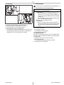
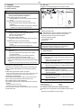
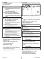
4.1.3 Arbeitschritte
Einbau in waagerechte Rohrleitungen mit Bedieneinheit nach oben
4.1 Einbau in Rohrleitung
2.
2.
4.1.1 Sicherheitshinweise
Gefahr
Gefahren für Personen, Anlagen in der Umgebung und die Umwelt
durch nicht bestimmungsgemäßen Einsatz der Armatur.
Armatur nur bestimmungsgemäß einsetzen.
Verletzungsgefahr durch hohen Druck in der Anlage.
Rohrleitungen vor Montage der Armatur druck- und mediumsfrei machen.
Gefahr durch unkontrollierten Anlauf der Anlage
Während der Installation ist die Anlage vor unbeabsichtigter
Betätigung zu sichern.
Nach einer Unterbrechung der elektrischen oder fluidischen
Versorgung ist ein definierter oder kontrollierter Wiederanlauf
des Prozesses zu gewährleisten.
3.
4.
Trinkwasserabsicherung nach DIN EN 1717 beachten
v
1. Rohröffnungsbreite ermitteln
Warnung
Platzbedarf für Betrieb und Instandhaltung berücksichtigen.
Platzbedarf für vorgeschalteten Systemtrenner ermitteln.
Die Armatur ist nicht für den Einsatz im Außenbereich konzipiert.
ª Temperatur-, Licht und Feuchtigkeitseinflüsse können zu Funkti-
onsstörungen und Geräteschäden führen.
Die Armatur nicht im Außenbereich einsetzen.
Gefahr durch unsachgemäße Installation
Durchführung nur durch qualifiziertes Personal (siehe Kapitel
1.6.1.1).
Verbrennungsgefahr durch hohe Medientemperaturen.
Rohrleitungen vor Montage der Armatur druck- und mediumsfrei machen.
Anlage vor Montage der Armatur abkühlen lassen.
2. Absperrkugelhähne ein- und ausgangsseitig in Rohrleitung einbauen
3. Systemtrenner vorschalten
- Anschlussadapter verwenden
4. Nachfüllkombination einbauen
Vorsicht
Einbau in waagrechte Rohrleitung
Durchflussrichtung beachten (Richtungspfeil auf dem Armaturen-
körper)
Spannungs- und biegemomentfrei einbauen.
Vorsicht
4.2 Elektrischer Anschluss
Beschädigte oder falsch eingebaute Armatur.
ª Fehlfunktionen
Armatur nicht beschädigen und nur in sauberem, funktionstüch-
4.2.1 Sicherheitshinweise
Gefahr
tigem Zustand einbauen.
Armatur gemäß der beschriebenen Anordnung einbauen.
Spannungs- und biegemomentfrei einbauen.
Für den Installationsvorgang sind einzelne Gehäuseteile abzunehmen, wodurch der IP-Schutz des Gerätes nicht mehr vollständig
besteht.
Während der Montage darf kein Wasser in das Geräteinnere
eindringen.
Verletzungsgefahr durch elektrische Spannung.
ª Hohe Körperströme und Verbrennungen durch direkte und indi-
rekte Berührung von unter Spannung stehenden Teilen.
Spannungsversorgung vor Montage der Armatur abschalten
und gegen Wiedereinschalten sichern.
Nicht oder fehlerhaft angeschlossene Kabel
ª Fehlfunktionen, welche die Sicherheit des Bedienpersonals
gefährden.
Arbeiten an der elektrischen Ausstattung dürfen nur von Elektrofachkräften durchgeführt werden.
Falsch verdrahtete Anschlüsse
ª Zerstörung elektrischer / elektronischer Bauteile.
Arbeiten an der elektrischen Ausstattung dürfen nur von Elektrofachkräften durchgeführt werden.
Unsachgemäß verlegte Leitungen (z. B. zu kleiner Biegeradius)
ª Schmor- und Kabelbrände.
Arbeiten an der elektrischen Ausstattung dürfen nur von Elektrofachkräften durchgeführt werden.
Spannungsführende Kabelenden und Bauteile
Durchgehende Verbindung des Schutzleitersystems muss
vorhanden sein.
4.1.2 Einbauhinweise
• Ein- und ausgangsseitig Absperrarmaturen einbauen
• Zur Ankopplung des zu füllenden Mediensystems an eine Trinkwasserleitung geeigneten Systemtrenner (optional erhältlich) vorschalten
• Geeigneten Filter gegen Partikel ≥ 600μm vorschalten
- Nachfüllkombination wird vor Funktionsstörungen und Korrosionsschäden durch
eingespülte Fremdkörper, z.B. Schweißperlen, Dichtungsmaterial, Späne oder
Rost geschützt
• Einbau in waagrechte Rohrleitung
• Der Einbau darf nicht in Räumen oder Schächten erfolgen, in denen
giftige Gase oder Dämpfe auftreten und die überflutet werden können
(Hochwasser)
• Der Einbauort muss gut belüftet sein
• Der Einbauort muss frostsicher und gut zugänglich sein
4.2.2 Anschlussdaten
Spannungsversorgung Armatur
12V DC
Spannungsversorgung Steckernetzteil 230V AC
4.2.3 Benötigte Hilfsmittel (bauseits)
Folgende Hilfsmittel und Komponenten sind bauseits bereit zu stellen:
• fachgerechte Installation der Stromversorgung
- Vereinfacht Wartung und Reinigung
- Display am Gerät kann gut beobachtet werden
• Beruhigungsstrecke von mindestens 5xDN nach Nachfüllkombination
vorsehen (entsprechend DIN 1988, Teil 5)
Honeywell GmbH
6
MU1H-1551GE23 R0812
D
5. Inbetriebnahme
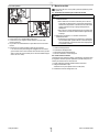
4.2.4 Arbeitschritte
Durchführung nur durch qualifiziertes Personal (siehe Kapitel 1.6.1.1).
5.1 Sicherheitshinweise für die Inbetriebnahme
Warnung
2.
Gefahr durch unsachgemäßen Betrieb.
ª Fehlfunktionen
Vor der Inbetriebnahme ist die Bedienungsanleitung vom
4.
Bediener sowie vom zuständigen Fachpersonal/Betreiber zu
lesen und muss ständig am Einsatzort der Armatur oder Anlage
verfügbar sein.
Für die Inbetriebnahme der Armatur sind die örtlichen Sicherheits- und Unfallvorschriften einzuhalten.
Beschädigte oder falsch eingebaute Armatur.
ª Fehlfunktionen
Armatur auf sichtbare Schäden überprüfen; festgestellte
Mängel sofort beseitigen oder dem Aufsichtspersonal melden.
Die Armatur darf nur in einwandfreiem Zustand betrieben
werden.
3.
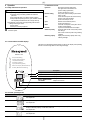
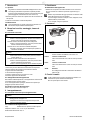
1. Dämmschalen abnehmen
2. Hohlstecker des Steckernetzteils in die Buchse stecken
3. Kabel Alarmsignal durch die Zugentlastung führen (optional)
4. Kabel Steckernetzteil durch die Zugentlastung führen
5. Dämmschalenhälften wieder vorsichtig anbringen
- Die Kabel müssen in dem dafür vorgesehenen Ausschnitt liegen und die
Dämmschalenhälften spaltfrei sitzen (die rechte und linke Dämmschalenhälfte passen nur in einer Ausrichtung auf die Armatur)
Machen Sie sich ausreichend vertraut mit
• der Ausstattung der Armatur
• der Arbeitsweise der Armatur
• dem unmittelbaren Umfeld der Armatur
• den Maßnahmen für einen Notfall
5.2 Erstinbetriebnahme
Die Armatur wurde werkseitig eingestellt und kann nach erfolgtem Einbau
und Erledigung aller Vorarbeiten einem Probelauf zur Funktionskontrolle
unterzogen werden.
1. Hauptschalter der Spannungsversorgung einschalten
2. Steckernetzteil einstecken
- nur feuchtigkeitsgeschütze Steckdose (IP54) verwenden
3. Verschraubungen auf Dichtheit prüfen
Honeywell GmbH
7
MU1H-1551GE23 R0812
D
6. Betrieb
6.2 Begriffsdefinitionen
Hysterese
Band um den Solldruck in bar.
Die Obergrenze errechnet sich aus
Solldruck+(Hysterese/2)
werkseitig voreingestellt auf 0,2 bar
Solldruck
Solldruck der Anlage
werkseitig voreingestellt auf 2 bar
Maximale Füllzeit
Zeit, in der die Anlage den oberen Druckwert bei
der Nachspeisung erreichen muss
werkseitig voreingestellt auf 15 min
Überwachungszyklus Anzahl der Messungen je Stunde
werkseitig voreingestellt auf 2
Wasserverbrauch
Gesamtwasserverbrauch der Anlage. Dient der
Erkennung von Systemleckagen
Bereichsüberschreitung Obergrenze des messbaren Wasserverbrauches
Mengenabschaltung
Abschaltung nach Durchfluss einer bestimmten
Wassermenge
Diese Funktion wird bei Verwendung von Enthärtungskartuschen benötigt
Restkapazität
Anzeige der Restkapazität bei Verwendung von
Enthärtungskartuschen
6.1 Sicherheitshinweise für den Betrieb
Warnung
Gefahr durch unsachgemäße Bedienung
Bedienung nur durch ausreichend qualifiziertes und autori-
siertes Personal.
Armatur nur in einwandfreiem, funktionstüchtigem Zustand
betreiben.
Bedienungsanleitung stets in einem leserlichen Zustand und
vollständig am Einsatzort der Armatur zur Verfügung halten
Heiße Rohrleitungen oder Armaturoberflächen durch Betrieb mit
heißen Medien
ª Verbrennen bei Berührung.
Berührung vermeiden.
Persönliche Schutzausrüstung tragen.
Beim Schließen des Ventils der Nachfüllkombination kann unter
Umständen im Leitungssystem ein "Schließschlag-Geräusch"
entstehen.
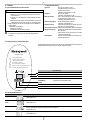
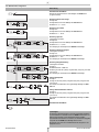
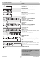
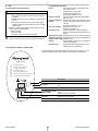
6.3 Bedienelemente und LED-Anzeigen
Die Nachfüllkombination wird über drei Tasten auf der Oberseite bedient. Die Anzeige der
Betriebszustände erfolgt über LEDs und Sieben-Segment-Anzeige.
NK300T-1/2A
Error (Fehlermeldung)
Pressure Setting (Solldruck)
Time (Maximale Füllzeit)
Hysteresis (Hysterese)
Cycle (Überwachungszyklus)
Water Consumption (Wasserverbrauch)
Overflow (Bereichsüberschreitung)
Beschreibung
☞
Auto / Liter
Fill / Liter x 102
Config / Liter x 103
ENTER
PN : 10 bar
PIN : Pmin max 0,1...6,0 bar
POUT : Pmin max 1,5...4,0 bar
Tfill : Tmin max 1...30 min.
Supply voltage 12V DC ---o-o-o
LED grün
Anzeige Automatikmodus
LED gelb
Anzeige Füllmodus / Anlagenfüllung
LED rot
Anzeige Konfigurationsmodus
Taster HAND/
AUTOMATIK/
ENTER
Wechsel zwischen Automatik- und Konfigurationsmodus
Übernahme der eingestellten Werte
Taster AB
Einstellwerte verringern
Taster AUF
Einstellwerte erhöhen
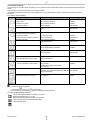
6.4 Übersicht Betriebsmodi
Modus
AUTOMATIK
Anzeige
Beschreibung
Der Druck der Anlage wird gemessen.
siehe Kapitel 6.4.1
ANLAGENFÜLLUNG
Die Anlage wird befüllt
siehe Kapitel 6.4.2
KONFIGURATION
Einstellen der Parameter Solldruck, Füllzeit, Hysterese, Zykluszeit, Mengenbegrenzer
Anzeige verbleibende Restmenge Zählerstand Wasserverbrauch
siehe Kapitel 6.4.3
Anzeige des Fehlercodes
siehe Kapitel 6.4.4
STÖRUNG
Honeywell GmbH
8
MU1H-1551GE23 R0812
D
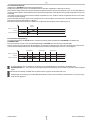
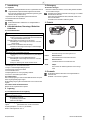
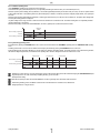
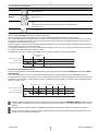
6.4.1 Betriebsmodus Automatik
Im Betriebsmodus AUTOMATIK wird der Druck der Anlage gemessen.
Der Messzyklus (Messungen je Stunde) ist ein einstellbarer Parameter (werkseitig voreingestellt auf 2 Messungen pro Stunde).
Wird der Solldruck (abzgl. Hysterese/2) der Anlage unterschritten (einstellbarer Parameter, werkseitig voreingestellt auf 2,0 bar), wird das Ventil geöffnet und
die Anlage mit Wasser gefüllt. In diesem Betriebszustand leuchtet zusätzlich die gelbe LED und der Fließdruck wird angezeigt (Anzeige blinkt). Der Druck der
Anlage steigt.
Ist der Solldruck zuzüglich einer Hysterese/2 erreicht (werkseitig voreingestellt auf 0,2 bar), schaltet das Ventil ab. Die gelbe LED erlischt und es wird wieder
der Fülldruck der Anlage angezeigt.
Dauert das Nachfüllen der Anlage zu lange, wird das Ventil geschlossen und das Gerät geht in einen Störungsmodus. Die maximale Füllzeit ist ein einstellbarer Parameter (werkseitig voreingestellt auf 15 Minuten).
Bei Erreichen einer Gesamtverbrauchmenge von 99999 Litern wird generell ein Alarm ausgelöst, welcher quitiert werden muss.
Füllzeit
(begrenzt)
Hysterese
Solldruck + Hysterese/2
Solldruck
Solldruck - Hysterese/2
Systemdruck
Fließdruck
6.4.2 Betriebsmodus Anlagenfüllung
Durch gleichzeitiges Betätigen der AUF-/AB-Tasten für 5 Sekunden wechselt das Gerät vom Betriebsmodus AUTOMATIK in den Betriebsmodus
ANLAGENFÜLLUNG.
Der Füllvorgang dauert 2 Stunden und ist durch gleichzeitiges Betätigen der AUF-/AB-Tasten für 5 Sekunden manuell abschaltbar.
Während des Füllvorgangs leuchtet die gelbe LED. Der Fließdruck wird angezeigt, die Anzeige blinkt. Der Systemdruck wird während dieser Zeit nicht überwacht, die maximale Füllzeit (Parameter) ist in diesem Betriebszustand nicht relevant. Die Füllzeit ist jedoch auf max. 2 Stunden begrenzt.
Beruhigungszeit
Beruhigungszeit
Beruhigungszeit
Hysterese
Solldruck + Hysterese/2
Solldruck
Solldruck - Hysterese/2
Fließdruck
max. 2h
Je nach Anlagenaufbau kann es vorteilhaft sein, den Solldruck an der Nachfüllkombination vor dem Wechsel in den Betriebsmodus
ANLAGENFÜLLUNG um ca. 10% zu reduzieren. Nach erfolgreich abgeschlossener Befüllung kann dann wieder der gewünschte Solldruck eingestellt
werden.
Bei Erreichen einer Füllmenge von 99999 Litern wird generell ein Alarm ausgelöst, welcher quitiert werden muss.
Nach Beendigen des Füllvorgangs muss die Nachfüllkombination NK300-T wieder in den Automatikmodus geschaltet werden, da sonst der Leckageschutz nicht mehr gegeben ist.
Honeywell GmbH
9
MU1H-1551GE23 R0812
D
6.4.3 Betriebsmodus Konfiguration
Beschreibung
Betriebsmodus AUTOMATIK
Wechsel ins Konfigurationsmenü durch Betätigen der ENTER-Taste
(5s gedrückt halten)
5s
ENTER
ENTER
Einstellung Solldruck der Anlage
Anzeige in bar
Anzeige blinkt bis zum ersten Betätigen der AUF-/AB-Taste
Einstellbar von 1,0 ... 4,0 bar
ENTER
Einstellung max. Füllzeit
Anzeige in min
Anzeige blinkt bis zum ersten Betätigen der AUF-/AB-Taste
Einstellbar von 1 ... 30 min
ENTER
ENTER
Einstellung Hysterese
Codeeingabe* erforderlich
Anzeige in bar
Anzeige blinkt bis zum ersten Betätigen der AUF-/AB-Taste
Einstellbar von 0,1 ... 0,6 bar
Zum Überspringen des Menüpunkts die ENTER-Taste betätigen
5s
ENTER
ENTER
ENTER
ENTER
ENTER
Einstellung Überwachungszyklen
Codeeingabe* erforderlich
Anzeige in x/h
Anzeige blinkt bis zum ersten Betätigen der AUF-/AB-Taste
Einstellbar von 1 ... 6 x/h
Zum Überspringen des Menüpunkts die ENTER-Taste betätigen
5s
ENTER
ENTER
ENTER
ENTER
ENTER
Einstellung Mengenabschaltung
Codeeingabe* erforderlich
Anzeige in l
Einstellbarer Bereich 1-9999 Liter
Einstellung: bei roter LED (1000er), bei gelber LED (100er), bei grüner LED
(10er und 1er)
Zum Überspringen des Menüpunkts die ENTER-Taste betätigen
5s
ENTER
ENTER
ENTER
ENTER
ENTER
ENTER
ENTER
Anzeige Restkapazität
Anzeige in l
Anzeige: bei roter LED (1000er), bei gelber LED (100er), bei grüner LED
(10er und 1er)
Zurücksetzen des Zählerstands durch gleichzeitiges Betätigen der AUF-/
AB-Taste
5s
l
l
ENTER
hl
ENTER
hl
ENTER
m3
m3
Anzeige Zählerstand Wasserverbrauch
Anzeige in l
Anzeige: bei roter LED (1000er), bei gelber LED (100er), bei grüner LED
(10er und 1er)
Zurücksetzen des Zählerstands durch gleichzeitiges Betätigen der AUF-/
AB-Taste
5s
l
ENTER
hl
ENTER
m3
Betriebsmodus AUTOMATIK
*Codeeingabe
Zur Aktivierung eines Menüpunkts, für den eine Codeeingabe erforderlich
ist, eine Pfeiltaste und unmittelbar danach die ENTER-Taste drücken und
beide 5s gedrückt halten. Danach Sicherheitscode (85) eingeben.
Der Sicherheitscode besteht aus zwei Ziffern, die nacheinander eingegeben
und jeweils mit der ENTER-Taste bestätigt werden müssen.
Bei falschem Code oder nach 10s Wartezeit kehrt das Programm in das
Hauptmenü zurück.
Honeywell GmbH
10
MU1H-1551GE23 R0812
D
6.4.4 Betriebsmodus Störung
Tritt eine Störung auf, erscheint im Display die Anzeige „Er“ (Error) im Wechsel mit dem entsprechenden Fehlercode. Letzter Zustand der Status-LED bleibt
erhalten
Gleichzeitig ertönt der akustische Warnmelder und das Relais wird betätigt.
Nach Betätigen der ENTER-Taste erlischt die akustische Warnmeldung und das Relais fällt ab. Die Anzeige „Er“ bleibt jedoch erhalten, bis die Störung
behoben ist.
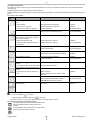
6.4.4.1 Störung - Ursache - Behebung
Fehlercode
Ursache
Behebung
Ausführung durch
Gerät zur Reparatur einsenden
Installateur
Messwert am Drucksensor zu gering
• Sensor defekt
• Kabelbruch am Sensor
Gerät zur Reparatur einsenden
Installateur
• Gerät falsch kalibriert
Gerät neu kalibrieren
Servicetechniker
Timeout beim Befüllen
Anlage auf Leckage untersuchen bzw. Wert für Füllzeit
erhöhen
Installateur
Servicetechniker
• Leckage am Ventilsitz
Gerät oder Anlage prüfen
• Rückdruck aus der Anlage beim Aufheizen
Gerät oder Anlage prüfen
Installateur
Servicetechniker
Fehlende Einstell-Werte
Gerät zur Reparatur einsenden
Installateur
Einstell-Werte einstellen
Servicetechniker
Systemdruck zu hoch (Der Systemdruck liegt
min. 0,8 bar über Sollwert + Hysterese/2)
Unzulässige Konfigurationsdaten
Gerät neu konfigurieren
Installateur
Gerät auf Werkseinstellung zurücksetzen
Installateur
Gerät zur Reparatur einsenden
Installateur
Gerät neu kalibrieren
Servicetechniker
Patronenwechsel steht an
----
• 100% des eingestellten Volumens erreicht
Patrone wechseln
Zählerstand Wasserverbrauch zurücksetzen
siehe Kapitel 6.4.3
Installateur
Timer / Erinnerungsfunktion
Inspektion veranlassen
Betreiber
Zurücksetzen durch gleichzeitiges Betätigen der AUF-/AB- Servicetechniker
Taste (5s gedrückt halten)
Bereichsüberschreitung
*aufsummierter Wert ist größer als 99m3
Zählerstand Wasserverbrauch zurücksetzen
siehe Kapitel 6.4.3
Fehlende Kalibrierdaten
*
Mengenabschaltung
• 90% des eingestellten Volumens erreicht
Mengenabschaltung
Installateur
Betreiber
* Die Anzeige blinkt im Wechsel
• Im Füllmodus:
und gelbe LED
• Im Automatikmodus: Istdruck (z. B.
) und grüne LED
Da hier eine Meldung und kein Fehler angezeigt wird, ertönt kein akustisches Warnsignal.
6.4.4.2 Gerät auf Werkseinstellung zurücksetzen
ENTER
Um das Gerät auf Werkseinstellung zurücksetzen, sind alle drei
Bedientasten gleichzeitig für 5 s zu drücken.
Nach erfolgreichem Rücksetzen wird im Display die FirmwareVersion solange angezeigt, wie die Bedientasten weiterhin
gedrückt gehalten werden.
Honeywell GmbH
11
MU1H-1551GE23 R0812
D
7. Instandhaltung
10. Entsorgung
7.1 Inspektion
10.1 Armatur entsorgen
1. Alle Teile und Hilfsstoffe sortenrein und nach örtlich geltenden Richtlinien
und Vorschriften entsorgen.
Um einen zuverlässigen Betrieb der Armatur zu gewährleisten sind die
vorgeschriebenen Inspektionsarbeiten fristgemäß durchzuführen.
Dazu verfügt das Gerät über eine Timer/Erinnerungsfunktion (gelbe
LED blinkt, Anzeige Fehlercode 4.3)
B
1. Systemdruck unter den eingestellten Hysteresewert absenken
2. Korrekte Nachfüllfunktion beobachten
7.2 Wartung
Unbedingt die Vorschriften und Gesetze zur Entsorgung von umweltbelastenden Stoffen beachten.
Solche Stoffe sind beispielsweise Altöle, Kühlmittel, Farben, Kunststoffe und Chemikalien.
Im Zweifel mit dem Hersteller in Verbindung setzen.
11. Zubehör
Die Nachfüllkombination enthält keine vom Anlagenbetreiber zu
wartenden Teile.
8. Außerbetriebnahme, Demontage, Wiederinbetriebnahme
8.1 Sicherheitshinweise
Gefahr
VE300
Verletzungsgefahr durch elektrische Spannung.
Spannungsversorgung vor Demontage der Armatur abschalten
und gegen Wiedereinschalten sichern.
Verletzungsgefahr durch hohen Druck in der Anlage.
Rohrleitungen vor Demontage der Armatur druck- und medi-
umsfrei machen.
AD300
Gefahr durch unkontrollierten Anlauf der Anlage
Während der Demontage ist die Anlage vor unbeabsichtigter
P300-S/L
Betätigung zu sichern.
Warnung
VE300-1/2A Verschneideeinheit
Gefahr durch unsachgemäße Demontage
Durchführung nur durch qualifiziertes Personal (siehe Kapitel
Standardausführung mit Anschlussgewinde 1/2"
P300-S
1.6.1.1).
Verbrennungsgefahr durch hohe Medientemperaturen.
Rohrleitungen vor Demontage der Armatur druck- und mediumsfrei machen.
Anlage vor Demontage der Armatur abkühlen lassen.
Enthärter-Patrone
0,75l Enthärter-Patrone mit Ionentauscher-Harz
P300-L
Enthärter-Patrone
3,5l Enthärter-Patrone mit Ionentauscher-Harz
8.2 Armatur außer Betrieb setzen und demontieren
AD300
1. Rohrleitungen druck- und mediumsfrei machen
2. Anlage vor unbeabsichtigter Betätigung sichern
3. Stromzuführung spannungsfrei schalten
4. Armatur abkühlen lassen
5. Absperrkugelhähne ein- und ausgangsseitig schließen
6. Armatur aus der Rohrleitung demontieren
Adapter
Zum Anschluss der Enthärtungseinheit an 3/4" Aussengewinde
12. Ersatzteile
Die Nachfüllkombination enthält keine vom Anlagenbetreiber zu
wartenden Teile.
Ersatzteile / -sets sind nicht vorgesehen.
8.3 Armatur lagern
Eine kurzfristige Lagerung ist ohne besondere Maßnahmen bei den spezifizierten Umgebungsbedingungen möglich.
Bei längerfristiger Lagerung besondere Maßnahmen zum Korrosionsschutz
ergreifen.
8.4 Armatur wieder in Betrieb nehmen
Beachten Sie die Vorgehensweise in Kapitel 5.
9. Lagerung
9.1 Sicherheitshinweise für die Lagerung
Warnung
Unsachgemäße Lagerung
ª Beschädigung der Armatur
Lagerbedingungen beachten !
Nicht im Freien lagern !
9.2 Lagerbedingungen
Lagerort
geschlossener Raum, trocken und staubfrei
Umgebungstemperatur 5 °C bis 50 °C (inkl. Netzteil)
Relative Luftfeuchtigkeit max. 80% r.F.
Honeywell GmbH
12
MU1H-1551GE23 R0812
GB
Content
1. Safety Guidelines
1.
1.1
1.2
1.3
1.1 Safety instructions in this manual
Safety Guidelines ............................................................................ 13
Safety instructions in this manual ..................................................... 13
General safety instructions ............................................................... 13
Residual dangers in handling the tap ................................................ 14
1.3.1 Mechanical residual dangers ................................................... 14
1.3.2 Residual dangers pertaining to fluids ...................................... 14
1.3.3 Residual electrical hazards ..................................................... 14
1.3.4 Thermal hazards ..................................................................... 14
1.3.5 Residual chemical hazards ..................................................... 14
1.4 Basic Safety Measures ..................................................................... 14
1.4.1 Keep information available ...................................................... 14
1.4.2 For environmental protection ................................................... 14
1.4.3 Modifications to the tap ........................................................... 14
1.5 Duty of due care of the operator ....................................................... 15
1.6 Requirements for operating personnel .............................................. 15
1.6.1 Operating personnel ................................................................ 15
1.7 Personal safety equipment ............................................................... 15
2. Description of function ................................................................... 15
2.1 Intended use ..................................................................................... 15
2.2 Non-intended use .............................................................................. 15
2.3 Task .................................................................................................. 15
2.3.1 Function ................................................................................... 15
2.4 General information .......................................................................... 16
2.4.1 Conformity with the following norms ........................................ 16
2.4.2 Warranty and liability ............................................................... 16
2.4.3 Storage and perfect condition ................................................. 16
2.4.4 Illustrations .............................................................................. 16
2.4.5 Symbols ................................................................................... 16
3. Technical data ................................................................................. 16
3.1 Authorised environmental conditions ................................................ 16
4. Assembly ......................................................................................... 17
4.1 Installation into pipeline ..................................................................... 17
4.1.1 Safety instructions ................................................................... 17
4.1.2 Installation notes ..................................................................... 17
4.1.3 Work steps .............................................................................. 17
4.2 Electrical connection ......................................................................... 17
4.2.1 Safety instructions ................................................................... 17
4.2.2 Connection specifications ........................................................ 17
4.2.3 Required auxiliary aids (on site of operating company) .......... 17
4.2.4 Work steps .............................................................................. 18
5. Start-up ............................................................................................ 18
5.1 Safety instructions for start-up .......................................................... 18
5.2 Initial operation .................................................................................. 18
6. Operation ......................................................................................... 19
6.1 Safety instructions for operation ....................................................... 19
6.2 Definition of terms ............................................................................. 19
6.3 Control elements and LED displays .................................................. 19
6.4 Overview, operating modes .............................................................. 19
6.4.1 Automatic operating mode ...................................................... 20
6.4.2 System filling operating mode ................................................. 20
6.4.3 Configuration operating mode ................................................. 21
6.4.4 Malfunction operating mode .................................................... 22
7. Maintenance .................................................................................... 23
7.1 Inspection .......................................................................................... 23
7.2 Maintenance ..................................................................................... 23
8. Shut-down, disassembly, restart ................................................... 23
8.1 Safety instructions ............................................................................. 23
8.2 Shutting down the tap and disassembly ........................................... 23
8.3 Storing the tap ................................................................................... 23
8.4 Starting up the tap again ................................................................... 23
9. Lagerung .......................................................................................... 23
9.1 Safety instructions for storage .......................................................... 23
9.2 Storage conditions ............................................................................ 23
10. Disposal ........................................................................................... 23
10.1Disposal of the tap ............................................................................ 23
11. Accessories ..................................................................................... 23
12. Spare parts ...................................................................................... 23
Honeywell GmbH
Danger
Places with this sign signify that death, severe bodily injury or significant
property damage will occur if the appropriate precautionary measures
are not followed!
Warning
Places with this sign signify that death, severe bodily injury or significant
property damage may occur if the appropriate precautionary measures
are not followed!
Caution
Places with this sign signify that small bodily injury or slight property
damage may occur if the appropriate precautionary measures are not
followed!
Places with this sign provide technical information and tips on usage
that damage to the machine must be avoided.This symbol is not a
safety indication.
Places with this sign provide information about possible hazards to the
environment
Please notice that a safety symbol never can replace the text of the
safety instruction itself - the text of the safety instruction must be read
entirely!
1.2 General safety instructions
This manual contains basic instructions which are to be observed in transport, assembly, start-up, operation, maintenance, shut-down, storage and
waste disposal.
The following safety instructions are to be observed when operating the tap:
• When using the tap, the data, operation and usage conditions specifically
authorised in the technical specifications sheet and the operating manual
are to be observed.
• Prior to assembly and start-up, the operating manual of the operator and
of the specialist personnel/operating company in charge are to be read
and must be permanently accessible on site of the tap or the system.
• Installation and maintenance work may only be performed by authorised
specialist personnel with the appropriate tools.
• The technical state of the tap is to be checked at regular intervals (at least
once a year) by the operating company.
• The local safety and accident regulations are to be observed when operating the tap.
• The general technical rules must be observed when planning the usage
and operating the device.
• Any modification of the tap is prohibited and leads to the loss of all
warranty claims.
• After an interruption of the electrical or fluid supply, a defined or controlled
re-run of the process must be ensured.
13
MU1H-1551GE23 R0812
GB
1.3 Residual dangers in handling the tap
Usage of the tap involves hazards and adverse effects
• for the body and life of the operator or third person
• for the tap itself
• to other property.
Basis for the safe and appropriate handling and disturbance-free operation of this tap is the knowledge of the safety and user instructions in this manual.
1.3.1 Mechanical residual dangers
During normal operation, no danger is threatened from mechanical components.
1.3.2 Residual dangers pertaining to fluids
During normal operation, no danger is threatened by hydraulic components.
Hazards might result solely under the following conditions.
Danger area
Type of hazard
Reduction of hazard
Water pipes
Injury through high pressure
Clear pipelines of pressure and medium prior to assembly,
maintenance, shut-down!
1.3.3 Residual electrical hazards
During normal operation, no danger is threatened by the system's electrical equipment.
Hazards might result solely under the following conditions.
Danger area
Type of hazard
Reduction of hazard
Injury from cables
Danger to life !
Electric shock of 230/400V from electric voltage
Connect up protective earth system!
Always switch off power supply and secure against switching on again during maintenance and servicing work!
Comply with the valid accident prevention and safety regulations for electrical devices!
Electrostatically endangered The device contains electronic componental elements that react
components / subassemblies sensitively to electrostatic discharge (ESD). Contact with electrostatically charged persons or objects endangers these componental
elements. Worst case scenario: they will be immediately destroyed
or fail after start-up.
1.3.4 Thermal hazards
Danger area
Type of hazard
Comply with requirements according to EN 100 015 - 1, in
order to minimise or avoid damage through shock-type
electrostatic discharge!
Do not touch electronic componental elements when the
power supply is on!
Reduction of hazard
Hot surface of the valve body Burning at contact
Wear personal safety equipment!
1.3.5 Residual chemical hazards
During normal operation, no chemical danger is threatened by the tap.
Hazards might result solely under the following conditions.
Danger area
Type of hazard
Reduction of hazard
Use of detergents
Danger through contact with or breathing in dangerous fluids,
gases, fumes, vapours or dust
Wear personal safety equipment!
1.4 Basic Safety Measures
1.4.3 Modifications to the tap
When using externally procured parts, there is no guarantee that these are
designed and constructed to tolerate demands made upon them or whether
they comply with safety regulations.
For reasons of safety, no unauthorised modifications may be made to the
tap.
Parts and special equipment not delivered by Honeywell are also not authorised by Honeywell for use.
1.4.1 Keep information available
This operating manual is to kept in a safe place. It must be ensured that all
persons who have to work at the tap are able to consult the operating
manual at all times.
1.4.2 For environmental protection
When working on and with the tap, the regulations on waste avoidance
and legally prescribed waste recovery or disposal must be observed.
Particular attention must be paid that materials and agents dangerous
to the groundwater such as fats, oils, coolants, solvent-based liquid
detergents, etc. do not pollute the ground or access the sewage system.
These materials must be caught in suitable tanks, stored, transported
and properly disposed of.
Honeywell GmbH
Pay attention to the safety specifications sheet of detergent
manufacturers!
14
MU1H-1551GE23 R0812
GB
2. Description of function
1.5 Duty of due care of the operator
This tap was designed and constructed mindful of an assessment of the
hazards involved and with careful selection of the harmonised, prescribed
norms, also further technical specifications. It thus complies with state-ofthe-art technology and guarantees an optimal standard of safety.
This safety can only be attained in operational practice when all the required
measures have been taken. It is the responsibility of the operating company
of the tap to plan these measures and control their execution.
In particular, the operator must ensure that
• the tap is only used according to regulations
• the tap is operated only when it is in perfect, functioning condition.
• the required personal safety gear for operating, maintenance and repair
personnel is available and is used
• the operating manual is always kept in good, readable condition and is
completely accessible at the site of usage of the tap.
• the tap is assembled, started up, operated, maintained and shut down
solely by sufficiently qualified and authorised personnel.
• this personnel is regularly instructed in all relevant question of work safety
and environmental protection, and has also read and understood the
operating manual and particularly the safety instructions it contains.
• none of the safety and warning signs attached to the tap are removed and
all remain legible.
• in an assessment of hazards (according to the Safety at Work Act § 5),
the personnel shall be informed on further dangers which ensue because
of the special working conditions at the usage site of the tap.
• all further information and safety instructions which arise from the hazard
assessment process shall be summarised in operating instructions
(according to the work equipment regulation § 6).
2.1 Intended use
If used not according to intention, the tap can be a danger to persons,
systems in the surroundings and to the environment.
• Usage in closed media systems in interiors (e.g. heating circuits) .
• For monitoring and maintaining the system pressure within the defined
limits.
• Usage only in connection with components and external devices recommended and authorised by Honeywell.
• When filling and connecting up the media system with a drinking water
supply, a suitable system separator is to be set upstream according to
EN1717.
• Suitable filter against particles ≥ 600μm set upstream.
2.2 Non-intended use
The tap is not designed for outside usage. Temperature, light and moisture
influences can lead to malfunctions and damage to devices.
• Do not use the tap outside.
• Operate 230V plug only in dry interiors.
• Only operate the tap with authorised Honeywell power pack.
• Only use the tap as intended in regulations.
• Do not fill aggressive or flammable medium into the medium lines of the
system.
• No mechanical stress on housings (e.g. by depositing objects or as a
step).
• Do not cover the tap and power pack, so as to avoid heat build-up.
• Do not perform any external modifications on the device housing. Do not
paint housing parts and screws!
• Do not dismantle the tap more than the extent required by installation and
maintenance.
1.6 Requirements for operating personnel
1.6.1 Operating personnel
This tap may only be assembled, started up, operated, maintained and shut
down by persons who have been trained, instructed and authorised to do so.
The relevant authorisations of the personnel are to be specified by the
operating company in the form of an operating instruction.
Over and above this, special qualifications are required for the following
tasks:
• Only electricians may perform work on electrical equipment.
• Assembly, maintenance, servicing and repair work may only be
performed by qualified, specialist personnel
The basic regulations on work safety and accident prevention are to be
observed.
2.3 Task
The refill unit continually monitors the pressure in a connected system, e.g. a
heating circuit, and maintains it automatically.
2.3.1 Function
A sensor continually monitors the pressure in the connected system.
Should it drop under a adjustable limit value, a valve opens, so that the
system is automatically supplied via a connected media supply until a specified value is reached.
Moreover, the refill unit is provided with a mode for the first filling of systems.
The rise in pressure is also monitored during the filling process. If this is not
forthcoming for instance because of a leak in the system, filling is automatically interrupted.
A further sensor registers the volume supplied to the system via the refill unit
("totalizer function"). The current value is saved hourly, meanwhile is
secured against power failure. Any changes since the last save process can
lead to a somewhat lower display value after a voltage reset. Monitoring the
value offers the extra option of registering "creeping" losses in the system.
The totalizer value can be reset to zero manually.
Operation of the device is performed through 3 buttons, a 7-segment display
and 3 status LEDs.
Upcoming malfunctions are signalled optically and acoustically. An option
exists to report upcoming malfunctions further via a relay contact.
1.6.1.1 Qualified personnel
Qualified personnel are persons who on account of their training, experience
and instruction also their knowledge of the relevant norms, regulations, accident prevention regulations and operating conditions, including those
persons responsible for the safety of the system, have been authorised to
perform the relevant and required tasks, meanwhile being able to recognise
and avoid dangers. This includes required knowledge of First Aid measures
and the local ambulance services and facilities.
1.7 Personal safety equipment
No personal safety equipment is required to operate the tap.
Honeywell GmbH
15
MU1H-1551GE23 R0812
GB
2.4 General information
2.4.3 Storage and perfect condition
This operating manual is a part of the tap and must be accessible in its
complete form at all times. Any instruction or page that is missing has to be
replaced immediately.
2.4.4 Illustrations
The illustrations used are examples of a potential version of the tap and
might differ in individual cases from the actual tap version.
2.4.5 Symbols
1. Start of a task description
2. Next work step
- Result of an action
• List of several options
Reference to other documents
2.4.1 Conformity with the following norms
EMC directive 2004/108/EG (only with correctly connected cable and plug
and sockets)
Low voltage directive 2006/95/EC
2.4.2 Warranty and liability
As a matter of principle, the general sales and delivery terms of the Honeywell Company apply. Warranty and liability claims for injury to persons and
damage to property are ruled out if they arise from one or more of the following causes.
• Non-intended use of the tap
• Improper assembly, start-up, operation and maintenance of the tap
• Non-compliance with the instructions in the operating manual as regards
transport, storage, assembly, start-up, operation, maintenance and
servicing of the tap
• Non-authorised constructional modifications on the tap
• Negligent monitoring of components subject to stress
• Improperly performed repairs
• Catastrophes through effect of a foreign object or force majeure
Pictogram
Danger classification
Danger source
ª Consequence of non-compliance
Avoidance
3. Technical data
Installation position Installation in horizontal pipelines with control unit placed upwards
Medium
Drinking water
Medium tempera- Inlet side: 5 °C to 30 °C, outlet side: 5 °C to 65 °C
ture
Pressure range
Input side
Output side
0.1 to 6 bar
1.0 to 4 bar
Totalizer range
0.1 litres up to 99m³ (display double-digit + unit)
Flow rate
max. approx. 800l/h
Dimensions
225 x 115 x 143 mm (L x W x H)
Weight
approx. 1.8 kg
Housing material
dezincification-resistant brass
Sealing material
EPDM
Connections
2x external thread 1/2"
(1 adapter included for 3/4" internal thread)
Voltage
12V DC via wide-area power pack included in delivery
Power consumption < 3W non-operation reception
max. 12W (valve open)
Alarm contact
Potential-free closer, 24V / 2A max.
Service interface
Mini-USB port, form "B"
Protection class
IP 54 according to EN 60529
(ensured only with correctly connected cable, correct installation of the insulation shell elements and horizontal installation position)
Connections
Hollow plug 5.5mm
3.1 Authorised environmental conditions
Ambient temperature 5 °C to 50 °C (power pack and cable: 0 °C to 40 °C)
Relative air humidity max. 80% r.h.
Honeywell GmbH
16
MU1H-1551GE23 R0812
GB
4. Assembly
4.1.3 Work steps
Installation in horizontal pipelines with control unit placed upwards
4.1 Installation into pipeline
2.
2.
4.1.1 Safety instructions
Danger
If used not according to intention, the tap can be a danger to persons,
systems in the surroundings and to the environment.
Only use the tap as intended in regulations.
Injury through high pressure in the system.
Clear the pipelines of pressure and media before assembling
the tap.
Danger through uncontrolled start-up of the system
Secure the system against unintentional operation during
installation.
After an interruption of the electrical or fluid supply, a defined or
controlled re-run of the process must be ensured.
3.
Observe safeguarding of drinking water according to DIN EN 1717
Warning
v
1. Register pipe opening width
The tap is not designed for outside usage.
ª Temperature, light and moisture influences can lead to
Make allowance for space for operating and maintenance tasks.
Determine space needed for upstream system separators.
malfunctions and damage to devices.
Do not use the tap outside.
Danger through improper installation
Performance of tasks only by qualified personnel (see section
1.6).
Danger of burning from high media temperatures.
Clear the pipelines of pressure and media before assembling
the tap.
Let the system cool down before installing the tap.
2. Install ball valves input and output side in the pipeline
3. Set system separators upstream
- Use connection adapters
4. Install refill unit
Caution
Installation into horizontal pipeline
Observe flow direction (direction arrow on the tap body)
Install free of voltage and of bending moments.
Caution
4.2 Electrical connection
Damaged or wrongly installed tap.
ª Malfunctions
Do not damage the tap and only install in clean, perfectly
4.2.1 Safety instructions
Danger
functioning condition.
Install the tap according to the described arrangement.
Install free of voltage and of bending moments.
Individual housing parts are to be removed for the installation
process, which means that the IP protection of the device is no longer
complete.
No water is to enter into the device interior during assembly.
Danger of injury from electric voltage.
ª High shock currents and burns from direct and indirect contact
with live parts.
Switch off power supply before assembly of the tap and secure
against being switched on again.
Non- or erroneously-connected cables
ª Malfunctions, which endanger the safety of operating personnel.
Work on electrical equipment may only be performed by specialist electric technicians.
Wrongly wired connections
ª Destruction of electrical / electronic components.
Work on electrical equipment may only be performed by specialist electric technicians.
Improperly connected wiring and lines (e.g. too small bend radius)
ª Smouldering and fires from cables.
Work on electrical equipment may only be performed by specialist electric technicians.
Live cable ends and components
Make sure the protective earth system is connected throughout.
4.1.2 Installation notes
• Install input and output shut-off valves
• When filling and connecting up the media system with a drinking water
supply, a suitable system separator is to be set upstream (optionally
available)
• Suitable filter against particles ≥ 600μm set upstream
- Refill unit is protected against malfunctions and corrosion damage from rinsed-in
foreign bodies, for instance sweat drops, sealing material, swarf or rust
• Installation into horizontal pipeline
• The installation may not take place in areas or ducts where poisonous
gases or vapours may be present or where flooding can occur
• The installation location must be ventilated well
• The installation location should be protected against frost and be easily
accessible
4.2.2 Connection specifications
Power supply, tap
12V DC
Power supply power pack
230V AC
4.2.3 Required auxiliary aids (on site of operating company)
The following aids and components are to be available on the site of operation:
• expert and proper installation of the power supply
- Simplified maintenance and cleaning
- The display on the device can be viewed very well
• Calm-down distance provided of at least 5xDN after refill unit (corresponding DIN 1988, part 5)
Honeywell GmbH
4.
17
MU1H-1551GE23 R0812
GB
5. Start-up
4.2.4 Work steps
Performance of tasks only by qualified personnel (see section 1.6).
5.1 Safety instructions for start-up
Warning
2.
Danger from improper operation.
ª Malfunctions
Prior to start-up, the operating manual of the operator and of the
4.
specialist personnel/operating company in charge are to be
read and must be permanently accessible on site of the tap or
the system.
The local safety and accident regulations are to be observed
when starting up the tap.
Damaged or wrongly installed tap.
ª Malfunctions
Check the tap for visible damage; eliminate any defects at once
or report to the supervising personnel. The tap may only be
operated when in perfect working condition.
3.
1. Remove insulation shells
2. Plug hollow plug of the power pack into the socket
3. Lead cable of alarm signal through the strain relief device (optional)
4. Lead cable of power pack through the strain relief device
5. Carefully re-attach insulation shell halves
- The cables have to lie in the section provided for them, and the insulation
shells must be fitted without a gap (the right and left insulation shell
halves fit onto the tap in only one direction)
Inform yourself sufficiently about
• the tap's equipment
• the way the tap functions
• the immediate environment of the tap
• the measures to be taken in an emergency
5.2 Initial operation
The tap was set in the factory and after installation and completion of all
preparations can be put through a trial run to check its functioning.
1. Switch on main switch of the power supply
2. Plug in power pack
- only use moisture -proof socket (IP54)
3. Check screw fittings for impermeability
Honeywell GmbH
18
MU1H-1551GE23 R0812
GB
6. Operation
6.2 Definition of terms
Hysteresis
6.1 Safety instructions for operation
Warning
Danger through improper operation
Operation only by sufficiently qualified and authorised
Pressure setting
personnel.
Time
Only operate tap when it is in perfect working condition.
Always keep the operating manual in good, readable condition
and completely accessible at the site of usage of the tap
Cycle
Hot pipelines or tap surfaces through operating with hot media
ª Danger of burning at contact.
Avoid contact.
Wear personal safety equipment.
Water
Overflow
Switch-off quantity
When the valve of the refill unit closes, you may hear a "closure snap"
in the line system.
Remaining capacity
Band around pressure setting in bar.
The upper limit is calculated from the
pressure setting+(hysteresis/2)
pre-set in the factory to 0.2 bar
The system's pressure setting is pre-set at the
factory at 2 bar
Time in which the system has to reach the top
pressure value during backfeed,
pre-set at the factory at 15 min
Number of measurements per hour,
pre-set at the factory at 2
Total water consumption of the system. Serves
to detect system leakages
Top limit of measurable water consumption
Automatic switch-off after a set quantity of water
flows through
This function is necessary when using softening
cartridges
Display of the remaining capacity when using
softening cartridges
6.3 Control elements and LED displays
The refill unit is controlled through three buttons on the top side. Display of the operating
statuses is shown through LEDs and seven-segment display.
NK300T-1/2A
Error (Fehlermeldung)
Pressure Setting (Solldruck)
Time (Maximale Füllzeit)
Hysteresis (Hysterese)
Cycle (Überwachungszyklus)
Water Consumption (Wasserverbrauch)
Overflow (Bereichsüberschreitung)
Description
☞
Auto / Liter
Fill / Liter x 102
Config / Liter x 103
ENTER
PN : 10 bar
PIN : Pmin max 0,1...6,0 bar
POUT : Pmin max 1,5...4,0 bar
Tfill : Tmin max 1...30 min.
Supply voltage 12V DC ---o-o-o
LED green
Display of automatic mode
LED yellow
Display of filling mode / system filling
LED red
Display of configuration mode
Button, HAND/ AUTOMATIC/ ENTER
Changeover between automatic and configuration mode
Adoption of set values
Button, DOWN
Decrease set values
Button, UP
Raise set values
6.4 Overview, operating modes
Mode
AUTOMATIC
Display
Description
System pressure is measured.
See chapter 6.4.1
SYSTEM FILLING
The system is being filled
See chapter 6.4.2
CONFIGURATION
Entering the parameters: pressure setting, filling time, hysteresis, cycle time, quantity limit
Display of remaining capacity, counter status, water use
See chapter 6.4.3
Display of error code
See chapter 6.4.4
MALFUNCTION
Honeywell GmbH
19
MU1H-1551GE23 R0812
GB
6.4.1 Automatic operating mode
In the AUTOMATIC operating mode system pressure is measured.
The measurement cycle (measurements per hour) is an adjustable parameter (pre-set at the factory at 2 measurements per hour).
When the system's pressure setting (minus hysteresis/2) is not reached (adjustable parameter, pre-set at the factory at 2.0 bar), the valve is opened and the
system is filled with water. In this operating status, the yellow LED lights up in addition, and the flow pressure is displayed (display flashes). The system pressure rises.
When the pressure setting with additional hysteresis/2 is reached (pre-set at the factory at 0.2 bar) the valve is switched off. The yellow LED is extinguished
and the system's filling pressure is displayed.
If system re-filling lasts too long, the valve is closed and the device switches into a malfunction mode. The maximum filling time is an adjustable parameter
(pre-set at the factory at 15 minutes).
When the total quantity of water used reaches 99999 litres, an alarm is generally set off, which then needs to be reset.
Filling time
(limited)
Hysteresis
Pressure setting + Hysteresis/2
Solldruck
Pressure setting - Hysteresis/2
System pressure
Flow pressure
6.4.2 System filling operating mode
By simultaneously pressing the UP/DOWN buttons for 5 seconds, the device switches from AUTOMATIC operating mode into SYSTEM FILLING operating
mode.
The filling process lasts 2 hours and can be switched off manually by simultaneously pressing the UP/DOWN buttons for 5 seconds.
During the filling process the yellow LED lights up. The flow pressure is displayed, the display flashes. The system pressure is not monitored during this time;
the maximum filling time (parameter) is not relevant in this operating status. However, filling time is limited to a maximum of 2 hours.
Calm-down time
Calm-down time
Calm-down time
Hysteresis
Pressure setting + Hysteresis/2
Pressure setting
Pressure setting - Hysteresis/2
Flow pressure
max. 2h
Depending on system structure, it may be advantageous to reduce the pressure setting on the refill unit before changing into SYSTEM FILLING operating mode by around 10%. After successfully completing the filling, you can reset the
desired pressure setting.
When the total quantity of water used reaches 99999 litres, an alarm is generally set off, which then needs to be reset.
After finishing the filling process, the NK300-T refill unit has to be switched back to automatic mode, otherwise the
leakage protection is no longer assured.
Honeywell GmbH
20
MU1H-1551GE23 R0812
GB
6.4.3 Configuration operating mode
Description
AUTOMATIC operating mode
Changeover into configuration menu by pressing the ENTER button
(keep pressed for 5s)
5s
ENTER
ENTER
Setting system pressure
Display in bar
Display flashes when first pressing the UP/DOWN button
Adjustable from 1.0 ... 4.0 bar
ENTER
Setting, max. filling time
Display in min
Display flashes when first pressing the UP/DOWN button
Adjustable from 1 ... 30 min
ENTER
ENTER
Setting hysteresis
Requires code input*
Display in bar
Display flashes when first pressing the UP/DOWN button
Adjustable from 0.1 ... 0.6 bar
To skip the menu item, press the ENTER button
5s
ENTER
ENTER
ENTER
ENTER
ENTER
Setting monitoring cycles
Requires code input*
Display in x/h
Display flashes when first pressing the UP/DOWN button
Adjustable from 1 ... 6 x/h
To skip the menu item, press the ENTER button
5s
ENTER
ENTER
ENTER
ENTER
ENTER
Switch-off quantity setting
Requires code input*
Display in l
Setting range 1-9999 litres
Setting: with red LED (1000s digit), with yellow LED (100s digit), with green
LED (10s and 1s digits)
To skip the menu item, press the ENTER button
5s
ENTER
ENTER
ENTER
ENTER
ENTER
ENTER
ENTER
Remaining capacity display
Display in l
Display: with red LED (1000s digit), with yellow LED (100s digit), with green
LED (10s and 1s digits)
Resetting the counter status by simultaneously pressing the UP/DOWN
button
5s
l
l
ENTER
hl
ENTER
hl
ENTER
m3
m3
Display of counter status, water consumption
Display in l
Display: with red LED (1000s digit), with yellow LED (100s digit), with green
LED (10s and 1s digits)
Resetting the counter status by simultaneously pressing the UP/DOWN
button
5s
l
ENTER
hl
ENTER
m3
AUTOMATIC operating mode
*Code input
To activate a menu item for which a code input is required, press an arrow
key and immediately afterwards the ENTER button and keep both pressed
for 5s. Then enter the safety code (85).
The safety code consists of two digits, which are entered one after the other
and each of which have to be confirmed with the ENTER button.
If there is a problem with the code or after a lapse of 10 seconds, the
program returns to the main menu.
Honeywell GmbH
21
MU1H-1551GE23 R0812
GB
6.4.4 Malfunction operating mode
Should a malfunction occur, "Er" (Error) is displayed alternately with the corresponding error code. The last status of the Status LED is retained
At the same time the acoustic warning signal sounds and the relay actuated.
After pressing ENTER, the acoustic warning signal is stopped and the relay is opened. However, the "er" display is retained until the malfunction is eliminated.
6.4.4.1 Malfunction- Cause - Elimination
Error code
Cause
Elimination
Performed by
Measurement on pressure sensor too low
• Sensor defective
Send the device in for repair
Installer
• Cable break at sensor
Send the device in for repair
Installer
• Device wrongly calibrated
Re-calibrate the device
Service technician
Timeout when filling
Examine the system for leakage or raise the value for the
filling time
Installer
Service technician
Check device or system
Installer
Service technician
System pressure too high (the system pressure
lies at a minimum of 0.8 bar in excess
set value + hysteresis/2)
• Leakage at valve fitting
• Backpressure out of the system when heating Check device or system
up
Missing set values
Unauthorised configuration data
Installer
Set settings
Service technician
Re-configure the device
Installer
Reset device to factory setting
Installer
Send the device in for repair
Installer
Re-calibrate the device
Service technician
Cartridge change will be necessary soon
----
• 100% of the set volume has been attained
Change cartridge
Reset the water use counter status, see Chapter 6.4.3
Installer
Timer / reminder function
Have inspection performed
Operating company
Reset by simultaneously pressing the UP /DOWN key (keep Service technician
pressed for 5s)
Missing calibration data
*
Send the device in for repair
Switch-off quantity
• 90% of the set volume has been attained
Switch-off quantity
Overstepping of range *added-up value is over Reset the water use counter status, see Chapter 6.4.3
99m3
Installer
Operating company
* The display flashes, alternating
• In filling mode:
and yellow LED
• In the automatic mode: Nominal pressure (e.g.)
) and green LED
Because this displays a message, not an error, no acoustic warning sounds.
6.4.4.2 Reset device to factory setting
ENTER
In order to reset the device to factory setting, press all three
control buttons simultaneously for 5 s.
After successfully resetting, the display will show the firmware
version as long as the control buttons are pressed.
Honeywell GmbH
22
MU1H-1551GE23 R0812
GB
7. Maintenance
10. Disposal
7.1 Inspection
10.1 Disposal of the tap
1. All parts and auxiliary materials are to be disposed of cleanly segregated
and according to the locally valid directives and regulations.
So as to ensure a reliable operation of the tap, the prescribed inspection
tasks are to be carried out at the proper times.
The device is also equipped with a timer / reminder function (yellow LED
flashes, display error code 4.3)
B
1. Lower the system pressure under the set hysteresis value
2. Watch for correct refilling function
It is imperative to observe the laws and regulations on waste disposal
of materials that are detrimental to the environment.
Such materials include old oils, coolants, paint, plastics and chemicals.
If in doubt, consult the manufacturer.
11. Accessories
7.2 Maintenance
The refill unit contains no parts that are to be serviced by the operating
company of the system.
8. Shut-down, disassembly, restart
8.1 Safety instructions
Danger
VE300
Danger of injury from electric voltage.
Switch off power supply before disassembly of the tap and
secure against being switched on again.
Injury through high pressure in the system.
Clear the pipelines of pressure and media before disassembling
the tap.
AD300
Danger through uncontrolled start-up of the system
Secure the system against unintentional operation during
P300-S/L
disassembly.
Warning
VE300-1/2A Cutting unit
Danger through improper disassembly
Performance of tasks only by qualified personnel (see section
Standard version with threaded connection 1/2"
P300-S
1.6).
Danger of burning from high media temperatures.
Clear the pipelines of pressure and media before disassembling
Softening cartridge
0.75l softening cartridge with ionic exchange resin
P300-L
the tap.
Let the system cool down before disassembling the tap.
Softening cartridge
3.5l softening cartridge with ionic exchange resin
8.2 Shutting down the tap and disassembly
AD300
1. Clear the pipelines of pressure and media
2. Secure the system against unintentional operation
3. Switch power supply free of voltage
4. Let the tap cool down
5. Close ball valves on input and output sides
6. Dismantle tap out of the pipeline
Adapter
To fit the softening unit to a 3/4“ male connection.
12. Spare parts
The refill unit contains no parts that are to be serviced by the operating
company of the system.
Spare parts / sets are not provided for.
8.3 Storing the tap
Short-term storage is possible without further preparation under the specified environmental conditions.
Long-term storage demands special measures for protection against corrosion.
8.4 Starting up the tap again
Please note the procedures in chapter 5.
9. Lagerung
9.1 Safety instructions for storage
Warning
Improper storage
ª Damage to the tap
Observe the storage conditions !
Do not store outside !
9.2 Storage conditions
Storage location
closed room, dry and dust-free
Ambient temperature
5 °C to 50 °C (incl. power pack)
Relative air humidity
max. 80% r.h.
Honeywell GmbH
23
MU1H-1551GE23 R0812
I
Sommario
1. Avvertenze di sicurezza
1.
1.1
1.2
1.3
1.1 Avvertenze di sicurezza in queste istruzioni
Avvertenze di sicurezza ................................................................. 24
Avvertenze di sicurezza in queste istruzioni ..................................... 24
Avvertenze generali di sicurezza ...................................................... 24
Pericoli residui connessi all'uso dell'apparecchio ............................. 25
1.3.1 Pericoli residui di natura meccanica ........................................ 25
1.3.2 Pericoli derivanti dall'uso di fluidi ............................................. 25
1.3.3 Pericoli residui di natura elettrica ............................................ 25
1.3.4 Pericoli di natura termica ......................................................... 25
1.3.5 Pericoli residui di natura chimica ............................................. 25
1.4 Misure fondamentali di sicurezza ...................................................... 25
1.4.1 Disponibilità delle informazioni ................................................ 25
1.4.2 Tutela ambientale .................................................................... 25
1.4.3 Modifiche all'apparecchio ........................................................ 25
1.5 Dovere di diligenza dell'esercente .................................................... 26
1.6 Requisiti per gli operatori .................................................................. 26
1.6.1 Operatori ................................................................................. 26
1.7 Dispositivi di protezione individuale .................................................. 26
2. Descrizione del funzionamento ..................................................... 26
2.1 Uso conforme a destinazione ........................................................... 26
2.2 Uso non conforme a destinazione .................................................... 26
2.3 Funzione ........................................................................................... 26
2.3.1 Funzionamento ........................................................................ 26
2.4 Informazioni generali ......................................................................... 27
2.4.1 Conformità con le seguenti norme .......................................... 27
2.4.2 Garanzia e responsabilità ........................................................ 27
2.4.3 Conservazione e integrità ........................................................ 27
2.4.4 Rappresentazioni grafiche ....................................................... 27
2.4.5 Simboli utilizzati ....................................................................... 27
3. Dati tecnici ....................................................................................... 27
3.1 Condizioni ambientali ammesse ....................................................... 27
4. Montaggio ........................................................................................ 28
4.1 Installazione nella tubazione ............................................................. 28
4.1.1 Avvertenze di sicurezza .......................................................... 28
4.1.2 Istruzioni di installazione ......................................................... 28
4.1.3 Passi operativi ......................................................................... 28
4.2 Collegamento elettrico ...................................................................... 28
4.2.1 Avvertenze di sicurezza .......................................................... 28
4.2.2 Dati di collegamento ................................................................ 28
4.2.3 Mezzi ausiliari necessari (a cura del cliente) ........................... 28
4.2.4 Passi operativi ......................................................................... 29
5. Messa in servizio ............................................................................ 29
5.1 Avvertenze di sicurezza per la messa in servizio ............................. 29
5.2 Prima messa in servizio .................................................................... 29
6. Uso ................................................................................................... 30
6.1 Avvertenze di sicurezza per l'uso ...................................................... 30
6.2 Spiegazioni dei termini ...................................................................... 30
6.3 Elementi di comando e indicatori LED .............................................. 30
6.4 Panoramica dei modi operativi .......................................................... 31
6.4.1 Modo operativo Automatico ..................................................... 31
6.4.2 Modo operativo Riempimento impianto ................................... 31
6.4.3 Modo operativo Configurazione .............................................. 32
6.4.4 Modo operativo Guasto ........................................................... 33
7. Manutenzione .................................................................................. 34
7.1 Ispezione ........................................................................................... 34
7.2 Manutenzione ................................................................................... 34
8. Messa fuori servizio, smontaggio, rimessa in servizio ............... 34
8.1 Avvertenze di sicurezza .................................................................... 34
8.2 Messa fuori servizio e smontaggio dell'apparecchio ......................... 34
8.3 Immagazzinamento dell'apparecchio ................................................ 34
8.4 Rimessa in servizio dell'apparecchio ................................................ 34
9. Immagazzinamento ......................................................................... 34
9.1 Avvertenze di sicurezza per l'immagazzinamento ............................ 34
9.2 Condizioni di immagazzinamento ..................................................... 34
10. Smaltimento .................................................................................... 34
10.1Smaltimento dell'apparecchio ........................................................... 34
11. Accessori ......................................................................................... 34
12. Pezzi di ricambio ............................................................................. 34
Honeywell GmbH
Pericolo
I punti contrassegnati da questo simbolo segnalano che la mancata
osservanza delle precauzioni di sicurezza richieste avrà come
conseguenze lesioni personali gravi e anche mortali o notevoli danni
materiali.
Avviso
I punti contrassegnati da questo simbolo segnalano che la mancata
osservanza delle precauzioni di sicurezza richieste potrebbe avere
come conseguenze lesioni personali gravi e anche mortali o notevoli
danni materiali.
Attenzione
I punti contrassegnati da questo simbolo segnalano che la mancata
osservanza delle precauzioni di sicurezza richieste potrebbe avere
come conseguenze lesioni personali o danni materiali di leggera entità.
I punti contrassegnati da questo simbolo rimandano a informazioni di
carattere tecnico e consigli per l'uso la cui osservanza può evitare danni
all'impianto. Questo simbolo non accompagna un'avvertenza di sicurezza.
I punti contrassegnati da questo simbolo segnalano possibili pericoli per
l'ambiente.
Si prega inoltre di tenere presente che un simbolo di sicurezza non può
mai sostituire il testo di un'avvertenza di sicurezza, che deve sempre
essere interamente letto.
1.2 Avvertenze generali di sicurezza
Le presenti istruzioni contengono avvertenze fondamentali che devono
essere osservate durante le fasi di trasporto, montaggio, messa in servizio,
uso, manutenzione, messa fuori servizio, immagazzinamento e smaltimento.
Nell'uso dell'apparecchio devono essere osservate le seguenti avvertenze di
sicurezza:
• Per l'impiego dell'apparecchio è necessario attenersi ai dati ammessi
specificati nella scheda tecnica e nelle istruzioni per l'uso, nonché alle
condizioni di impiego e di funzionamento previste.
• Prima del montaggio e della messa in servizio, le istruzioni per l'uso
devono essere lette sia dall'operatore sia dal personale specializzato /
dall'esercente responsabile. Le istruzioni devono inoltre essere sempre
disponibili sul luogo di impiego dell'apparecchio / dell'impianto.
• I lavori di installazione e manutenzione straordinaria devono essere svolti
esclusivamente da personale specializzato autorizzato e con utensili
adeguati.
• L'esercente è tenuto a verificare lo stato tecnico dell'apparecchio a intervalli regolari (almeno una volta all'anno).
• Nell'uso dell'apparecchio devono essere applicate le norme di sicurezza e
antinfortunistiche vigenti nel luogo di impiego.
• Nella pianificazione dell'applicazione e nell'uso dell'apparecchio devono
essere rispettate le regole generali della tecnica.
• Le modifiche non autorizzate all'apparecchio non sono ammesse e
comportano la perdita di ogni diritto di garanzia.
• In caso di interruzione dell'alimentazione elettrica o di fluido deve essere
garantito il riavviamento definito o controllato del processo.
24
MU1H-1551GE23 R0812
I
1.3 Pericoli residui connessi all'uso dell'apparecchio
L'uso di questo apparecchio può comportare i rischi di:
• lesioni personali anche mortali per l'operatore o per terzi
• danni all'apparecchio stesso
• danni ad altri beni materiali.
Fondamentale per l'uso sicuro e il funzionamento corretto di questo apparecchio è la conoscenza delle avvertenze di sicurezza e di impiego contenute nelle
presenti istruzioni.
1.3.1 Pericoli residui di natura meccanica
In condizioni di impiego normale, dai componenti meccanici non deriva alcun pericolo.
1.3.2 Pericoli derivanti dall'uso di fluidi
In condizioni di impiego normale, dai componenti idraulici non deriva alcun pericolo.
Eventuali pericoli possono sussistere solo nei casi seguenti:
Punto di pericolo
Tipo di pericolo
Misure di riduzione del rischio
Tubazioni dell'acqua
Lesioni causate da alta pressione
Prima di intraprendere operazioni di montaggio, manutenzione e messa fuori servizio, scaricare la pressione dalle
tubazioni ed eliminare il fluido presente.
1.3.3 Pericoli residui di natura elettrica
In condizioni di impiego normale, dai componenti elettrici dell'apparecchio non deriva alcun pericolo.
Eventuali pericoli possono sussistere solo nei casi seguenti:
Punto di pericolo
Tipo di pericolo
Misure di riduzione del rischio
Lesioni causate dal contatto Pericolo di morte!
con cavi
Scossa elettrica di 230/400 V dovuta a tensione elettrica
Collegare un conduttore di protezione.
Prima di intraprendere operazioni di manutenzione e riparazione, disinserire sempre l'alimentazione di tensione e
bloccarla per impedirne il reinserimento.
Attenersi alle norme di sicurezza e antinfortunistiche specifiche per le apparecchiature elettriche.
Componenti / gruppi a rischio L'apparecchio contiene componenti elettronici sensibili alle scariche
elettrostatico
elettrostatiche (ESD). Il contatto con persone o oggetti carichi di
energia elettrostatica risulta pericoloso per tali componenti. Nel
peggiore dei casi vengono immediatamente distrutti, o risultano
guasti dopo la messa in servizio.
1.3.4 Pericoli di natura termica
Punto di pericolo
Tipo di pericolo
Attenersi alle disposizioni della norma EN 100 015 - 1 per
evitare o ridurre al minimo il rischio di danni dovuti a
scariche elettrostatiche improvvise.
Non toccare i componenti elettronici quando è presente la
tensione di alimentazione.
Misure di riduzione del rischio
Superficie ad alta tempera- Ustioni da contatto
tura del corpo valvola
Indossare i dispositivi di protezione individuale.
1.3.5 Pericoli residui di natura chimica
In condizioni di impiego normale, dall'apparecchio non deriva alcun pericolo di natura chimica.
Eventuali pericoli possono sussistere solo nei casi seguenti:
Punto di pericolo
Tipo di pericolo
Uso di detergenti
Rischi dovuti a contatto o inalazione di liquidi, gas, nebbie, polveri o Indossare i dispositivi di protezione individuale.
vapori pericolosi
Consultare la scheda tecnica di sicurezza del produttore
del detergente.
Misure di riduzione del rischio
1.4 Misure fondamentali di sicurezza
1.4.3 Modifiche all'apparecchio
In caso di uso di componenti prodotti da terzi, non è garantito che tali
componenti siano adatti all'applicazione e conformi ai requisiti di sicurezza.
Per ragioni di sicurezza non è ammesso apportare alcuna modifica non
autorizzata all'apparecchio.
Eventuali componenti e accessori non forniti da Honeywell non dispongono
di un'autorizzazione di uso da parte di Honeywell.
1.4.1 Disponibilità delle informazioni
Conservare sempre le presenti istruzioni per l'uso. Assicurarsi che tutte le
persone incaricate di svolgere attività sull'apparecchio possano consultare le
istruzioni per l'uso in qualunque momento.
1.4.2 Tutela ambientale
In tutti i lavori con e sull'apparecchio, attenersi alle prescrizioni in
materia di prevenzione, riduzione, riciclaggio e smaltimento corretto dei
rifiuti.
Assicurarsi in particolare che sostanze nocive per le acque sotterranee
(quali grassi, oli, refrigeranti, detergenti liquidi contenenti solventi e
altro) non possano inquinare il suolo o penetrare nelle canalizzazioni.
Tali sostanze devono essere raccolte, conservate, trasportate e smaltite in contenitori adeguati.
Honeywell GmbH
25
MU1H-1551GE23 R0812
I
2. Descrizione del funzionamento
1.5 Dovere di diligenza dell'esercente
Questo apparecchio è stato realizzato tenendo conto di una valutazione dei
rischi e in seguito a un'accurata selezione delle norme armonizzate e di altre
specifiche tecniche rilevanti. Esso corrisponde pertanto allo stato della
tecnica e garantisce un massimo di sicurezza.
Tale sicurezza può tuttavia essere mantenuta nella prassi di esercizio solo
se vengono adottate tutte le misure richieste in tal senso. La pianificazione e
la verifica dell'attuazione di tali misure rientrano nei doveri di diligenza
dell'esercente dell'apparecchio.
In particolare, l'esercente deve assicurare che
• l'apparecchio venga impiegato solo in modo conforme a destinazione.
• l'apparecchio venga utilizzato solo se in perfette condizioni di funzionamento.
• i dispositivi di protezione individuali necessari per gli operatori e per gli
addetti alla manutenzione e riparazione siano disponibili e vengano utilizzati.
• le istruzioni per l'uso siano sempre leggibili, complete e disponibili per la
consultazione nel luogo di impiego dell'apparecchio.
• le operazioni di montaggio, messa in servizio, uso, manutenzione e
messa fuori servizio dell'apparecchio siano affidate esclusivamente a
persone dotate di una qualifica adeguata e appositamente autorizzate.
• tali persone vengano regolarmente istruite su tutte le questioni rilevanti in
materia di sicurezza sul lavoro e protezione ambientale e abbiano letto e
compreso le istruzioni per l'uso e in particolare le avvertenze di sicurezza
in esse contenute.
• i segnali di sicurezza o avvertimento presenti sull'apparecchio si mantengano leggibili e non vengano rimossi.
• vengano individuati, sotto forma di analisi dei rischi (ai sensi della legge di
tutela del lavoro), eventuali ulteriori pericoli legati alle particolari condizioni di lavoro nel luogo di impiego dell'apparecchio.
• tutte le ulteriori istruzioni e avvertenze di sicurezza derivanti dalla
suddetta analisi dei rischi vengano raccolte in un'istruzione operativa (ai
sensi della Direttiva sull'uso delle attrezzature di lavoro).
2.1 Uso conforme a destinazione
Un impiego non conforme a destinazione dell'apparecchio può implicare
rischi per le persone, per gli impianti circostanti e per l'ambiente.
• Impiego in sistemi di fluidi chiusi e in interni (ad es. circuiti di riscaldamento).
• Per il monitoraggio e il mantenimento della pressione di sistema entro i
limiti definiti.
• Impiego solo in combinazione con apparecchi e componenti prodotti da
terzi consigliati o autorizzati da Honeywell.
• Per l'accoppiamento del sistema di fluido da riempire a una tubazione
dell'acqua potabile deve essere installato a monte un separatore di
sistema adeguato secondo EN1717.
• Installare a monte un filtro per particelle adeguato ≥ 600 μm.
2.2 Uso non conforme a destinazione
L'apparecchio non è concepito per l'uso in esterni. Fattori quali la temperatura, la luce e l'umidità possono danneggiarlo e pregiudicarne il funzionamento.
• Non impiegare l'apparecchio in esterni.
• Utilizzare l'alimentatore a spina da 230 V solamente in interni e in
assenza di umidità.
• Usare l'apparecchio solamente con l'alimentatore autorizzato Honeywell.
• Impiegare l'apparecchio esclusivamente in modo conforme a destinazione.
• Non immettere fluidi aggressivi o infiammabili nei raccordi per fluidi del
sistema.
• Non sottoporre la custodia a sollecitazioni meccaniche (ad es. appoggiandovi degli oggetti o usandola come gradino).
• Non coprire l'apparecchio e l'alimentatore per evitare un ristagno di
calore.
• Non apportare alcuna modifica esterna alla custodia dell'apparecchio.
Non verniciare parti della custodia o viti.
• Non smontare l'apparecchio più di quanto necessario per le operazioni di
installazione e manutenzione.
1.6 Requisiti per gli operatori
1.6.1 Operatori
Le operazioni di montaggio, messa in servizio, uso, manutenzione e messa
fuori servizio di questo apparecchio devono essere eseguite esclusivamente
da personale appositamente formato, istruito e autorizzato.
Le competenze specifiche dei singoli operatori devono essere chiaramente
definite dall'esercente sotto forma di istruzione operativa.
Qualifiche particolari sono inoltre richieste per le seguenti attività:
• I lavori sui componenti elettrici devono essere svolti solamente da elettricisti specializzati.
• I lavori di montaggio, manutenzione e riparazione devono essere svolti
solamente da personale specializzato appositamente qualificato.
Devono essere rispettate le norme fondamentali di sicurezza sul lavoro e
antinfortunistiche.
2.3 Funzione
L'unità di riempimento controlla in modo continuo la pressione all'interno di
un sistema collegato, ad es. un circuito di riscaldamento, e ne garantisce
automaticamente il mantenimento.
2.3.1 Funzionamento
Un sensore controlla in modo continuo la pressione all'interno del sistema
collegato.
Se la pressione scende al di sotto di un valore limite impostabile, si apre una
valvola che rabbocca automaticamente il sistema mediante un'alimentazione di fluido collegata fino a che non viene raggiunto un valore predefinito.
L'unità di riempimento dispone inoltre di una modalità per il primo riempimento dei sistemi.
Durante il riempimento viene sorvegliato anche l'aumento di pressione. Se
non si verifica a causa di una perdita nel sistema, il riempimento viene automaticamente interrotto.
Un altro sensore rileva il volume di fluido fornito al sistema mediante l'unità
di riempimento ("funzione totalizzatore"). Il valore registrato viene salvato
una volta ogni ora e rimane in memoria anche in caso di mancanza di
corrente. Dopo un reset della tensione, eventuali variazioni rispetto all'ultimo
processo di memorizzazione possono far sì che il valore visualizzato risulti
leggermente più basso. Il monitoraggio del valore consente di rilevare anche
le perdite "nascoste" nel sistema. Il valore del totalizzatore può essere riazzerato manualmente.
Il comando dell'apparecchio avviene mediante 3 tasti, un display a 7
segmenti e 3 LED di stato.
La presenza di eventuali guasti viene comunicata mediante segnali ottici e
acustici. Esiste inoltre l'opzione di un contatto relè per la segnalazione dei
guasti.
1.6.1.1 Personale qualificato
Come personale specializzato e qualificato si intendono persone che, grazie
alla loro formazione ed esperienza e alle istruzioni ricevute, nonché alla loro
conoscenza delle norme, delle disposizioni e dei regolamenti antinfortunistici
vigenti nel settore e delle specifiche condizioni d'uso, sono state autorizzate
dal responsabile per la sicurezza dell'impianto a svolgere le rispettive attività
necessarie e sono in grado di riconoscere ed evitare i possibili pericoli ad
esse connessi. Il personale deve inoltre essere in possesso di conoscenze
di pronto soccorso e delle informazioni necessarie sui dispositivi di salvataggio presenti nel luogo di impiego.
1.7 Dispositivi di protezione individuale
Per il normale uso dell'apparecchio non è richiesto alcun dispositivo di protezione individuale.
Honeywell GmbH
26
MU1H-1551GE23 R0812
I
2.4 Informazioni generali
2.4.3 Conservazione e integrità
Le presenti istruzioni costituiscono parte integrante dell'apparecchio e
devono sempre essere integralmente disponibili per la consultazione nel
luogo di impiego. Le istruzioni mancanti o incomplete devono essere immediatamente sostituite.
2.4.4 Rappresentazioni grafiche
Le figure utilizzate sono esempi di una possibile versione dell'apparecchio e
possono pertanto differire nei dettagli dal prodotto in possesso del cliente.
2.4.5 Simboli utilizzati
1. Inizio della descrizione di un'operazione
2. Passo operativo successivo
- Risultato di un'azione
• Elenco di diverse possibilità
Rimando ad altri documenti
2.4.1 Conformità con le seguenti norme
Direttiva EMC 2004/108/CE (solo con cavo, spina e presa correttamente
collegati)
Direttiva Bassa Tensione 2006/95/CE
2.4.2 Garanzia e responsabilità
Valgono in linea di principio le Condizioni generali di vendita e fornitura della
ditta Honeywell. Non sono ammesse richieste di prestazioni in garanzia o
rivendicazioni di responsabilità del produttore in caso di danni a persone o
beni materiali riconducibili a una o più delle seguenti cause:
• Uso non conforme a destinazione dell'apparecchio
• Montaggio, messa in servizio, uso o manutenzione scorretti dell'apparecchio
• Inosservanza delle avvertenze contenute nelle istruzioni per l'uso
riguardo a trasporto, immagazzinamento, montaggio, messa in servizio,
uso e manutenzione dell'apparecchio
• Modifiche costruttive non autorizzate all'apparecchio
• Mancato controllo dei componenti soggetti a usura
• Riparazioni effettuate in modo inadeguato
• Eventi catastrofici causati dall'influenza di corpi estranei e da forza
maggiore
Pittogramma
Classificazione dei pericoli
Fonte del pericolo
ª Conseguenza in caso di inosservanza
Misure preventive
3. Dati tecnici
Posizione di installazione
Installazione in tubazioni orizzontali con unità di comando rivolta verso l'alto
Mezzo
acqua potabile
Temperatura del fluido
sul lato di ingresso: da 5 °C a 30 °C, sul lato di uscita: da 5 °C a 65 °C
Campo di pressione
sul lato di ingresso
sul lato di uscita
da 0,1 a 6 bar
da 1,0 a 4 bar
Campo del totalizzatore
da 0,1 litri a 99 m³ (visualizzazione a due cifre + unità)
Portata
max. ca. 800 l/h
Dimensioni
225 x 115 x 143 mm (lungh. x largh. x alt.)
Peso
ca. 1,8 kg
Materiale della custodia
ottone resistente alla dezincatura
Materiale delle guarnizioni
EPDM
Raccordi
2 x filettatura esterna da 1/2"
(1 adattatore incluso per filettatura interna da 3/4")
Tensione
12 V DC da alimentatore a spina universale in dotazione
Potenza assorbita
< 3 W potenza assorbita a riposo
max. 12 W (valvola aperta)
Contatto di allarme
Contatto di chiusura a potenziale zero, 24 V / 2 A max.
Interfaccia di servizio
Minipresa USB, forma "B"
Grado di protezione
IP 54 secondo EN 60529
(garantito solo con cavo correttamente collegato, montaggio corretto dei componenti del guscio isolante e posizione di installazione orizzontale)
Raccordi
Spina cava da 5,5 mm
3.1 Condizioni ambientali ammesse
Temperatura ambiente
da 5 °C a 50 °C (alimentatore e cavo di alimentazione: da 0 °C a 40 °C)
Umidità relativa dell'aria
max. 80% r.h.
Honeywell GmbH
27
MU1H-1551GE23 R0812
I
4. Montaggio
4.1.3 Passi operativi
Installazione in tubazioni orizzontali con unità di comando rivolta verso l'alto
4.1 Installazione nella tubazione
2.
2.
4.1.1 Avvertenze di sicurezza
Pericolo
Un impiego non conforme a destinazione dell'apparecchio può impli-
care rischi per le persone, per gli impianti circostanti e per l'ambiente.
Impiegare l'apparecchio esclusivamente in modo conforme a
destinazione.
Pericolo di lesioni causate da alta pressione nell'impianto
Prima di montare l'apparecchio, scaricare la pressione dalle
tubazioni ed eliminare il fluido presente.
Pericolo dovuto ad avviamento incontrollato dell'impianto
Durante l'installazione, bloccare l'impianto per impedirne un
azionamento involontario.
In caso di interruzione dell'alimentazione elettrica o di fluido
deve essere garantito il riavviamento definito o controllato del
processo.
3.
v
Prevedere il dispositivo di sicurezza per l'acqua potabile secondo DIN
EN 1717
1. Determinare la larghezza dell'apertura della tubazione
Avviso
Tenere in considerazione lo spazio richiesto per l'uso e la manutenzione.
Determinare lo spazio richiesto per il separatore di sistema collegato a
monte.
L'apparecchio non è concepito per l'uso in esterni.
ª Fattori quali la temperatura, la luce e l'umidità possono
danneggiarlo e pregiudicarne il funzionamento.
Non impiegare l'apparecchio in esterni.
Pericolo dovuto a installazione scorretta
Esecuzione del lavoro solo da parte di personale qualificato
(vedere capitolo 1.6).
Pericolo di ustioni causate da fluidi ad alta temperatura
Prima di montare l'apparecchio, scaricare la pressione dalle
tubazioni ed eliminare il fluido presente.
Prima di montare l'apparecchio, lasciar raffreddare l'impianto.
2. Installare i rubinetti di chiusura sui lati di ingresso e di uscita
3. Installare a monte il separatore di sistema
- Utilizzare l'adattatore di collegamento
4. Installare l'unità di riempimento
Attenzione
Installazione su tubazione orizzontale
Tenere conto della direzione di flusso (freccia di direzione sul corpo
Attenzione
dell'apparecchio)
Evitare tensioni e flessioni durante l'installazione.
Apparecchio danneggiato o non installato correttamente
ª Malfunzionamento
Evitare di danneggiare l'apparecchio e installarlo solo se pulito
4.2 Collegamento elettrico
4.2.1 Avvertenze di sicurezza
e in perfette condizioni di funzionamento.
Installare l'apparecchio secondo la disposizione descritta.
Evitare tensioni e flessioni durante l'installazione.
Per eseguire l'installazione è necessario rimuovere alcuni componenti della custodia. Ciò significa che il grado di protezione IP
dell'apparecchio non è più completamente garantito.
Durante il montaggio, evitare che dell'acqua penetri all'interno
dell'apparecchio.
Pericolo
Pericolo di lesioni da tensione elettrica
ª Correnti di scossa elevate e ustioni causate da contatto diretto e
indiretto con componenti sotto tensione.
Prima di montare l'apparecchio, disinserire l'alimentazione di
tensione e bloccarla per impedirne il reinserimento.
Cavi non collegati o collegati in modo scorretto
ª Malfunzionamento che può pregiudicare la sicurezza del personale operativo
I lavori sui componenti elettrici devono essere svolti solamente
da elettricisti specializzati.
Cablaggio scorretto dei collegamenti
ª Distruzione di componenti elettrici / elettronici
I lavori sui componenti elettrici devono essere svolti solamente
da elettricisti specializzati.
Cavi posati in modo scorretto (ad es. raggio di curvatura troppo
ridotto)
ª Bruciatura dei cavi (con o senza fiamma)
I lavori sui componenti elettrici devono essere svolti solamente
da elettricisti specializzati.
Estremità dei cavi e componenti sotto tensione
Deve essere presente un collegamento continuo del conduttore
di protezione.
4.1.2 Istruzioni di installazione
• Installare i raccordi di chiusura sui lati di ingresso e di uscita
• Per l'accoppiamento del sistema di fluido da riempire a una tubazione
dell'acqua potabile, installare a monte un separatore di sistema adeguato
(disponibile come opzione)
• Installare a monte un filtro per particelle adeguato ≥ 600 μm
- L'unità di riempimento è così protetta contro i guasti e la corrosione che potrebbero essere causati dall'ingresso di corpi estranei quali cordoni di saldatura,
materiale di tenuta, bave di metallo o ruggine
• Installazione su tubazione orizzontale
• È vietata l'installazione in locali o pozzetti in cui si possano generare gas
o vapori nocivi e soggetti a allagamento (acqua di piena)
• Il luogo di installazione deve essere ben ventilato
• Il luogo di montaggio deve essere resistente al gelo e ben accessibile
- Rende più semplice la manutenzione e la pulizia
- Consente una comoda visione del display dell'apparecchio
• Prevedere un tratto di stabilizzazione di almeno 5xDN dopo l'unità di riempimento (in conformità a DIN 1988, parte 5)
Honeywell GmbH
4.
4.2.2 Dati di collegamento
Alimentazione di tensione apparecchio
12V DC
Alimentazione di tensione alimentatore a spina
230V AC
4.2.3 Mezzi ausiliari necessari (a cura del cliente)
Quanto segue deve essere predisposto a cura del cliente:
• Installazione a regola d'arte dell'alimentazione elettrica
28
MU1H-1551GE23 R0812
I
5. Messa in servizio
4.2.4 Passi operativi
Esecuzione del lavoro solo da parte di personale qualificato (vedere
capitolo 1.6).
5.1 Avvertenze di sicurezza per la messa in servizio
2.
Avviso
Pericolo conseguente a uso scorretto
ª Malfunzionamento
Prima della messa in servizio, le istruzioni per l'uso devono
4.
essere lette sia dall'operatore sia dal personale specializzato /
dall'esercente responsabile. Le istruzioni devono inoltre essere
sempre disponibili sul luogo di impiego dell'apparecchio /
dell'impianto.
Per la messa in servizio dell'apparecchio devono essere applicate le norme di sicurezza e antinfortunistiche vigenti nel luogo
di impiego.
Apparecchio danneggiato o non installato correttamente
ª Malfunzionamento
Controllare che l'apparecchio non presenti danni visibili. Eliminare immediatamente i problemi rilevati o comunicarli al personale di sorveglianza. L'apparecchio deve essere impiegato solo
se in perfette condizioni.
3.
1. Rimuovere i gusci isolanti
2. Inserire la spina cava dell'alimentatore nella presa
3. Condurre il cavo per i segnali di allarme attraverso lo scarico della
trazione (opzionale)
4. Far passare il cavo dell'alimentatore a spina attraverso lo scarico della
trazione
5. Procedendo con cautela, rimontare le metà del guscio isolante
- I cavi devono essere posati nell'apposito alloggiamento e le metà del
guscio isolante devono essere montate senza lasciare fessure (le metà
destra e sinistra del guscio isolante possono essere installate sull'apparecchio solo in un senso)
Assicurarsi di essersi sufficientemente familiarizzati con
• la dotazione dell'apparecchio
• il funzionamento dell'apparecchio
• le immediate vicinanze dell'apparecchio
• le misure da adottare in caso di emergenza
5.2 Prima messa in servizio
L'apparecchio è stato regolato in fabbrica. A installazione completata e dopo
lo svolgimento di tutte le operazioni preliminari è possibile sottoporlo a un
collaudo per verificarne il buon funzionamento.
1. Inserire l'interruttore principale dell'alimentazione di tensione
2. Collegare l'alimentatore a spina
- Utilizzare solo una presa protetta contro l'umidità (IP54)
3. Controllare la tenuta dei collegamenti a vite
Honeywell GmbH
29
MU1H-1551GE23 R0812
I
6. Uso
6.2 Spiegazioni dei termini
Isteresi
Fascia di pressione intorno alla pressione nominale, espressa in bar.
Il limite superiore si calcola dalla
pressione nominale+(isteresi/2)
preimpostata in fabbrica su 0,2 bar
Pressione nominale
Pressione nominale dell'impianto preimpostata in
fabbrica su 2 bar
Tempo di riempimento Periodo di tempo entro il quale l'impianto, in fase di
massimo
rabbocco, deve raggiungere il valore di pressione
superiore.
Preimpostato in fabbrica su 15 min.
Ciclo di sorveglianza
Numero di misurazioni per ora,
preimpostato in fabbrica su 2
Consumo di acqua
Consumo complessivo di acqua dell'impianto.
Serve per l'individuazione di eventuali perdite nel
sistema
Superamento di portata Limite superiore del consumo di acqua misurabile
Spegnimento per raggi- Spegnimento dopo il passaggio di una determinata
ungimento della quantità quantità di acqua
massima
Questa funzione è necessaria in caso di utilizzo di
cartucce di addolcimento
Capacità residua
Visualizzazione della capacità residua in caso di
utilizzo di cartucce di addolcimento
6.1 Avvertenze di sicurezza per l'uso
Avviso
Pericolo conseguente a uso scorretto
Uso solo da parte di personale sufficientemente qualificato e
autorizzato.
Utilizzare l'apparecchio solo se in perfette condizioni di funzio-
namento.
Assicurarsi che le istruzioni per l'uso siano sempre leggibili,
complete e disponibili per la consultazione nel luogo di impiego
dell'apparecchio.
Tubazioni o superfici dell'apparecchio calde in seguito a funzionamento con fluidi ad alta temperatura
ª Ustioni da contatto
Evitare il contatto.
Indossare i dispositivi di protezione individuale.
In alcuni casi, alla chiusura della valvola dell'unità di riempimento può
prodursi un rumore di "colpo di chiusura" nel sistema di tubazioni.
6.3 Elementi di comando e indicatori LED
L'unità di riempimento è comandata mediante tre tasti situati sul lato superiore. La visualizzazione degli stati operativi avviene mediante i LED e il display a sette segmenti.
NK300T-1/2A
Error (Fehlermeldung)
Pressure Setting (Solldruck)
Time (Maximale Füllzeit)
Hysteresis (Hysterese)
Cycle (Überwachungszyklus)
Water Consumption (Wasserverbrauch)
Overflow (Bereichsüberschreitung)
Descrizione
☞
LED verde
Visualizzazione modo automatico
LED giallo
Visualizzazione modo di riempimento / riempimento impianto
LED rosso
Visualizzazione modo di configurazione
Tasto MANUALE / AUTOMATICO / INVIO
Commutazione tra modo automatico e modo di configurazione
Applicazione dei valori impostati
Tasto GIÙ
Riduzione dei valori impostati
Tasto SU
Aumento dei valori impostati
Auto / Liter
Fill / Liter x 102
Config / Liter x 103
ENTER
PN : 10 bar
PIN : Pmin max 0,1...6,0 bar
POUT : Pmin max 1,5...4,0 bar
Tfill : Tmin max 1...30 min.
Supply voltage 12V DC ---o-o-o
Honeywell GmbH
30
MU1H-1551GE23 R0812
I
6.4 Panoramica dei modi operativi
Modo
AUTOMATICO
Visualizzazione
Descrizione
La pressione dell'impianto viene misurata
vedere capitolo 6.4.1
RIEMPIMENTO
IMPIANTO
L'impianto viene riempito
vedere capitolo 6.4.2
CONFIGURAZIONE
Immissione dei parametri per pressione nominale, tempo di riempimento, isteresi, tempo di ciclo, limitatore di
portata
Visualizzazione della quantità residua rimanente sul contatore di consumo dell'acqua
vedere capitolo 6.4.3
Visualizzazione del codice di errore
vedere capitolo 6.4.4
GUASTO
6.4.1 Modo operativo Automatico
Nel modo operativo AUTOMATICO viene misurata la pressione dell'impianto.
Il ciclo di misurazione (numero di misurazioni all'ora) è un parametro impostabile (preimpostato in fabbrica su 2 misurazioni ogni ora).
Se la pressione (detratta isteresi/2) dell'impianto scende al di sotto del valore nominale (parametro impostabile, regolato in fabbrica su 2,0 bar), la valvola si
apre e l'impianto viene rabboccato con acqua. In questo stato operativo è acceso anche il LED giallo ed è visualizzata la pressione del flusso (indicatore
lampeggiante). La pressione dell'impianto aumenta.
Quando si è raggiunta la pressione nominale più isteresi/2 (preimpostata in fabbrica su 0,2 bar), la valvola si disattiva. Il LED giallo si spegne e viene nuovamente visualizzata la pressione di riempimento dell'impianto.
Se il riempimento dell'impianto dura troppo a lungo, la valvola si chiude e l'apparecchio passa a un modo di guasto/errore. Il tempo di riempimento massimo
è un parametro impostabile (preimpostato in fabbrica su 15 minuti).
Al raggiungimento di un consumo complessivo pari a 99999 litri si aziona in genere un allarme, che deve essere poi disattivato.
Tempo di riempimento
(limitato)
Isteresi
Pressione nominale + Isteresi/2
Pressione nominale
Pressione nominale - Isteresi/2
Pressione del sistema
Pressione del flusso
6.4.2 Modo operativo Riempimento impianto
Tenendo contemporaneamente premuti i tasti SU / GIÙ per 5 secondi, l'apparecchio passa dal modo operativo AUTOMATICO al modo operativo RIEMPIMENTO IMPIANTO.
La procedura di riempimento dura 2 ore e può essere interrotta manualmente tenendo contemporaneamente premuti i tasti SU / GIÙ per 5 secondi.
Durante la procedura di riempimento, il LED giallo è acceso. È visualizzata la pressione del flusso. L'indicatore lampeggia. Durante questa fase la pressione
del sistema non viene sorvegliata; in questo stato operativo il tempo di riempimento massimo (parametro) non è rilevante. Il tempo di riempimento è tuttavia
limitato a un massimo di 2 ore.
periodo acquietamento
periodo acquietamento
periodo acquietamento
Isteresi
Pressione nominale + Isteresi/2
Pressione nominale
Pressione nominale - Isteresi/2
Pressione del flusso
max. 2h
In funzione della struttura dell'impianto può risultare vantaggioso, prima di passare al modo operativo RIEMPIMENTO IMPIANTO, ridurre la pressione
nominale sull'unità di riempimento di circa il 10%. Una volta terminato con successo il riempimento è poi possibile reimpostare la pressione nominale
desiderata.
Al raggiungimento di una quantità di riempimento complessiva pari a 99999 litri si aziona in genere un allarme, che deve essere poi disattivato.
Una volta conclusa la procedura di riempimento, l'unità di riempimento NK300-T deve essere nuovamente commutata sul modo Automatico. In caso
contrario la sicurezza anti-perdite non è più garantita.
Honeywell GmbH
31
MU1H-1551GE23 R0812
I
6.4.3 Modo operativo Configurazione
Descrizione
Modo operativo AUTOMATICO
Passaggio al menu di configurazione con il tasto INVIO (tenerlo premuto per
5 secondi)
5s
ENTER
ENTER
Impostazione della pressione nominale dell'impianto
Visualizzazione in bar
L'indicatore lampeggia finché non viene premuto il tasto SU / GIÙ
Impostabile tra 1,0 e 4,0 bar
ENTER
Impostazione del tempo di riempimento max.
Visualizzazione in minuti
L'indicatore lampeggia finché non viene premuto il tasto SU / GIÙ
Impostabile tra 1 e 30 minuti
ENTER
ENTER
Impostazione dell'isteresi
Immissione del codice* obbligatoria
Visualizzazione in bar
L'indicatore lampeggia finché non viene premuto il tasto SU / GIÙ
Impostabile tra 0,1 e 0,6 bar
Per saltare la voce di menu, premere il tasto INVIO
5s
ENTER
ENTER
ENTER
ENTER
ENTER
Impostazione dei cicli di sorveglianza
Immissione del codice* obbligatoria
Visualizzazione in x/h
L'indicatore lampeggia finché non viene premuto il tasto SU / GIÙ
Impostabile tra 1 e 6 x/h
Per saltare la voce di menu, premere il tasto INVIO
5s
ENTER
ENTER
ENTER
ENTER
ENTER
Impostazione spegnimento per raggiungimento della quantità massima
Immissione del codice* obbligatoria
Visualizzazione in l
Intervallo impostabile 1-9999 litri
Impostazione: LED rosso (migliaia), LED giallo (centinaia), LED verde
(decine e unità)
Per saltare la voce di menu, premere il tasto INVIO
5s
ENTER
ENTER
ENTER
ENTER
ENTER
ENTER
ENTER
Visualizzazione della capacità residua
Visualizzazione in l
Visualizzazione: LED rosso (migliaia), LED giallo (centinaia), LED verde
(decine e unità)
Per azzerare il contatore, premere contemporaneamente i tasti SU / GIÙ
5s
l
l
ENTER
hl
ENTER
hl
ENTER
m3
m3
Visualizzazione del contatore di consumo dell'acqua
Visualizzazione in l
Visualizzazione: LED rosso (migliaia), LED giallo (centinaia), LED verde
(decine e unità)
Per azzerare il contatore, premere contemporaneamente i tasti SU / GIÙ
5s
l
ENTER
hl
ENTER
m3
Modo operativo AUTOMATICO
*Immissione del codice
Per attivare una voce di menu per cui è richiesta l'immissione di un codice,
premere un tasto freccia e subito dopo il tasto INVIO e tenere entrambi
premuti per 5 secondi. Poi immettere il codice di sicurezza (85).
Il codice di sicurezza è costituito da due cifre, che devono essere immesse
una dopo l'altra e confermate ogni volta con il tasto INVIO.
In caso di immissione errata o dopo 10 secondi di attesa il programma
ritorna al menu principale.
Honeywell GmbH
32
MU1H-1551GE23 R0812
I
6.4.4 Modo operativo Guasto
Se si presenta un guasto, sul display vengono visualizzati alternatamente "Er" (errore) e il corrispondente codice di errore. L'ultimo stato del LED di stato
viene mantenuto.
Contemporaneamente risuona il segnale acustico e il relè viene attivato.
Premendo il tasto INVIO si spegne il segnalatore acustico e si diseccita il relè. Il messaggio "Er" rimane tuttavia visualizzato fino all'avvenuta eliminazione del
guasto.
6.4.4.1 Guasto - Causa - Rimedio
Codice di
errore
Causa
Rimedio
Esecuzione da parte di
Valore di misura sul sensore di pressione troppo
basso
• Sensore difettoso
Inviare l'apparecchio per la riparazione
Installatore
• Rottura del cavo del sensore
Inviare l'apparecchio per la riparazione
Installatore
• Apparecchio non calibrato correttamente
Ricalibrare l'apparecchio
Tecnico dell'assistenza
Tempo scaduto per il riempimento
Controllare l'impianto per individuare eventuali perdite /
impostare un tempo di riempimento più lungo
Installatore
Tecnico dell'assistenza
• Perdite dalla sede della valvola
Controllare l'apparecchio / l'impianto
• Pressione di ritorno dall'impianto durante il
riscaldamento
Controllare l'apparecchio / l'impianto
Installatore
Tecnico dell'assistenza
Impostazioni mancanti
Inviare l'apparecchio per la riparazione
Installatore
Impostare i valori mancanti
Tecnico dell'assistenza
Pressione del sistema troppo elevata (la pressione di sistema è almeno 0,8 bar al di sopra di
valore nominale + isteresi/2)
Dati di configurazione non ammessi
Dati di calibrazione mancanti
*
Riconfigurare l'apparecchio
Installatore
Resettare l'apparecchio sulle impostazioni di fabbrica
Installatore
Inviare l'apparecchio per la riparazione
Installatore
Ricalibrare l'apparecchio
Tecnico dell'assistenza
Spegnimento per raggiungimento della quantità
massima
• È stato raggiunto il 90% del volume impostato Prepararsi a sostituire la cartuccia
----
Spegnimento per raggiungimento della quantità
massima
• È stato raggiunto il 100% del volume impostato
Sostituire la cartuccia
Azzerare il contatore del consumo di acqua, vedere
capitolo 6.4.3
Installatore
Timer / Promemoria
Richiedere un'ispezione
Azzerare tenendo contemporaneamente premuti i
tasti SU / GIÙ (tenere premuti per 5 secondi)
Esercente
Tecnico dell'assistenza
Superamento di portata *Il valore sommato è
superiore a 99 m3
Azzerare il contatore del consumo di acqua, vedere
capitolo 6.4.3
Installatore
Esercente
* L'indicatore lampeggia alternativamente
• In modo di riempimento:
e LED giallo
• In modo automatico: Pressione effettiva (ad es.
) e LED verde
Trattandosi di un avviso e non di un errore, non viene emesso alcun segnale acustico di allarme.
6.4.4.2 Resettare l'apparecchio sulle impostazioni di fabbrica
ENTER
Per resettare l'apparecchio sulle impostazioni di fabbrica, tenere
premuti contemporaneamente i tre tasti di comando per
5 secondi.
Una volta effettuato il reset e finché i tasti non vengono rilasciati,
il display visualizza la versione del firmware.
Honeywell GmbH
33
MU1H-1551GE23 R0812
I
7. Manutenzione
10. Smaltimento
7.1 Ispezione
10.1 Smaltimento dell'apparecchio
1. Smaltire tutti i componenti e le sostanze ausiliarie in modo conforme al
tipo e in conformità con le direttive e prescrizioni vigenti nel luogo di
impiego.
Per garantire un funzionamento affidabile dell'apparecchio è necessario eseguire puntualmente le operazioni di ispezione prescritte.
Proprio per questo l'apparecchio dispone di un timer/promemoria (LED
giallo lampeggiante, visualizzazione del codice di errore 4.3)
B
1. Ridurre la pressione di sistema fino a portarla al di sotto del valore di isteresi impostato
2. Verificare il funzionamento corretto del riempimento
7.2 Manutenzione
Attenersi scrupolosamente alle leggi e prescrizioni in materia di smaltimento delle sostanze nocive per l'ambiente.
In questa categoria rientrano ad esempio oli usati, refrigeranti, vernici,
materiali sintetici e prodotti chimici.
In caso di dubbio, rivolgersi al produttore.
11. Accessori
L'unità di riempimento non include componenti che richiedano una
manutenzione da parte dell'esercente dell'impianto.
8. Messa fuori servizio, smontaggio, rimessa in
servizio
8.1 Avvertenze di sicurezza
Pericolo
VE300
Pericolo di lesioni da tensione elettrica
Prima di smontare l'apparecchio, disinserire l'alimentazione di
tensione e bloccarla per impedirne il reinserimento.
Pericolo di lesioni causate da alta pressione nell'impianto
Prima di smontare l'apparecchio, scaricare la pressione dalle
tubazioni ed eliminare il fluido presente.
AD300
Pericolo dovuto ad avviamento incontrollato dell'impianto
Durante lo smontaggio, bloccare l'impianto per impedirne un
P300-S/L
azionamento involontario.
Avviso
VE300-1/2A Miscelatore
Pericolo conseguente a smontaggio scorretto
Esecuzione del lavoro solo da parte di personale qualificato
Versione standard con filettatura di raccordo da 1/2"
P300-S
(vedere capitolo 1.6).
Pericolo di ustioni causate da fluidi ad alta temperatura
Prima di smontare l'apparecchio, scaricare la pressione dalle
tubazioni ed eliminare il fluido presente.
Prima di smontare l'apparecchio, lasciar raffreddare l'impianto.
Cartuccia di addolcimento
Cartuccia di addolcimento da 0,75 litri con resina per scambio
ionico
P300-L
Cartuccia di addolcimento
Cartuccia di addolcimento da 3,5 litri con resina per scambio
ionico
8.2 Messa fuori servizio e smontaggio dell'apparecchio
1. Scaricare la pressione dalle tubazioni ed eliminare il fluido presente
2. Bloccare l'impianto per impedirne un azionamento involontario
3. Togliere la tensione all'alimentatore
4. Lasciar raffreddare l'apparecchio
5. Chiudere i rubinetti di chiusura in ingresso e in uscita
6. Smontare l'apparecchio dalla tubazione
AD300
Adattatore
Per il collegamento dell'unità di addolcimento alla filettatura
esterna da 3/4"
12. Pezzi di ricambio
L'unità di riempimento non include componenti che richiedano una
manutenzione da parte dell'esercente dell'impianto.
Non sono previsti pezzi o kit di ricambio.
8.3 Immagazzinamento dell'apparecchio
Alle condizioni ambientali specificate, un immagazzinamento di breve durata
non richiede l'adozione di misure speciali.
In caso di immagazzinamento prolungato, adottare misure speciali per
proteggere il prodotto dalla corrosione.
8.4 Rimessa in servizio dell'apparecchio
Attenersi alla procedura descritta al capitolo 5.
9. Immagazzinamento
9.1 Avvertenze di sicurezza per l'immagazzinamento
Avviso
Immagazzinamento scorretto
ª Danneggiamento dell'apparecchio
Rispettare le condizioni di immagazzinamento prescritte.
Non immagazzinare all'aperto.
9.2 Condizioni di immagazzinamento
Luogo
Ambiente chiuso e riparato da umidità e polvere
Temperatura ambiente da 5 °C a 50 °C (incl. alimentatore)
Umidità relativa dell'aria max. 80% r.h.
Honeywell GmbH
34
MU1H-1551GE23 R0812
I
Honeywell GmbH
35
MU1H-1551GE23 R0812
Automation and Control Solutions
Honeywell GmbH
Hardhofweg
74821 MOSBACH
GERMANY
Phone: (49) 6261 810
Fax: (49) 6261 81309
http://ecc.emea.honeywell.com
Hergestellt im Auftrag von Environmental and
Combustion Controls Division of Honeywell
Technologies Sàrl, Z.A. La Pièce 16, 1180 Rolle,
Switzerland durch die autorisierte Vertretung
Honeywell GmbH.
GE1H-1551GE23 R0812
Änderungen vorbehalten
© 2012 Honeywell GmbH