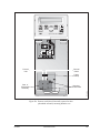
1
Finnigan™ SpectraSYSTEM™ UV/Vis Detectors Reference Manual A0099-540 Revision G Finnigan™ and SpectraSYSTEM™ are trademarks of Thermo Electron Corporation. This manual and the instruments to which it applies have satisfied the requirements for CSA, FCC, the EMC, and Low Voltage Directives. Use of non-approved components and repair methods may reduce or invalidate the built-in protection that is required to meet the above certifications. Technical information contained in this publication is for reference purposes only and is subject to change without notice. Every effort has been made to supply complete and accurate information; however, Thermo Electron Corporation assumes no responsibility and will not be liable for any errors, omissions, damage, or loss that might result from any use of this manual or the information contained therein (even if this information is properly followed and problems still arise). This publication is not part of the Agreement of Sale between Thermo Electron Corporation and the purchaser of an LC system. In the event of any conflict between the provisions of this document and those contained in Thermo Electron Corporation’s Terms and Conditions, the provisions of the Terms and Conditions shall govern. System Configurations and Specifications supersede all previous information and are subject to change without notice. Printing History: Revision G printed in January 2004 The products of Thermo Electron San Jose are produced under ISO 9001 accredited quality management systems. Australia: P.O. Box 239 Rydalmere • Unit 14, 38 – 46 South Street • Rydalmere, N.S.W. 2116 • [61] (02) 9898-9000 Austria: Wehlistrasse 27b • A-1200 Wien • [43] (01) 333 50 34-0 Belgium: Technologiestraat 47 • B-1082 Brussels • [32] (02) 482 30 30 Canada: 5716 Coopers Avenue, Unit 1 • Mississauga, Ontario • L4Z 2E8 • [1] (905) 712-2258 France: 16 Avenue du Québec • Silic 765 • Z.A. de Courtaboeuf • F-91963 Les Ulis Cédex • [33] (01) 60 92 48 00 Germany: Im Steingrund 4-6 • D-63303 Dreieich • [49] (06103) 408 0 Italy: Strada Rivoltana • I-20090 Rodano (Milano) • [39] (02) 95059 226 Japan: C-2F • 3-9, Moriya-cho, Kanagawa-ku • Yokohama, Kanagawa • 221-0022 • [81] (45) 453 9100 Japan: Esaka Grand Building • 2-3-1 Esaka-cho, Suita City • Osaka 564-0063 • [81] (06) 6387-6681 Netherlands: Takkebijsters 1 • NL-4817 BL Breda • [31] (076) 5878 722 P.R. China: Room 901, Ping-an Mansion • No. 23, Jin Rong Street • Xi Cheng District • Beijing 100032 • [86] (010) 6621 0839 Spain: Sepulveda 7 A • ES-28108 Alcobendas (Madrid) • [34] (091) 657 4930 Spain: Acer 30 – 32 • Edificio Sertram – Planta 2, Modulo 3 • ES-08038 Barcelona • [34] (093) 223 0918 Sweden: Pyramidbacken 3 • S-141 75 Kungens Kurva (Stockholm) • [46] (08) 556 468 00 United Kingdom: Stafford House • 1 Boundary Park • Boundary Way • Hemel Hempstead • Hertfordshire HP2 7GE • [44] (01442) 233 555 U.S.A.: 355 River Oaks Parkway • San Jose, CA 95134-1991 • [1] (408) 965-6000 Notes: The country code is enclosed in square brackets [ ]. The city code or area code is enclosed in parenthesis ( ). For countries other than the U.S.A., when you are dialing from within the specified country, dial the 0 of the city code. For countries other than Italy, when you are dialing from outside the country, do not dial the 0 of the city code. Published by Technical Publications, Thermo Electron Corporation, San Jose, California. Copyright© 2004 Thermo Electron Corporation. All rights reserved. Printed in the United States of America. Customer Registration... Register now and receive all the privileges associated with being a Thermo Electron, Finnigan product user, including application reports and technical reports. Name _______________________________________________________________________________________ Title ________________________________________________________________________________________ Company ___________________________________________________________________________________ Address _____________________________________________________________________________________ City/State/Postal Code _________________________________________________________________________ Country _____________________________________________________________________________________ Telephone _____________________________________________Ext. __________________________________ SpectraSYSTEM UV/Vis Detector Serial # _________________Date Purchased ________________________ Tell us more... Let us know more about how you use this product: My Organization Is: (Check one only) Commercial (for profit) lab Government lab Hospital / Clinic Research Institute University / College Veterinary Other ___________________________ Job Function: (Check one only) Administration Lab Management Operator Other ___________________________ My Primary Application Is: (Check one only) Analytical Biomedical Clinical / Toxicology Energy Food / Agriculture Forensic / Toxicology Pharmaceutical Research / Education Other ___________________________ Reader Survey... Help us to improve the quality of our documentation by answering a few questions: Finnigan SpectraSYSTEM UV/Vis Detector Reference Manual The manual is well organized. The manual is clearly written. The manual contains all of the information I need. The instructions are easy to follow. The instructions are complete. The technical information is easy to understand. The figures are helpful. Revision G A0099-540 Strongly Agree Agree Disagree Strongly Disagree 1 1 1 1 1 1 1 2 2 2 2 2 2 2 3 3 3 3 3 3 3 4 4 4 4 4 4 4 Additional Comments: (Attach additional sheets if necessary.) ___________________________________________________________________________________ ___________________________________________________________________________________ ___________________________________________________________________________________ ___________________________________________________________________________________ ___________________________________________________________________________________ ___________________________________________________________________________________ ___________________________________________________________________________________ Tear this sheet from the manual, fold it closed, stamp it, and drop it in the mail. fold From _______________________________ ____________________________________ ____________________________________ Place Stamp Here EDITOR, TECHNICAL PUBLICATIONS THERMO ELECTRON SAN JOSE 355 RIVER OAKS PARKWAY SAN JOSE, CA 95134-1991 UNITED STATES OF AMERICA fold Contents Back Pocket: Quick Reference Card Menu Trees Customer Support ................................................................................................................................ iii Safety Information ............................................................................................................................ vii Start-up Checklist............................................................................................................................. xix List of Spare Parts, Consumables, and Kits.................................................................................... xxi Chapter 1 Getting Started Introduction ............................................................................................................................ Learning Your Way Around ................................................................................................... Instrument Control ................................................................................................................. Manual Conventions ............................................................................................................... What's Next? .......................................................................................................................... 1 1 2 6 8 Chapter 2 A Quick Example Introduction ............................................................................................................................ 9 UV1000, An Example ............................................................................................................ 10 UV2000, An Example .......................................................................................................... 14 What's Next? ........................................................................................................................ 18 Chapter 3 Basic Operations Introduction .......................................................................................................................... Before You Begin ................................................................................................................. UV1000, Single-wavelength Operation ................................................................................. UV2000, Single- and Dual-wavelength Operation ............................................................... More about Files ................................................................................................................... Analog Outputs ..................................................................................................................... 19 19 20 26 32 35 Chapter 4 Advanced Operations Introduction .......................................................................................................................... Wavelength Programming .................................................................................................... Programmed Autozero ......................................................................................................... Automatic Lamp Operations ................................................................................................ Other Features ...................................................................................................................... UV2000, Scanning ................................................................................................................. UV2000, Automatic Scanning ............................................................................................... The Develop File.................................................................................................................... Sample Queue......................................................................................................................... K-Factor ................................................................................................................................. Absorbance Ratios.................................................................................................................. 37 37 40 41 43 46 51 54 56 60 64 01/2004 Thermo Electron i Chapter 5 Required Maintenance Introduction .......................................................................................................................... 67 Flowcells ............................................................................................................................... 67 Lamps ................................................................................................................................... 73 Appendix A Installation and Specifications Introduction .......................................................................................................................... 79 Installation ............................................................................................................................ 79 Specifications ........................................................................................................................ 90 Appendix B Menu Reference Introduction .......................................................................................................................... 93 Menu Trees ........................................................................................................................... 93 Menu Reference .................................................................................................................... 97 Appendix C Troubleshooting Introduction ........................................................................................................................ Theory of Operation ........................................................................................................... Common Problems ............................................................................................................. Troubleshooting Table ........................................................................................................ Error Messages ................................................................................................................... Diagnostic Tests ................................................................................................................. 105 105 107 107 110 112 Appendix D Glossary Introduction ........................................................................................................................ 117 Appendix E Cuvette Holder Accessory Introduction ........................................................................................................................ Installation .......................................................................................................................... Using the Cuvette Holder ................................................................................................... Maintenance ........................................................................................................................ 121 122 127 128 Index ii Thermo Electron 01/2004 Customer Support Thermo Electron San Jose products are supported by Thermo Electron Customer Service Engineers with customer support available in North America, in Europe, and in Australasia and Asia. IN NORTH AMERICA In North America, Thermo Electron Customer Service Engineers are available from each of the Thermo Electron field offices as follows: Northeastern Region Phone [1] (732) 627-0220 Fax [1] (732) 627-0260 Southern Region Phone [1] (770) 516-5589 Fax [1] (770) 516-6916 Central Region Phone [1] (847) 310-0140 Fax [1] (847) 310-0145 Western Region Phone [1] (408) 965-6000 Fax [1] (408) 965-6123 Canada Phone [1] (905) 712-2258 Fax [1] (905) 712-4203 In the Americas, use the following telephone number or fax number to order parts for all instruments: Thermo Electron Customer Service Operations 1400 Northpoint Parkway, Suite 10 West Palm Beach, FL 33407 Phone: [1] (800) 532-4752 Fax: [1] (561) 688-8731 Thermo Electron Technical Support is available at the following location: Thermo Electron Technical Support Operations 1400 Northpoint Parkway, Suite 10 West Palm Beach, FL 33407 Phone: [1] (800) 685-9535 Fax: [1] (561) 688-8736 01/2004 Thermo Electron iii IN EUROPE In Europe, customer support, replaceable parts, and technical support are available from each of the Thermo Electron offices as follows: Wien (Vienna), Austria Phone [43] (01) 333 50 34-0 Fax [43] (01) 333 50 34-26 Brussels, Belgium Phone [32] (02) 482 30 30 Fax [32] (02) 482 30 31 Les Ulis Cédex, France Phone [33] (01) 60 92 48 00 Fax [33] (01) 60 92 49 00 Dreieich, Germany Phone [49] (06103) 408 0 Fax [49] (06103) 408 1222 Milano, Italy Phone [39] (02) 95 059 226 Fax [39] (02) 95 320 370 Breda, Netherlands Phone [31] (076) 587 8722 Fax [31] (076) 571 4171 Madrid, Spain Phone [34] (091) 657 4930 Fax [34] (091) 657 4937 Barcelona, Spain Phone [34] (093) 223 0918 Fax [34] (093) 223 0982 Stockholm, Sweden Phone [46] (08) 556 468 00 Fax [46] (08) 556 468 08 Hemel Hempstead, United Kingdom Phone [44] (01442) 233 555 Fax [44] (01442) 233 667 For all other countries, contact your local Thermo Electron dealer. iv Thermo Electron 01/2004 IN AUSTRALASIA AND ASIA In Australasia and Asia, customer support, replaceable parts, and technical support are available from each of the Thermo Electron offices as follows: Rydalmere, N.S.W., Australia Phone [61] (02) 9898-9000 Fax [61] (02) 9898-9800 Yokohama, Japan Phone [81] (45) 453-9100 Fax [81] (06) 453-9110 Osaka, Japan Phone [81] (06) 6387-6681 Fax [81] (06) 6387-6641 Beijing, P.R. China Phone [86] (010) 6621 0839 Fax [86] (010) 6621 0851 For all other countries, contact your local Thermo Electron dealer. 01/2004 Thermo Electron v Safety and EMC Information In accordance with Thermo Electron’s commitment to customer service and safety, these instruments have satisfied the requirements for the FCC and the European CE Mark including the Low Voltage Directive. Designed, manufactured and tested in an ISO9001 Registered facility, this system has been shipped to you from our manufacturing facility in a safe condition. IDENTIFYING SAFETY INFORMATION This reference manual contains precautionary statements that can prevent personal injury, instrument damage, and loss of data if properly followed. All statements of this nature are called to your attention through the use of bold type and the following icons: CAUTION! HOT SURFACE! HIGH VOLTAGE! Every instrument has specific hazards, so be sure to read and comply with the following precautions. They will help ensure the safe, longterm use of your system. 1. Before plugging in any of the instrument modules or turning on the power, always make sure that the voltage and fuses are set appropriately for your local power supply. 2. Only use fuses of the type and current rating specified. Do not use repaired fuses and do not short-circuit the fuse holder. 3. The supplied power cord must be inserted into a power outlet with a protective earth contact (ground). When using an extension cord, make sure that the cord also has an earth contact. 4. Do not change the external or internal grounding connections. Tampering with or disconnecting these connections could endanger you and/or damage the system. CAUTION! The instrument is properly grounded in accordance with these regulations when shipped. You do not need to make any changes to the electrical connections or to the instrument's chassis to ensure safe operation. CAUTION! Do not override the lamp cover safety interlock, which turns the lamps off when the cover is removed, or personal injury could result. 5. Never run the system without the top cover on. Permanent damage can occur. 01/2004 Thermo Electron vii 6. Do not turn the instrument on if you suspect that it has incurred any kind of electrical damage. Instead, disconnect the power cord and contact a Thermo Electron Service Representative for a product evaluation. Do not attempt to use the instrument until it has been evaluated. (Electrical damage may have occurred if the system shows visible signs of damage, or has been transported under severe stress.) 7. Damage can also result if the instrument is stored for prolonged periods under unfavorable conditions (e.g., subjected to heat, water, etc.). 8. Always disconnect the power cord before attempting any type of maintenance. 9. Capacitors inside the instrument may still be charged even if the instrument is turned off. 10. Never try to repair or replace any component of the system that is not described in this manual without the assistance of Thermo Electron. GOOD LABORATORY PRACTICES Keep Good Records To help identify and isolate problems with either your equipment or your methodology, we recommend that you keep good records of all system conditions (e.g., %RSDs on migration times and peak areas, peak shape and resolution). At a minimum, keep an electropherogram of a typical sample and standard mixture, welldocumented with system conditions, for future reference. Careful comparison of migration times, peak shapes, peak sensitivity, and baseline noise can provide valuable clues to identifying and solving future problems. Chemical Toxicity Although the large volume of toxic and flammable solvents used and stored in laboratories can be quite dangerous, don't ignore the potential hazards posed by your samples. Take special care to read and follow all precautions that ensure proper ventilation, storage, handling, and disposal of both solvents and samples. Become familiar with the toxicity data and potential hazards associated with all chemicals by referring to the manufacturers' Material Safety Data Sheets (MSDS). Sample Preparation Always consider the solubility of your sample in the electrolyte buffer. Sample precipitation can plug the system by obstructing the flow through the capillary. This obstruction may result in irreparable damage to parts of the system. Particulate matter can be avoided by filtering the samples through 0.45- or 0.2-micron (or less) filters. viii Thermo Electron 01/2004 Solvent Requirements Many chemical manufacturers provide a line of high-purity or spectro-quality reagents that are free of chemical impurities. Routine filtration of all solvents or eluents through a 0.45- or 0.2-micron (or less) fluorocarbon filter before placing them in the solvent reservoir will significantly prolong the life and effectiveness of the inlet filters, check valves and seals, injector, and column. Typically, HPLC-grade solvents do not require filtration. Choose a mobile phase that's compatible with the sample and column you've selected for your separation. Remember that some solvents are corrosive to stainless steel. Inert/biocompatible instrument versions are also available from Thermo Electron. Degas the Eluents Degas your eluents using either the vacuum degassing or the helium sparging technique. Complete information for using either of these techniques is found in separate documentation provided with degas accessories. Solvent Disposal Make sure you have a solvent waste container or other kind of drain system available at or below the benchtop level. Most solvents have special disposal requirements and should not be disposed of directly down a drain. Follow all governmental regulations when disposing of any chemical. High-pressure Systems and Leaks LC systems operate at high pressures, but since liquids aren't highly compressible, they do not store much energy. Thus, little immediate danger arises from the high pressure in an LC system. However, if a leak occurs, it should be corrected as soon as possible. Finally, we recommend that you always wear eye and skin protection when working on an LC system and that you always shut down the system and return it to atmospheric pressure before attempting any maintenance. 01/2004 Thermo Electron ix Information sur la sécurité et la compatibilité électromagnétique (CEM) Selon notre engagement à assurer à nos clients service et sécurité, ces instruments sont déclarés conformes aux normes de la FCC et à la réglementation européenne (CE), y compris à la directive sur les basses tensions. Conçu, fabriqué et testé dans une installation homologuée ISO9001, cet instrument a été livré à partir de notre usine de fabrication dans le respect des règles de sécurité. MISE EN GARDE ! Cet instrument doit être utilisé selon les instructions figurant dans ce manuel. Le non respect des consignes d’utilisation de cet instrument décrites dans le présent manuel risque d’endommager l’instrument et/ou d’infliger des blessures à l’opérateur. IDENTIFICATION DES INFORMATIONS SUR LA SÉCURITÉ Ce manuel de référence contient des précautions d’usage afin de prévenir tout dommage corporel ou matériel ainsi que toute perte de données lorsque l’opérateur se conforme aux instructions indiquées. Ces instructions sont accompagnées des icônes suivantes et sont affichées en caractères gras pour attirer l’attention de l’opérateur : MISE EN GARDE ! SURFACE BRÛLANTE ! HAUTE TENSION ! Chaque instrument présentant des dangers spécifiques, il incombe à l’opérateur de lire les précautions suivantes et de s’y conformer, afin de maintenir la durée de vie et la sécurité du système. 1. Avant de brancher un module d’instruments ou de le mettre sous tension, toujours s’assurer que la tension et les fusibles sont réglés de façon à correspondre à la tension locale du secteur. 2. N’utiliser que des fusibles du type et du courant nominal spécifiés. Ne pas utiliser de fusibles réparés et ne pas courtcircuiter le porte-fusible. 01/2004 Thermo Electron xi 3. Le cordon d’alimentation accompagnant l’instrument doit être branché à une prise de courant avec mise à la terre. En cas d’utilisation d’une rallonge électrique, s’assurer que celle-ci comporte également une mise à la terre. 4. Ne pas modifier les connexions de mise à la terre internes ou externes. La modification ou le débranchement de ces connexions représente un danger pour l’opérateur et/ou risque d’endommager le système. MISE EN GARDE ! Cet instrument est mis à la terre conformément aux règlements applicables lors de son expédition. Ne pas modifier les branchements électriques ou le châssis de l’instrument afin d’assurer un fonctionnement en toute sécurité. MISE EN GARDE ! Ne pas abroger le contact de sécurité de couverture de lampe (qui éteignez la lampe quand le couverture est enlevé) ou les blessures pourraient résulter. 5. Ne jamais faire fonctionner le système sans son boîtier. Des dommages permanents pourraient en résulter. 6. Ne pas mettre l’instrument sous tension si celui-ci a subi des dommages électriques. Débrancher le cordon d’alimentation de l’appareil et consulter un représentant du service technique pour procéder à un examen du produit. Ne pas essayer d’utiliser l’instrument avant qu’il n’ait été examiné. (Des dommages électriques peuvent s’être produits si le système montre des signes visibles d’endommagement ou si les conditions de transport ont été extrêmement difficiles.) 7. L’instrument peut également être endommagé s’il est entreposé pendant une période de temps prolongée, dans de mauvaises conditions (par exemple, s’il est exposé à la chaleur, à l’humidité, etc.). 8. Toujours débrancher le cordon d’alimentation avant d’effectuer n’importe quel type d’entretien. 9. Les condensateurs présents à l’intérieur de l’instrument peuvent toujours être chargés, même si l’instrument est hors tension. 10. Ne jamais tenter de réparer ou de remplacer un composant du système non décrit dans ce manuel sans obtenir de l’aide auprès d’un représentant du service technique. BONNES PRATIQUES DE LABORATOIRE Bonne tenue des dossiers Pour permettre d’identifier et d’isoler les problèmes pouvant survenir avec l’équipement ou la méthodologie utilisés, il est recommandé de tenir correctement des dossiers de toutes les conditions du système (p. ex., % CV sur les temps de rétention et les zones de pics, la forme et la résolution des pics). Il est recommandé tout au moins de conserver xii Thermo Electron 01/2004 pour référence future un chromatogramme d’un échantillon type et d’un mélange standard, bien documenté et accompagné des conditions du système. Une comparaison précise des temps de rétention, des formes et de la sensibilité des pics ainsi que des bruits de référence peuvent fournir des indices précieux pour l’identification et la résolution de problèmes futurs. Toxicité chimique Bien que l’utilisation et l’entreposage dans les laboratoires de grandes quantités de solvants inflammables et toxiques puissent représenter un danger, ne pas négliger les dangers potentiels posés par les échantillons. Veiller particulièrement à lire et à suivre toutes les précautions indiquées pour assurer la ventilation, le stockage, la manutention et l’élimination des solvants et des échantillons. Se familiariser avec les données sur la toxicité et les dangers potentiels associés à tous les produits chimiques en consultant les fiches techniques sur la sécurité des substances (FTSS) du fabricant. Préparation des échantillons Toujours considérer la solubilité de l’échantillon dans la phase mobile. La précipitation des échantillons peut boucher la colonne, les tubes et/ou la cellule de dilution, et en limiter le débit. Cette obstruction peut endommager le système de façon irréparable. L’accumulation de particules peut être évitée par la filtration des échantillons à travers des filtres de 0,45 ou 0,2 µm (ou moins). Caractéristiques des solvants Un grand nombre de fabricants de produits chimiques fournissent des réactifs de pureté élevée ou de qualité spectrographique dépourvue de toute impureté chimique. La filtration systématique de tous les solvants ou éluants à travers un filtre fluorocarboné de 0,45 ou 0,2 µm (ou moins) avant de les placer dans le réservoir de solvants prolonge de façon significative la durée de vie et l’efficacité des filtres d’entrée, des clapets et des joints d’étanchéité, de l’injecteur et de la colonne. De façon générale, les solvants pour chromatographie liquide sous haute pression ne nécessitent pas de filtration. Choisir une phase mobile qui est compatible avec l’échantillon et la colonne sélectionnés pour la séparation. Noter que certains solvants sont corrosifs pour l’acier inoxydable. Des versions inertes et biocompatibles des instruments sont disponibles auprès de Thermo Electron. Dégazage des éluants Effectuer le dégazage des éluants selon la méthode de dégazage par le vide ou à l’hélium. Une description complète de ces méthodes est disponible dans la documentation fournie séparément avec les accessoires de dégazage. 01/2004 Thermo Electron xiii Élimination des solvants S’assurer qu’il existe un conteneur pour solvants à éliminer ou tout autre système de vidange au niveau de la table de travail ou audessous de celle-ci. La plupart des solvants doivent être éliminés dans des conditions particulières et ne doivent pas être évacués directement par les canalisations. Respecter la réglementation en vigueur concernant l’évacuation des produits chimiques. Systèmes à haute pression et fuites Les systèmes de chromatographie liquide (CL) fonctionnent à des pressions élevées. Les liquides n’accumulent pas de grandes quantités d’énergie car ils ne sont pas hautement compressibles. Par conséquent, le risque d’un danger immédiat causé par les pressions élevées dans un système CL est faible. En revanche, si une fuite survient, il est nécessaire de la réparer le plus rapidement possible. Enfin, il est recommandé à l’opérateur de se protéger en permanence les yeux et la peau lorsqu’il travaille sur un système CL. De plus, il doit toujours mettre le système hors tension et le ramener à la pression atmosphérique avant de procéder à tout entretien. xiv Thermo Electron 01/2004 Informationen zu Sicherheit und Funkentstörung Wir sind dem Dienst am Kunden und der Sicherheit des Kunden verpflichtet. Diese Geräte entsprechen den Anforderungen für die FCC-Zulassung und für das CE-Zeichen sowie den Bestimmungen der Richtlinie für Niederspannungsgeräte. Dieses Gerät wurde in einer nach ISO 9001 zertifizierten Fertigungsstätte entwickelt, hergestellt und getestet und hat unser Werk in sicherem Zustand verlassen. VORSICHT! Dieses Gerät darf nur nach den Vorschriften dieser Bedienungsanleitung benutzt werden. Wenn dieses Gerät auf andere Weise als hier beschrieben benutzt wird, kann dies zu Schäden am Gerät oder zur Verletzung des Bedieners führen. ERKENNEN VON SICHERHEITSINFORMATIONEN Dieses Handbuch enthält Warnhinweise, deren genaue Befolgung Personenschäden, Schäden am Gerät oder Datenverluste verhindern kann. Auf alle derartigen Warnhinweise wird durch Fettschrift und durch Verwendung der nachfolgenden Symbole gesondert aufmerksam gemacht: VORSICHT! OBERFLÄCHE HEISS! HOCHSPANNUNG Jedes Gerät kann unter bestimmten Umständen gefährlich sein. Lesen Sie daher in jedem Fall die nachstehenden Sicherheitshinweise, und ergreifen Sie die entsprechenden Maßnahmen. Auf dieses Weise sorgen Sie für einen sicheren Betrieb und eine lange Lebensdauer des Geräts. 1. Bevor Sie eines der Gerätemodule einstecken oder das Gerät einschalten, überprüfen Sie in jedem Fall, ob die Nennspannung und die Sicherungen der Netzspannung der örtlichen Stromversorgung entsprechen. 2. Verwenden Sie nur Sicherungen des angegebenen Typs und der angegebenen Amperezahl. Verwenden Sie keine reparierten Sicherungen, und überbrücken Sie die Sicherung nicht. 01/2004 Thermo Electron xv 3. Das mitgelieferte Netzkabel muß in eine Steckdose mit Schutzleiter eingesteckt werden. Wird ein Verlängerungskabel verwendet, muß auch hier der Schutzleiter durchgeführt sein. 4. Verändern Sie nichts an den externen oder internen Schutz- bzw. Erdungskontakten. Wenn Sie sich an diesen zu schaffen machen oder sie unterbrechen, können Sie sich selbst und andere gefährden, oder das Gerät könnte beschädigt werden. VORSICHT! Das Gerät ist bei der Auslieferung vorschriftsmäßig geerdet. Es brauchen keine Veränderungen an der elektrischen Verkabelung oder am Gerätechassis vorgenommen werden, um einen sicheren Betrieb zu gewährleisten. VORSICHT! Setzen Sie niemals den Sicherheitsschalter der Lampenabdeckung ausser Kraft! Der Sicherheitsschalter schaltet die Lampen aus, wenn die Abdeckung entfernt wird. Die Überbrückung des Sicherheitsschalters kann zu Gesundheitsschäden oder Verletzungen führen. 5. Nehmen Sie das Gerät nie mit geöffnetem Gehäuse in Betrieb, da dies zu irreparablen Schäden führen kann. 6. Schalten Sie das Gerät nicht ein, wenn Sie den Verdacht haben, daß an der Elektrik möglicherweise Schäden eingetreten sind. Ziehen Sie in diesem Fall den Netzstecker heraus, und lassen Sie das Gerät von einem Kundendiensttechniker untersuchen. Versuchen Sie bis zu dieser Untersuchung keinesfalls, das Gerät in Betrieb zu nehmen. (Eine Beschädigung der Elektrik kann z.B. eingetreten sein, wenn das Gerät äußere Schäden aufweist oder unter problematischen Umständen transportiert wurde.) 7. Schäden können auch eintreten, wenn das Gerät längere Zeit unter ungünstigen Umständen gelagert wurde (z.B. unter der Einwirkung von Hitze oder Wasser). 8. Ziehen Sie vor allen Wartungsmaßnahmen immer zuerst den Netzstecker aus der Steckdose. 9. Auch wenn das Gerät abgeschaltet ist, können die im Inneren befindlichen Kondensatoren nach wie vor unter Spannung stehen. 10. Versuchen Sie niemals, Gerätekomponenten zu reparieren oder auszutauschen, die nicht in diesem Handbuch beschrieben sind, ohne einen Kundendiensttechniker zu Rate zu ziehen. xvi Thermo Electron 01/2004 GLP-VORSCHRIFTEN (GOOD LABORATORY PRACTICES) Ordnungsgemäße Aufzeichnungen Damit Probleme mit Geräten oder Methoden erkannt und eingegrenzt werden können, empfehlen wir Ihnen, ordnungsgemäße Aufzeichnungen sämtlicher Gerätezustände (z.B. % RSDs zu Retentionszeiten, Kurvenflächen, Kurvenformen und Auflösung). Archivieren Sie als Minimum ein Chromatogramm einer typischen Probe und einer Standardmixtur mit umfassender Dokumentation der Systembedingungen zum späteren Vergleich. Ein sorgfältiger Vergleich von Retentionszeiten, Kurvenformen, Empfindlichkeitswerten und Hintergrundrauschen liefert wertvolle Hinweise für den Fall, daß zu einem späteren Zeitpunkt Probleme auftreten und eingegrenzt und behoben werden müssen. Chemische Toxizität Die großen Mengen an toxischen oder brennbaren Lösungsmitteln, die im Labor verwendet und aufbewahrt werden, können ein erhebliches Gefahrenpotential darstellen, doch darf man hierüber nicht die mögliche Gefährdung durch die Proben selbst vergessen. Achten Sie insbesondere darauf, sämtliche Warnhinweise hinsichtlich ausreichender Belüftung, Lagerung, Handhabung und Entsorgung von Lösungsmitteln ebenso wie von Proben sorgfältig zu lesen und zu befolgen. Machen Sie sich mit den Toxizitätsdaten und den möglichen Gefahren sämtlicher verwendeter Chemikalien anhand der betreffenden Sicherheitsdatenblätter vertraut, die von den Produktherstellern zur Verfügung gestellt werden. Probenvorbereitung Überprüfen Sie stets die Löslichkeit der Probe in der mobilen Phase. Durch das Ausfällen von Feststoffen können die Säule, die Leitungen oder die Durchflußzelle verstopfen und damit den Durchfluß hemmen. Durch eine solche Verstopfung können irreparable Schäden am System entstehen. Die Ablagerung von Partikeln läßt sich durch Filtrieren der Proben durch ein Filter mit einer Porengröße von 0,45 oder 0,2 µm (oder weniger) vermeiden. Anforderungen an das Lösungsmittel Viele chemische Hersteller bieten eine Produktserie hochreiner Reagenzien in spektroskopisch reiner Qualität an, die frei von chemischen Unreinheiten sind. Die routinemäßige Filtrierung aller Lösungs- und Extraktionsmittel durch ein Fluorkohlenwasserstoff-Filter mit einer Porengröße von 0,45 oder 0,2 µm (oder weniger) vor dem Einfüllen in den Lösungsmittelbehälter verlängert die Lebensdauer der Einlaßfilter, der Ventile und Dichtungen, des Injektors und der Säule beträchtlich. Spezielle HPLC-Lösungsmittel brauchen normalerweise nicht filtriert zu werden. 01/2004 Thermo Electron xvii Wählen Sie eine mobile Phase, die zur Probe und zur für die Separation verwendete Säule kompatibel ist. Dabei ist darauf zu achten, daß Edelstahl durch bestimmte Lösungsmittel korrodiert wird. Reaktionsträge, biokompatible Geräteausführungen werden ebenfalls von Thermo Separation Instruments angeboten. Entgasen des Lösungsmittels Lösungs- und Extraktionsmittel sollten entgast werden, und zwar entweder durch Vakuum oder Heliumdurchperlung. Eine umfassende Beschreibung dieser Techniken finden Sie in dem separaten Handbuch, das dem Entgasungszubehör beiliegt. Entsorgung von Lösungsmitteln Sorgen Sie dafür, daß ein Auffangbehälter für Lösungsmittel oder eine andere Auffangvorrichtung in Höhe des Arbeitstisches oder darunter zur Verfügung steht. Für die meisten Lösungsmittel gelten besondere Entsorgungsvorschriften; eine Entsorgung über die Abwasserleitung ist hier nicht zulässig. Bei der Entsorgung von Chemikalien gleich welcher Art sind die einschlägigen Vorschriften streng zu beachten. Hochdrucksysteme und Undichtigkeiten Flüssigchromatographen arbeiten unter hohem Druck. Da Flüssigkeiten kaum komprimierbar sind, können sie nicht viel Energie speichern. Dementsprechend stellt der hohe Druck in einem Flüssigchromatographen auch kaum eine unmittelbare Gefahr dar. Jedoch sollten auftretende Undichtigkeiten umgehend beseitigt werden. Schließlich ist noch zu empfehlen, bei der Arbeit mit einem Flüssigchromatographen stets Augen und Haut zu schützen und vor allen Wartungsarbeiten darauf zu achten, daß das Gerät abgeschaltet und druckfrei gemacht wurde. xviii Thermo Electron 01/2004 Startup Checklist Use this checklist to ensure that you have completed all the steps necessary for the proper installation of your Finnigan™ SpectraSYSTEM™ UV/Vis detector. Complete installation information can be found in Appendix A. UNPACKING ❒ ❒ ❒ Unpack and inspect your instrument. Check for damage. Check your accessory kit and manual. Are they: ❍ present? ❍ complete? Read the Safety Information Card. POSITIONING DETECTOR ❒ Place on benchtop as close as possible to the column and at least 5 inches (13 cm) from the wall. POWER CHECKOUT ❒ ❒ Set voltage for local requirements. Check that the correct fuses are installed. REAR PANEL CONNECTIONS ❒ ❒ ❒ ❒ 01/2004 Insert the 8- and 12-pin green connectors into their corresponding sockets. Connect the Analog Output and the corresponding ground terminals to your data system/recorder. Connect the desired remote communications terminals to external devices: ❍ STOP (Input) ❍ RUN (Input) ❍ ZERO (Input) ❍ READY (Output) Connect the power cord. Thermo Electron xix FLOWCELL CONNECTIONS ❒ ❒ ❒ Remove the detector's front panel. Remove the flowcell assembly from the detector. Connect the flowcell inlet directly to your LC column outlet. ❒ ❒ Connect the flowcell outlet to waste tubing and a waste container. Replace the detector's front panel. INSTRUMENT POWER-UP ❒ ❒ Install the power cord and turn on the instrument. Check that self-tests are running and that no error messages appear. ❒ Check that the Status Screen appears on display. ❒ Complete and return the registration card. REGISTRATION CARD xx Thermo Electron 01/2004 List of Spare Parts, Consumables, and Kits Shown below is a list of spare parts and consumables available from Thermo Electron for use with your Finnigan SpectraSYSTEM UV/Vis detector. Contact your local Thermo Electron representative for current prices. Flowcells 9550-0100 9550-0234 9550-0197 9550-0053 9550-0265 9550-0101 9550-0263 Analytical LC (6 mm) Analytical LC (10 mm) Biocompatible LC (6 mm) Microbore (3 mm) Microbore (6 mm) Semi-preparative, Open Column (3 mm) Cuvette Cell Holder Options And Accessories 2103-9119 A4095-010 9551-0022 9551-0023 9051-0143 External Events Connector Remote Interface Cable Tungsten Lamp, prealigned Deuterium Lamp, prealigned Regulated Backpressure Accessory Manuals A0099-540 UV/Vis Detectors Reference Manual (English) Maintenance Parts A4051-010 A4061-010 Standard Fittings Kit (Kit includes stainless steel fittings and tubing used in a Finnigan SpectraSYSTEM LC system.) Inert/Biocompatible Fittings Kit (Kit includes PEEK fittings and tubing used in an inert/biocompatible Finnigan SpectraSYSTEM LC system.) Upgrade Kits Upgrade kits are available for the Finnigan SpectraSYSTEM UV1000 detector. Contact your local Thermo Electron Representative for details. 01/2004 Thermo Electron xxi 1 Getting Started Introduction This Chapter provides you with the three basic rules you'll need for using your Thermo Electron, Finnigan SpectraSYSTEM UV/Vis detector. It also introduces you to the instrument's command center and describes the conventions we'll use in this manual. Before you start this chapter, be sure to read the Safety Information section beginning on page v of this manual and to install your detector as described in Appendix A. Throughout our explanations, we encourage you to explore the general architecture of the instrument's menus and screens. Use the Menu Tree in Appendix B as your guide if you wish. Learning Your Way Around AS EASY AS 1-2-3! It's easy to learn your way around a SpectraSYSTEM detector. Just remember these three rules: 1. The arrow keys ([∧], [∨], [<], [>]) move the cursor in the direction printed on the key. HINT: Press [MENU] to jump quickly to the top of the menu structure. 2. The shape of the cursor determines how you make a selection: • If a triangular Cursor appears, press [ENTER]. • If a blinking square cursor ( ) appears, press the [+] or [-] keys to change values. Depending on the field, you will scroll up or down through preset choices, or change alphanumeric entries one letter or digit at a time. 3. There are four ways to accept (and automatically save) an entry. Just move the cursor out of the field by any of the following methods: • Pressing [ENTER] • Using the arrow keys • Pressing [MENU] • Pressing [STATUS] NOTE: You won't be able to leave a menu if errors are present or if you haven't filled in all the necessary entries. 01/2004 Thermo Electron 1 VISUAL CLUES The following conventions are used on the detector's display: 1. Top-level menu choices are displayed in all-capital letters. 2. A field's square cursor changes to an underscore cursor when you're scrolling through preset choices or entering numerical values and characters. 3. A solid down-arrow (T) on the right side of some displays indicates that the current menu continues on additional screens. To access additional menu lines, press the down-arrow key, [∨]. 4. The last line of a longer menu is frequently a blank display line (without a solid down-arrow). Instrument Control Take a look at the keypad and two-line display located on the front panel (Fig. 1.1). This is the command center from which you'll access menus and control the instrument's operations. A brief explanation of the keys and the main menus and screens follows. RUN STATUS MENU STOP SpectraSYSTEM UV2000 ZERO DET\Z008\FM ENTER Figure 1.1 The detector's command center 2 Thermo Electron 01/2004 THE KEYPAD The keypad of each SpectraSYSTEM instrument consists of twelve keys. Four keys directly control the instrument's operation: [RUN], [STOP], [STATUS], and, on the detector, a blank key called [ZERO]. The remaining keys either access commands ([MENU] and [ENTER]), or are used to set parameters and move around the display ([∧], [∨], [<], [>], [+], [-]). The function of each is explained below. [RUN] Pressing [RUN] starts a run. The detector must be in the READY state (or QREADY if a queue is loaded), indicating that the detector is stabilized and waiting to begin a run. [STOP] Pressing [STOP] halts a run, stops the internal clock, and returns the detector to a READY state. If a wavelength program is operating, pressing [STOP] halts the program and returns the detector to its initial conditions. [STATUS] Pressing [STATUS] displays the Status Screen (Fig. 1.1). From the Status Screen you can monitor the run in progress. You can also access the Status Menu. See page 5 for more information. [ZERO] The unlabeled key is the only variable key in the whole SpectraSYSTEM family. On the detector, the blank key is the [ZERO] key. The key's name appears on the nameplate below the key. Pressing [ZERO] resets the detector output to zero volts, plus or minus any offset. [MENU] Pressing [MENU] displays the Main Menu (Figs. 1.2 and 1.1). See page 4 for more information. [ENTER] Pressing [ENTER] accepts a selected choice or menu entry. The [ENTER] key also advances the cursor to a new field, either on the same line of the display or in the line below. 01/2004 Thermo Electron 3 [∧], [∨], [<], and [>] Pressing any arrow key (up, down, left, or right) moves the cursor in the direction indicated on the key. The up- and down-arrow keys also move the cursor between menus and displays. [+] and [-] Pressing the [+] and [-] keys scrolls you through a field's available choices or changes the value of alphanumeric entries. Holding down either key will continuously scroll the list of choices forward or backward until you release the key. In fields that require numerical entries, the value of each digit is increased or decreased by one unit each time you press the [+] or [-] key. In fields that accept either numeric or character entries, such as the File Name field, the [+] and [-] keys scroll through the alphabet from A to Z, then through the numbers 0 to 9, and finally to a slash, hyphen, and blank space. In other fields, the [+] key advances you through a preset list of choices while the [-] key takes you back through the list. MENUS, SCREENS, AND MESSAGES Your detector's display can show you three kinds of information: menus, screens, and messages. Menus require you to make selections or enter specific values. Screens display information that cannot be edited. Messages confirm actions and point out errors. The Menu Tree in Appendix B outlines the structure and content of the detectors' menus and screens. Main Menu The Main Menu is the top level of the menu structure. In the UV1000, (Fig 1.2) the Main Menu gives you access to four other menus: FILE, COMMANDS, OPTIONS, and TESTS. In the UV2000, there is and additional menu choice, QUEUE (Fig. 1.3). To see the Main Menu, press the [MENU] key at any time. > ❑ COMMANDS FILES ❑ OPTIONS ❑ TESTS Figure 1.2 The UV1000's Main Menu > ❑ QUEUE FILES ❑ COMMANDS ❑ TESTS ❑ OPTIONS Figure 1.3 The UV2000's Main Menu 4 Thermo Electron 01/2004 From the UV1000’s and the UV2000's File(s) Menu you can edit, load, delete or copy files. The UV2000 also lets you copy files. The Commands Menu lets you insert an event mark onto your chromatogram, short outputs, or shut down the detector. The Tests Menu lets you run built-in instrument tests and diagnostics. In the Options Menu, you can set up or change your instrument's configuration. From the Queue Menu you can edit or change the order of files in the sample queue. Refer to Chapters 3, 4, 5, and Appendix B for more information on any of the instrument's menus. Status Screen The Status Screen (Fig. 1.4) displays the detector status, wavelength setting(s), and the absorbance reading. It automatically appears whenever the instrument is powered on or the [STATUS] key is pressed. No entries are made on the Status Screen. Status λ AU READY 250 0.00001 T Figure 1.4 The Status Screen Status Menu Just below the Status Screen is the Status Menu. To access the Status Menu, press the down-arrow key from the Status Screen. The Status Menu lets you review and edit run parameters during a run. Chapter 3 discusses the Status Menu in more detail. MESSAGES There are three different kinds of messages that can appear on your detector's display: user messages, confirmation messages, and error messages. User Messages User messages, indicated on the display by double asterisks, tell you about an existing instrument condition or ask for further actions. Some of these will only appear on the display for three seconds. An example of a message requiring further action is shown in Figure 1.5. ** Protected File ** No Editing Allowed Figure 1.5 An example of a user message 01/2004 Thermo Electron 5 Confirmation Messages Confirmation messages (Fig. 1.6), also indicated on the display by asterisks, appear for one second after an operation has been carried out successfully. ** File Loaded ** Figure 1.6 An example of a confirmation message Error Messages Error messages (Fig. 1.7), indicated on the display with capital letters and exclamation points, are shown whenever an undesirable condition exists that prevents the instrument from carrying out an operation. Error messages remain on the display until you press a key. !! RAM ERROR !! Figure 1.7 An example of an error message Manual Conventions This manual uses several conventions. Among them are menu displays, text conventions (brackets, slashes, etc.), standard words, and several different icons. DISPLAYS Figure 1.8 shows how we depict the two-line display. Note that, in menu illustrations, the triangular cursor location is indicated by a caret (>). > ❑ COMMANDS FILE ❑ OPTIONS ❑ TESTS Figure 1.8 A two-line menu display Frequently the two lines shown on the display are only part of a longer menu. In this manual, menus having more than two lines are represented as in Figure 1.9. 6 Thermo Electron 01/2004 Zero on λ Change Yes Cursor Speed Medium --------------------------------------------------------Status Lock Off READY Output Active Hi Figure 1.9 A menu longer than two lines TEXT Three typographic conventions are used to differentiate between keys, menus, and fields. Brackets Brackets, [ ], indicate instrument keys. For example: Press [MENU]. Slashes Slashes, / /, are used around menu choices. For example: From the Main Menu, select /FILES/. Capitalization Capitalization is used to make field and menu names appear just as they do on the display. Generally, the first letters of field names are capitalized. For example: Select /FILES/, /Copy/, Copy File #. STANDARD WORDS We have also standardized the meanings of two words: "select" and "enter." select The word "select" is used when you need to choose from among available options. For example, to "select" a particular menu choice, you would move the cursor to the appropriate choice and press [ENTER]. To "select" a field entry, move the cursor to the appropriate field and use the [+] and [-] keys to scroll to the desired preset value. enter The word "enter" is used when you need to specify individual alphanumeric digits. To "enter" a particular value, move the cursor to the desired field and use the [+] and [-] keys to increment or decrement each digit in the field until the desired value or letter appears. 01/2004 Thermo Electron 7 ICONS This manual uses the following icons to alert you to various situations. Each is called out by an icon in the left margin. Caution! A caution alerts you to situations that could result in personal injury. It also tells you how to avoid them. High Voltage! This icon alerts you to the presence of high voltage and to the potential injury that could occur from electrical shock were you to come in contact with a specific instrument area or component. It also tells you how to avoid contact with the high-voltage areas in your instrument. Hot Surface! This icon alerts you to potential injury that could occur from coming in contact with a heated surface or area on or in an instrument. It also tells you how to avoid contact with the heated surfaces in your instrument. Note Notes alert you to the correct operating or maintenance procedures needed to prevent equipment or data damage. They also alert you to important exceptions, side effects, or unexpected occurrences that may result from certain action(s). Hint Hints call out general rules or shortcuts. They specify ways to obtain the best performance and results from your instrument. What's Next? Now you're ready to try the practice example in Chapter 2: A Quick Example. 8 Thermo Electron 01/2004 2 A Quick Example Introduction In Chapter 1, you read about the three easy rules for using your detector's command center and some of its menus and screens. In this chapter, you will find an example procedure that shows you how the rules and keys actually work as you move through the various menus. Instructions begin on page 10 for the UV1000 and on page 14 for the UV2000. This quick example uses only a fraction of the features available on your detector and is included only as a first step in becoming familiar with your new instrument. After experimenting with this example, you'll want to turn to Chapters 3 and 4, which cover the detector's basic and more advanced operations. It is in those chapters that you'll learn about the full capabilities of your detector. First though, to give you a general understanding of the detectors' capabilities and design, we will briefly describe the features and benefits of the UV1000 and UV2000 here. THE UV1000 The UV1000 detector is a time-programmable, variable-wavelength UV/Vis (ultraviolet/visible) absorbance detector. It operates in single-wavelength mode in either the UV range (using a deuterium lamp), or in the visible range (with an optional tungsten lamp). The UV1000’s optical system has a novel, high light-throughput design that provides high sensitivity detection along with maximal application versatility. The UV1000 detector can be upgraded to a UV2000. THE UV2000 The UV2000 detector is a full-featured, time-programmable, dualwavelength UV/Vis absorbance detector. It operates in both singleand dual-wavelength modes in the UV and visible ranges. The UV2000 offers the same optical system design as the UV1000. In addition to the features of the UV1000, the UV2000 also offers spectral scanning, a Develop File (for method development), multiple file storage, a Queue feature (that allows you to link files), and more. BEFORE YOU BEGIN Once the detector is installed in your chromatographic system according to the procedures described in Appendix A and you have completed the Startup Checklist, you are ready to begin your quick example. 01/2004 Thermo Electron 9 UV1000 An Example In this example, we will show you how to prepare an edit file and how to load the edit file into the detector's run file. After a practice run, we will add a stop-time. HINT: You may wish to keep the Menu Tree in Appendix B on hand as you work through this example. If you lose your place at any time, you can: 1. 2. STARTUP Press the [∧] key to move back to a previous screen. Or, press [STATUS] to return to the Status Screen and retrace your steps. Set the power switch located on the detector's rear panel to On. After a series of power-up tests, the Status Screen (Fig. 2.1) appears on the display. (We will discuss the Status Screen after you have set up your operating parameters.) Status λ AU READY 250 0.00001 T Figure 2.1 The UV1000's Status Screen SETTING PARAMETERS To set your parameters, you need to prepare an edit file. The following steps will show you how to access the Edit Menu and prepare the file: 1. Press the [MENU] key. The detector's Main Menu appears on the screen (Fig. 2.2). > ❑ COMMANDS FILE ❑ OPTIONS ❑ TESTS Figure 2.2 The UV1000's Main Menu 2. Now select /FILES/ to display the Files Menu (Fig. 2.3). > ❑ Load Edit ❑ Delete Figure 2.3 The UV1000's Files Menu 10 Thermo Electron 01/2004 3. Select /Edit/ to display the Edit Menu (Fig. 2.4). > Wavelength Program ❑ Options Figure 2.4 The UV1000's Edit Menu Wavelength You use the Wavelength program to set the monitoring wavelength. Wavelength is an example of a field that requires a numeric entry. To set the wavelength: 1. From the Edit Menu (Fig. 2.4), select /Wavelength Program/ to display the Wavelength Program (Fig. 2.5). Time 0.00 Wavelength 254 Figure 2.5 The UV1000's wavelength program 2. Using the [+] and [-] keys, edit the wavelength field to the desired setting for your analysis. Remember that each digit must be edited individually. 3. Press [ENTER] to accept the new wavelength setting. Range Range is an example of a field that has a preset list of choices. To set the range: 1. Select /Options/ from the Edit Menu (Fig. 2.4) to display the Options Menu (Fig. 2.6). Rise Time 1.0 Autozero Time 0.00 --------------------------------------------------------Range 1.0 Figure 2.6 The UV1000's Options Menu 2. Scroll down in the Options Menu and move the cursor to Range 1 using the [∨] key. 3. Using the [+] or [-] key, select the desired setting from the list of choices. 4. Press [ENTER] to accept the new range setting. We will use the rise time and autozero time default settings for this example. You will learn more about setting these parameters in Chapter 3. 01/2004 Thermo Electron 11 Loading the File You are now ready to load the settings from the edit file into the detector's operating parameters (its run file). To load the file: 1. Return to the File Menu (Fig. 2.3) using the [∧] key. 2. Select /Load/. The screen in Figure 2.7 appears. >Load File Figure 2.7 The Load File command 3. Press [ENTER] to execute. The confirmation message shown in Figure 2.8 appears for one second. ** File Loaded ** Figure 2.8 The file-loaded message You are automatically returned to the Status Screen and are ready to run your detector. A PRACTICE RUN Now you're ready for a practice run! Note that the Status Screen (Fig. 2.1) now displays your wavelength setting, the detector's status, and the absorbance reading. If the Status reads READY, the required lamp is lit; if it reads NRDY (Not Ready), there is an error or the lamp isn't lit; and if it reads UVW, the ultraviolet (D2) lamp is still warming up. When the baseline is stabilized: 1. Press the [ZERO] key to zero the detector's analog output signal. 2. Inject your sample. During setup, you may have noticed that there was no stop-time entered in the detector's parameters. In this case, the detector stays in the READY state and continually monitors the column eluant. You do not need to manually start or stop a run with this set-up. 12 Thermo Electron 01/2004 ADDING A STOP-TIME To add a stop-time, you need to modify the detector's operating parameters as follows. We will then show you how to start and stop a run using the new setting. 1. From the Status Screen, press the [∨] key to move down to the Status Menu (Fig. 2.9), which is the programming area below the Status Screen. The cursor appears on the “tens” digit of the wavelength value. Time Wavelength 0.00 250T ----------------------------------------------------------Rise Time 1.0 Autozero Time 0.00 Range 1.0 Figure 2.9 The UV1000's Status Menu 2. Using the [∨] key, move the cursor to the blank line below the 0.00 time line and press [+]. This adds a second line, with a time of 1.00 and the same wavelength setting as the first. Change 1.00 to the desired stop-time for the run, and leave the wavelength unchanged. 3. To save your edits, scroll down to the words "Save File" which now appear below Range, and press [ENTER]. The confirmation message shown in Figure 2.10 appears and you are automatically returned to the Status Screen. ** File Saved ** Figure 2.10 The file-saved message RUNNING WITH A STOP-TIME Now that you have entered a stop-time, you will need to start the run with each injection. 1. Zero the detector's analog output signal by pressing the [ZERO] key. 2. When the detector is stabilized, inject your sample and press [RUN]. Notice that Status now shows the run time. If you wish to stop your run before the set stop-time, simply press [STOP]. 01/2004 Thermo Electron 13 UV2000 An Example In this example, specifically designed for the UV2000, we will show you how to prepare a file and how to load it into the detector's operating parameters. After a practice run, we will add a stop-time. To keep the instructions simple, we will use the single-wavelength mode. HINT: You may wish to keep the Menu Tree in Appendix B on hand as you work through this example. If you lose your place at any time, you can: 1. 2. STARTUP Press the [∧] key to move back to a previous screen. Or, press [STATUS] to return to the Status Screen and retrace your steps. Set the power switch located on the detector's rear panel to On. After a series of power-up tests, the Status Screen (Fig. 2.11) appears on the display. (We will discuss the Status Screen after you have set up your operating parameters.) Status λ AU READY 250 0.00001 T Figure 2.11 The UV2000's Status Screen SETTING PARAMETERS To set your parameters, you need to prepare an edit file. The following steps will show you how to access the Edit Menu and prepare the file: 1. Press the [MENU] key. The detector's Main Menu appears on the screen (Fig. 2.12). > ❑ QUEUE FILES ❑ COMMANDS ❑ TESTS ❑ OPTIONS Figure 2.12 The UV2000's Main Menu 2. Now select /FILES/ to display the Files Menu (Fig. 2.13). > Edit ❑ Load ❑ Copy ❑ Delete Figure 2.13 The UV2000's Files Menu 14 Thermo Electron 01/2004 3. Select /Edit/ to display the Edit Menu (Fig. 2.14). Edit File 1 File Name --------------------------------------------------------> Wavelength Program ❑ Options Figure 2.14 The UV2000's Edit Menu For this example, we will use a file designation of 1 and leave the File Name field blank. Wavelength Wavelength is an example of a field that requires a numeric entry. To set the wavelength: 1. From the Edit Menu (Fig. 2.14), select /Wavelength Program/ to display the Wavelength Program (Fig. 2.15). Program Single λ --------------------------------------------------------Time Wavelength 0.00 254 Figure 2.15 The UV2000's wavelength program 2. Scroll down to the wavelength field. 3. Using the [+] and [-] keys, edit the wavelength field to the desired setting for your analysis. Remember that each digit must be edited individually. 4. Press [ENTER] to accept the new wavelength setting. Range Range is an example of a field that gives you a preset list of choices. Note that Range 1 and 2 correspond to Analog Outputs 1 and 2 on the rear panel of your detector. To set the range: 1. Select /Options/ from the Edit Menu (Fig. 2.14) to display the Options Menu (Fig. 2.16). Rise Time 1.0 Autozero Time 0.00 --------------------------------------------------------Range 1 1.0 Range 2 1.0 Figure 2.16 The UV2000's Options Menu 01/2004 Thermo Electron 15 2. Scroll down in the Options Menu and move the cursor to Range 1 using the [∨] key. 3. Using the [+] or [-] key, select the desired setting from the list of choices. 4. Press [ENTER] to accept the new Range 1 setting. We will use the rise time, autozero time, and range 2 default settings for this example. You will learn more about setting these parameters in Chapter 3. Loading the File You are now ready to load the settings from File 1 into the detector's operating parameters. To load the file: 1. Return to the Files Menu (Fig. 2.13) by pressing either [ENTER] or the [∨] key. 2. Select /Load/. The screen in Figure 2.17 appears. > Load File 1:(filename) Figure 2.17 The Load File command 3. You will be able to select from among several files in the Load File field. Depending on whether or not your detector has ever been used before, these files will either contain previously stored settings or default settings. Use the [+] and [-] keys to scroll through available choices. When the file you wish to load appears (we're using the default settings for this example), press [ENTER] to execute the load command. 4. The confirmation message shown in Figure 2.18 appears for one second, after which you are automatically returned to the Status Screen. ** File Loaded ** Figure 2.18 The file-loaded message A PRACTICE RUN 16 Now you're ready for a practice run! Note that the Status Screen (Fig. 2.11) now displays your wavelength setting, the detector's status, and the absorbance reading. If the Status reads READY, the required lamp is lit; if it reads NRDY (Not Ready), there is an error (for example, you may have chosen a wavelength outside the selected lamp's range) or the lamp isn't lit; and if it reads UVW, the ultraviolet (D2) lamp is still warming up. Thermo Electron 01/2004 When the detector is stabilized: 1. Press the [ZERO] key to zero the detector's analog output signal. 2. Inject your sample. During setup, you may have noticed that there was no stop-time entered in the detector's parameters. In this case, the detector stays in the READY state and continually monitors the column eluant. You do not need to manually start or stop a run with this set-up. ADDING A STOP-TIME To add a stop-time, you need to modify the detector's operating parameters as follows. We will then show you how to start and stop a run using the new setting. 1. From the Status Screen, press the [∨] key to move down to the Status Menu (Fig. 2.19), which is the programming area below the Status Screen. File 1: --------------------------------------------------------Time Wavelength 0.00 250 T Rise Time Autozero Time Range 1 Range 2 1.0 0.00 1.0 1.0 Figure 2.19 The UV2000's Status Menu 2. Using the [∨] key, move the cursor to the blank line below the 0.00 time line and press [+]. This adds a second line, with a time of 1.00 and the same wavelength setting as the first. Change 1.00 to the desired stop-time for the run, and leave the wavelength unchanged. 3. To save your edits, scroll down to the words "Save File" which now appear below Range 2, and press [ENTER]. The confirmation message shown in Figure 2.20 appears and you are automatically returned to the Status Screen. ** File Saved ** Figure 2.20 The file-saved message 01/2004 Thermo Electron 17 RUNNING WITH A STOP-TIME Now that you have entered a stop-time, you will need to start the run with each injection. 1. Zero the detector's analog output signal by pressing the [ZERO] key. 2. When the detector is stabilized, inject your sample and press [RUN]. Notice that Status now shows the run time. If you wish to stop your run before the set stop-time, simply press [STOP]. What's Next? Once you have completed this example and are comfortable with the keypad and display, proceed to Chapter 3, Basic Operations, to learn more about your detector. 18 Thermo Electron 01/2004 3 Basic Operations Introduction This Chapter provides step-by-step instructions for the most frequently used detector operations, including setup and run procedures for single- and dual-wavelength modes, detector file management and protection, and analog output operations. To keep the instructions easy to follow, we have divided the Chapter into two sections. Instructions for the UV1000 begin on page 20. Instructions for the UV2000 begin on page 26. You may wish to keep the Menu Tree and the Menu Reference from Appendix B on hand as you work through this chapter. NOTE: You should be aware that your display's values may differ from those presented in this manual, especially if the detector has been previously programmed. Before You Begin Before you begin this chapter, your detector should be installed in a chromatographic system (see Appendix A), and you should have completed the Startup Checklist located at the front of this manual. We also recommend that you review Chapter 1, Getting Started, which includes general instructions for using the detector keypad and which lists the conventions used throughout this manual. 01/2004 Thermo Electron 19 UV1000 Single-wavelength Operation The UV1000 uses a standard deuterium lamp to operate in a singlewavelength mode in the ultraviolet (UV) range. Adding an optional tungsten lamp increases the detector’s capabilities to the visible (Vis) range. To perform a single-wavelength operation, you first enter the desired detector parameters into an edit file. You then load the edit file into the run file, which contains the detector's current operating parameters. These instructions will show you how to start and stop a run, and how to modify the detector's operating parameters. SETTING PARAMETERS You set up the UV1000’s parameters by using the File Menu to prepare an edit file. You then load the edit file into the run file. To access the File Menu, first press [MENU]. The Main Menu appears on the screen. From the Main Menu, select /FILE/. The menu shown in Figure 3.1 will appear. > ❑ Load Edit ❑ Delete Figure 3.1 The UV1000's Files Menu From the File Menu, select /Edit/ to display the Edit Menu. The Edit Menu (Fig. 3.2) selections are /Wavelength Program/, which contains time and wavelength fields, and /Options/, which contains the Rise Time, Autozero Time, and Range fields. ❑ Wavelength Program ❑ Options Figure 3.2 The UV1000's Edit Menu 20 Thermo Electron 01/2004 Wavelength Program Select /Wavelength Program/ from the Edit Menu. The Wavelength Program is a Table containing the Time and Wavelength fields (Fig. 3.3). Time 0.00 Wavelength 254 Figure 3.3 The UV1000's Wavelength Program In the single-wavelength mode, you can operate with either a one-line or a two-line wavelength program. Using a one-line program, the detector is always in the READY state and you can continually monitor the baseline. Using a two-line program, you can use a stopline and you can start and stop the detector during a chromatographic run. (Stop-lines are useful, for example, in an automated series of runs where you want to autozero the detector's baseline after each injection.) For a one-line program, enter the wavelength(s) for your analysis in the Wavelength field that corresponds to the time of 0.00. For a two-line program, add an additional line (the stop-line) by scrolling down to the blank line below the time 0.00 line and pressing [+]. The second line will automatically have a time setting of 1.00 and the same wavelength setting(s) as the first. Change 1.00 to the desired stop-time for the run, and leave the wavelength value unchanged. An example of a two-line wavelength program for a nine-minute run at 283 nm is shown in Figure 3.4. Time Wavelength 0.00 283 --------------------------------------------------------9.00 283 Figure 3.4 An example of a two-line wavelength program with a programmed stop-time 01/2004 Thermo Electron 21 Options Menu Select /Options/ from the Edit Menu to display the Options Menu (Fig. 3.5). Use this menu to set the detector's rise time, autozero time, and range. Rise Time 1.0 Autozero Time 0.00 ------------------------------------------------------Range 1.0 Figure 3.5 The UV1000's Options Menu Rise Time This field controls the detector's response time. Rise time is inversely proportional to the amount of baseline noise. For example, the longer the rise time, the less noise detected. The one-second default value is appropriate for most applications. HINT: To minimize baseline noise while retaining maximum resolution, select a rise time that is at least one-tenth of the peak width at the base of the narrowest peak of interest. Autozero Time This parameter tells the detector when to perform an automatic zero of the baseline. If you do not wish to set an autozero and you are using a stop-line in your wavelength program, simply set the autozero time to a value greater than your stop-time. HINT: It is good practice to zero the detector automatically at the start of each run. This will keep the detector output in range throughout an automated series of runs. Range This parameter ranges the signal from the Ranged Output. (labeled as “Ranged Output” on the detector's rear panel). Set the range to an appropriate full-scale absorbance for your sample. For more information on the use of ranges and analog outputs, see pages 25 and 84. HINT: We recommend a range of 1.0 when you are using an integrator or data system. Loading the Edit File When you are ready to load the settings from the edit file into the detector’s run file, select /Load/ from the File Menu. The screen will display the words "Load File." Press [ENTER] to accept the settings. The confirmation message shown in Figure 3.6 will appear for one second. You are then returned to the Status Screen. ** File Loaded ** Figure 3.6 The file-loaded message 22 Thermo Electron 01/2004 RUNNING YOUR DETECTOR Once you've set your detector parameters in the edit file and have loaded the parameters into the run file, you’re ready to run your analysis. First, check the detector's status by viewing the Status Screen. If you’re using a stop-line in your wavelength program, you will start and stop the run with each injection. Status Screen You can check the detector's status, wavelength setting, and absorbance reading from the Status Screen (Fig. 3.7). To access the Status Screen, press [STATUS]. Status λ READY 254 AU +0.00001 T Figure 3.7 The UV1000's Status Screen If the Status reads READY, the detector is stabilized and ready to run. If NRDY appears, the detector's lamps may need additional time to warm up, or a wavelength outside the selected lamp's range may have been chosen. Inject your Sample When the detector is stabilized and you are ready to inject your sample, first manually zero the detector by pressing the [ZERO] key. If you are not using a stop-line in the wavelength program, the detector remains in the READY state throughout your chromatographic runs. If you are using a stop-line, you must start and stop the run with each injection, following the procedures below. Starting a Run If you are using a stop-line in your wavelength program, you need to start the run with each injection. There are two ways to start a run using the UV1000: 1. Manually, by pressing [RUN] each time you make an injection. 2. Automatically, by interfacing the detector with a remote runsignal from the injector (see Appendix A for details). In this scenario, a signal that is equivalent to pressing [RUN] is automatically sent from the injector to the detector with each injection. During the run, you can monitor the run time from the Status Screen. Stopping a Run There are two ways to stop a run: 1. Manually, by pressing [STOP] before the programmed stoptime. 2. Automatically, by allowing the run to finish at the programmed stop-time. In either case, the detector returns to its READY state. 01/2004 Thermo Electron 23 CHANGING RUN PARAMETERS There are two ways to change the detector's run parameters: 1. You can use the Files Menu and follow the procedures outlined under "Setting Parameters" on page 20. 2. Or you can use the Status Menu, which is the programming area below the Status Screen. Each method has a distinct advantage. Programming in the Status Menu allows you to change the detector's current operating parameters, even while the detector is running. Programming in the Files Menu allows you to prepare an edit file containing the changes without altering the current detector settings. The file may then be loaded later. Status Menu From the Status Screen, scroll down to the Status Menu (Fig. 3.8). The Status Menu contains the Wavelength Program, Rise Time, Autozero Time, and Range. Time 0.00 Wavelength 254 T --------------------------------------------------------Rise Time 1.0 Autozero Time 0.00 Range 1.0 Figure 3.8 The UV1000's Status Menu The parameters are set using the same instructions given under “Wavelength Program” and “Options Menu,” starting on page 21. When you use the Status Menu to change the UV1000 settings, each change is effective immediately upon leaving the field. Notice the words “Save File” below the Range field. Press [ENTER] when the cursor is in the Save File field to save the new settings to the run file. The confirmation message shown in Figure 3.9 will appear briefly. ** File Saved ** Figure 3.9 The File Saved message NOTE: When you change the detector settings from the Status Menu, the contents of the edit file do not change. Only the run file values are modified. 24 Thermo Electron 01/2004 To return to your previous setting without saving the new ones, do not press [ENTER]. Instead, you may reenter the unaltered file, as follows:: 1. Press [MENU]. 2. Select /FILE/. 3. Select /Load/. 4. The words "Load File" will appear on the screen. Press [ENTER]. A confirmation message (Fig 3.6) will appear for one second. You are then returned to the Status Screen, and all settings will contain their original values. DELETING THE FILE To delete the edit file, select /Delete/ in the File Menu. The words “Delete File” will appear on the screen. When you press [ENTER], the confirmation message shown in Figure 3.10 appears briefly, and the display returns to the File Menu. The edit file parameters return to their default settings. ** File Deleted ** Figure 3.10 The File- Deleted message Analog Outputs There are two analog outputs for the UV1000: Analog Output 1and Analog Output 2. On the detector’s rear panel, they appear as “Unranged output” and “Ranged Output.” Analog Output 1 is set at 1 V/AU and is intended for an integrator interface. Analog Output 2 is range-selectable and is used for recorders and other devices. Rearpanel connections for both outputs are discussed on page 84. ANALOG OFFSETS Analog offsets may be used when there is a high background absorbance reading, or when there is considerable baseline drift from your chromatographic system and you are unable to keep your integrator’s (recorder’s) signal on-scale. Because integrators have very limited capacity for handling negative signals, you may wish to set a small positive offset (1%) when using an integrator. Use negative offsets with recorders, where you may wish to set the pen at either side of the strip chart. 01/2004 Thermo Electron 25 Offset options are selectable from the Analog Outputs Menu. To access these options: 1. Press [MENU]. 2. Select /OPTIONS/ 3. Select /Analog Outputs/. The Analog Outputs Menu is shown in Figure 3.11. Analog 1 Offset (mV) Analog 1 Offset (%) 0 0 Figure 3.11 The UV1000's Analog Outputs Menu HINT: Although the default for the Analog 1 offset is set at zero, we recommend a 1 mV setting for use with your data system or integrator. UV2000 Single- and Dual-wavelength Operation You can operate the UV2000 in either a single- or a dual-wavelength mode. In the dual-wavelength mode, the detector simultaneously monitors two wavelengths in either the UV range or the visible range in a single run. To perform a single- or dual-wavelength operation, you need to be able to identify and enter a file, load that file into the detector's current operating parameters, and start and stop a run. This section will also show you how to modify the detector's current operating parameters. SETTING PARAMETERS Before you set any detector parameters, you need to access the Files Menu to identify the file you wish to edit. To access the Files Menu, first press [MENU]. The Main Menu appears on the screen. From the Main Menu, select /FILES/. The menu shown in Figure 3.12 will appear. >Edit ❑ Load ❑ Copy ❑ Delete Figure 3.12 The UV2000's Files Menu 26 Thermo Electron 01/2004 Select /Edit/ from the Files Menu to display the Edit Menu (Fig. 3.13). Edit File 1 File Name --------------------------------------------------------❑ Wavelength Program ❑ Options Figure 3.13 The UV2000's Edit Menu File Identification Enter the number of the file you wish to edit in the Edit File field. The UV2000 can store up to four files in memory, so file numbers from 1 to 4 are allowed. You may also enter a name of up to eight characters in the File Name field. While in the Edit File, you will see file choices of "S" and "D" that represent the Scan and Develop files, respectively. These files are some of the UV2000's advanced features that you will learn about in Chapter 4. Wavelength Program From the Edit Menu, select /Wavelength Program/. The Wavelength Program designates dual- or single-wavelength operation, and also contains a Table of time and wavelength. A wavelength program for dual-wavelength operation appears in Figure 3.14. Program Dual λ(190-450) --------------------------------------------------------Time λ1 λ2 0.00 254 280 Figure 3.14 The UV2000's Wavelength Program in dual-wavelength mode Select Single λ, Dual λ(190-450), or Dual λ(366-700) in the Program field. The Table for time and wavelength(s) will appear. (For singlewavelength operation, there is only one wavelength field.) You can operate with either a one-line or a two-line wavelength program. Using a one-line program, the detector is always in the READY state and you can continually monitor the chromatographic eluant. Using a two-line program, you can use a stop-line and you can start and stop the detector during a chromatographic run. (Stoplines are useful, for example, in an automated series of runs where you want to autozero the detector's baseline after each injection.) 01/2004 Thermo Electron 27 For a one-line program, enter the wavelength(s) for your analysis in the λ1 and λ2 (or Wavelength) fields that correspond to the time of 0.00. For a two-line program, add an additional line (the stop-line) by scrolling down to the blank line below the time 0.00 line and pressing [+]. The second line will automatically have a time setting of 1.00 and the same wavelength setting(s) as the first. Change 1.00 to the desired stop-time for the run, and leave the wavelength value(s) unchanged. An example of a dual-wavelength, nine-minute run at 254 and 283 nm is shown in Figure 3.15. λ1 Time λ2 0.00 254 283 --------------------------------------------------------9.00 254 283 Figure 3.15 A wavelength program with a programmed stop-time Options Select /Options/ from the Edit Menu to display the Options Menu (Fig. 3.16). Use this menu to set the detector's rise time, autozero time, and ranges. Rise Time 1.0 Autozero Time 0.00 -------------------------------------------------------Range 1 1.0 Range 2 1.0 Figure 3.16 The UV2000's Options Menu Rise Time This field controls the detector's response time. Rise time is inversely proportional to the amount of baseline noise. For example, the longer the rise time, the less noise detected. The one-second default value is appropriate for most applications. HINT: To minimize baseline noise while retaining maximum resolution, select a rise time that is at least one-tenth of the peak width at the base of the narrowest peak of interest. 28 Thermo Electron 01/2004 Autozero Time This parameter tells the detector when to perform an automatic zero of the baseline. If you do not wish to set an autozero and you are using a stop-line in your wavelength program, simply set the autozero time to a value greater than your stop-time. HINT: It is good practice to zero the detector automatically at the start of each run. This will keep the detector output in range throughout an automated series of runs. Range 1 and 2 These parameters range the signal from Analog Output 1 and Analog Output 2 (shown as ANLG 1 Output and ANLG 2 Output on the detector's rear panel). Set each range to an appropriate full-scale absorbance for your sample. For more information on the use of ranges and analog outputs, see pages 35 and 84. HINT: We recommend a range of 1.0 when you are using an integrator or data system. Loading a File When you are ready to load a file into the detector settings, select /Load/ from the Files Menu. The screen will display the words "Load File 1:(filename)." Use the [+]/[-] keys to view the number and name of available files. When the desired file number appears, press [ENTER]. The confirmation message shown in Figure 3.17 will appear for one second. You are then returned to the Status Screen. ** File Loaded ** Figure 3.17 The message that's displayed when a file is loaded NOTE: When a dual-wavelength program is loaded, you'll hear the motor start to operate in dual-wavelength mode even though you didn't press [RUN]. RUNNING YOUR DETECTOR 01/2004 Once you've set your detector parameters in the designated file and have loaded the file into the detector's operating parameters, you are ready to run your analysis. First, check the detector's status by viewing the Status Screen. If you are using a stop-line in your wavelength program, you will start and stop the run with each injection. Thermo Electron 29 Status Screen You can check the detector's status, wavelength setting(s), and absorbance reading(s) from the Status Screen. To access the Status Screen, press [STATUS]. The Status Screen for the UV2000 in dualwavelength mode appears below (Fig. 3.18). Note that, in the singlewavelength mode, the third line does not appear. Status λ AU READY 254 +0.00001 T --------------------------------------------------------280 -0.00001 Figure 3.18 The UV2000's Status Screen for dual-wavelength operation If the Status reads READY, the detector is stabilized and ready to run. If NRDY appears, the detector's lamps may need additional time to warm up, or a wavelength outside the selected lamp's range may have been chosen. Inject your Sample When the detector is stabilized and you are ready to inject your sample, first manually zero the detector by pressing the [ZERO] key. If you are not using a stop-line in the wavelength program, the detector remains in the READY state throughout your chromatographic runs. If you are using a stop-line, you must start and stop the run with each injection, following the procedures below. Starting a Run If you are using a stop-line in your wavelength program, you need to start the run with each injection. There are two ways to start a run using the UV2000: 1. Manually, by pressing [RUN] each time you make an injection. 2. Automatically, by interfacing the detector with a remote runsignal from the injector (see Appendix A for details). In this scenario, a signal that is equivalent to pressing [RUN] is automatically sent from the injector to the detector with each injection. During the run, you can monitor the run time from the Status Screen. Stopping a Run There are two ways to stop a run: 1. Manually, by pressing [STOP] before the programmed stoptime. 2. Automatically, by allowing the run to finish at the programmed stop-time. If you're conducting a dual-wavelength run, you can also stop the run by loading a single-wavelength file. Regardless of how you stop a run, the detector returns to READY. 30 Thermo Electron 01/2004 CHANGING RUN PARAMETERS If you wish to change the detector's parameters: 1. You can use the Files Menu and follow the procedures outlined under "Setting Parameters" on page 26. 2. Or you can use the Status Menu, which is the programming area below the Status Screen. Each method has a distinct advantage. Programming in the Status Menu allows you to change the detector's current operating parameters, even while the detector is running. Programming in the Files Menu allows you to prepare an edit file containing the changes without altering the current detector settings. The file may then be loaded later. Status Menu From the Status Screen, scroll down to the Status Menu (Fig. 3.19). The Status Menu contains the loaded file identification (its number and name), Wavelength Program, Rise Time, Autozero Time, and Ranges. File 1: --------------------------------------------------------Time λ1 λ2 0.00 254 280 T Rise Time Autozero Time Range 1 Range 2 1.0 0.00 1.0 1.0 Figure 3.19 The UV2000's Status Menu for dual-wavelength operation The Status Menu shown in Figure 3.19 is typical for dual-wavelength operation. In the single-wavelength mode, only one wavelength field appears in the wavelength program. The detector's parameters are set following the same instructions given under "Wavelength Program" and "Options Menu," starting on page 27. However, you cannot modify either the file identification or the wavelength mode (dual or single) from the Status Menu. NOTE: When you modify a file's parameters from the Status Menu, you do not change the contents of the same file number stored in the detector's memory. Only the copy of the active file is modified. 01/2004 Thermo Electron 31 Saving the File When you change the UV2000's settings from the Status Menu, each change is effective as soon as you leave the field. You'll also see that the File identification on the first line of the Status Menu (Fig. 3.19) now reads "File N:xxxx-changed" (where N:xxxx is the file number and name) and that the words "Save File" now appear below Range 2. To save the changed file, press [ENTER]. The confirmation message shown in Figure 3.20 will appear briefly. ** File Saved ** Figure 3.20 The File Saved message To keep the original file without saving the changes, don't press [ENTER]. Instead, reload the unaltered file using the Files Menu as follows: 1. Press [MENU]. 2. Select /FILES/. 3. Select /Load/. 4. The words "Load File" will appear on the screen. Enter the desired file number and press [ENTER]. A confirmation message (Fig 3.17) will appear for one second. You are then returned to the Status Screen, and all settings will contain their original values. More about Files On page 26, you learned how to edit and load files from the Files Menu. The UV2000 also allows you to copy and delete files (and to protect files from being edited, copied to, or deleted) in a few, easy steps. COPYING FILES To copy a file: 1. Press [MENU]. 2. Select /FILES/ to display the Files Menu (Fig. 3.21). > Edit ❑ Copy ❑ Load ❑ Delete Figure 3.21 The UV2000's Files Menu 32 Thermo Electron 01/2004 3. Select /Copy/. The Copy Menu will appear on the screen (Fig. 3.22). > Copy File 1: (filename1) ❑ To File 2: (filename2) Figure 3.22 The UV2000's Copy Menu 4. Enter the identification number for the file you wish to copy in the Copy File field. 5. Enter the number of the file to which you wish to copy in the To File field. 6. Press [ENTER]. The confirmation message shown in Figure 3.23 appears briefly, and you are returned to the Files Menu. ** File Copied ** Figure 3.23 The message that's displayed when a file is copied If you attempt to copy to a protected file (see the section below, titled "Protecting Files"), you will get the message shown in Figure 3.24. If a file is not protected, make sure it's empty or unwanted before you copy to it, as it will be overwritten. ** Protected File ** Cannot Be Copied To Figure 3.24 The message that is displayed when you attempt to copy to a protected file You cannot use Copy for the Scan or Develop files. (You will learn more about these files in Chapter 4.) DELETING FILES To delete a file: 1. Press [MENU]. 2. Select /FILES/ to display the Files Menu (Fig. 3.21). 3. Select /Delete/. The Delete File field will appear on the screen. 4. Enter the identification number of the file you wish to delete. When you press [ENTER], the confirmation message shown in Figure 3.25 appears briefly and the display returns to the Files Menu. (The parameters in the file you have just deleted return to their default values.) 01/2004 Thermo Electron 33 ** File Deleted ** Figure 3.25 The message that's displayed when a file is deleted If you attempt to delete a protected file (see the next section, "Protecting Files"), you will get the message shown in Figure 3.26. ** Protected File ** Cannot Be Deleted Figure 3.26 The message that's displayed when you try to delete a protected file PROTECTING FILES The UV2000 allows you to protect files from being edited, copied to, or deleted. To access the file protection operation, follow these steps: 1. Press [MENU]. 2. Select /OPTIONS/. The Options Menu appears in Figure 3.27. > Lamps ❑ Analog Outputs --------------------------------------------------------❑ More Figure 3.27 The UV2000's Options Menu 3. Select /More/. The More Menu appears in Figure 3.28. Zero on λ Change Yes Cursor Speed Medium --------------------------------------------------------Status Lock Off READY Output Active Hi File Name Protect 1: Off 2: Off 3: Off 4: Off Figure 3.28 The UV2000's More Menu 4. Scroll down to the Table containing the fields File Name and Protect. To protect a file, select On in the Protect field corresponding to the appropriate file number. To remove the file protection, select Off. 34 Thermo Electron 01/2004 Analog Outputs There are two analog outputs on the UV2000, Analog Output 1 and Analog Output 2. On the detector's rear panel, they appear as ANLG 1 Output and ANLG 2 Output. Rear-panel connections for both outputs are discussed on page 84. ANALOG OUTPUT 1 By default, Analog Output 1 is either the absorbance reading for single-wavelength operation, or the absorbance reading of wavelength one (λ1) for dual-wavelength operation. ANALOG OUTPUT 2 Analog Output 2 is selectable (AU, AU1-K*AU2, and AU1/AU2), and so can be used to monitor several different outputs. To access these options: 1. Press [MENU]. 2. Select /OPTIONS/. 3. Select /Analog Outputs/. The Analog Outputs Menu shown in Figure 3.29 appears. Analog 1 Offset (%) 0 Analog 2 Offset (%) 0 --------------------------------------------------------Analog 2 AU K Factor 1.000 Figure 3.29 The UV2000's Analog Outputs Menu 4. Scroll down to Analog 2. The selections are: 01/2004 • AU, which is either the same absorbance reading you got from Analog Output 1 in single-wavelength operation, or the absorbance reading of wavelength two (λ2) for dualwavelength operation. • AU1-K*AU2, which is the readout of the suppressed signal using the K-Factor technique. See page 60 for more details. • AU1/AU2, which is the ratio of the dual-wavelength absorbance values. This ratio is sometimes used to check peak purity. See page 64 for more details. Thermo Electron 35 ANALOG OFFSETS Both analog outputs 1 and 2 can be offset on the UV2000. Analog offsets may be used in cases where there is a high background absorbance reading, or when there is considerable baseline drift from your chromatographic system and you are unable to keep your integrator's (recorder's) signal on-scale. Because integrators have very limited capacity for handling negative signals, you may wish to set a small positive offset (1%) when using an integrator. Negative offsets are available for use with recorders, where you may wish to set the pen at either side of the strip chart. The offset options are selectable from the Analog Outputs Menu shown in Figure 3.29. HINT: Although the offset for each output is set at 0% of full-scale readout by default, we recommend a 1% setting for use with your data system or integrator. 36 Thermo Electron 01/2004 4 Advanced Operations Introduction In this chapter, you will learn to use the more advanced capabilities of your detector. The chapter’s first section covers the capabilities offered by both the UV1000 and the UV2000 detectors; the second section, beginning on page 46, contains those functions specific to the UV2000. You should be familiar with the instructions presented in Chapter 3, Basic Operations, before you begin. UV1000 and UV2000 Wavelength Programming Your detector can change wavelength as a function of time, a feature we call Wavelength Programming. This feature gives you maximum detection sensitivity for each component of a mixture without making multiple injections of the sample. NOTE: A wavelength program can be built in either the Status Menu or the File(s) Menu. BUILDING THE PROGRAM In wavelength programming, you enter time lines into a "Wavelength Program." Each time line specifies the time at which you want a wavelength change to occur. The following instructions are for single-wavelength operation, but if you have a UV2000, you can build a dual-wavelength program using the same procedure. 01/2004 Thermo Electron 37 Initial Conditions Access the Wavelength Program (Fig. 4.1) through either the Status Menu or the Files Menu. Time 0.00 Wavelength 250 Figure 4.1 The wavelength program for single-wavelength operation The initial time entry is 0.00. Move the cursor to the corresponding Wavelength field, and enter the initial wavelength for your analysis. Adding Lines To add a second time line, scroll down to the first blank line and press [+]. The second line will automatically have a time setting of 1.00 and the same wavelength setting as the first. Change the Time and corresponding Wavelength fields to the desired values. Subsequent lines are added in the same fashion. A wavelength program may contain as many as ten lines for a single run. On the UV1000, all of the lines’ wavelengths must be in the same range (either UV or visible). On the UV2000, however, you can cross between the UV and visible ranges (in single-wavelength mode only). If you enter time lines out of sequence, the detector will automatically sort the lines and place them all in chronological order. The Stop-line The last line of the program (the stop-line) lists the time at which the detector will automatically end the run and return to initial conditions. Since wavelength is not important in the stop-line, it can be set to any value. NOTE: Remember, the last line of the program is always the detector's signal to end a run; it is not a programmed wavelength change! Deleting a Line 38 To delete an entire time line, place the cursor in the Time field and press [-] repeatedly until the value goes blank. When you leave the line, it will be deleted. Thermo Electron 01/2004 An Example Figure 4.2 shows a completed wavelength program for singlewavelength operation. Time Wavelength 0.00 254 --------------------------------------------------------5.00 280 7.00 265 10.00 265 Figure 4.2 An example of a completed wavelength program In our example, the initial detection wavelength is 254 nm. At 5.00 minutes into the run, the wavelength changes to 280 nm. At 7.00 minutes, it changes to 265 nm. The run ends at 10.00 minutes, and the detector returns to its initial wavelength of 254 nm and to its READY state. RUNNING THE PROGRAM After you set the rest of your parameters, the detector is ready to run. It is good practice to zero the detector at the beginning of every run and at each wavelength change. See the next section, titled "Programmed Autozero," for details. Once you start the run, you may edit any timed event (wavelength change, autozero, or stop-time) that has not yet taken place. These edits can only be made from the Status Menu however! Each edit is entered immediately into the detector's operating wavelength program. For example, for the program displayed in Figure 4.2, the stop-time is 10.0 minutes. If, at 7.00 minutes into the run, you determine that the run should be 9.00 minutes long, you can edit the last line of the program such that the current run will stop at 9.00 minutes. 01/2004 Thermo Electron 39 Programmed Autozero The detector can be programmed to perform an automatic zero with each wavelength change during a run using the Zero on λ Change field. To access this feature: 1. Press [MENU] and select /OPTIONS/ to access the Options Menu (Fig. 4.3). > Lamps ❑ Analog Outputs --------------------------------------------------------❑ More Figure 4.3 The Options Menu 2. Select /More/ to display the More Menu. 3. Place the cursor on the Zero on λ Change field. This field appears on the first line of the More Menu for both the UV1000 and the UV2000. 4. Select Yes, to automatically zero the detector response with each wavelength change during a run, or No, to turn this feature off. You can also use this automatic zero feature to add autozeros into your wavelength program without changing the detector's wavelength settings. To do this, simply add additional time lines. Adding autozeros in this way is convenient in cases such as solvent programming, where the detector's baseline may drift due to changes in solvent background. An example program is shown in Figure 4.4. Time Wavelength 0.00 254 --------------------------------------------------------2.00 254 5.00 280 7.00 280 10.00 280 Figure 4.4 An example of a wavelength program with automatic autozeros With Zero on λ Change set to Yes, the detector will autozero at 2.00, 5.00, and 7.00 minutes into the run, even though the wavelength will only change once (at 5.00 minutes into the run). 40 Thermo Electron 01/2004 Automatic Lamp Operations THE LAMPS MENU The Lamps Menu (Fig. 4.5) allows you to select lamps, track lamp life, and turn the lamps on and off automatically. Field descriptions for this menu follow. To access the Lamps Menu: 1. Press [MENU] and select /OPTIONS/. 2. Select /Lamps/. Lamp D2 (190-365) D2 Lamp Hours 0 --------------------------------------------------------W Lamp Hours 0 Current Time 0:00 Startup Manual Startup Time 0:00 Shutdown Manual Shutdown Time 0:00 Time from READY 1:00 Figure 4.5 The UV2000's Lamps Menu Lamp The Lamp field allows you to select from the following: • D2 (190-365), for deuterium [the UV1000 reads D2 (190-380)], • W (366-800), for tungsten, • D2+W (190-800), for dual-lamp operation • or Off, to shut the lamp(s) off. Actually though, the wavelength setting in the loaded file automatically selects the appropriate lamp for you. In fact, the wavelength setting you choose in your file has priority over any selection you make here in the Lamp field! For example, if the loaded file designates a wavelength in the UV range, but you manually selected W (366-800) in the Lamp field, the detector's display will read NRDY (not ready) for the deuterium lamp. 01/2004 Thermo Electron 41 Lamp Hours (W and D2 fields) These fields automatically track the number of hours each lamp has been in operation. For the value to be accurate, set the appropriate Lamp Hours field to zero each time you install a new lamp. HINT: If you switch lamps before they are burned out (with the intention of using them again at a later date), keep a record of how many hours they have been in operation. Startup and Shutdown When you set the Startup and Shutdown fields to "Manual," the lamp designated in the Lamp field turns on and off when the detector power is switched on and off, respectively. Startup and Shutdown Times When you set the Startup and Shutdown fields to "Time" (see above), the designated lamp will automatically turn on and off at the local time set in the Startup Time and Shutdown Time fields, respectively. NOTE: For the detector to perform automatic lamp startup and shutdown correctly, the detector's 24-hour clock must be set to your local time. Set the clock in the Current Time field. Since the clock resets to zero each time the detector is turned off, it will have to be reset prior to performing automatic lamp startup and shutdown unless the detector has been left on continuously. Time from READY If you prefer, you can program the detector to shut the lamp off after a series of automated runs by using the Time from READY feature. Time from READY is a preset time interval that automatically begins each time the detector returns to its READY state. If the Time from READY interval elapses without a run signal being received from either the keypad or the detector's Run(Input) terminal, the detector's lamp turns itself off. To use the Time from READY feature: 1. Select Time from READY in the Shutdown field. 2. In the Time from READY field, enter the length of time during which a run signal must be received by the detector before the lamp turns off. For example, let's say your chromatographic system is set up for an automated run and the autosampler signals the detector to run after each injection. With the detector settings shown in Figure 4.6, the lamp will turn off ten hours after the last run is completed. Shutdown Time from READY Shutdown Time 00:00 --------------------------------------------------------Time from READY 10:00 Figure 4.6 An example of the Time from Ready feature 42 Thermo Electron 01/2004 You can also program the UV2000's lamps to turn off at the end of a queue by selecting End of Queue in the Shutdown field. For more information on the Queue feature, see page 57. Other Features Additional features offered by the UV1000 and UV2000 include the abilities to lock the Status Screen, to short the detector outputs, to place an event mark on the chromatogram, and to send a ready signal to external devices. You can also control the display's contrast and cursor speed, and do a quick shutdown of the detector's lamps and motors. STATUS LOCK You can lock the detector's display using the Status Lock field. This feature lets you prevent accidental changes to a file that is currently being run. With the lock on in the UV1000, only the Status Screen appears. In the UV2000, you can scroll down from the Status Screen as far as the Status Menu's File Name field. You will still be able to access the Main Menu and the rest of the menu structure using the [MENU] key however. To access Status Lock: 1. Press [MENU]. 2. Select /OPTIONS/. 3. Select /More/. 4. Scroll down to Status Lock. Select On or Off to turn the lock on or off, respectively. 5. Press [STATUS]. SHORT OUTPUTS When zeroing a readout device such as an integrator or recorder, it's convenient to be able to short the detector outputs. You can do this using the Short Outputs feature. To access Short Outputs: 1. Press [MENU]. 2. Select /COMMANDS/. The Commands Menu (Fig. 4.7) appears. > Event Mark ❑ Short Outputs --------------------------------------------------------❑ Shutdown Detector Figure 4.7 The Commands Menu 01/2004 Thermo Electron 43 When you select Short Outputs, the detector's analog outputs are shorted together (zero volts) and the field name changes to "Unshort Outputs." To remove the short and return the outputs to their normal operating state, select Unshort Outputs, and the field changes back, now reading "Short Outputs." (When you leave this screen, the field returns automatically to Short Outputs.) EVENT MARK Using the event mark feature, you can place an event mark on your chromatogram to note various occurrences, such as the turning of a sampling valve. The event mark is a spike (15% of full-scale for one second) in both detector output signals. To access Event Mark: 1. Press [MENU]. 2. Select /COMMANDS/. The Commands Menu (Fig. 4.7) appears. 3. Place the cursor on Event Mark. Press [ENTER] each time you wish to place an event mark on your chromatogram. NOTE: You may not want to use event marks if your data will be analyzed by an integrator. Integrators can misinterpret event marks as peaks! READY OUTPUT Using the READY(Output) terminal on the detector's back panel, the detector can send a signal to other devices each time it goes to its READY state. This feature is frequently used with autosamplers to signal that the detector is ready for the next injection. To access the READY Output field: 1. Press [MENU]. 2. Select /OPTIONS/. 3. Select /More/. 4. Scroll down to the READY Output field. Select Active Hi or Active Lo, depending on which signal you wish to send. HINT: All SpectraSYSTEM instruments are set to receive high signals, so select Active Hi if you are hooking up to this type of chromatograph. For any other type of instrument, refer to the appropriate reference manual. 44 Thermo Electron 01/2004 DISPLAY CONTRAST You can vary the display's contrast to make it easier to read. To change the display's contrast, first press [STATUS] to access the Status Screen. Then simultaneously press the [>] key and the [+] key to increase the contrast, or the [>] key and the [-] key to reduce the contrast. CURSOR SPEED You can control the display's cursor speed to make it easier to use. To access Cursor Speed: 1. Press [MENU]. 2. Select /OPTIONS/. 3. Select /More/. 4. Scroll down to Cursor Speed and select Fast, Medium, or Slow. SHUTDOWN DETECTOR This feature offers a quick shutdown, and subsequent startup, of the detector's lamps and motors. The electronics stay on to maintain the detector's memory. To shut down the detector: 1. Press [MENU]. 2. Select /COMMANDS/. 3. Scroll down to the Shutdown Detector field. 4. Press [ENTER]. The confirmation message shown in Figure 4.8 appears on the display. ** Detector Shutdown ** Figure 4.8 Shutdown confirmation message To start the detector up again, press any key on the keypad. The detector will come up under the same conditions present when the Shutdown Detector command was activated. 01/2004 Thermo Electron 45 UV2000 only Scanning The UV2000 can perform a spectral scan on eluting peaks without stopping the eluant flow. This unique feature greatly simplifies the determination of wavelength maxima for individual compounds in your sample during method development work. HOW IT WORKS When a scan is initiated, the monochromator moves from the runwavelength to the scan's start-wavelength. The detector scans by stepping through a defined spectral range at specified wavelength increments. Individual absorbance values are read at each increment until the monochromator has reached the last wavelength. The UV2000 can collect and store as many as ten spectra from a single chromatographic run in its memory. The actual number of spectra is determined by the number of data points in each scan. Since the number of data points varies with the wavelength interval and the scanning range, first calculate the number of data points using Equation 1, then use either Equation 2 or Equation 3 to determine the number of spectra you will be able to collect. Equation 1. Use this equation to calculate the number of data points for any scan between λ1 (the lower wavelength), and λ2 (the higher wavelength): λ2 - λ1 # of data points = ⎯⎯⎯⎯⎯ + 1 λ interval Equation 2. Use this equation to calculate the number of spectra you can collect when using wavelength intervals of 2 nm or greater. Round the resulting number down to the nearest integer. 5000 - (# of data points * 12) # of spectra = ⎯⎯⎯⎯⎯⎯⎯⎯⎯⎯⎯⎯⎯ (# of data points * 4) + 14 Equation 3. Use this equation to calculate the number of spectra you can collect when using wavelength intervals of 1 nm. Round the resulting number down to the nearest integer. 5000 - (# of data points * 4) # of spectra = ⎯⎯⎯⎯⎯⎯⎯⎯⎯⎯⎯⎯⎯ (# of data points * 4) + 14 46 Thermo Electron 01/2004 For example, if you want to scan from 190 to 564 nm in 2-nm steps, there would be 188 data points and the UV2000 would be able to store up to 3 spectra: 5000 - (188 * 12) # of spectra = ⎯⎯⎯⎯⎯⎯⎯⎯ = (188 * 4) + 14 2744 ⎯⎯⎯ = 3.58 = 3 766 Each scan is corrected for baseline absorbance before being played back either as individual data points, or as a smoothed, continuous spectrum. SELECTING THE SCAN FILE To select spectral scanning, follow these step-by-step instructions. 1. Press [MENU]. Select /FILES/. 2. Select /Edit/. 3. Use the [+] key to increment the Edit File field until an "S" is displayed (Fig. 4.9). The File Name field is automatically named SCAN. (You cannot edit the Scan File's name.) Edit File S File Name SCAN --------------------------------------------------------❑ Setup ❑ Replay Figure 4.9 The Scan File's Edit Menu 4. Select /Setup/ to set up your spectral scanning parameters. SETTING UP THE SCAN FILE The Scan File's Setup Menu is shown in Figure 4.10. Start λ 220 End λ 365 --------------------------------------------------------λ Interval Run λ 5 250 Rise Time Scan Zero Time Range 1 Range 2 1.0 0.00 1.0 1.0 Figure 4.10 The Scan File's Setup Menu 01/2004 Thermo Electron 47 Use these steps to set the parameters for scanning: 1. In the Start λ field, enter the wavelength at which each scan should start. 2. In the End λ field, enter the wavelength at which each scan should end. 3. In λ Interval, enter the wavelength interval to be used. To perform a scan, the UV2000 takes individual absorbance readings at wavelengths incremented by the interval you specify. HINT: Five nanometers is an excellent wavelength interval for most applications. At this interval, you get very rapid scans and you can still display the λMax to 1 nm accuracy. 4. In Run λ, enter the wavelength at which the chromatographic run will be monitored. 5. In /Scan Zero Time/, enter the runtime at which you wish the detector to perform an automatic baseline scan. If you use an automatic baseline scan, make sure no peaks are eluting during the designated scan time. 6. Fill in entries for Rise Time, Range 1, and Range 2 as you would for any chromatographic run. When you are finished setting up the Scan File, you are ready to load it and run. RUNNING THE SCAN FILE When the Scan File is loaded, you will notice the fields Zero and Scan in the Status Screen (Fig. 4.11). Status λ AU ❑ Scan READY 250 0.0001 > Zero T Figure 4.11 The Status Screen with the Scan File loaded Zero /Zero/ is used to perform baseline scans of the solvent's background absorbance. With the detector's baseline stabilized and the cursor on the Zero field, press [ENTER]. The UV2000 performs and stores a baseline scan using the parameters you set in the Scan File. While the detector is performing a baseline scan, the Status field displays SCAN 0. Baseline scans may be taken at any time during the run, as long as no peak is eluting at that time. Subsequent sample scans are corrected using the last baseline scan taken. This is especially advantageous for gradient elution, where the background absorbance of the eluant may be constantly changing. 48 Thermo Electron 01/2004 For example, let's say you perform a baseline scan before you initiate a run, and then again at 5.00 minutes into the run. You also perform sample scans of your eluting peaks at 2.4 and 5.6 minutes into the run. The sample scan taken at 2.4 minutes will be corrected using the baseline scan taken before the run began. The sample scan taken at 5.6 minutes will be corrected using the baseline scan taken at 5.0 minutes. Scan Once you begin the run, the cursor will move from Zero to Scan in the Status Screen. Each time you wish to perform a sample scan, press [ENTER]. NOTE: There is a one-second delay from the time the detector takes its absorbance readings to the time you see the same reading on the analog readout. Keep this in mind when choosing your scan times. Each time you perform a sample scan, the detector's monochromator moves from the run wavelength to the start wavelength. The detector performs each scan (from the start wavelength to the end wavelength) by taking individual absorbance readings at wavelengths incremented by the interval you set in the Scan File. When the scan is finished, the monochromator returns to the run wavelength. For example, using the default Scan File Setup Menu shown in Figure 4.10, the detector would monitor the run at 250 nm. Each scan would include absorbance readings for wavelength settings of 220, 225, 230, 235, and so on, up to 350 nm. NOTE: If you chose starting and ending wavelengths that were not an exact multiple of your wavelength interval, the ending spike (event mark) on your chromatogram would be placed at the last multiple of the wavelength interval that falls within the scanning range. For example, with a starting wavelength of 200 nm, an ending wavelength of 365 nm, and a wavelength interval of ten, the end spike on your chromatogram would be at 360 nm, the last full wavelength multiple within the range. While the detector is scanning, the Status field displays SCAN. NOTE: During scanning, the output signal will hold at the last absorbance value taken before the scan was initiated until the scan is finished. For this reason, quantitative analysis should never be performed when scanning. 01/2004 Thermo Electron 49 Scan Summary Data Screen When the Scan File is loaded, the normal Status Menu no longer appears below the Status Screen. Instead, several new lines that we call the "Scan Summary Data Screen" appear. The Scan Summary Data Screen is useful in setting up the parameters to replay your stored spectra. An example of the Scan Summary Data screen as it appears after two sample scans is shown in Figure 4.12. File S: SCAN --------------------------------------------------------Time 10.50 11.66 λMax λMaxAU λMin 280 255 1.6668 0.7768 230 220 Figure 4.12 An example of the Scan Summary Data Screen The Scan Summary Data Screen has four fields: • Time, which is the run time at which the scan was initiated • λMax, which is the scan wavelength where the maximum absorbance occurred • λMaxAU, which is the maximum absorbance • λMin, which is the scan wavelength where the minimum absorbance occurred If no maximum was found, the λMax and λMaxAU fields read 0 (zero). The summary information is updated as each sample scan is completed. NOTE: The UV2000 uses a second derivative to find the "local" λMax. In our example (Fig. 4.12), scans were taken at 10.50 and 11.66 minutes into the run. The scan taken at 10.50 minutes has a maximum absorbance of 1.6668 AU at 280 nm. The minimum absorbance occurred at 230 nm. To replay your 10.50-minute scan, you would use a range of 2.0 AUFS to keep the absorbance values on-scale. STOPPING THE SCAN FILE 50 There is no programmed stop in the Scan mode. The run will continue until it reaches 99.99 minutes, or until you press [STOP]. Thermo Electron 01/2004 Automatic Scanning (Model UV2000 only) DT\Z155E\DT If you've set the Auto Scan field in the Setup Menu to On, your detector will perform an automatic scan whenever there are at least three consecutive data points with positive slopes followed by three consecutive data points with negative slopes. The absorbance values for all these data points must exceed 5 percent of the value set in the /Range 2/ field. In our example chromatogram (Fig. 4.13), a scan would occur automatically for Peak A, since it has at least three data points with positive slopes followed by at least three data points with negative slopes, all of which exceed 5% of the value set in /Range 2/. Conversely, no scan would occur for peak B, since none of its absorbance values exceeds the 5% threshold, even though it may satisfy the consecutive-slope criteria. Peak A 5% of Range 2 Peak B Time Figure 4.13 An example of how automatic scanning works An automatic baseline scan will occur at the time specified in the Spectra Menu's /Scan Zero Time/ field. NOTE: Make sure that no peaks are eluting at the specified scan-zero time or your baseline scan will be zeroed erroneously for the eluting peak's value at the moment when the scan zero occurs. This will produce a baseline scan that is heightened artificially. 01/2004 Thermo Electron 51 REPLAYING YOUR SPECTRA When you have completed your run, you can retrieve your stored sample spectra using the Replay Menu (Fig. 4.14). To access the Replay Menu: 1. Press [MENU]. Select /FILES/. 2. Select /Edit/ to display the Scan File's Edit Menu (Fig. 4.9). 3. Select /Replay/. Range 1 1.0 Range 2 1.0 --------------------------------------------------------Replay Rate (nm/sec) 5 Spectra Time 10.50 ❑ Replay Spectra ❑ Display AU,λ Figure 4.14 The Replay Menu Setting Replay Parameters To set the parameters for replay: 1. Set Range 1 and Range 2 for Analog Output 1 and Analog Output 2. If you are using only one output, disregard the appropriate range. 2. Enter the Replay Rate (nm/sec). This is the rate at which the detector will read out the spectral data to your chart. You will use this value and an appropriate chart speed to calculate wavelength increments on your printed sample spectrum. For example, if your sample scan were taken between 190 and 340 nm (a span of 150 nm), a replay rate of 5 nm/sec would print the spectrum in 30 seconds. A chart speed of 30 cm/min would give you a scan of 15 centimeters in increments of 10 nm/cm. 3. Select the spectrum you want to replay by selecting its start time in the Spectra Time field. Each spectrum taken during the run is individually identified by the run time at which it was initiated. When you finish setting your replay parameters, you are ready to send the spectral data to your chart using the Replay Spectra command. Running Replay 52 To initiate the Replay Spectra command in the Replay Menu, press [ENTER]. While the replay is occurring, the screen shown in Figure 4.15 appears on the display. Thermo Electron 01/2004 Replay λ AU 10.50 220 0.00001 Figure 4.15 The display as it appears while spectra are being replayed The screen's Replay field displays the start time of the spectrum being replayed. The λ and AU fields display the individual data points being plotted. The UV2000 uses advanced curve-fitting algorithms to present a smooth, continuous plotted spectrum. The spectrum is replayed in 1-nm steps regardless of the wavelength interval selected. To change the appearance of replayed spectra from 1-nm stepped curves to smooth curves (or vice versa), vary the recording device's replay rate and response time. If no spectra are stored in memory when you activate the Replay Spectra command, the message shown in Figure 4.16 will appear on the display. When the replay is finished, the display returns to the Replay Menu. ** No Scans Stored ** Figure 4.16 The message that appears when no spectra are stored in memory Stopping Replay You may stop a replay at any time by pressing [STOP]. SPECTRAL DATA STORAGE Spectral data are stored in the UV2000's memory until a new file or queue is loaded or the detector is turned off. Viewing Data You can display the individual data points of your stored spectra by selecting the Display AU, λ field in the Replay Menu (Fig. 4.14). A screen similar to that shown in Figure 4.17 will appear on the display. Display λ AU 10.50 220 0.00001 Figure 4.17 The Display AU, λ screen 01/2004 Thermo Electron 53 NOTE: Only actual data points (separated by the proper wavelength interval) can be displayed. The Display AU, λ screen shows the time at which the scan was initiated, along with each wavelength and absorbance reading collected. You can scroll through the data using the [+] and [-] keys. To return to the Replay Menu, press [∧]. The Develop File The Develop File is unique to the UV2000. It allows you to make sequential sample injections at different wavelengths automatically. This automation makes method development much easier because you can use an automated run to determine the optimum wavelength of detection for each component in your sample. You can also use the Develop File to troubleshoot chromatographic problems, or to confirm method transfer from laboratory to laboratory. SELECTING THE DEVELOP FILE Use the following instructions to select the Develop File. 1. Press [MENU]. Select /FILES/. 2. Select /Edit/. 3. Use the [+] key to increment the Edit File field until a "D" is displayed. The File Name field will read DEVELOP. (You cannot edit the Develop File's name.) EDITING THE DEVELOP FILE Follow these instructions to edit Develop File parameters: 1. Once you've selected the Develop File as described above, press either the [ENTER] or the [∨] key to access the Develop File's Edit Menu (Fig. 4.18). Edit File D File Name DEVELOP --------------------------------------------------------Start λ 220 End λ 350 λ Interval Run Time Runs per λ Rise Time Autozero Time Range 1 Range 2 5 10.00 2 1.0 0.00 1.0 1.0 Figure 4.18 The Develop File's Edit Menu 54 Thermo Electron 01/2004 2. In the Start λ field, enter the wavelength at which the first chromatogram is to be monitored. 3. In the End λ field, enter the wavelength at which the last chromatogram is to be monitored. 4. In λ Interval, enter the wavelength increment that the detector's monochromator should use for each wavelength change. 5. In Run Time, enter how long each run should last. 6. In Runs per λ, enter the number of injections to be made at each wavelength setting. 7. Enter Rise Time, Autozero Time, Range 1, and Range 2, as you would for a typical run. Note that Range 1 and Range 2 are the corresponding ranges for Analog Outputs 1 and 2, respectively. As an example, we will use the Develop File shown in Figure 4.18. The UV2000 would make its first two ten-minute runs at 220 nm. The monochromator would then change to 225 nm, and the detector would make two runs at this wavelength. This pattern would continue in five-nanometer increments until the detector has made two runs at the last wavelength, 350 nm. After setting up your Develop File, you are ready to load it and run. RUNNING THE DEVELOP FILE When the Develop File is loaded, you will notice an additional field in the Status Screen, #Runs (Fig. 4.19). Status λ AU #Runs READY 220 +0.0001 1/3 T Figure 4.19 The Status Screen with the Develop File loaded #Runs The #Runs field in the Status Screen shows the current run number, followed by a forward slash and the total number of injections for the wavelength specified in the λ field. For example, if the file is set up to make three injections per wavelength, and the detector is in the second run for the 250-nm setting, the #Runs field would appear as 2/3. The field is updated with each injection. 01/2004 Thermo Electron 55 Status Menu The Status Menu looks the same for a Develop File as it does for a typical chromatographic file (Fig. 4.20). File D: DEVELOP --------------------------------------------------------Time Wavelength 0.00 250 10.00 250 T Rise Time Autozero Time Range 1 Range 2 1.0 0.00 1.0 1.0 Figure 4.20 The Status Menu with the Develop File NOTE: You can change any of the parameters in the Status Menu while the detector is running, but the changes will be effective only until the next wavelength is loaded. REPEATING THE DEVELOP FILE After the last wavelength is run, the detector is reset automatically to the starting wavelength in the Develop File. The file can be run as many additional times as you wish, as long as the detector continues to receive run signals. Sample Queue Sometimes it's convenient to group samples together under different detector conditions in an automated run. For these occasions, the UV2000 offers a queuing feature. Using a queue, you can program the detector to load and run a specified file for your first group of samples, and then automatically load a second file to run your next group of samples. The queue feature allows you to run as many as ten groups in a single queue. QUEUE MENU To access the Queue Menu, follow these steps: 1. Press [MENU]. 2. Select /QUEUE/. When no queue is loaded, the Queue Menu appears as shown in Figure 4.21. On page 58, we'll see how the menu appears when a queue is loaded. 56 Thermo Electron 01/2004 > ❑ Load Edit ❑ Delete Figure 4.21 The Queue Menu with no queue loaded SETTING UP A QUEUE To set up a queue, select /Edit/ from the Queue Menu. For an empty queue, the display appears as shown in Figure 4.22. Order 1 File:Name #Runs Figure 4.22 An empty queue Entering a Line A "1" is automatically placed in the Order field of the first file to be run. You can't change that, so the cursor appears under the first editable field, File:Name. Scroll through the available files and press [ENTER] when your choice appears. NOTE: You may only select numbered files. The Scan and Develop files are not available in the Queue mode. Enter the number of injections to be made in the #RUNS field and press [ENTER]. You can have as many as 999 injections per file. Adding More Lines After completing the first line, a second line appears automatically. The Order field reads 2, and the rest of the line is blank. Select the proper file and the number of injections to be made for that file. You can have as many as ten groups in the queue. Deleting a Line To delete a line, use the [-] key in the File:Name field until it goes blank. When you leave the line, it is deleted and the queue is resorted automatically. An Example An example of a queue appears in Figure 4.23. Order File:Name 1 2 3 2:THEOPHYL 3:ABCD 1:BARBITUA #Runs 5 25 10 Figure 4.23 An example of a queue In our example, we have programmed the detector to run File 2 for the first five injections, File 3 for the next 25 injections, and File 1 for the last ten injections. 01/2004 Thermo Electron 57 LOADING A QUEUE To load a queue, select /Load/ in the Queue Menu. When the words "Load Queue" appear, press [ENTER]. The confirmation message in Figure 4.24 appears for one second. ** Queue Loaded ** Figure 4.24 The confirmation message when a queue is loaded When a queue is loaded, the letter "Q" appears at the extreme left of the Status Screen (Fig. 4.25). Status Q READY λ 250 AU +0.00001 T Figure 4.25 The Status Screen when a queue is loaded If you attempt to load a queue when no queue exists, the message shown in Figure 4.26 will appear on the display. ** No Queue Available ** Figure 4.26 The message that is displayed when no queue is available RUNNING A QUEUE When the detector receives its first start signal, it loads and runs the file designated in Order 1. It will continue to run this file each time it receives a start signal until the file has run the number of times specified in the #Runs field. The detector will then load and run the file designated in Order 2 and run it the number of times specified in that line, and so on, until the entire queue has run. Viewing its Progress To view a queue's progress while it is running: 1. Press [MENU]. 2. Select /QUEUE/. Note that when a queue is loaded, the Queue Menu (Fig. 4.27) looks different. The Load field has been replaced by "Pause," which we will discuss on page 59. > ❑ Pause Edit ❑ Delete Figure 4.27 The Queue Menu with a queue loaded 58 Thermo Electron 01/2004 3. Select /Edit/ to display the queue. (Refer to Figure 4.23 for an example queue.) While the queue is running, the #Runs field automatically decreases by one with each injection. When a particular file's last injection is made, the queue is automatically resorted. In other words, the information for Order 2 is now moved up to Order 1, the information for Order 3 is moved up to Order 2, and so forth. This process continues until the queue becomes empty, is paused, or is deleted. Loading other Files When a queue is loaded or running, you may not load any other file from the Files Menu without first pausing or deleting the queue. If you forget to pause or delete the queue and attempt to load a different file, you will get the message shown in Figure 4.28. You are then returned to the Files Menu. ** Queue Loaded ** Cannot Load File Figure 4.28 The message that appears when you attempt to load a file when a queue is already loaded or running EDITING A QUEUE To edit an existing queue, follow the procedures outlined in "Setting Up a Queue" on page 57. You are allowed to edit the Queue while it is running, but if you want to edit anything in Order 1, you'll have to pause the queue first. PAUSING A QUEUE To pause a queue: 1. Select /Pause/ from the Queue Menu. 2. When the words "Pause Queue" appear, press [ENTER]. If a file is running, the run continues until it is completed, at which point the detector returns to its READY state. The letter Q no longer appears in the Status Menu. When you wish to continue, you must reload the queue. When the detector receives a start signal, the queue will resume operation at the point where it left off. DELETING/ STOPPING A QUEUE Use the following steps to delete an existing queue or to stop a running queue: 1. Display the Queue Menu. 2. Select /Delete/. 3. When the words "Delete Queue" appear, press [ENTER]. If a file is running, the run continues until it is completed. The confirmation message shown in Figure 4.29 appears for one second and you are returned to the Queue Menu. 01/2004 Thermo Electron 59 ** Queue Deleted ** Figure 4.29 The queue-deleted message You may delete or stop a queue at any time, but remember that the queue will be subsequently erased from the detector's memory. It is good practice to delete an existing queue prior to designing a new one. K-Factor The K-factor calculates a factored response that can be used to eliminate, add, or subtract absorbances. This technique is useful for suppressing peaks when there are two co-eluting, or poorly resolved, peaks in your chromatogram. It is also useful in applications where you want to add or subtract absorbances at two different wavelengths in real-time. For example, if you want to quantitate a peak without interference from another peak, you would use the K-factor to calculate a response of zero. More specifically, let's say you want to analyze for Compound A in the presence of Compound B. If both absorb at the monitoring wavelength, λ1, but only Compound B absorbs at a second wavelength, λ2, you can calculate a K-factor for Compound B using its absorbances at λ1 and λ2. You can then use the K-factor to calculate the absorbance due only to Compound A at the monitoring wavelength (λ1), by subtracting Compound B's contribution from the total absorbance. The UV2000 uses the algorithm: Absorbance due to A at λ1 = TAbs(λ1) - K x TAbs(λ2) where TAbs(λ1) is the sum of the absorbances of A and B at the monitoring wavelength, K is the K-factor, and TAbs(λ2) is the total absorbance obtained at λ2. 60 Thermo Electron 01/2004 Figure 4.30 shows a chromatogram of a mixture of toluene and butyl paraben where the two compound peaks overlap. Toluene (Peak A) is the compound of interest. Butyl paraben (Peak B) is the peak we want to suppress. We will use this example throughout the following steps for determining and using the K-factor. DT-Z023E\FM AN EXAMPLE A B 1.35 1.51 Time (in Minutes) Figure 4.30 A chromatogram of two unresolved peaks: toluene (A) and butyl paraben (B) Choosing a Pair of Wavelengths The first step in determining the K-factor is to choose a pair of wavelengths for your analysis. 1. Take an absorbance spectrum of each compound. You can do this by injecting samples of compound A and compound B alone, separately, under the same chromatographic conditions as your analysis, and using the UV2000's scanning feature. (See "Scanning" on page 46.) For the compounds in our example, we get the spectra shown in Figure 4.31. 01/2004 Thermo Electron 61 DT-Z024E/FM Toluene 200 380 200 380 Butyl Paraben Wavelength (nm) Figure 4.31 Spectra of individual compounds 2. Label the wavelength maximum for your peak of interest as λ1. 3. From the spectra, pick a wavelength for which compound B absorbs and compound A does not. This wavelength is labeled λ2. For our example, we have chosen 254 nm as λ1 and 280 nm as λ2. 62 Thermo Electron 01/2004 Calculating the K-factor Use the UV2000's Display AU, λ screen (page 53) to obtain the individual absorbance value data from your scan of compound B. Calculate the K-factor using the following equation: K = AU1/AU2 where AU1 and AU2 are the absorbance values for compound B at λ1 and λ2, respectively. For our example, the absorbance values are 0.0144 and 0.0032 (for 254 and 280 nm respectively), so our K-factor is 4.5, calculated as follows: K = 0.0144 / 0.0032 = 4.5 Using the K-Factor To use the K-factor, set the parameters in the Analog Outputs Menu, inject your sample, and monitor the results as follows: 1. Press [MENU]. 2. Select /OPTIONS/. 3. Select /Analog Outputs/. The menu shown in Figure 4.32 will appear. Analog 1 Offset (%) 0 Analog 2 Offset (%) 0 --------------------------------------------------------Analog 2 AU K Factor 1.000 Figure 4.32 UV2000's Analog Outputs Menu 4. Scroll down to Analog 2 and select AU1-K*AU2. 5. Scroll down to K-factor and enter your calculated value (4.5, for our example). 6. Inject your sample. HINT: Make sure your file was set to dual-wavelength mode as described in Chapter 3. Also remember that in this example, AU1 (λ1) is 254 nm and AU2 (λ2) is 280 nm. 7. Use Analog Output 2 on the detector's rear panel to monitor the chromatograms for your peak of interest. 01/2004 Thermo Electron 63 DT-Z025E/FM 1.51 Time (in Minutes) Figure 4.33 Chromatogram of toluene with butyl paraben suppressed Our example chromatogram would now appear as shown in Figure 4.33, with a slightly lowered response for toluene and no absorbance contribution from butyl paraben. Using the K-factor in this way, we can quantitate toluene in the presence of butyl paraben without altering the chromatography. Absorbance Ratios Ratioing the detector's outputs from two different wavelengths can be a useful way of confirming peak purity. When a peak is pure, the ratio of the absorbances should remain constant. Thus, the ratio for a pure compound produces a relatively square wave, while the ratio for an impure compound produces a distorted wave (see the plots at 1.57 and 0.97 minutes, respectively, in Figure 4.34). 64 Thermo Electron 01/2004 DET\Z17V\FM Mixture of Two Compounds Chromatogram Pure Compound 0.97 1.57 Pure Compound Mixture of Two Compounds AU1/AU2 Plot 0.97 1.57 Time (in Minutes) Figure 4.34 Using absorbance ratios to determine the purity of two peaks in a chromatogram 01/2004 Thermo Electron 65 To use absorbance ratioing, you need to select AU1/AU2 for the Analog 2 Output field in the Analog Outputs Menu. You also need to select the two wavelengths you want to ratio. To select the most appropriate wavelengths, use the UV2000's Scan File to collect a spectrum across a range of wavelengths. Then select /Display AU, λ/ from the Replay Menu and examine the collected data. The data shown in Figure 4.35 are typical. Display λ AU 1.50 220 0.00001 --------------------------------------------------------1.50 250 1.66681 1.50 280 0.28831 Figure 4.35 The Display AU, λ screen Ratioing only occurs when the absorbance value for each wavelength exceeds 12.5% of the corresponding range value. So, in our example, if Ranges 1 and 2 were set to 1.0 in the /FILES/, /Edit/, Options Menu, the 250 and 280 nm wavelengths could be ratioed. [Twelve and a half percent of 1.0 (the range) is 0.125. Absorbance values less than 0.125 are too low for ratioing.] No ratio output is produced when the absorbance values fall below 7.5% of the range values. Generally, good wavelengths to choose are: 1. the lambda max of the main peak (AU1) 2. a wavelength with an absorbance value less than the lambda max but greater than 12.5% of the corresponding range (AU2) HINT: A good rule of thumb is to select a second wavelength that is either half the height of the lambda max or more than ten nanometers removed from the lambda max. Whichever wavelengths you choose, don’t select a wavelength that has a low absorbance value. Low absorbance values decrease the signal-to noise ratio, thus making the absorbance ratios less meaningful. Similarly, a small fluctuation in AU2 results in a big difference in the absorbance ratio if AU2 is very small. Fortunately, by relying on the preset range values, the UV 2000 has a built-in safeguard that prevents the ratioing of low absorbance values. 66 Thermo Electron 01/2004 5 Required Maintenance Introduction Finnigan SpectraSYSTEM detectors are finely-tuned scientific instruments that we at Thermo Electron are proud to stand behind. Even so, routine maintenance is necessary to ensure peak performance, so we can only guarantee our detectors' performance if you follow proper care and maintenance procedures. This Chapter shows you how to replace and clean your detector's flowcell and lamps. Also included in this Chapter is a procedure for testing the detector's absorbance linearity. This characteristic is particularly useful if your laboratory's standard operating procedures require periodic detector validation. You will need the optional cuvette holder to perform the test. If you have any questions on proper maintenance or would like to arrange for a preventive maintenance program, please contact your local Thermo Electron representative. Flowcells This section describes the changing and general cleaning of your detector's flowcell. For other flowcell problems, such as a cracked window or leaks that occur in locations other than at the inlet/outlet fittings, contact your Thermo Electron representative. NOTE: Flowcells are factory-assembled units that should not be disassembled under any circumstance. CHANGING THE FLOWCELL The flowcell needs to be removed whenever you replace a broken cell, change specialized applications, or clean the cell with nitric acid. For a list of available flowcells, see "Specifications - Flowcells" in Appendix A. All flowcells are shipped premounted in a holder for easier installation and alignment. To access the flowcell, remove the front panel of the detector. The flowcell assembly is located behind the lower housing (Fig. 5.1). Once the housing is removed, the flowcell is easily identified by the tubing that extends from the fittings on either side of the cell body (Fig. 5.2). 01/2004 Thermo Electron 67 Display RUN STATUS MENU STOP Keypad ENTER ZERO SpectraSYSTEM UV2000 Lamp Housing Flowcell Housing Figure 5.1 Detector flowcell and lamp housings Flowcell Removal Use the following steps to remove the flowcell: 1. Disconnect the power cord from the rear panel of the detector and make sure that the instrument is turned off. 2. If you have not already done so, remove the detector's front panel by grasping the bottom of the panel firmly with one hand and pulling back. 68 Thermo Electron 01/2004 3. Loosen the knurled thumbscrew that holds the flowcell housing in place, and remove and set aside both the thumbscrew and the housing. 4. Disconnect the flowcell inlet tube from the chromatograph and free the flowcell outlet tubing from the waste reservoir. 5. Loosen the two thumbscrews on the photodiode mount and carefully pull the mount straight back (Fig. 5.2). The cable that connects the photodiode mount to the detector is sufficiently long to allow the mount to rest on the bench top. NOTE: Avoid putting fingerprints or scratches on the flowcell windows, photodiode surface, or monochromator lens, all of which are exposed during these procedures. If dirty, the surfaces should be cleaned with spectroscopic-grade methanol (or isopropanol) and lintfree lens paper only. Flowcell Outlet Flowcell Inlet Tubing Clamp Photodiode Mount Flowcell Assembly Thumbscrews DT-Z019E\FM Flowcell Assembly Figure 5.2 Removing the cell cover to expose the flowcell and the photodiode mount 6. Loosen the thumbscrew that holds the tubing clamp in place. Gently pull the clamp toward you just far enough to disengage the tubing. 7. Loosen the two thumbscrews that hold the flowcell assembly. Carefully pull the assembly toward you to remove it from the detector. 01/2004 Thermo Electron 69 Flowcell Installation To install a flowcell, follow these steps: 1. With the inlet tube on the bottom, slide the flowcell assembly onto the alignment pins (Fig. 5.3) and securely fasten it in place with the two thumbscrews. Tubing Clamp Flowcell Alignment Pins Flowcell Assembly DT-Z020E\FM Photodiode Mount Figure 5.3 Installing the flowcell assembly 2. Slip the flowcell's inlet and outlet tubes into the slots of the tubing clamp and tighten the thumbscrew that holds the clamp in place. 3. Replace the photodiode mount and fasten it securely with the two thumbscrews. 4. Connect the inlet tubing to the chromatographic column and the outlet tubing to the waste reservoir. 5. Taking care not to pinch the cable or tubing, replace the flowcell housing and secure it with the knurled thumbscrew. Replace the detector's front cover. 6. Connect the power cord to the rear detector panel. 70 Thermo Electron 01/2004 CLEANING THE FLOWCELL The exterior and/or interior surfaces of the flowcell can become contaminated. When flowcell contamination occurs, it is usually caused by precipitation or solubility problems, such as when the quality of your mobile phase solvent components and the cleanliness of your samples are variable. Signs of a contaminated flowcell are increased baseline noise, signal spiking, erratic or drifting baselines, and increased backpressure. Cleaning with Organic Solvents If you suspect that your flowcell needs to be cleaned, start with the following procedure using organic solvents. NOTE: Flowcells are factory-assembled units that should not be disassembled under any circumstance. If you encounter contamination problems that are not remedied by this cleaning procedure, contact your local Thermo Electron representative to arrange for repair or replacement. 1. Make certain that the cleaning solvent(s) you plan to use is/are miscible with the solvent already present in the flowcell and pump. Isopropanol is a good choice for most applications. NOTE: If the last solvent in the pump was an aqueous buffer solution, be sure to pump 25 - 40 mL of HPLC-grade water (or equivalent) through the system to remove any salts before flushing with the cleaning solvent(s). 2. Flush the flowcell with 40 - 50 milliliters of solvent (HPLCgrade water, methanol, or isopropanol). You can either pump the solvent through the flowcell with the chromatographic pump, or you can draw the solvent through the flowcell using a large-volume syringe. If you use an LC pump to flush the flowcell, first remove the column from your chromatographic system to avoid column degradation. Replace the column with an appropriate length of tubing, ensuring that all connections are snug and leak-free. If you use a syringe, always draw the solution through the flowcell. CAUTION! Never use a syringe to force solvent through a flowcell. Pressurizing the syringe could cause a leak or rupture that would result in an extremely dangerous, uncontrolled spraying of solvent. 01/2004 Thermo Electron 71 Cleaning with Nitric Acid Methanol or isopropanol is generally sufficient for cleaning a flowcell. However, if the flowcell is still contaminated after flushing with organic solvents, follow this nitric acid procedure. CAUTION! Nitric acid is extremely corrosive and can react explosively with alcohols (especially methanol). Be sure to adhere to your company's safety procedures for handling and disposal of corrosive acids. Flush the flowcell with water to remove all traces of alcohol prior to flushing with nitric acid! 1. Remove the flowcell assembly from the detector housing (following the procedure on page 68) before cleaning with a nitric acid solution. This will prevent possible leaks from harming the mechanical or electronic components of the detector. 2. Flush the flowcell with water before proceeding. This step is very important! 3. Prepare a 20% (v/v) solution of nitric acid in HPLC-grade water. 4. Pump the nitric acid solution through the flowcell with the chromatographic pump or draw it through with a large-volume syringe. If you use an LC pump, replace your column with tubing and make sure water was the last solvent in the pump and solvent reservoir. If you use a syringe, always draw the solution through the flowcell. CAUTION! Never use a syringe to force nitric acid through a flowcell. Pressurizing the syringe could cause a leak or rupture that would result in an extremely dangerous, uncontrolled spraying of nitric acid. 5. After you have finished the cleaning procedure and before returning to the buffer solution, pump another 25 - 40 mL of water through the flowcell to remove all traces of nitric acid before returning to your chromatographic solvents. Reinstall the flowcell assembly. NOTE: Flush the pump with water immediately after the nitric acid flush. Leaving nitric acid solution in the pump for prolonged periods can damage pump seals. 72 Thermo Electron 01/2004 Lamps As lamps age, there is a reduction in light output that results in increased baseline noise. If the noise level on your detector's output signal is increasing and cleaning the flowcell doesn't help, you should change the appropriate lamp, using the procedures in this section. Remove the front panel of the detector. The deuterium and tungsten lamps are located in the upper housing (Fig. 5.4). Both lamps are supplied prealigned in their individual assemblies to make them easy to install and align. NOTE: Never loosen the screws that hold the lamp to its assembly or attempt to rotate or move the lamp up or down in the assembly. Either of these actions can cause a loss of alignment and degrade the system's performance. Display RUN STATUS MENU STOP Keypad ENTER ZERO SpectraSYSTEM UV2000 Lamp Housing Flowcell Housing Figure 5.4 Location of lamp housing 01/2004 Thermo Electron 73 THE DEUTERIUM LAMP The deuterium (D2) lamp typically requires a warm-up time of twenty to thirty minutes. However, for applications that demand great sensitivity, you may want to allow a warm-up period of up to an hour. The deuterium lamp's lifetime is usually at least 1000 hours. Each D2 lamp assembly is equipped with a chronometer (Fig. 5.5) that tracks the total hours of lamp operation. To read the chronometer, note the position of the "gap" in the mercury tube against the graduated background. You can also track lamp life automatically. (See "Automatic Lamp Operations" on page 41 for details.) NOTE: The lamp surface must be kept free of fingerprints and smudges. If the surface needs cleaning, use a lint-free lens paper moistened with methanol or isopropanol. Plug-In Connector Gap 0 Hours 2000 DT-Z038E/DG Lamp Leads Figure 5.5 Deuterium lamp chronometer D2 Lamp Removal These four steps explain how to remove the deuterium lamp. 1. Disconnect the power cord from the detector's rear panel and make sure that the instrument is turned off. CAUTION! Intense UV light can damage your eyes. Always disconnect the power cord before exposing the lamp and always allow sufficient time for the lamp to cool before removing it, as it gets quite hot when lit. 2. If you have not already done so, remove the detector's front panel by grasping the bottom of the panel firmly with one hand and pulling back. 74 Thermo Electron 01/2004 RUN STATUS MENU STOP ENTER ZERO SpectraSYSTEM UV2000 Tungsten Lamp Assembly Deuterium Lamp Assembly Flowcell Inlet Flowcell Outlet DT-Z004E\FM Flowcell Assembly Figure 5.6 Deuterium and tungsten lamp assemblies 3. Remove the lamp housing by loosening the thumbscrew and pulling the cover straight back to expose the lamp assemblies (Fig. 5.6). 4. Unplug the deuterium lamp lead from the detector, taking care not to twist the connector as you gently pull it out. 5. Loosen the two thumbscrews that hold the lamp assembly in place and pull the assembly straight out. 01/2004 Thermo Electron 75 D2 Lamp Installation Follow these steps to install a new D2 lamp. 1. Hold the deuterium lamp assembly so that the leads are at the top. Slide the assembly onto the alignment pin shown in Figure 5.7. (The alignment pin is located directly below the detector's monochromator aperture.) 2. Securely fasten the assembly in place with the two thumbscrews and aluminum standoffs. 3. Connect the lamp lead to the right-hand terminal in the lamp compartment. 4. Replace the lamp housing and secure it with the knurled thumbscrew. Replace the detector's front cover. 5. Connect the power cord to the rear detector panel. Tungsten Lamp Alignment Pins DT-Z021E/M Deuterium Lamp Alignment Pin Figure 5.7 Deuterium and tungsten lamp alignment pins 76 Thermo Electron 01/2004 THE TUNGSTEN LAMP The tungsten (W) lamp typically requires only fifteen minutes of warm-up time. Its lifetime is approximately 2500 hours. You can track lamp life automatically. (See "Automatic Lamp Operations" on page 41 for details.) W Lamp Removal Follow the steps below to remove the tungsten lamp. 1. Disconnect the power cord from the detector's rear panel and make sure that the instrument is turned off. CAUTION ⎯ Hot Surface! Avoid burns. Always allow sufficient time for the lamp to cool before removing it. 2. If you have not already done so, remove the detector's front panel by grasping the bottom of the panel firmly with one hand and pulling back. 3. Remove the lamp housing by loosening the thumbscrew and pulling the cover straight back to expose the lamp assembly (Fig. 5.7). 4. Unplug the tungsten lamp lead from the detector, taking care not to twist the connector as you gently pull it out. 5. Loosen the thumbscrew and the aluminum standoff that hold the lamp assembly in place and pull the assembly straight out. W Lamp Installation These five steps explain how to replace the tungsten lamp. 1. Hold the lamp assembly so that the leads are at the top. Slide the assembly onto the two alignment pins shown in Figure 5.7. (The alignment pins are located on either side of the detector's monochromator aperture.) 2. Securely fasten the assembly in place with the thumbscrew and aluminum standoff. 3. Connect the lamp lead to the left-hand terminal in the lamp compartment. 4. Replace the lamp housing and fasten securely with the thumbscrew. 5. Connect the power cord to the rear detector panel. 01/2004 Thermo Electron 77 A Installation and Specifications Introduction This Appendix covers the initial installation of your UV/Vis detector, including hookup to other chromatographic instrumentation. As you go through unpacking and installation, you may want to use the Start-up Checklist located at the beginning of this manual. The checklist is an abbreviated version of this Appendix and is supplied as a quick reference of how to conduct a successful installation. After installation, verify that the detector is working properly by running the two tests described on page 116. Also included in this Chapter is a list of your detector's specifications. Installation UNPACKING Carefully remove the detector from the shipping container and inspect both the detector and packing for any signs of damage. If you find any damage, immediately contact the shipping company. The shipping container should contain the detector, an accessory kit, any options you ordered for your detector, and this manual. The accessory kit should contain the following items: 01/2004 • 8-pin connector • 12-pin connector • Nut and ferrule tubing set • Teflon tubing • 1/16 nut fitting (1/4-28 thread) • 1/16 ferrule fitting • Union • External run/autozero cable • Analog cable • Extra cap screws (2) • LC test mix vial • 3-foot, 4-conductor cable Thermo Electron 79 Carefully check to make sure you received all the items listed on the packing list. If any items are missing, contact your Thermo Electron representative immediately. You will need the following tools for installation: • a narrow-tip screwdriver (2 mm wide) • a #2 Phillips screwdriver Place the detector on the benchtop as close as possible to the chromatographic column outlet (thus minimizing the length of tubing necessary for connection to the flowcell inlet). Allow at least five inches (13 cm) of clear space between the detector's rear panel and any wall or obstruction. This provides both access to the rear-panel connectors and a free flow of cooling air. CHECKING THE POWER The detector is shipped with the voltage and fuses preset for your location. To verify the correct setting, look through the cut-out window on the voltage selector cover (Figure A.1). (The cover is located on the detector’s rear panel but, if your instrument is new, it may be hidden behind a precautionary sticker.) If the voltage setting satisfies you local site requirements, skip to “Fuses” on page 82. If not, proceed to the next section, “Voltage Selection.” NOTE: Do not plug in the instrument without first verifying that the voltage is properly set for your location! And never run the detector at more than 10 % below the nominal line voltage! Voltage Selection If the preset voltage does not satisfy your local requirements, select the correct voltage by following these steps: PRY OPEN HERE DT-Z033E/FM/CT 1. Insert a small flat-blade screwdriver into the slot at the top of the voltage selector cover (Fig. A.1). 220Vac Figure A.1 Opening the voltage selector cover 80 Thermo Electron 01/2004 Current Voltage Selection VoltageSelector Drum DT-Z026E/DG Fuse Holder Figure A.2 Voltage selector barrel and fuse holders 2. Gently pry open the cover. Once unlatched, the cover will swing downward to reveal the voltage selector barrel and the fuses. 3. Remove the voltage selector barrel from the detector. The selector resembles a wheel with four settings: 100, 120, 220, and 240 V (Fig. A.2) 4. Rotate the barrel such that the desired voltage setting will be visible through the cut-out in the cover when it is replaced. 5. Replace the barrel in the detector. Before closing the cover, check the fuses according to the procedure on page 82. 01/2004 Thermo Electron 81 Fuses To verify that your detector is fitted with the correct fuses, follow these steps. (If you haven't already done so, first open the voltage selector cover according to step 1 in the "Voltage Selection" procedure listed above.) 1. Pull each fuse holder straight towards you. The fuse holders are the black squares with arrows located directly beneath the voltage selector (Fig. A.2). 2. Remove each fuse from its holder. Check the fuse amperage, voltage, and type according to the following description. You should have either: • two T2A/250V fuses, for 100 - 120 VAC operation, or • two T1A/250V fuses, for 220 - 240 VAC operation Door of Power-Entry Module Fuse DT-Z027E\DG Fuse Holders Figure A.3 Fuses 3. Assuming that you have the proper fuses on hand, reinsert the fuses and fuse holders, making sure that the arrows on the holders are oriented in the same direction as the arrow inside the cover panel (Fig A.3). 4. Close the cover panel by swinging it upward and pressing it in until it snaps closed. The correct voltage should appear in the cut-out panel. NOTE: To avoid damaging the instrument, verify that the new voltage setting (displayed in the cut-out window) is correct before you turn it on! Power Cord 82 Attach the power cord at the lower left of the detector’s rear panel. Thermo Electron 01/2004 MAKING REAR PANEL CONNECTIONS Locate the two connectors (8-pin and 12-pin) in your accessory kit and insert them in the appropriate sockets on the detector's rear panel (Fig. A.4). Note that the connectors are both labeled and keyed to the sockets, making it impossible to insert them incorrectly. UV1000 I ON O OFF TERMINAL CONFIGURATION 12. STOP (Input) 11. GROUND 10. RUN (Input) 9. GROUND 8. ZERO (Input) 7. GROUND 6. CHASSIS GND. 5. GROUND 4. READY (Output) 3. 2. 1. H. G. F. 1AU/V E. GROUND D. C. B. 1.O. VF/S A. GROUND TERMINAL CONFIGURATION THIS PRODUCT IS COVERED BY ONE OR MORE OF THE FOLLOWING PATENTS: 498, 812 220Vac TERMINAL CONFIGURATION 12. STOP (Input) 11. GROUND 10. RUN (Input) 9. GROUND 8. ZERO (Input) 7. GROUND 6. CHASSIS GND. 5. GROUND 4. READY (Output) 3. 2. 1. ANALOG 1 OUTPUT H. G. F. 1.O. VF/S E. GROUND ANALOG 2 OUTPUT D. C. B. 1.O. VF/S A. GROUND THIS PRODUCT IS COVERED BY ONE OR MORE OF THE FOLLOWING PATENTS: 498, 812 DT-Z170E/DT UV2000 Figure A.4 Analog output and remote communications connectors The upper connector holds the detector's analog output terminals. The lower connector allows the detector to communicate with other devices in your liquid chromatographic system. There is also a communications port, labeled COMM. Use the cables supplied with your detector to make the connections described in this section. For each connection, insert the cable's bare wire into the appropriate detector terminal. Hold the wire in place while you tighten the small setscrew located next to each opening. 01/2004 Thermo Electron 83 UV2000 Analog Output Connections The terminals on the UV2000's analog output connector are labeled ANLG 1 Output and ANLG 2 Output (Fig. A.4). Each output has four terminals, labeled H through E for Output 1, and D through A for Output 2. These terminals correspond to: • 0.01 V full-scale (terminals H and D) • 0.10 V full-scale (terminals G and C) • 1.0 V full-scale (terminals F and B) • Ground (terminals E and A) NOTE: Analog outputs are driven to twice their range. In other words, their maximum output is twice the selected range. To avoid clipping the voltage, be sure to connect integrators and data systems to the 1.0 V terminal and to use caution when connecting recorders to the 0.01 or 0.10 V terminals. UV1000 Analog Output Connections The terminals on the UV1000's analog output connector are labeled UNRANGED Output and RANGED Output (Fig. A.4). The UNRANGED Output is a 1 AU/VOLT unrangeable output primarily used for integrators and workstations. The UNRANGED Output can be connected to terminal F with a ground at terminal E or A. The RANGED Output has four terminals: • 0.01 V full-scale (terminals H and D) • 0.10 V full-scale (terminals G and C) • 1.0 V full-scale (terminals F and B) • Ground (terminals E and A) Integrators/Workstations For the UV2000, connect your integrator/workstation to the 1.0VF/S (F or B) and corresponding ground (E or A) terminals. For the UV1000, connector your integrator/workstation to the 1AU/V output terminal (F) and the ground (E) terminal. Recorders Connect the positive input from your recorder to the full-scale voltage (0.01, 0.10, or 1.0 V) appropriate for your recorder. Connect the recorder's floating ground input to the corresponding GROUND terminal. NOTE: Do not connect the detector's GROUND to any earth ground on your recorder. This would lead to an increased noise level and a subsequent decrease in sensitivity. 84 Thermo Electron 01/2004 Remote Communications Connections Your detector can accept inputs from, and send inputs to, remote devices through the remote communications connector (Fig. A.4). For example, if your chromatographic system has programmable timed events (contact closures or TTL), you can use one to automatically zero the detector signal during a run. The terminals available on the detector's remote communications connector are labeled STOP (Input), RUN (Input), ZERO (Input), and READY (Output), each with an associated ground terminal. The terminals are labeled 12 through 1. STOP (Input) You can use a timed event from your chromatographic system to take the detector out of run by connecting the system's event to the detector's STOP (Input) and GROUND terminals (terminals 12 and 11). RUN (Input) You can use the remote-start event on your injector or autosampler to automatically put the detector into run whenever an injection occurs by connecting the event to the detector's RUN (Input) and GROUND terminals (terminals 10 and 9). ZERO (Input) You can zero the detector signal automatically by connecting a timed event on your chromatograph to the detector's ZERO (Input) and GROUND terminals (terminals 8 and 7). READY (Output) The detector is capable of driving one TTL load each time it goes to its READY state through the READY(Output) terminal. This ability to signal other instruments is particularly useful with autosamplers, where the detector can signal that it is ready for the next injection in an automated series of runs. To hook up the READY(Output) terminal, connect the input from the other instrument to the detector's READY(Output) and GROUND terminals (terminals 4 and 5). For more information on accessing this feature through the detector's keypad, see page 44. 01/2004 Thermo Electron 85 CONNECTING TO THE FLOWCELL Use the following steps to connect the flowcell: 1. Remove the front panel of the detector. Although the flowcell assembly is located behind the lower housing (Fig. A.5), the housing does not need to be removed to connect your inlet and outlet lines. Display RUN STATUS MENU STOP Keypad ENTER ZERO SpectraSYSTEM UV2000 Lamp Housing Flowcell Housing Figure A.5 The flowcell assembly is located behind the flowcell housing 86 Thermo Electron 01/2004 2. Use the finger-tight fitting and ferrule sets included with the installation kit to connect the column outlet directly to the detector's flowcell (fluid) inlet. Figure A.6 shows how the inlet line enters the detector from the left side, and winds around the flowcell before entering the flowcell from the bottom. NOTE: If additional tubing is required to reach the inlet, use a zero dead-volume union. 3. Connect the detector's fluid outlet to the low-pressure union and waste tubing supplied in the installation kit. HINT: If you have several detectors (fluorescence, refractive index, electrochemical, etc.) hooked up in series, place your UV1000 or UV2000 detector closest to the column outlet, as its flowcell can withstand the greatest backpressure. 4. Replace the front panel of the detector; making sure that the tubing passes through the slots without being pinched. Flowcell Outlet Flowcell Inlet Tubing Clamp Photodiode Mount Flowcell Assembly DT-Z019E\FM Flowcell Assembly Thumbscrews Figure A.6 The flowcell assembly showing thumbscrews, photodiode mount, and flowcell inlet 01/2004 Thermo Electron 87 OPTIONAL FLOWCELLS Thermo Electron offers several different flowcells for use in different applications. Each flowcell possesses distinct design characteristics and performance specifications. These characteristics are compiled in Table A.1. Contact your Thermo Electron representative for details. Table A.1 Design and performance specifications for Finnigan SpectraSYSTEM flowcells* Path Length (mm) Path Flowcell Analytical LC Analytical LC Microbore Microbore Semi-Prep, Open Column Volume (µL) Tubing Diam. (in.) Max. Flow Material** (mL/min) Max. Press. (psi) 6 10 3 6 9 15 1.2 7.0 .01 .01 .005 .007 SS1 SS1 SS1 SS1 50 50 10 20 1000 1000 1000 1000 3 4.5 .02 SS1 100 1000 * All cells use sapphire for windows. All but the preparative flowcells have a heat exchanger. ** SS1 = Stainless Steel with TFE Gaskets. Flowcell Orientation The flowcells listed above are configured for use with any SpectraSYSTEM detector. These detectors are vertically-oriented detectors that have the tubing clamp located above the flowcell as shown in Figure A.7. If you plan to use any of these flowcells on non- SpectraSYSTEM detectors (primarily horizontally-oriented detectors that have their tubing clamps located to the left side of the flowcell as shown in Figure A.8), you must realign the cell holder as described in the following instructions. Figure A.7 shows the flowcell as it is shipped. NOTE: Figures A.7 and A.8 show the tubing clamp as an aid to the proper positioning of the inlet and outlet tubes. The tubing clamp, however, is actually mounted onto the detector and is not part of the flowcell itself. HINT: To ensure proper alignment, always hold the cell holder and flowcell in the orientation shown in the illustrations. 88 Thermo Electron 01/2004 DET\Z014\FM Inlet Tube Outlet Tube Tubing Clamp (on verticallyoriented detectors) Photodiode Standoffs Mounting Screws A. Figure A.7 The alignment of UV1000 and UV2000 flowcells as they are shipped 1. Remove the mounting screws and set them aside. 2. Rotate the cell holder 90° counterclockwise. Do not rotate the cell body! Part B of Figure A.8 shows the cell holder in its new position. Note the new position of the photodiode standoffs. Photodiode Standoffs Tubing Clamp (on horizontallyoriented detectors) Outlet Tube Inlet Tube Cell Holder B. Mounting Screw Holes C. Figure A.8 Changing the alignment of a flowcell so that it can be used on other detectors. (Turn the cell holder as shown in Part B. Align the inlet and outlet tubes with the tubing clamp as shown in Part C.) 01/2004 Thermo Electron 89 3. Reattach the cell body by replacing and securing the mounting screws. 4. Gently bend the inlet and outlet tubes as shown in Part C of Figure A.8. The inlet tube (wound around the cell body) should always enter at the bottom of the flowcell; the outlet tube should always exit at the top of the flowcell. Specifications Wavelength: D2 lamp: 190 to 380 nm (UV1000) 190 to 365 nm (UV2000) W lamp: 366 to 800 nm Lamp(s): UV1000: D2 standard, W optional UV2000: D2 and W standard Bandwidth: 6 nm Wavelength Accuracy: ± 1.0 nm Wavelength Precision: ± 0.1 nm Range Selections: 3.0, 2.0, 1.0, 0.5, 0.2, 0.1, 0.05, 0.02, 0.01, 0.005, 0.002, 0.001, 0.0005 AUFS Absorbance Range: 0.0005 to 3.0 AUFS Absorbance Linearity @ 254 nm: Better than 1% to 2.0 AU Analog Outputs: UV2000: Outputs 1 and 2: Range-selectable over entire absorbance range Communications: Remote Inputs: Remote Outputs: 90 Thermo Electron Run, Stop, and Zero Ready 01/2004 Specifications (cont.) Noise: Single-wavelength Mode: @ 254 nm, 1.0-sec rise time: < ± 1.0 × 10 -5 AU Dual-wavelength Mode: @ 254 280 nm, 1.0-sec rise time (UV2000 only): < ± 2.5 × 10 -5 AU Drift: after warm-up @ 254 nm < 2 × 10 -4 AU/hour Display: 01/2004 2 × 24 character, high-contrast LCD Dimensions: 14.5” (37 cm) × 6” (15 cm) × 18.5” (47 cm) Weight: 40 lb. (18 kg) Power Requirements: 100/120/220/240 VAC 50/60 Hz 1.5/1.6/8.0/0.8A, 225VA Environmental: 10-40°C 5-95% RH noncondensing Thermo Electron 91 B Menu Reference Introduction This Appendix provides you with two Menu Trees, one each for the UV1000 (page 94) and the UV2000 (page 95). It also provides you with an alphabetical description of all the instrument's display fields. Fortunately, it is not necessary to read this Appendix in order to learn how to use your detector. It is included in the manual simply as a quick reference and aid to using your instrument. The Menu Trees are a representation of the detector’s overall menu structure. They show the location and interrelation of all the menus for your detector and, as such, they are a good reference to keep on hand while you work through the operating instructions in Chapters 3 and 4. The menu trees will also help if you become "lost" while moving through the detector's menus. Separate, removable copies can be found in the pocket at the front of this manual. The Menu Reference is an alphabetical listing of each menu field and command. Included in each listing is the field's definition and, where appropriate, all allowable and default values. Menu Trees The UV1000 and UV2000 Menu Trees are useful tools for learning your way around your detector. You may wish to keep one handy while you learn where each display is located in the overall menu structure. 01/2004 Thermo Electron 93 Thermo Electron [MENU] FILE COMMANDS OPT IONS T EST S Load Delete Software Version Light Levels Diode Offsets Self-Tests T EST S Lamps Analog Outputs More OPT IONS Event Mark Short Output Shutdown Detector COMMANDS Edit FILE UV1000 Menus Zero on λ Change Cursor Speed Status Lock READY Output More 10 10 Yes Medium Off Active Hi Analog 1 Offset (mV) Analog 2 Offset (%) Analog Outputs D2 (190-380) Lamp 0 D2 Lamp Hours 0 W Lamp Hours 0:00 Current Time Manual Startup 0:00 Startup Time Manual Shutdown 0:00 Shutdown Time 1:00 Time From Ready Lamps Delete File Delete Load File Load Wavelength Program Options Edit Status λ READY 250 Time Wavelength 0.00 250 Rise Time Autozero Time Range [STATUS] 1.0 0.00 1.0 1.0 0.00 1.0 AU 0.00001 Wavelength 250 Options Rise Time Autozero Time Range Time 0.00 Wavelength Program DT-Z041E/DT 94 01/2004 FILES QUEUE TESTS COMMANDS OPTIONS [MENU] pg 1 of 2 L oad Delete Thermo Electron (see page 2) QUEUE Software Version L ight L evels Diode Offsets Self-Tests TESTS Lamps Analog Outputs More OPTIONS Event Mark Short Outputs Shutdown Detector COMMANDS Edit Copy FILES UV2000 Menus More Analog Outputs Lamps Delete File 1: Delete Copy File 1: To File 1: Copy Load File 1: Load Edit File 1: File Name Edit 1 1 AU +01.000 Yes Medium Off Active Hi Protect Off Off Off Off Zero On λ Change Curs or Speed Status Lock READY Output File Name 1: 2: 3: 4: D2 (190-365) 0 0 0:00 Manual 0:00 Manual 0:00 1:00 Analog 1 Offset (%) Analog 2 Offset (%) Analog 2 K Factor Lamp D2 Lamp Hours W Lamp Hours Current Time Startup Startup Time Shutdown Shutdown Time Time From Ready (see page 2) (see page 2) Wavelength Program Options File D: Develop File S: Scan Files 1-4 Program Single λ (190-450) λ2 280 Rise Time Autozero Time Range 1 Range 2 Options Program Dual λ Time λ1 0.00 366 (366-700) λ2 700 Program Dual λ (366-700) Program Dual λ Time λ1 0.00 250 Program Dual λ (190-450) Program Single λ Time Wavelength 0.00 250 DT-Z042E\DT 01/2004 95 96 Thermo Electron 01/2004 Setup Replay [MENU] QUEUE Replay Setup Pause Delete Edit Queue is Loaded Edit Load Delete No Queue Loaded 220 Start λ 350 End λ λ Interval 5 10.00 Run Time 1 File D: Develop Runs Per λ 1.0 Rise Time Autozero Time 0.00 1.0 Range 1 1.0 Range 2 File S: Scan FILES QUEUE TESTS COMMANDS OPTIONS pg 2 of 2 UV2000 Menus (filename) 1 Pause Queue Pause Delete Queue Delete File Name Order Load Queue Edit 1 # Runs 1.0 1.0 5 0.00 Range 1 Range 2 Replay Rate (nm/sec) Spectra Time Replay Spectra Display AU, λ Load 220 350 5 250 1.0 0.00 1.0 1.0 Start λ End λ λ Interval Run λ Rise Time Autozero Time Range 1 Range 2 λ [STATUS] λ Single λ Dual λ Scan File Loaded Develop File Loaded Display Display AU, λ Replay AU AU Replay Spectra Single λ Scan Zero λMaxAU lMin AU 0.0001 Status λ AU #Runs READY 250 0.0001 1/3 File D:Develop Time Wavelength 0.00 250 Rise Time 1.0 Autozero Time 0.00 Range 1 1.0 Range 2 1.0 Develop File Loaded Status λ READY 250 File S:Scan Time λMax Scan File Loaded Status λ AU READY 250 0.0001 READY 280 0.0001 File 1: Time λ1 λ2 0.00 250 280 Rise Time 1.0 Autozero Time 0.00 Range 1 1.0 Range 2 1.0 Dual λ Status λ AU READY 250 0.0001 File 1: Time Wavelength 0.00 250 Rise Time 1.0 Autozero Time 0.00 Range 1 1.0 Range 2 1.0 DT-Z043E/DT Menu Reference For quick reference, we have included this alphabetical list of each field, including a short definition, and allowable and default values. For a more detailed explanation of the functions of your detector, you should refer to Chapter 3: Basic Operations, and Chapter 4: Advanced Operations. Some fields are common to both the UV1000 and the UV2000, so we have indicated the detector name for fields that appear in only one detector. Analog 1 Offset (mV) This field offsets the Analog 1 output signal by 0, 1, 2, 5, 10, 20, or 50 mV. The default setting of 10 mV is appropriate in most cases. UV1000 only. Analog 1 Offset (%) This field offsets the Analog 1 output signal by a positive or negative 50, 20, 10, 5, 2, 1, or 0 percent of the full-scale range. Default is 0%. UV2000 only. Analog 2 This field allows you to select the output signal from the Analog Output 2 terminal. The selections are AU (the absorbance signal for wavelength one in single-wavelength operation or from wavelength two in dual-wavelength operation), AU1-KxAU2 (a calculated peak response using the K Factor technique), and AU1/AU2 (the absorbance ratio of wavelength 1 to wavelength 2). Default is AU. UV 2000 only. Analog 2 Offset (%) This field offsets the Analog 2 output signal by a positive or negative 50, 20, 10, 5, 2, 1, or 0 percent of the full-scale range. Default is 0%. Analog Outputs This menu allows you to offset the signals from the analog output terminals located on the back panel of the instrument. For the UV2000, you can also select the output signal for Analog Output 2 and input a K factor. AU This field, located in the Status Screen, shows the detector's current absorbance reading. It is a six-digit number, ranging from -3.00000 to +3.00000 AUFS. Autozero Time This field tells the detector when to perform an automatic zero. Allowable values are 0.00 to 999.99 minutes. Default is 0.00 minutes. COMMANDS The Commands Menu lets you put an event mark into your chromatogram, short detector outputs, and shut down the detector. Copy This field accesses the Copy File field. UV2000 only. Copy File This field, along with the To File field, allows you to copy from the specified file to another file designation. UV2000 only. Current Time This field displays local time ranging from 0:00 to 23:59. Cursor Speed This field may be set to Slow, Medium, or Fast according to your need. Default is Medium. 01/2004 Thermo Electron 97 Delete Under the top-level menu FILE(S), this field accesses the Delete File command. Under the top-level menu QUEUE, this field accesses the Delete Queue command. UV2000 only. Delete File This field deletes the designated file, setting all fields to their default values. After pressing [ENTER], the confirmation message **File Deleted** appears for one second. Delete Queue This field deletes the queue. After pressing [ENTER], the confirmation message **Queue Deleted** appears for one second. UV2000 only. D2 Lamp Hours This field tracks the total number of hours the detector's deuterium lamp has been in operation (up to 9999). When a new lamp is installed, you must set this parameter to zero. Diode Offsets This field displays the analog-to-digital (A/D) conversion frequencies of the sample and reference diodes when both lamps are turned off. These values can be used to measure the detector's digital noise level. Display AU, λ This command calls up the Display AU, λ screen, a screen that shows the incremental wavelength versus absorbance data for the selected spectral scan. Edit Under the top-level FILE(S) menu, the Edit Menu allows you to set up or edit files. The edits do not change the current settings of the detector until the file is loaded. Under the top-level QUEUE menu, the Edit Menu allows you to set up or edit a Queue. Edits may not be made to Order 1 while a queue is loaded or running unless you pause the queue first. UV2000 only. Edit File This field allows you to identify the file for set up or edit. Allowable designations are 1 to 4, S for the Scan file, and D for the Develop file. Default is 1. UV2000 only. End λ In the Scan File Setup, this field defines the wavelength at which the detector should finish the scan. Allowable values are 191 to 800 nm. Default is 350 nm. UV2000 only. In the Develop File Setup, this field defines the wavelength at which the detector should run its last set of injections. Allowable values are 191 to 800 nm. Default is 350 nm. UV2000 only. Event Mark The Event Mark field applies a 15% of full-scale spike on the detector's output signals. FILE(S) The UV1000’s FILES Menu and the UV2000’s FILES Menu allow you to edit, load, and delete files. On the UV2000, the FILES Menu also lets you copy files. 98 Thermo Electron 01/2004 File Name This field allows you to enter a file name for a designated file (numbered 1 to 4). The name can contain up to eight characters from the following list: A to Z, 0 to 9, /, -, and blank. Default is blank. UV2000 only. For Files S and D, the file names are automatically designated as SCAN and DEVELOP, respectively. No editing of these file names is allowed. UV2000 only. K Factor This field is used in the technique. Allowable values are -99.999 to 99.999. Default is 1.000. UV2000 only. λ (λ1, λ2) The wavelength field (λ in the UV1000, λ1, λ2 in the UV2000) located in the Status Screen shows the current detector wavelength setting(s). For the UV2000 only, these fields also appear in the Wavelength Program for dual-wavelength operation. λ Calibration The wavelength calibration screen located in the Tests Menu shows the current detector wavelength setting(s). λ Interval In the Scan File Setup, this field defines the wavelength interval at which the detector should perform the scan. Allowable values are 1, 2, 3, 4, 5, and 10 nm. Default is 5 nm. UV2000 only. In the Develop File Setup, this field defines the wavelength increment the detector monochromator should use for wavelength changes between each set of injections. Allowable values are 1, 2, 3, 4, 5, 10, and 20 nm. Default is 5 nm. UV2000 only. λMax This field is the wavelength maximum in a spectral scan. UV2000 only. λMaxAU This field is the absorbance value for the corresponding wavelength maximum in a spectral scan. UV2000 only. λMin This field is the wavelength minimum in a spectral scan. UV2000 only. λ Offset The lambda offset screen lets you choose a number of steps, each representing 0.25 nm, by which you want to offset the wavelength. This field is used to check the detector's wavelength accuracy. Allowable entries are: 0, 1, 2, 3, 4, 5, 6, 7, 8, 9, 10, -1, -2, -3, -4, -5, -6, -7, -8, -9, and -10. The default is 0. Lamp The Lamp field allows you to choose from among several selections: D2 (190-380) for the UV1000's deuterium lamp; D2 (190-365) for the UV2000's deuterium lamp; W (366-800) for the tungsten lamp; D2+W (190-800) for dual-lamp operation (UV2000 only); or Off to shut the lamp(s) off. Default is D2 (190-380) or D2 (190-365), for the UV1000 and UV2000, respectively. Lamps The Lamps Menu allows you to control the detector's lamp operations. Light Levels This field displays the analog-to-digital (A/D) conversion frequencies of the light detected by the sample and reference diodes when the D2 lamp is on. 01/2004 Thermo Electron 99 Load Under the top-level menu FILE(S), the Load selection accesses the Load File command. Under the top-level menu QUEUE, the Load selection accesses the Load Queue field. UV2000 only. Load File The Load File field loads the designated file settings into the active runfile. After pressing [ENTER], the confirmation message **File Loaded** appears for one second. Load Queue The Load Queue field loads the queue. After pressing [ENTER], the confirmation message **Queue Loaded** appears for one second. UV2000 only. More This menu allows you to access the Zero on λ Change, Cursor Speed, Status Lock, and READY Output fields. In the UV2000, you can also protect files from this menu. OPTIONS Found in the Main Menu, the Options Menu allows you to perform lamp and analog output operations. Options The Options selection in the Edit Menu of FILE(S) allows you to edit Rise Time, Autozero Time, and Range. Order This field designates the order in which the selected files in a queue will be run. UV2000 only. Pause This field accesses the Pause Queue command. UV2000 only. Pause Queue This field pauses an active queue. If a file is running, it continues until completed, and the detector returns to a READY state. UV2000 only. Program This field allows you to select single- or dual-wavelength operation. The selection toggles between Single λ, Dual λ(190-450), and Dual λ(366-700). Default is Single λ. Protect This field, along with the File Name field, protects a specified file from being edited, copied to, or deleted. The field toggles between On, allowing no changes to the file, and Off, where changes may be made. Default is Off. UV2000 only. QUEUE The Queue Menu allows you to edit, load, delete, or pause a queue. A queue is a series of files that are run in a specific order, and is typically used for automated runs. UV2000 only. Range The Range field controls the full-scale output range for the UV1000’s Analog Output 2 terminal. Allowable full-scale ranges are 3.0, 2.0, 1.0, 0.5, 0.2, 0.1, 0.05, 0.02, 0.01, 0.005, 0.002, 0.001, and 0.0005 AUFS. Default is 1.0 AUFS. UV1000 only. 100 Thermo Electron 01/2004 Range 1, Range 2 The Range 1 and Range 2 fields control the full-scale output ranges for the UV2000's Analog Output 1 and Analog Output 2 terminals. Allowable fullscale ranges are 3.0, 2.0, 1.0, 0.5, 0.2, 0.1, 0.05, 0.02, 0.01, 0.005, 0.002, 0.001, and 0.0005 AUFS. Default is 1.0 AUFS. UV2000 only. READY Output This field is used to communicate with other devices through the detector's READY(Output) terminal. This TTL terminal switches the transistor between high and low states whenever the detector starts a run. Select "Active Hi" or "Active Lo," for the high or low state, respectively. Default is Active Hi. Replay The Replay command sends you to the Replay Menu, from which you can set up the parameters for replaying stored spectra. UV2000 only. Replay Spectra This command is used to initiate replay of the designated spectrum. UV2000 only. Replay Rate This field designates the rate at which the detector replays a stored spectrum. Allowable values are 1, 2, 5, 10, and 20 nm/sec. Default is 5 nm/sec. UV2000 only. Rise Time This field controls the detector's response time. Rise time is inversely proportional to the amount of baseline noise. Allowable values are 0.0, 0.1, 0.2, 0.5, 1.0, 2.0, 3.0, 4.0, and 5.0 seconds. Default is 1.0 second. #Runs When this field appears in the Status Screen, the current run and the total number of injections to be made at the displayed wavelength appear directly below it. The field is updated at the beginning of each injection. UV2000 only. When this field appears in a Queue setup, it displays the number of times each file runs in a queue. UV2000 only. Run λ This field designates the monitoring wavelength to be used when running the Scan file. Allowable values are 190 to 800 nm. Default is 254 nm. UV2000 only. Run Time Located in the Develop file, this field is the amount of time designated for each chromatographic run. Allowable values are 0.01 to 999.99 minutes. Default is 10.00 minutes. UV2000 only. Runs per λ Located in the Develop file, this field designates the number of injections to be performed at each wavelength increment. Allowable values are 1 to 9. Default is 1. UV2000 only. Scan This field appears in the Status Screen when the Scan file is loaded. To initiate a scan, move the cursor to this field and press [ENTER]. UV2000 only. Scan Zero Time This field allows you to set a runtime at which the detector will perform a baseline scan automatically. Allowable values are 0.00 to 99.99 minutes. Default is 0.00. UV2000 only. 01/2004 Thermo Electron 101 Self-Tests This command tells the detector to run through its internal diagnostic tests. Setup The Setup Menu allows you to set up the parameters in the Scan file. UV2000 only. Short Outputs This command allows you to short the detector's outputs together. When you select Short Outputs, the detector's analog outputs are shorted together (zero volts) and the field changes to Unshort Outputs. To remove the short and return the outputs to their normal operating state, select Unshort Outputs, and the field changes back to Short Outputs. When you leave this screen, the field returns automatically to Short Outputs. Shutdown This field toggles between Manual (you turn off the lamp manually), Time (the lamp turns off automatically at a preset time), Time from READY (as explained under the Time from READY field), and End of Queue (the lamp turns off when the queue is finished, UV2000 only). Default is Manual. Shutdown Detector This command shuts down the detector's lamps and motors, leaving the electronics on to preserve memory. Press any key to return the detector to the same settings as when this field was activated. Shutdown Time This field displays the local time, ranging from 0:00 to 23:59, at which you have programmed the lamp to turn off automatically. Default is 0:00. Software Version This field displays the EPROM version of your detector's software. Spectra Time This field displays a list of the scans that are currently stored in memory. Each scan is identified by the runtime at which it was initiated. UV2000 only. Start λ In the Scan File Setup, this field defines the wavelength at which the detector should begin the scan. Allowable values are 190 to 799 nm. Default is 220 nm. UV2000 only. In the Develop File Setup, this field defines the wavelength at which the detector should run its first set of injections. Allowable values are 190 to 799 nm. Default is 220 nm. UV2000 only. Startup The Startup field toggles between Manual, where you manually turn on the lamp, and Time, where the lamp automatically powers up at a preset time. Default is Manual. Startup Time This field displays the local time, ranging from 0:00 to 23:59, at which you have programmed the lamp to start up automatically. Default is 0:00. 102 Thermo Electron 01/2004 Status This field in the Status Screen shows the current condition of the detector. The possible conditions are: READY (the selected lamp is lit and ready for initiation of a run), NRDY (the detector is set to the wrong lamp for the runwavelength requested, is performing internal tests, or has a possible internal problem), or UVW (the deuterium lamp is warming up). The run time is displayed when the running file has a programmed stop-time. In the UV2000, the letter Q appears at the beginning of this field when a queue is loaded. Status Lock The Status Lock field limits accessibility to the Status Menu (the programming section below the Status Screen). When set to On, only the Status Screen appears on the display and the down-arrow icon is not seen. Default is Off. TESTS The allows you to perform the detector's internal diagnostic, light level, and diode offset tests. Time, Wavelength The Wavelength Program contains the Time and Wavelength fields. It allows you to program changes in the detector's wavelength as a function of time. Time refers to the run time, in minutes, when a timed event (wavelength change, autozero, or run stop) is to occur. Allowable values range from 0.00 to 999.99 minutes. Default is 0.00 minutes. Wavelength refers to the wavelength that will be set at a specified time. Allowable values for the UV1000 are: 190 to 380 nm with the deuterium lamp, and 366 to 800 nm with the tungsten lamp. Allowable values for the UV2000 are: 190 to 365 nm with the deuterium lamp, and either 366 to 700 nm or 366 to 800 nm with the tungsten lamp (depending on whether the detector is operating in the dual-wavelength or the single-wavelength mode, respectively). Default is 250 nm. Time from READY A preset time interval from the Ready state of the detector, after which the detector lamp will turn off if a start signal has not been received from the keypad or external Run(Input) terminal. Allowable values range from 0:30 to 9:59 hours. Default is 1:00. To File This field, along with the Copy File field, allows you to copy a file to the specified file identification. UV2000 only. W Lamp Hours This field tracks the total number of hours the detector's tungsten lamp has been in operation (up to 9999). When a new lamp is installed, you must set this parameter to zero. Wavelength Program This command allows you to access the Wavelength Program. See the "Time, Wavelength" description above for details. 01/2004 Thermo Electron 103 Zero This field appears in the Status Screen when the Scan file is loaded. To initiate a background scan, move the cursor to this selection and press [ENTER]. UV2000 only. Zero on λ Change This field toggles between Yes, where the detector baseline automatically zeroes at each timed event during a programmed run, and No. Default is Yes. 104 Thermo Electron 01/2004 C Troubleshooting Introduction This Appendix provides you with helpful information for troubleshooting possible detector and chromatographic system problems. We have divided it into four sections: • a brief theory of operation • a troubleshooting guide that lists symptoms, possible problems, and remedies • error messages you might see on the detector's display • a description of internal and external diagnostic tests Theory of Operation This brief Theory of operation is included to aid you in troubleshooting problems and performing maintenance for your detector. For more detailed information, you should contact your Thermo Electron representative. 01/2004 Thermo Electron 105 OVERVIEW Figure C.1 shows the optical system used in both the UV1000 and UV2000 detectors. The detector operates in a double-beam mode using a fiber-optic beam-splitter that creates sample and reference beams. The reference beam is directed to a reference photodiode. The sample beam is lens-focused prior to passing through the flowcell to a sample photodiode. An analog PCB processes the signals from the photodiodes and provides analog output signals through an 8-pin external connector. The digital PCB contains the EPROM (the built-in software), provides digital processing circuitry, and interfaces with the keyboard/display and the remote communications devices. (Additional software is held on an EPROM PCB.) The Motherboard provides all the necessary interconnections and power supplies. Lamps Deuterium "D2" Grating Shutter Baffles Tungsten "W" Reference Photodiode Beam Splitter Lens DT-Z001E/FM Sample Cell Sample Photodiode Figure C.1 The optical system for the UV1000 and UV2000 detectors (Only the UV2000 has a shutter.) The deuterium and tungsten lamps are continuum light sources that provide high light intensity over the UV and visible wavelength ranges. Two sets of baffles minimize stray light. A concave holographic grating actuated by a microprocessor-controlled stepper motor provides wavelength selection. 106 Thermo Electron 01/2004 Common Problems This next section contains a table of symptoms, possible causes, and remedies for some common problems you may observe in detector response. Many of the problems attributed to the detector may actually be due to other components in the chromatographic system, so we have included references to these types of problems and solutions as well. Troubleshooting Table Symptom Cause Remedy 1. Spikes on baseline. a. Gas bubbles in the flowcell. a. Degas mobile phase. Supply backpressure device to flowcell (check back-pressure rating). Check for leaks at high-pressure fittings. b. Immiscible solvent bubbles following mobile phase changeover. b. Flush flowcell with 2-propanol, then with mobile phase. c. Electrical interference. c. Check electrical lines for good connections and/or interference from broadcast radiation. Check for ground loops. d. Extremely large fluctuations in voltage on AC line. d. Remove systems (e.g., ovens) that cause voltage fluctuations, isolate the detector to "quiet" circuit, or use UPS (UPS, uninterruptible power supply). a. Contaminated flowcell. a. Flush flowcell with cleaning solvents as described in Chapter 5. Check for leaks. b. Leak in sample inlet line. b. Check all fittings from column outlet to flowcell inlet for leaks. c. Bubble trapped in flowcell. c. Increase flow rate until bubble is removed. Supply backpressure device to flowcell (check back-pressure rating to avoid rupturing flowcell). d. Leaking flowcell. d. Replace flowcell. 2. Random noisy baseline. 01/2004 Thermo Electron 107 Troubleshooting Table (cont.) Symptom Cause Remedy 2. Random noisy baseline, cont'd. e. Insufficient lamp warm-up. e. Allow a 30 minute warm-up for normal operation; one hour for maximum sensitivity. f. Lamp aging or defective. f. Replace lamp. g. Ground loop problem between integrator and detector. g. Check for proper cable connections for detector output; do not ground at both ends of cable. h. Flowcell, lamp, lenses, or photodiode dirty. h. Clean dirty component as described in Chapter 5. i. Integrator input voltage does not match detector output voltage. i. Connect integrator to appropriate output connectors on detector (see Appendix A). Check attenuation setting on integrator. a. Flowcell contaminated. a. Flush flowcell with cleaning solvents as described in Chapter 5. Check for leaks. b. Mobile phase contamination. b. Replace with fresh mobile phase made with high-purity solvents. c. Material bleeding from column. c. Clean or replace column. d. Leaks in system, or flowcell. d. Check all fittings for leaks. Replace flowcell. e. Tiny bubble trapped in flowcell. e. Increase flow rate until bubble is removed. Connect backpressure device to flowcell outlet (check back-pressure rating to avoid rupturing flowcell). f. Large temperature fluctuations. f. Remove system from drafts. Thermostatically control column temperature. 3. Excessive baseline drift. See Baseline problems. 108 Thermo Electron 01/2004 Troubleshooting Table (cont.) Symptom Cause Remedy 4. No peaks, or peaks much smaller than expected. a. Incorrect wavelength setting. a. Check wavelength setting. Make sure the correct file is selected. b. Lamp not on or defective. b. Make sure lamp is lit. Run detector's diagnostic tests to check lamp. Replace lamp if necessary. c. Integrator input voltage does not match detector output voltage. c. Connect integrator to appropriate output connectors on detector (see Appendix A). Check attenuation setting on integrator. d. Insufficient sample reaching the detector. d. Check entire chromatographic system for leaks. Verify sample injection volume. a. Rise time is too large (too slow). a. Lower the rise time selection. b. Flowcell volume too large. b. Change to a flowcell with smaller volume. 6. Clicking sound when UV2000 is in dualwavelength mode. a. Noise comes from grating motor, and is normal. a. No action necessary. 7. Detector won't power up. a. Tripped circuit breaker at AC wall outlet. a. Resolve problem, reset circuit breaker. b. Blown detector fuse. b. Resolve problem, replace fuse. c. Incorrect voltage selected. c. Reset detector for correct incoming linevoltage (see Appendix A). d. Power cord not connected. d. Connect power cord. 5. Broad, tailing peaks. 01/2004 Thermo Electron 109 Error Messages There are three types of error messages that you may see on your detector's display: • System errors • Real-time errors • User-input errors Each type of error is explained below in further detail. SYSTEM ERRORS REAL-TIME ERRORS System errors are indicated on the display by a double set of exclamation points (!! !!). They occur whenever an undesirable condition exists that prevents the detector from operating. If one of these messages appears, try turning the detector's power switch off and on. If the message recurs, contact your Thermo Electron representative. • SYSTEM RESET • RAM ERROR • ADDRESS ERROR • BUS ERROR • DIVIDE BY ZERO • LOW L0 ERROR • LOW L1 ERROR • DISTANT QUEUE ERROR Real-time error messages indicate that you need to correct a certain hardware condition. Possible messages are: Lamp Cover Open Check that the detector's lamp housing is in place and properly installed. Low Light Detected From Deuterium Lamp This message indicates that the deuterium lamp may not be on, may be improperly installed, or needs to be replaced due to low light energy. It can also appear if the lamp cover is replaced while the lamp is on. Using the Lamps Menu (see "Automatic Lamp Operations" on page 41), turn the lamp state to off, wait five seconds, and then switch the lamp on. If the error message recurs, check for proper lamp installation according to the procedure outlined in Appendix A. If the lamp is installed correctly, its surface is clean, and the message still appears, replace the lamp. 110 Thermo Electron 01/2004 Low Light Detected From Tungsten Lamp This message indicates that the tungsten lamp may not be on, may be improperly installed, or needs to be replaced due to low light energy. Using the Lamps Menu (see "Automatic Lamp Operations" on page 41), turn the lamp state to off, wait five seconds, and then switch the lamp on. If the error message recurs, check for proper lamp installation according to the procedure outlined in Appendix A. If the lamp is installed correctly, its surface is clean, and the message still appears, replace the lamp. INPUT ERRORS The following error messages indicate improper use of the detector's menu system. A File Is Already Running You cannot start a different file while a file is already running. Invalid Parameters, Spectrum Not Allowed Invalid scanning setup parameters have been entered, so the detector cannot perform a spectral scan. No More Available Memory All available system memory is full. No Queue Available You cannot load a queue if none has been set up first. (Because queues are not available on the UV1000, this message only appears on the UV2000. No Spectra Available You cannot run Replay Spectra when no spectra are available in memory. Because there is no scanning feature on the UV1000, this message only appears on the UV2000. Protected File, Cannot Be Copied To You cannot copy to a protected file. (File protection is not offered on the UV1000, so this message can only appear on the UV2000. Protected File, Cannot Be Deleted You cannot delete a protected file. (File protection is not offered on the UV1000, so this message can only appear on the UV2000. Protected File, Cannot Be Edited You cannot modify a protected file. (File protection is not offered on the UV1000, so this message can only appear on the UV2000. Queue Loaded, Cannot Load File When a queue is loaded, you cannot load any other file. Because queues are not available on the UV1000, this message only appears on the UV2000. 01/2004 Thermo Electron 111 Run In Progress, Testing Not Allowed You cannot run the detector's built-in diagnostics while a run is in progress. Run Not In Progress, No Scanning Allowed A spectral scan can only be performed when a run is in progress. Because there is no scanning feature on the UV1000, this message only appears on the UV2000. Detector Shutdown This message occurs when you use the Shutdown Detector field to turn off the detector. (See "Shutdown Detector" in Chapter 4.) Press any key on the keypad to turn on the detector. Scan Memory Full This message occurs when the Scan File is loaded and the scan data memory storage is full. Because there is no scanning feature on the UV1000, this message only appears on the UV2000. Run In Progress, No Replay Allowed The UV2000 does not allow you to replay stored spectral scans when the Scan file is loaded and a run is active. Because there is no scanning feature on the UV1000, this message only appears on the UV2000. Diagnostic Tests This section describes the internal diagnostic tests supplied with your detector. It also references two external tests that you can run. Use these tests if you suspect that your detector is not working properly. INTERNAL DIAGNOSTIC TESTS You can access the detector's internal diagnostic tests by following these steps: 1. Press [MENU]. 2. Select /TESTS/. 3. The Tests menu appears in Figure C.2. ❑ Software Version ❑ Light Levels --------------------------------------------------------❑ Diode Offsets ❑ λ Calibration ❑ Self-Tests Figure C.2 Detector's Tests Menu 112 Thermo Electron 01/2004 Software Version Select this field to display the EPROM version of your detector's software (Fig. C.3). Version 1.01 Figure C.3 The software version Light Levels The Light Levels test displays numbers related to the level of light intensity seen by the sample and reference photodiodes. When you select /Light Levels/, the screen in Figure C.4 appears. S1: S2: nnnnn.n nnnnn.n R1: R2: nnnnn.n nnnnn.n Figure C.4 The Light Levels screen The sample (S1, S2) and reference (R1, R2) numbers may differ considerably between instruments. A five- or six-digit number is typical. If you get an unusual reading, check the photodiodes and the analog PCB. These components are the ones that are the most likely to affect light intensity. If any of the numbers is zero, call Thermo Electron. Diode Offsets The Diode Offsets test presents numbers related to the level of background signal received from the sample and reference photodiodes when the lamps are off (dark current). When you select /Diode Offsets/, the screen in Figure C.5 appears. >C S1: nnnn.n R1: nnnn.n S2: nnnn.n R2: nnnn.n Figure C.5 The diode offsets screen The sample (S1, S2) and reference (R1, R2) numbers may vary considerably between instruments. A three- or four-digit number is typical. As with the Light Levels test, check the photodiodes and the analog PCB, the components most likely to affect light intensity, if you get an unusual reading. If any of the numbers are zero, call Thermo Electron. To recalculate the diode offsets, select C. The offsets may need to be recalculated if the light levels are less than the diode offsets. This situation normally occurs after slight diode offset drift or while working with extremely low light. λ Calibration 01/2004 Selecting /λ Calibration/ brings up the screen shown in Figure C.6. You can use this screen (in combination with the optional Cuvette Thermo Electron 113 Holder Accessory) to offset the factory-calibrated wavelength to more closely match an FDA, industry, or in-house calibration standard. NOTE: If you wish to conduct your calibration using the Cuvette Holder, the following procedure has also been detailed in Appendix E for your convenience. λ Offset (steps) 0 Figure C.6 The lambda offset screen NOTE: The UV1000 and UV2000 detector is calibrated using a mercury lamp fixture. This provides a very narrow emission line at 254 nm. Broadband calibration standards, such as holmium oxide and didymium filters, make calibration more difficult and less accurate. To offset the factory-calibrated wavelength, select the number of "steps" by which you want the wavelength to be offset. Each step represents approximately 0.25 nm, so if you choose "2" for the number of steps, you will have offset the wavelength by + 0.5 nm. You can offset the wavelength by as much as ± 2.5 nm. NOTE: The offset value is not cleared upon resetting the RAM memory. It can only be changed from the lambda offset screen. Self-Tests The detector automatically runs eight internal diagnostic tests when it is powered up. To run the tests at any other time, simply select /Self-Tests/. If any test (other than the two lamp tests) fails, you'll see a message to that effect on the display. Clear the message and run the remainder of the self-tests by pressing [ENTER]. Repeat this process as many times as necessary until all self-tests are completed and the Status Screen appears. If any test has failed, the Status Screen will read "NRDY" (Not Ready). Although you can frequently get back to the Ready state on your own (e.g., you can manually turn on the lamps from the Options Menu, or load a file), the detector may not function properly and your results may be affected. For this reason, and to help you troubleshoot the detector on your own, we have listed the MLF (most likely failure) for each test. Problems that are not readily resolved should be referred to your Thermo Electron representative. 114 Thermo Electron 01/2004 The eight self-tests are: 1. RAM. This test checks both non-volatile and volatile RAM with a read/write test. The "Testing RAM" message only appears during self-initiated testing. On power-up, the test occurs without any special message. A failure during either type of testing is indicated by the messages "Bad DRAM" or "Bad NOVRAM." MLF: Digital PCB. 2. Voltages. This test checks the circuitry-supply voltages. MLF: Motherboard. 3. Analog Outputs. This test checks the scale and linearity of the output signal (recorder/integrator). Failure is indicated by a "Fail" or a "Bad Analog Linearity" message. MLF: Analog PCB. 4. Diode Offsets. This test checks the diodes (photodiodes) with the lamp(s) off (dark current). Either a “Bad Sample Diode” or an “Intense Light Detected” message indicates failure. You should verify that the sample photodiode is fastened securely to the flowcell and that light is actually passing through the flowcell. If "Fail" or a "Bad Ref. Diode Detected" appear, call your Thermo Electron representative. MLF: Photodiode or Analog PCB. 5. Motor. The Motor Test checks the monochromator motor and its voltages. MLF: Motor. 6. Deuterium Lamp. This test checks the D2 lamp and its voltages when the lamp is on and when it is off. If the message "D2 Not Detected" appears, the lamp voltages are good, but the lamp is either not present or not functioning properly. Try replacing the deuterium lamp and retrying the test. If the word "Fail" appears, call your Thermo Electron representative. MLF: Lamp or Motherboard. 7. Tungsten Lamp. This test checks the W lamp and its voltages when the lamp is on and when it is off. If the message "W Not Detected" appears, the lamp voltages are good, but the lamp is not present or is not functioning properly. Try replacing the tungsten lamp and retrying the test. If the word "Fail" appears, call your Thermo Electron representative. MLF: Lamp or Motherboard. 8. Lamp and Shutter. (UV2000 only)This test actually has several parts, each of which checks a different part of the lamps' and shutter's operation. If either of the lamps fails, an appropriate message will be displayed. Try replacing the lamp and retrying the test. If a "Bad Shutter" message appears, call your Thermo Electron representative. MLF: part listed on display. 01/2004 Thermo Electron 115 EXTERNAL DIAGNOSTIC TESTS This section describes two external diagnostic tests that can be used to verify that your detector is working properly. LC Test Mix An ampule of prepared LC Test Mix is included as part of your detector's accessory kit. An instruction sheet describing the parameters for running the test mix and showing the resulting chromatogram is also enclosed. This is a good test to run when you first set up your LC system. HINT: Keep the chromatogram that you generate with the LC Test Mix. It can be a useful baseline for troubleshooting problems later on. Absorbance Linearity Use the optional cuvette holder (see Appendix E) and certified standards to test the absorbance linearity of your detector in the UV range (approximately 235 nm to 350 nm). For your convenience, the following procedure is also detailed in Appendix E. HINT: This procedure is particularly useful for laboratories that require periodic detector validation. To perform the test, you will need procedure E 925 from the American Society for Testing and Materials (ASTM) and standard potassium dichromate (SRM 930) from the National Institute of Standards and Technology (NIST; formerly the National Bureau of Standards, NBS). The test involves the preparation of acidic solutions of potassium dichromate at four concentrations and the absorbance measurement of each solution at four wavelengths between 235 and 350 nm. After correcting for an absorbance blank, the linearity deviation of a plot of absorbance versus concentration should be less than 1%. If you want more information on this test, or find that your instrument does not conform to these specifications and requires service, contact your local Thermo Electron representative. 116 Thermo Electron 01/2004 D Glossary Introduction We have included a glossary to define certain technical terms used throughout the manual's text. These terms are consistent with standard definitions used throughout the analytical industry, and are added here as a quick reference only. A-C A/D Analog-to-digital. Converts a detector's analog signal to a digital signal. AUFS Absorbance units full-scale; a measure of sensitivity. absorbance A process where the intensity of light shining through a sample is decreased; the transmitted light is measured in absorbance units, which are directly proportional to the concentration of the absorbing sample. analog offset A voltage applied to the output signal in order to keep the signal "on-scale" throughout a run. background scan The reference spectrum of the mobile phase. It is subtracted from the sample spectral scans to correct for baseline absorbances. Also called baseline scan. baseline The reference line at the bottom of a chromatogram from which measurements are made. A baseline represents the chromatogram that would be drawn if only the mobile phase (with no sample) were run through the column. chronometer A gauge for measuring the total amount of time something has been in operation. D-F defaults The values or choices built-in to a system. If no specific choice is made, the detector will run using the default settings. develop file A feature that allows you to make multiple injections of a sample at different wavelengths, automatically. degassing The practice of removing air from the mobile phase, usually by sparging or applying a vacuum. diagnostics Methods used to detect and isolate problems. display The two-line screen on all SpectraSYSTEM instruments. 01/2004 Thermo Electron 117 edit file A copy of the file used for editing. Once loaded, the parameters set in the edit file are transferred to the runfile. error message A displayed message that notifies you of a problem. field The area in a display, screen, or menu where an entry is required or a choice must be made. file A list of detector parameters that contains the desired settings for an analysis. G-K gradient elution A liquid chromatographic technique where the mobile phase composition changes over time; changes may be continuous or in steps. ground terminal A terminal used to connect the ground or earth lead of a signal or contact closure cable. K-factor A factor used to calculate a response of zero for one of two coeluting or poorly resolved peaks; also known as peak suppression. keypad All of the keys that you use to communicate with your instrument. M-Q menu A list of choices. miscible Two solvents are miscible if they combine with each other to form a single phase. parameter A value or set of values used to define the characteristics of behavior of an instrument or system. peak broadening The dilution of a peak as it moves through the chromatographic system. peak suppression A technique that uses a factor (the K-factor) to calculate a response of zero for one of two coeluting or poorly resolved peaks. photodiode The detector component that measures light intensity. queue A set of items (i.e., samples, files) in a prearranged order. 118 Thermo Electron 01/2004 R-S RAM Random Access Memory. range A detector parameter that controls the full-scale range for the output signal. replay Retrieves a stored spectrum that can then be played back as either individual data points or a smoothed spectrum. rise time A detector parameter that controls its response time; rise time is inversely proportional to the amount of baseline noise. runfile The runfile is the file that contains the current detector parameter settings. run time The duration of a sample run, from injection to detection. signal to noise A measurement of the sensitivity of a detector; the ability to measure a very small sample response over the baseline noise. solvent programming See gradient elution. spectral scan A sample spectrum. status The current condition. T-Z timed events An instrument action triggered to occur at a specific, preset time during a run (e.g., autozero, wavelength change, stop-time). troubleshooting Locating the cause of problems with equipment or procedures, and solving these problems. wavelength programming Programming the detector to change the monitoring wavelength as a function of time during a run. 01/2004 Thermo Electron 119 E Cuvette Holder Accessory Introduction This Appendix provides information on the installation, use, and maintenance of the Cuvette Holder Accessory (Fig. E.1). This accessory is available to simplify calibration/standardization of your UV2000 UV/Vis detector using FDA, industry, or in-house calibration standards. The cuvette holder is a modular accessory that installs in place of the detector flowcell. It allows analysis of calibration standards (for example, potassium dichromate) to ensure your detector's compliance with FDA, industry, and/or in-house regulations. D T-Z045/DG To use the cuvette holder, prepare your calibration standard according to the instructions provided with the sample. Then place the sample in a standard 10.0 mm I.D. (12.5 mm O.D.) quartz cuvette. Analyze the sample and compare its measured maxima to its certified maxima. If there's a discrepancy in the measured wavelength, the detector can be recalibrated using the procedure described on page 114. Cuvette Photodiode Standoffs Mounting Screws Figure E.1 Cuvette Holder accessory 01/2004 Thermo Electron 121 Installation The cuvette holder attaches to your detector using the standard flowcell mounting hardware. Use the following steps to remove the flowcell and install the cuvette holder: 1. Remove the front panel of the detector (Fig. E.2) to gain access to the flowcell mounting area. Note that the front panel is a friction-grip mount and will snap free if you pull outward on its lower edge. 2. Remove the thumbscrew that secures the flowcell cover to the front of the detector (Fig. E.3). Remove the flowcell cover and set it aside. 3. Remove the two thumbscrews that secure the photodiode assembly to the front of the flowcell (Fig. E.4) and then reposition the photodiode assembly out of the way to provide access to the flowcell. 4. Remove the two thumbscrews (top left, lower right) that secure the flowcell mount (Fig. E.5) to the front of the detector and then remove/reposition the flowcell. NOTE: You needn't disconnect the flowcell's tubing connections to your LC system if the cuvette holder is only going to be used long enough to conduct a calibration. Simply reposition the flowcell and omit Step 7 of this procedure. 5. Position the cuvette holder and secure the two thumbscrews (at top left and lower right) that secure the holder to the threaded holes on the detector's front panel. 6. Replace the photodiode assembly and secure it to the cuvette holder's standoffs with its two thumbscrews (at top right and lower left). 7. Snap the detector's front panel back in place. 122 Thermo Electron 01/2004 RUN STATUS MENU STOP ENTER ZERO SpectraSYSTEM UV2000 Removable Front Panel DT-Z046\FM Grip and Pull Here Figure E.2 Detector front panel 01/2004 Thermo Electron 123 RUN STATUS MENU STOP ENTER ZERO SpectraSYSTEM UV2000 DT-Z047\FM Flowcell Housing Figure E.3 Detector with front panel removed to expose flowcell housing 124 Thermo Electron 01/2004 RUN STATUS MENU STOP ENTER ZERO SpectraSYSTEM UV2000 Flowcell Inlet Flowcell Outlet Tubing Clamp Rear of Photodiode Assembly DT-Z048\FM Mounting Thumbscrews Figure E.4 Detector with flowcell assembly exposed to show photodiode assembly-mounting thumbscrews 01/2004 Thermo Electron 125 RUN STATUS MENU STOP ENTER ZERO SpectraSYSTEM Flowcell Inlet UV2000 Flowcell Outlet Tubing Clamp Photodiode Assembly DT-Z049\FM Mounting Thumbscrews Figure E.5 Detector with photodiode assembly repositioned to expose flowcell 126 Thermo Electron 01/2004 Using the Cuvette Holder The two procedures that follow allow you to use the Cuvette Holder to test the linearity of your detector's absorbance and to recalibrate the detector, if necessary. NOTE: Be sure to insert the cuvette inside the holder so that its transparent sides (rather than the frosted ones) are in line with the beam of light from the detector's lamp. Failure to insert the cuvette properly may result in insufficient light levels for accurate analyses. ABSORBANCE LINEARITY You can use the optional Cuvette Holder and certified standards to test the absorbance linearity of your detector in the UV range (approximately 235 to 350 nm). HINT: This procedure is particularly useful for laboratories that require periodic detector validation. To perform the test, you'll need procedure E 925 from the American Society for Testing and Materials (ASTM) as well as standard potassium dichromate (SRM 930) from the National Institute of Standards and Technology (NIST; formerly the National Bureau of Standards, NBS). The test involves the preparation of acidic solutions of potassium dichromate at four concentrations and the absorbance measurement of each solution at four wavelengths between 235 and 350 nm. After correcting for an absorbance blank, the linearity deviation of a plot of absorbance versus concentration should be less than 1%. If you want more information on this test, or find that your instrument does not conform to these specifications and requires service, contact your local Thermo Electron representative. λ CALIBRATION Selecting /λ Calibration/ brings up the screen shown in Figure E.6. You can use this screen to offset the factory-calibrated wavelength to more closely match FDA, industry, or in-house standards. λ Offset (steps) 0 Figure E.6 The lambda (wavelength) offset screen 01/2004 Thermo Electron 127 NOTE: The UV2000 detector is calibrated using a mercury-lamp fixture. This provides a very narrow emission line at 254 nm. Broad-band calibration standards, such as holmium oxide and didymium filters, make calibration more difficult and less accurate. To offset the factory-calibrated wavelength, select the number of "steps" by which you want the wavelength to be offset. Each step represents approximately 0.25 nm, so if you choose "2" for the number of steps, you will have offset the wavelength by + 0.5 nm. You can offset the wavelength by as much as ± 2.5 nm. NOTE: The offset value isn't cleared upon resetting the RAM memory. It can only be changed from the lambda offset screen. Maintenance The cuvette holder contains no user serviceable components; however, cleanliness of the cuvettes is critical to obtaining accurate analyses. Therefore, these instructions are provided for inspecting and cleaning the cuvettes. Inspecting a Cuvette Cuvettes, whether previously used or new, should always be visually inspected before use. Use the following steps to inspect a cuvette: 1. Grasp the cuvette by its two frosted sides and hold it up in front of a bright light source such as a fluorescent fixture, incandescent bulb, or sunny window. 2. Carefully observe the cuvette's two transparent glass sides. Look for physical damage such as chips, cracks, scratches, etc. Also look for dirt, smudges, fingerprints, and so forth. 3. Based on the results of your inspection, you can do one of the following three things: a. If no optical-surface damage or contamination is noted, you can fill the cuvette with sample and use it for your analysis. b. If you see physical damage or severe contamination on the optical surfaces, you may wish to replace the cuvette with a new one. c. If no physical damage is noted and only light to moderate contamination, clean the cuvette using the procedure that follows in the next section of this appendix. 128 Thermo Electron 01/2004 Cleaning a Cuvette If the visual inspection reveals contamination of or damage to the cuvette's optical surfaces (the inner and/or outer surfaces of the cuvette's two transparent faces), then the cuvette should be cleaned before use. Use the following steps to clean a cuvette: 1. Immerse the cuvette in a small beaker filled with an appropriate cleaning solution. Use detergent and water to clean cuvettes that are contaminated with residue from water-based solutions. Use an appropriate organic solvent (e.g., methanol, ethanol, isopropanol, etc.) for cuvettes contaminated with residue from organic-solvent-based samples. 2. Place the beaker containing the cuvette(s) and cleaning solution in an ultrasonic bath and set the timer. Use a time setting that's appropriate for the amount of contamination that has to be removed. 3. Remove the cuvette from the beaker, handling it by its frosted sides only. Rinse it thoroughly with clean deionized water until all traces of detergent and dirt have been flushed away. 4. Dry the cuvette thoroughly with a lint-free wiper, exercising care to handle the cuvette only by its two frosted (non-optical) sides. 5. Carefully inspect the cuvette for residual contamination using the steps detailed in the preceding section of this appendix. If any is noted, repeat Steps 1 through 4 until the cuvette is completely clean and dry. NOTE: In cases of serious contamination that resists removal, it may be easier to simply replace a dirty cuvette than to spend a lot of time cleaning it. 01/2004 Thermo Electron 129 INDEX The asterisks (*) in this index refer to topics that are common to both the UV1000 and the UV2000 detectors. For each asterisked item, there are two page numbers. The first refers to the appropriate page number for the UV1000 detector; the second refers to the page number for the UV2000. KEYS [+] and [-] keys 1, 4 [<] key 4 [>] key 4 [ENTER] key 3 [MENU] key 3 [RUN] key 3 [STATUS] key 3 [STOP] key 3 [ZERO] key 3 [∧] key 4 [∨] key 4 A A File Is Already Running message 111 A/D defined 117 Absorbance defined 117 linearity 116, 127 ratioing (UV2000 only) 35, 64 Accessory kit 79 Alphabetical entries, changing 1 Alphanumeric entries, changing 4 Amperage requirements, see Fuses Analog offset, see Analog outputs Analog Output Connections UV1000 84 UV2000 84 Analog outputs adjusting for different devices* 25, 36 connections to 84 recorders 84 description of* 25, 35 event mark 44 fields defined 97 illustration of connectors 83 K-factor 63 offsets* 25, 36 term defined 117 range* 22, 29 scanning 52 shorting the 43 testing the 115 use of negative and positive offsets* 25, 36 Analog Outputs Menu accessing the* 26, 35 general description of 97 illustration of* 26, 35 ANLG, see Analog outputs Arrow keys 1, 4 Asterisks, use of 5, 6 ASTM Procedure E 925 127 AU analog output choice 35 entries (for analog 2) 35 field described 97 AU entries (for analog 2) 97 AUFS, acronym defined 117 Auto Scan illustration of 51 Autozero example of 40 programming 39, 40 time field described 97 time* 22, 29 B Back-pressure causes of 71 detectors in series 87 increasing 71 specifications for flowcells 88 Background scan defined 117 zeroing 48 Baseline problems baseline defined 117 correcting for background absorbance 48 Thermo Electron index-i drifting causes of 71, 108 correcting with autozero 40 correcting with offsets* 25, 36 erratic, causes of 71 noise, causes of 71, 107 spikes, causes of 71, 107 Blank key 3 Brackets, reason for 7 C Calibration 114, 116, 127, 128 Capitalization, standard use of 7 CAUTIONS!, what they signify 8 Changing the fuses 82 Chemical hazard, icon defined 8 Chronometer defined 117 illustration of 74 tracking deuterium lamp life 74 Cleaning procedures deuterium lamp surface 74 flowcell 71 optical surfaces 69 Clicking sound (UV2000 only) 109 Clock, internal 42 Column bleed 108 COMM port 83 Commands Menu accessing the 43 general description of 5, 97 illustration of 43 Communications to external devices 83, 85 Confirmation messages 6 Connectors, see External contacts Conventions used in manual 6 brackets 7 capitalization 7 icons 8 slashes 7 standard words 7 two-line display 6 Copy Menu accessing the 32 illustration of 33 Copying files 32, 103 copy field described 97 Copy File command 97, 103 Develop File 33 index-ii protected files 33 Scan File 33 CSA, see Safety Information Current time field 42, 97 Cursor blinking square 1 movement 1 speed, setting the 45, 97 triangular 1 Curves, smoothing spectral replays 53 Cuvette holder cleaning a cuvette 129 cuvette size defined 121 function of 121 inspecting a cuvette 128 installation of 122 maintenance of 128 testing absorbance linearity with 127 wavelength calibration using 127 D D, see Develop File D2 Lamp Hours 98 Dark current, test for 115 Defaults see Appendix B term defined 117 Degassing 117 Delete commands Delete File 98 Delete Queue 98 fields defined 98 Deleting a queue 59 files* 25, 33 protected files 34 time lines 38 Detector calibration 114, 128 command center 2 front panel, illustration of 2 modes described 3 rules for operation 1 Shutdown message 45 Deuterium lamp alignment of 76 changing the 74 chronometer 74 cleaning the surface 74 Thermo Electron 01/2004 D2 lamp hours field 97 illustration of 75 lamp life 74 Low Light Detected message 110 testing the 115 tracking D2 hours 74 warm-up time 74 Develop File (UV2000 only) #Runs field 55, 101 accessing the 54 advantages of 54 defined 54, 117 Edit Menu 54 editing parameters 54 editing while running 56 example of 55 no copying 33 repeating the file 56 setting parameters 54 Status Menu 56 Status Screen 55 DEVELOP, see Develop File Diagnostic tests analog outputs 115 deuterium lamp 115 diagnostics defined 118 external absorbance linearity 116, 127 LC test mix 116 internal diode offsets self-test 115 user-selected 113 light levels 113 software version 113 wavelength calibration test 114, 127 lamp and shutter (UV2000 only) 115 light levels 98 motor 115 RAM 115 self-tests 114 software version 102 Tests Menu illustration of 112 tungsten lamp 115 voltages 115 Diode Offsets field described 98 self-test 115 user-selected test 113 01/2004 Display changing the contrast 45 changing the cursor speed 45 illustration of the 2 term defined 118 the Display AU, l screen 53, 98 Down-arrow (t) key, right side of display 2 Drift, see Baseline problems Dual-wavelength operation 26 analog output 2 35 selecting 100 Status Screen 30 stopping a run 30 wavelength program 27 E Edit File 20, 98, 118 Edit Menu accessing the* 20, 27 general description of 98 illustration of* 20, 27 while in the Develop File 54 while in the Scan File 47 Editing a file from the File(s) Menu* 20, 26 from the Status Menu* 24, 31 a queue 59 parameters during a run 5 the Develop File 54 time lines 39 Electrical interference, causes of 107 End λ 98 End of queue 43 Enter, as a standard word 7 ENTER key 3 Equipment damage, avoiding 8 (see also Safety Information) Error messages conventions of 6 definition of 118 see also Messages Event mark 44, 98 accessing 44 placement of 49 Exclamation points, use of 6 Thermo Electron index-iii External contacts 83 analog outputs connections to 84 scanning 49 shorting 43 ANLG 84 connectors 83 illustration of 83 making connections 83 READY(Output) 85 accessing command 44 RUN(Input) 42, 85 STOP(Input) 85 ZERO(Input) 85 F FCC, see Safety Information Fields alphabetical listing of 97 changing entries in 1, 4 description of all 97 term defined 118 File Menu (UV1000 only) accessing the 20 general description of 5, 98 illustration of 20 loading the edit file 22 setting parameters 20 Files copying (UV2000 only) 32, 97, 103 deleting* 25, 33 edit file 20 editing from File(s) Menu* 20, 26 editing from Status Menu* 24, 31 escaping without saving changes* 25, 32 identification of (UV2000 only) 27, 99 loading an example* 12, 16 fields described 100 technique described* 22, 29 while a queue is running 59 managing (UV2000 only) 32 messages Already Running 111 Copied 33 Deleted* 25, 34 Loaded* 22, 29 Protected, Cannot Be Copied To 33 Protected, Cannot Be Deleted 34 index-iv Saved* 24, 32 name field (UV2000 only) 99 protecting (UV2000 only) 34, 100 run file 20 saving* 24, 32 term defined 118 Files Menu (UV2000 only) accessing the 26 general description of 5, 98 illustration of 14, 26 loading the file 29 setting parameters 26 Floating ground 84 Flowcell bubbles in the 107, 108 changing the 67 cleaning the precautions during 71 safety precautions 72 using a pump 71, 72 using a syringe 71, 72 windows 69 with nitric acid 72 with organic solvents 71 connecting to inlet/outlet lines 86 contamination of 71 different types of 88 disassembly of 67 installing the 70 leaks 107 location of 67 maintenance of 67 orientation for non-Finnigan SpectraSYSTEM detectors 88 removing flowcell and housing 68 specifications 88 Fluid connections 86 Front panel, illustration of 2 Fuses changing the 82 illustration of fuses 82 illustration of holders 81 requirements 82 G Glossary 117 Good laboratory practices, see Safety Information Gradient elution 48, 118 Thermo Electron 01/2004 Ground loop problems, causes of 108 Ground terminal 118 hooking to recorders 84 Grounding 1 illustration of 2 moving around 1 Keys, description of 3 H-I L High voltage warning 8 Hints, defined 8 Icons, how they're used 8 Identification of files 27, 99 Injecting a sample* 23, 30 Input errors 111 Installation accessory kit 79 analog outputs 84 connecting to recorders 84 connecting to inlet/outlet lines 86 flowcell connections 86 fluid connections 86 fuses 82 illustration of 82 illustration of holders 81 requirements 82 positioning the detector 80 power cord 82 power requirements 80 rear panel connections 83 tools for 80 unpacking 79 voltage selection 80 Instrument control 2 Integrators/Workstations rear panel connections to 84 Invalid Parameters, Spectrum Not Allowed message 111 Laboratory safety, see Safety Information Lambda (λ) fields defined 50 max (lMax) 50 maxAU (lMaxAU) 50 min (lMin) 50 Lambda (λ) fields defined 99 Lamps aging 73 alignment illustrated 76 and shutter tests 115 changing the 73, 77 Cover Open message 110 deuterium, see Deuterium lamp 74 illustration of assemblies 75 installation of 76, 77 lamp hours fields 42, 98 lamp life 74, 77 location of 73 removal of 74, 77 selecting the 41, 99 priority over 41 shutting down the at end of queue 43 automatically 42 manually 42 shutdown fields described 102 Time from READY 42, 103 tungsten, see Tungsten lamp 77 turning on the 102 automatically 42 manually 42 Lamps Menu accessing the 41 general description of 99 illustration of 41 LC test mix 116 LCD, see Display Light Levels test 99, 113 Linearity of response 116, 127 Load fields described 100 used/illustrated J-K K-factor 60 algorithm for 60 allowable values of 98 calculation of 63 choosing wavelengths for 61 defined 118 operating in the K-factor mode 63 setting analog output for 35 uses for 60 using Display AU, λ screen 63 using the Scan File 61 Keypad 3, 118 01/2004 Thermo Electron index-v Load command* 12, 16 Load File command* 12, 16 Load Queue command (UV2000 only) 58 Loading a file an example* 12, 16 technique described* 22, 29 while a queue is running 59 a queue (UV2000 only) 58 Locking the status screen 43 Low Light Detected messages from deuterium lamp 110 from tungsten lamp 111 M Main Menu accessing the* 20, 26 general description of 4 illustration of* 10, 14 Maintenance, see Chapter 5 Manual, conventions used in 6 MENU key function of 3 used to access Main Menu* 20, 26 Menu Reference 97 Menu Tree 93 Menus display conventions of 4 general description of upper-level 5 illustration of longer 6 moving between/within 1, 4 term defined 118 Messages A File Is Already Running 111 Detector Shutdown 45, 112 File Copied 33 File Deleted* 25, 34 File Loaded* 22, 29 File Saved* 24, 32 Invalid Parameters, Spectrum Not Allowed 114 Lamp Cover Open 110 Low Light Detected 110, 111 No More Available Memory 111 No Queue Available 58, 111 No Scans Stored 53 No Spectra Available 111 NRDY (for one of the lamps) 41 index-vi Protected File Cannot Be Copied To 33, 111 Cannot Be Deleted 34, 111 Cannot Be Edited 111 Queue Deleted 60, 98 Queue Loaded 58, 100 Queue Loaded, Cannot Load File 59, 111 real-time errors 110 Run In Progress, No Replay Allowed 112 Run In Progress, Testing Not Allowed 112 Run Not In Progress, Spectrum Not Allowed 112 Scan Memory Full 112 system errors 109 types of messages 5, 110 user-input errors 111 Method development, see Develop File Method transfer, see Develop File Miscible 118 MLF (most likely failure) 114 Monochromator cleaning the lens 69 illustration of apertures 70 motor, testing the 115 movement during a scan 49 More Menu accessing the* 34, 40 general description of 100 illustration of 34 Motor test 115 Moving within/between menus 1, 4 N Negative signals 25, 36 Nitric acid safety precautions 72 used to clean the flowcell 72 No More Available Memory message 111 No Queue Available message 58, 111 No Scans Stored message 53 No Spectra Available message 111 Notes, what they signify 8 NRDY (not ready message) 23, 30, 41, 103 Numerical entries, changing 1, 4 O Offsets, see Analog outputs Optical system 106 Thermo Electron 01/2004 Options Menu (chosen from the Edit Menu) 100 accessing the* 22, 28 description of* 22, 28 illustration of* 22, 28 (chosen from the Main Menu) 100 accessing the* 34, 40 illustration of 40 illustration of (UV2000 only) 34 general description of 5 Order 1 defined 100 editing 59, 97 in a queue 58 Order field 57 Organic solvents, used to clean flowcells 71 Outputs, see Analog outputs P Parameters allowable and default values 97 defined 118 setting* 20, 27 Pausing a queue 59 pause command 100 pause queue command 100 resuming 59 Peak problems broadening 109, 118 size 109 tailing 109 purity 35, 64 suppression analog output for 35 defined 118 see also K-factor Photodiode cleaning the surface 69 defined 118 mount illustration of 69, 87 removing the 69 Positioning the detector 80 Power cord 82 requirements 80 switch, location of* 10, 14 01/2004 Preset choices, selecting from 4 Preventative maintenance 67 Program field 27, 100 Programmed autozero 39, 40 example of 40 illustration of 40 Protected files 34, 100 copying to 33 deletion of 34 illustration of 34 messages Cannot Be Copied To 33, 111 Cannot Be Deleted 34, 111 Cannot Be Edited 111 Pumps, used to clean flowcells 71, 72 Purity determinations 35, 64 Q Q, see Queue Queue (UV2000 only) 56 a "Q" in the display 58, 103 defined 118 deleting a line 57 deleting a queue 59, 98 description of 56 editing a 59 example of 57 field described 100 file name 57 illustration of an empty queue 57 lamp shutdown at end of 43 Loaded message 59 loading a 58, 99 messages No Queue Available 58, 111 Queue Deleted 60 Queue Loaded 58, 100 Queue Loaded, Cannot Load File 111 monitoring while running 58 number of files per queue 57 number of injections per file 57 order 1 58 order field 57, 100 pausing a 59, 100 resuming after a pause 59 running a 58 setting up 57 Status Screen 58 stopping a 59 Thermo Electron index-vii Queue Menu accessing the 56 general description of 5 illustrations with no queue loaded 57 with queue loaded 58 pause field 58, 100 R RAM defined 119 testing 115 Range example of use* 11, 15 fields defined 100 setting the* 22, 29 term defined 119 Ratioing absorbance values (UV2000 only) 35, 64 READY output accessing the command 44 connecting to terminal 85 field described 101 use of 44 state* 23, 30 time from ready field 42 Real-time error messages 110 Recorders connecting to analog outputs 84 Remote communications 85 Replay fields described 101 rate 52 term defined 119 Replay Menu (UV2000 only) accessing the 52 replay fields described 101 replay spectra command 52 illustration of display 53 stopping replay 53 setting parameters 52 Reviewing parameters during a run 5 Rise time* defined 119 field described 101 incorrect setting, results of 109 suggestions for use* 22, 28 index-viii Run fields fields described 101 used in a queue 57 used in the Develop File 55 input terminal 85 shutting down lamps 42 parameters* 20, 27 programming during a* 24, 31 progress messages No Replay Allowed 112 No Scanning Allowed 112 Testing Not Allowed 112 ready signal for external devices 85 starting a example of* 13, 18 from an external device 85 technique described* 23, 30 stopping a example of* 13, 18 from an external device 85 technique described* 23, 30 the run file 20 the run file, defined 119 time, defined 119 RUN key example of use* 13, 18 functions of 3 Runfile, defined 119 S S, see Scan File 47 Safety certification, see Safety Information definition of icons 8 general precautions, see Safety Information nitric acid precautions 72 Sample Queue, see Queue Save File command* 24, 32 Saving an entry 1 Scan File (UV2000 only) 46 accessing summary data 50 the Scan File 47 analog output 49 background, defined 117 baseline scan automatic 48 defined 117 Thermo Electron 01/2004 manual 48 subtracting 48 choosing scan times 49 data storage 53 Display AU, l screen 53 illustration of display 53 Display AU, λ screen K-factor calculation 63 Edit Menu for 47 fields described 101 file name 47 how the detector scans 46 an example 49 identification of stored spectra 52, 102 initiating a scan 49 K-factor 61 Memory Full message 112 min/max wavelength fields 99 no copying 33 No Scans Stored message 53 quantitative analysis 49 Replay Menu accessing the 52 illustration of 52 replay fields described 101 replay rate 52 replay spectra command 52 setting parameters 52 replay spectra command illustration of display 53 stopping replay 53 running replay 52 running the 48 setting the wavelength end of scan 48, 98 interval for scan 48, 99 monitoring the run 48, 102 start of scan 48, 102 setting up the 47 Setup Menu for 47, 102 spectral scan, defined 119 Status Screen for 48 stopping a scanning run 50 subtracting baseline scans 48 summary data screen, illustration of 50 wavelength min/max fields 99 zero command 48 zero time field 48 SCAN, see Scan File Scan Summary Data Screen accessing the 50 01/2004 illustration of 50 Scan zero time 48, 101 Scanning automatically 51 how it works 51 number of spectra stored 46 replaying spectra corrected for baseline absorbance 47 see also Scan File 47 Scrolling through choices 4 Select, as a standard word 7 Self-Tests 116 analog outputs 115 command described 102 deuterium lamp 115 diode offsets 115 lamp and shutter (UV2000 only) 115 motor 115 RAM 115 tungsten lamp 115 voltages 115 Setting parameters current time 42 Develop File 54 example of 55 File(s) Menu* 20, 26 replaying spectra 52 sample queue 57 scanning 47 Status Menu* 24, 31 Setup Menu general description of 102 illustration of 47 Short outputs accessing 43 command described 44, 102 Shortcuts, icon for 8 Shutdown detector accessing the command 45 command described 102 message described 112 restarting the detector 45 Shutdown lamps how 102 when 41, 102 Signal-to-noise defined 119 Single-wavelength operation analog output 2 (UV2000 only) 35 selecting 100 using* 20, 26 Slashes, reason for 7 Thermo Electron index-ix Software version 102, 113 Solvents disposal of wastes, see Safety Information programming 40, 119 used to clean the flowcell 71 Specifications flowcells 88 instrument 90 Spectra changing the appearance of 53 corrected with baseline scan 48 getting ready to replay 50 identification of 52 replaying 52 Spectra Time field defined 102 storage of 53 Spectral scanning, see Scan File Spiking 71 Standard words 7 Start λ 102 Starting a run* 23, 30 from an external device 85 Startup fields defined 102 Status field defined 103 lock feature 43, 103 term defined 119 STATUS key brings up Status Screen 5 functions of 3 Status Menu accessing the* 24, 31 general description of 5 illustration of* 24, 31 setting parameters* 24, 31 when Develop File is loaded 56 when Scan File is loaded 50 Status Screen accessing the* 23, 30 general description of 5 illustration of* 23, 30 locking the 43, 103 when a queue is loaded 58 when Develop File is loaded 55 when Scan File is loaded 48 STOP key example of use* 13, 18 functions of 3 to stop replaying spectra 53 used to stop a run* 23, 30 STOP(Input) terminal 85 index-x Stop-line adding a* 13, 17 affects how you start a run* 23, 30 in a wavelength program 21, 27, 38 used to stop a run* 23, 30 Stop-time, see Stop-line Stopping a queue 59 a run from an external device 85 techniques for* 23, 30 with a stop-line* 21, 27 a scan 50 dual-wavelength files 30 System error messages 110 T Temperature fluctuations, results of 108 Terminals, see External contacts Tests Menu accessing the 112 general description of 5, 103 illustration of 112 Tests, see Diagnostic tests Text, conventions of 7 Theory of operation 105 Time current time field 42 field in Wavelength Program 103 setting the 42 stop-times 38 Time from READY 103 accessing 42 description of 42 example of 42 illustration of 42 Time lines, see Wavelength programming Timed events 85 autozero 40 defined 119 lamp startup and shutdown 42 on wavelength change 40 scanning 51 stop-time 38 Tools needed for installation 80 Troubleshooting clicking sound 109 flowcell contamination 71 MLF (most likely failure) 114 Thermo Electron 01/2004 Table of common problems 107 term defined 119 Tungsten lamp alignment of 76 changing the 77 illustration of 75 lamp life 103 Low Light Detected message 111 testing the 115 W lamp hours field 103 warm-up time 77 TÜV/GS certification, see Safety Information U Unpacking your detector 79 Unshort outputs 44 UPS, uninterrupTable power supply 107 User messages 5 UV1000 allowable and default values 97 analog outputs 25, 84 building a wavelength program 21 checking the status 23 deleting a file 25, 98 diagnostic tests 112 features 9, 43 installation 79 lamp operations 41 locking the Status Screen 43 maintenance 67 periodic validation 67 programmed autozero 40 quick example 10 running the detector 23 setting detector parameters 20, 24 single-wavelength operation 20 software version 113 starting a run 23 stopping a run 23 troubleshooting 107 wavelength programming 37 UV2000 allowable and default values 97 analog outputs 35, 84 building a wavelength program 27 checking the status 30 copying files 32, 97 deleting a file 98 Develop File 54 diagnostic tests 112 01/2004 dual-wavelength operation 26 features 9, 43 file identification 27, 99 installation 79 K-factor 60 lamp operations 41 loading a file 29 locking the Status Screen 43 maintenance 67 periodic validation 67 programmed autozero 40 protecting files 34 quick example 14 running the detector 29 sample queues 56 scanning ability 46 setting detector parameters 26, 31 single-wavelength operation 26 software version 113 starting a run 30 stopping a run 30 troubleshooting 107 wavelength programming 37 UVW message 103 V Validation of linearity 116, 127 of wavelength 114, 127 VDE, see Safety Information Voltage AC line problems 107 clipping 84 preset 80 selector barrel illustration of 81 location of 80 setting the 80 setting 80 testing the 115 W W Lamp Hours 103 WARNINGS!, what they signify 8 Wavelength (λ) fields defined 99 calibration test 99, 114, 127 ending (in Develop file) 55 Thermo Electron index-xi example of setting the* 11, 15 field in the Status Screen 99 field in Wavelength Program 103 interval 55 offset field described 99 recalibration using Cuvette Holder 127 starting 55 testing accuracy 114, 127 Wavelength Program 103 accessing from the Edit Menu* 21, 27 accessing from the Status Menu* 24, 31 command described 103 description of 21, 27, 37 example of a stop-line* 21, 28 illustration of* 21, 27 single-line* 21, 27 two-line* 21, 27 using a stop-line* 21, 27, 38 Wavelength programming adding time lines 38 automatic ordering 38 autozeroing with or without a wavelength change 40 building a program 37 deleting a line 38 described 37 editing while running 39 example of 39 illustration of 39 last line 38 sorting time lines 38 term defined 119 using a stop-line 38 zeroing the baseline 39 index-xii X-Z Zero (Input) terminal 85 example of use* 12, 17 fields described 104 from an external device 85 key, functions of 3 programming an autozero 40 used for baseline scans 48 .End Index Thermo Electron 01/2004