1
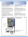
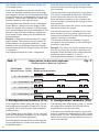
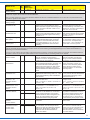
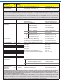
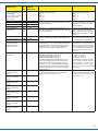
Bedienungsanleitung Operation Manual 5849 N Funktionsdecoder mit Kabel N Function decoder with wires 1. Wichtige Hinweise.......................................2 2. Funktionen...................................................2 3. Einbau und Anschluss................................. 5 4. Programmierung......................................... 8 5. Konfigurationsvariablen (CV)...................... 6. Lokadresse: Locomotive address: Eingebaut in Lok: Mounted in locomotive: 10 Betrieb.........................................................14 7.Fehlersuche & Abhilfe ................................. 14 8. Garantiebestimmungen...............................15 9. Herstellerhinweis.........................................15 10. Technische Daten........................................16 1. Important information..................................2 2. Functions.....................................................2 3. Installation and connection......................... 5 4. Programming...............................................8 5. Configuration variables (CV)....................... 6. = DCC MM 10 Operation ....................................................14 7. Trouble-shooting......................................... DC 14 8. Warranty......................................................15 9. Manufacturer´s note ....................................15 10. Technical data.............................................16 SuSi Rail Com DE EN 1. Wichtige Hinweise 1. Important information Bitte lesen Sie vor der ersten Anwendung des Produktes bzw. dessen Einbau diese Bedienungsanleitung aufmerksam durch. Bewahren Sie diese auf, sie ist Teil des Produktes. Please read this manual completely and attentively before using the product for the first time. Keep this manual. It is part of the product. Sicherheitshinweise Safety instructions Vorsicht: Risk of injury! Aufgrund der detaillierten Abbildung des Originals bzw. der vorgesehenen Verwendung kann das Produkt Spitzen, Kanten und abbruchgefährdete Teile aufweisen. Für die Montage sind Werkzeuge nötig. Due to the detailed reproduction of the original and the intended use, this product can have peaks, edges and breakable parts. For installation tools are required. Stromschlaggefahr! This decoder is equipped with integrated circuits (ICs). They are sensitive to static electricity. Do not touch the decoder or its components without discharging yourself first. Touching a radiator or other grounded metal part is sufficient for the needed discharge. Der Decoder ist mit integrierten Schaltkreisen (ICs) bestückt. Diese sind empfindlich gegen elektrostatische Aufladung. Berühren Sie daher den Decoder nicht, bevor Sie sich „entladen“ haben. Dazu reicht z. B. ein Griff an einen Heizkörper. Das Produkt richtig verwenden Dieses Produkt ist bestimmt: -Zum Einbau in Modelleisenbahn-Fahrzeuge. -Zum Betrieb mit einer Digitalzentrale, welche die Digitalsysteme Märklin-Motorola und/oder NMRA-DCC verwendet. -Zum Betrieb mit Gleichstrom, nicht für Wechselstrom geeignet. -Zum Betrieb in trockenen Räumen. 2 Caution: Verletzungsgefahr! Electrical hazard! Using the product for its correct purpose This product is intended: -For installation in model trains. -For operation with a digital command station delivering either NMRA DCC or Märklin Motorola. -For DC operation, not suitable for AC operation. Jeder darüber hinausgehende Gebrauch gilt als nicht bestimmungsgemäß. Für daraus resultierende Schäden haftet der Hersteller nicht. -For operation in dry rooms only. Packungsinhalt überprüfen Checking the package contents Kontrollieren Sie den Lieferumfang auf Vollständigkeit: When unpacking the contents check the package for completeness: - Funktionsdecoder mit Anschlusskabel -Anleitung -Function decoder with wire harness -Manual 2. Funktionen 2. Functions Programmierung der Funktionen: Programming the functions: Die Funktionen des Decoders richten Sie über die CV-Programmierung ein. Sämtliche Einstellmöglichkeiten finden Sie in Kapitel 5. Please program the functions of the decoder by means of CV programming. You can find all possible options in chapter 5. Using the product for any other purpose is considered incorrect. The manufacturer is not responsible for any damage resulting from the improper use of this product. Ansteuerung im Digitalbetrieb Digital operation Dieser Funktionsdecoder ist ein MultiprotokollDecoder, der sowohl Signale im DCC-Format als auch im Motorola-Format auswertet. Er erkennt automatisch, in welchem Format die Zentrale die Signale an seine Adresse sendet. This function decoder is a multi-protocol decoder supporting both DCC and Motorola. It auto-detects the data format transmitted by the command station. Der Adressumfang ist von dem Format abhängig, mit dem der Decoder angesteuert wird. Motorola-Format: Der Decoder beherrscht 255 Adressen. DCC- Format: 127 Basis-Adressen oder 10 239 erweiterte Adressen. Die Programmierung des Decoders erfolgt über die Einstellung der Konfigurationsvariablen (CVs, DCC-konform). Wahlweise ist auch über die Registerprogrammierung die Programmierung der CVs 1 bis 8 möglich. Ansteuerung im Analogbetrieb Den Funktionsdecoder können Sie auch in analogen Modellbahnanlagen einsetzen (Gleichspannung). Sobald Sie das Fahrzeug auf das Gleis stellen, erkennt der Decoder automatisch, ob er analog oder digital angesteuert wird, und stellt den entsprechenden Betriebsmodus ein. Die automatische Analogerkennung ist abschaltbar. Das Ein- und Ausschalten von Funktionsausgängen ist im Analogbetrieb nicht möglich. Sie können aber so programmiert werden, dass sie im Analogbetrieb aktiviert werden. Die eingestellten Funktionen (z. B. Blinken) bleiben dabei erhalten. Überlast-Schutz Sobald der zulässige Gesamtstrom des Decoders an den Funktionsausgängen (300 mA bzw. 500 mA) überschritten wird, schaltet der Decoder automatisch die Funktionsausgänge ab. Der Decoder versucht dann, die Ausgänge wieder zu aktivieren, zunächst ca. 0,1 Sekunden nach dem Überlastfall. Dieser Intervall wird aber zum Schutz des Decoders auf bis zu 2 Sekunden verlängert. Dabei dürfen die Ausgänge AUX1 und AUX2 zusammen mit maximal 300 mA belastet werden, wobei jeder dieser Ausgänge allein diesen Strom liefern kann. Entsprechendes gilt für die Ausgänge AUX3 und AUX4. Diese Ausgänge können jeweils maximal 500 mA dauernd schalten, in der Summe darf aber auch nur maximal 500 mA fließen. The number of supported addresses depends on the data format used. Motorola format: The decoder supports 255 addresses. DCC format: The decoder supports 127 base addresses or 10 239 extended addresses. Programming the decoder is done by setting the configuration variables (CVs, DCC compliant). Programming of CV 1 to 8 can also be done by physical register programming. Operation in analogue mode The function decoder can also be operated in analogue DC. When putting the vehicle on the track the decoder automatically detects if it is run in analogue or digital mode and sets the corresponding operating mode. The automatic detection of the analogue mode can be switched off. Switching function outputs is not possible in analogue mode. However, they can be programmed in such a way that they are activated in analogue mode. When special functions are dedicated to the output, they are activated, too. Overload protection As soon as the cumulative current of the function outputs exceeds the maximum permitted current (300 mA resp. 500 mA), the decoder automatically switches off the function outputs. The decoder tries to activate the outputs again, for the first time after about 0,1 seconds. This period is increased up to 2 seconds to protect the decoder. The total maximium current for the outputs AUX1 and AUX2 is 300 mA, even though each output can handle this current on its own. Accordingly behave outputs AUX3 and AUX4, except that here the maximum current of each output is 500 mA. However, the total current for AUX3 and AUX4 may not exceed 500 mA. Function outputs Four function outputs (max. total current 800 mA) enable you to control various electrical loads (e. g. lights, signal horn). Funktionsausgänge Vier Funktionsausgänge (max. Strom insgesamt 800 mA) ermöglichen den Anschluss von Verbrauchern (z. B. Licht, Signalhorn). 3 Die Ausgänge werden im DCC-Format über die Funktionstasten F0 bis F28 geschaltet. Im Motorola-Format werden die Ausgänge über die Funktionstasten F0 bis F4 geschaltet. Für F5 bis F8 siehe CV 113: Hier wird eine zweite Adresse definiert, auf der dann die Funktionen F1 bis F4 als F5 bis F8 gewertet werden. Die Zuordnung der Funktionstasten zu den Funktionsausgängen des Decoders ist frei wählbar. Sie können einem Funktionsausgang auch mehrere Funktionstasten zuordnen. Effekte der Funktionsausgänge Für alle Funktionsausgänge können einzeln die folgenden Effekte eingestellt werden: Dimmfunktion: Die Ausgangsspannung ist durch entsprechende Programmierung reduzierbar. Anwendungsbeispiel: Die für den Analogbetrieb vorgesehenen Birnen älterer Fahrzeuge können gedimmt werden und müssen dann nach dem Einbau des Decoders nicht ausgetauscht werden. Blinkfunktion: Die Frequenz des Blinkens lässt sich einstellen. Entkuppeln: Bei dieser Betriebsart wird für eine einstellbare Zeit die volle Spannung an den Ausgang gelegt. Nach dieser Zeit fällt die Spannung auf den Wert zurück, der für die Dimmfunktion eingestellt wurde. Anwendungsbeispiel: Ansteuerung einer TelexKupplung. SUSI-Schnittstelle An den Decoder können Sie ein SUSI-Modul anschließen, das auch über den Decoder programmiert werden kann. Der Decoder überträgt den Zustand der Funktionen und die an der Zentrale eingestellte Fahrstufe an das SUSI-Modul. Dadurch werden geschwindigkeitsabhängige Funktionen des SUSI-Moduls beeinflusst (z. B. Motorgeräusch). Rückmeldung mit RailCom® RailCom ist ein Protokoll zur bidirektionalen Kommunikation in digitalen Modellbahnanlagen, die im DCC-Format gesteuert werden. Es ermöglicht z. B. die Rückmeldung der Adresse und der CVEinstellungen von den Decodern zur Digitalzentrale oder zu speziellen Empfängerbausteinen (Detektoren). Die Decoder müssen die sogenannten RailCom-Messages senden können. 4 Der Decoder sendet fortlaufend die Basis-, erweiterte oder Consist-Adresse an die Detektoren (sog. RailCom Broadcast Datagramm) und übermittelt auf einen entsprechenden RailCom-Auslesebefehl hin einen CV-Wert. In DCC the outputs are switched with the function buttons F0 – F28. In Motorola format only F0 to F4 are available. For F5 to F8 see CV 113: A second address can be programmed into this CV, on which F1 to F4 now act as F5 to F8. The decoder supports free function mapping. That means, any output can be assigned to any function button. It is also possible to assign a function to several function buttons. Effects of function outputs The following effects can be separately set for each function output: Dimming function: The output voltage can be reduced by programming. Application example: The lamps installed in analogue locomotives are usually rated 12V. In digital mode a higher voltage is applied to the lamps. Therefore it is recommended to dim the light outputs and thus avoid the need for changing the lamps. Blinking function: The frequency can be adjusted. Uncoupling: In this mode the full voltage is applied to the output for a certain time. After that time has elapsed, the voltage is reduced to the dimming level. Application example: Controlling a Telex coupler. SUSI-interface You may connect a SUSI-module to the decoder. This module can also be programmed via the decoder. The decoder transmits the speed step and the status of functions to the SUSI-module. Thus it is possible to influence speed dependent effects of the SUSI-module (e. g. engine sound). Feedback with RailCom® RailCom is a protocol for bi-directional communication in digital model railways operating in DCC. It allows e. g. feedback of the address and CV values from the decoder to the command station or to special receivers (so called detectors). The decoders must be able to transmit RailCom messages. The decoder continuously transmits the (basic, extended or consist) address to the detectors (so called RailCom broadcast datagram) and transfers a CV message on a DCC CV read-out command. Das Versenden von RailCom-Messages ist nur in Anlagen möglich, in denen ein DCC-Signal an den Schienen anliegt. Daher ist die Nutzung der RailCom-Funktion in einer reinen Motorola-Umgebung nicht möglich. The transmission of RailCom messages is only possible in DCC operated layouts. RailCom must be avaiable at the tracks. In pure Motorola environments the utilisation of RailCom is not possible. 3. Einbau und Anschluss 3. Installation and Connection Vorsicht: Caution: Die Entstörmittel, die in der Zuleitung angebracht sind, dürfen nicht entfernt werden! Wird nur ein Teil entfernt, kann es zu erheblichen elektrischen Störungen kommen. Any interference suppression devices in the vehicle must not be removed! If even one part is removed, it may cause considerable electrical interference! Anschluss von Verbrauchern an die Funktionsausgänge Connecting electrical loads to the outputs Prüfen Sie vor dem Anschluss von Zusatzgeräten an die Funktionsausgänge, ob der Strom aller Funktionen zusammen unterhalb des maximal zulässigen Wertes von 300 mA (für AUX1 und AUX2) und der Strom für AUX3 und AUX4 500 mA nicht dauerhaft übersteigt. Before connecting accessories to the function outputs check if the total current is below the maximum permissible value of 300 mA (for AUX1 and AUX2) and that the current for AUX3 and AUX4 remains below 500 mA (continuous). Entfernen Sie eventuell vorhandene Dioden in den Zuleitungen zu den Lampen. Abb. 1 Please disconnect any diodes in the leads to the lamps. Fig. 1 Anschlussschema / Wiring connections orange / orange AUX 4 grau / grey AUX 3 Gleis 2 rot / red weiß / white Gleis 1 AUX 1 gelb / yellow AUX 2 schwarz / black Vers. blau / blue Schließen Sie die Verbraucher wahlweise an „Vers.“, z. B. für volle Helligkeit von LEDs oder Glühlampen, oder an eine Gleisseite an (verminderte Helligkeit). Connect electric loads either to „Vers.“, e. g.: for full brightness of LEDs or bulbs, or to one rail (for reduced brightness). Anschluss Connector Farbe Funktion Colour Function AUX1 weiß max. 300 mA white max. 300 mA AUX2 gelb max. 300 mA yellow max. 300 mA AUX3 grau max. 500 mA grey max. 500 mA AUX4 orange max. 500 mA orange Vers. blau gemeinsamer Rückleiter Gleis 2 rot Radstromkontakt rechts Gleis 1 schwarz Radstromkontakt links max. 500 mA blue common return red wheel wiper right black wheel wiper left 5 Schließen Sie die Zusatzgeräte an die Funktionsausgänge AUX1 bis AUX4 des Decoders an. Die Zuordnung der Funktionsausgänge zu den Funktionstasten kann durch Programmierung des Decoders geändert werden. Wenn der Rückleiter des Zusatzgerätes bereits mit Fahrzeugmasse verbunden ist, ist der Anschluss damit fertiggestellt. Andernfalls schließen Sie den jeweiligen Rückleiter der Zusatzgeräte an den Versorgungsanschluss für alle Funktionen des Decoders „Vers.“ an. Vorsicht: If the return conductor of the accessory is already connected to vehicle ground (common), wiring is complete. If not, connect the second pole of the accessory to the common connection ”Vers.” of the decoder. Caution: Kurzschlussgefahr! Risk of short-circuit! Wenn Sie die Zusatzgeräte an den Rückleiter für alle Funktionen (Punkt „Vers.“) anschließen, müssen Sie sie isolieren. Die Zusatzgeräte dürfen keinen Kontakt zu Metallteilen des Fahrzeugs haben. Kurzschlussgefahr! If you connect the accessories to the return conductor for all functions (“Vers.”), the accessories must be insulated from the chassis. They should not make contact with any metal parts of the vehicle at all. Risk of short circuit! Der Rückleiter für alle Funktionen (Punkt „Vers.“) darf auf keinen Fall mit Fahrzeugmasse verbunden werden. Der Decoder wird bei Inbetriebnahme zerstört. Never connect the return conductor for all functions (“Vers.”) to vehicle ground. The decoder will be damaged when applying power. Werkseitige Decodereinstellungen Factory default settings Ab Werk ist der Decoder wie folgt programmiert: -F4 schaltet AUX4 The factory settings are as follows: -F1 controls AUX1 -F2 controls AUX2 -F3 controls AUX3 -F4 controls AUX4 Anschluss von LEDs Connecting the LEDs Die Funktionsausgänge des Funktionsdecoders schalten gegen Decodermasse. Daher müssen am Ausgang der Funktionsausgänge die Kathoden („Minusanschluss“) der LEDs angeschlossen werden. The return of the function outputs of the decoder must be connected to the decoder ground (“Vers.”). For that reason you must connect the cathodes (-) of the LEDs to the function outputs. -F1 schaltet AUX1 -F2 schaltet AUX2 -F3 schaltet AUX3 Vorsicht: Wenn Sie LEDs einsetzen, müssen Sie diese immer über einen Vorwiderstand betreiben! Die Vorwiderstände sind je nach Strom und Bauform der Leuchtdioden unterschiedlich. Ermitteln Sie die richtigen Werte oder erfragen Sie sie beim Kauf. Sie können mehrere LEDs an einen Ausgang parallel anschließen. Dabei benötigt jede Diode einen eigenen Vorwiderstand. Wenn Sie mehrere LEDs an einen Ausgang in Reihe anschließen, reicht ein Vorwiderstand aus. Technisch bedingt fließen durch die Verbraucher an AUX3 und AUX4 sehr geringe Ruhe6 Connect accessories to the outputs AUX1 to AUX4 of the decoder. The assignment of the function outputs to the function keys (function mapping) will be done by programming the decoder. Caution: LEDs must always be wired via a serial resistor! The resistor value depends on the type and current draw of the LEDs. Determine the appropriate value or enquire when purchasing the LEDs. You can connect several LEDs in parallel to each output. In this case every LED must have its own serial resistor. If you connect several LEDs to one output in series, only one serial resistor is required. For technical reasons a low current will always flow through the electric loads at AUX3 and AUX4 (LEDs might even show a slight glow under certain cirumstances). Use the out- ströme (LEDs können unter Umständen bereits leicht glimmen). Verwenden Sie die Ausgänge AUX1 und AUX2 für LEDs und AUX3 und AUX4 für leistungsstärkere Verbraucher wie z. B. Telex-Kupplung, Glühlampen etc. puts AUX1 and AUX2 for LEDs and AUX3 and AUX4 for heavier loads such as a Telex coupler, bulbs, etc. Anschluss eines SUSI-Moduls Connecting SUSI-modules Der Decoder hat vier Lötpads für den Anschluss eines SUSI-Moduls. Die Belegung der Anschlüsse entnehmen Sie bitte der Abb. 2. The decoder has four soldering pads for connecting a SUSI-module. The allocation of each pad is shown in fig. 2. Anschluss eines Stützkondensators Connecting a buffer capacitor In Fahrabschnitten mit schlechtem Kontakt kann die Stromversorgung des Decoders immer wieder kurz unterbrochen werden. Zwischen den Punkten „Elko-“ und „Elko+“ können Sie einen Stützkondensator (z. B. 100 μF/25 V) anlöten, der die Stromversorgung verbessert (s. Abb. 2). On tracks with poor contact the power supply to the decoder may be momentarily interrupted. In order to resolve this issue you may solder a buffer capacitor to the pads “Elko-“ and “Elko+” (e. g. 100μF/25 V). Also refer to fig. 2. Befestigung des Decoders Installing the decoder Nach Fertigstellung aller Anschlüsse sollten Sie den Funktionsdecoder befestigen, sofern das Fahrzeug nicht über einen geeigneten Einbauraum verfügt. Dies kann z. B. mit doppelseitigem Klebeband erfolgen. After having made all connections you should fix the decoder in the locomotive. If there is no specific decoder compartment in the locomotive you may simply use some double-sided adhesive tape. Abb. 2 Anschluss von SUSI-Modulen / Wiring of SUSI-modules und Stützkondensator and buffer capacitor Fig. 2 SUSI GROUND SUSI DATA SUSI CLOCK SUSI PLUS Widerstand / resistor 10 ... 100 Ohm Typ 0207 oder 0411 Elko + Elektrolytkondensator electrolytic capacitor 100 – 470 µF/>25 V Bei Werten bis zu 10 Ohm kann evt. auf die Diode verzichtet werden. For resistor ratings of up to 10 Ohms the diode may be omitted. Diode Typ 1N4001 o. ä. oder B160; Gl 10 7 4. Programmierung 4. Programming Bevor Sie mit dem Programmieren des Decoders beginnen, müssen die Verbraucher an den Decoder angeschlossen sein, da sonst keine Rückmeldung zur (DCC-) Zentrale erfolgen kann. Sie können in CV 50 einstellen, welche Ausgänge für diesen Zweck verwendet werden sollen. Before starting the programming you should connect some load to the decoder in order to assure the necessary feedback from the decoder to the (DCC) command station. You can set up in CV 50 which outputs should be used for this purpose. Wenn Sie den Decoder mit einer Motorola-Zentrale programmieren wollen, sollten Sie an die Ausgänge AUX1 und AUX2 Beleuchtungen anschließen, da die Lok den Wechsel in den Programmiermodus und die Übernahme der Eingaben durch das Blinken der Beleuchtung an diesen Ausgängen quittiert. Im DCC-Format können Sie die Konfigurationsvariablen (CVs) am Programmierausgang üblicher Zentralen programmieren, die Hauptgleisprogrammierung ist ebenfalls möglich. Im Motorola-Format werden die Einstellungen in sogenannte Register programmiert, die Zählweise ist mit der der CVs identisch. Programmierung mit DCC-Zentralen Von der Zentrale aus können Sie die Konfigurationsvariablen (CVs) des Decoders programmieren. Beachten Sie dazu den betreffenden Abschnitt in der Bedienungsanleitung Ihrer Zentrale, in der die byteweise Programmierung der CV-Variablen beschrieben ist. Programmierung mit Motorola-Zentralen Stellen Sie die Lok auf ein Gleis, das mit dem Gleisausgang der Zentrale verbunden ist. Es darf kein weiteres Fahrzeug auf dem Gleis stehen, da der darin befindliche Decoder sonst ggf. ebenfalls programmiert wird. Tipp: Wenn Sie eine Zentrale einsetzen, die sowohl das DCC- als auch das Motorola-Format sendet, ist die Programmierung des Decoders im DCC-Format empfehlenswert. Sie können den Decoder nach dem Programmieren auch im Motorola-Format ansteuern. Führen Sie einen Reset an der Zentrale durch (durch gleichzeitiges längeres Drücken der Tasten „Stop“ und „Go“) oder schalten Sie die Zentrale kurz aus und wieder ein. Wählen Sie zunächst die aktuelle Adresse des Decoders oder die Adresse „80“ (wenn Sie z. B. die aktuelle Adresse des Decoders nicht kennen). Bei der Auslieferung hat der Decoder die Adresse „3“. Stellen Sie alle Funktionen (Funktion, F1 bis F4) auf „Off“. 8 Should you intend to program the decoder with a Motorola central unit you should always connect the lighting to the outputs AUX1 and AUX2. The locomotive confirms the change into the programming mode and the acceptance of programming commands by flashing the lights. In DCC format you can program the configuration variables (CVs) at the programming output of typical central units, this can also be done by “Programming on the Main” (POM). In the Motorola format the settings are saved in so called registers. The method of counting is the same as with the CVs. Programming with a DCC command station You can program the configuration variables (CVs) of the decoder from the command station. Also take note of the relevant chapter of the manual of your command station where the byte-wise programming of (CVs) is explained. Programming with Motorola central units Put the locomotive onto a track section connected to the central unit’s track output. Make sure no other vehicle is located on the track as the decoder in that vehicle will also be programmed. Hint: If you use a command station supplying both DCC and Motorola signals it is recommended to program the decoder in DCC mode. After having completed programming the decoder will also operate in the Motorola mode. Reset the central unit (by simultaneously pushing the buttons “Stop” and “Go” for some time) or switch off the central unit for a moment and then on again. Next you select the current address or address “80” (for instance, if you do not know the current address of the decoder). The manufacturer´s default setting is “3”. Set all functions to ”Off” (function, F1 to F4). Push the “Stop” button at the central unit. Next, operate the direction switch and hold it in that position briefly while pushing the “Go” button. As Drücken Sie als nächstes die Taste „Stop“ der Zentrale. Betätigen Sie dann den Richtungsumschalter und halten Sie ihn gedrückt. Drücken Sie kurz die Taste „Go“. Sobald die Beleuchtungen des Fahrzeugs, die an den Ausgängen AUX1 oder AUX2 angeschlossen sind, blinken (nach ca. 2 Sekunden), befindet sich der Decoder im Programmiermodus und Sie können den Umschalter loslassen. Im Programmiermodus können Sie die Register des Decoders wie folgt programmieren: 1.Wählen Sie ein Register zum Programmieren aus, indem Sie die Nummer des Registers als Motorola-Lokadresse an Ihrer Zentrale eingeben. Beachten Sie, dass bei manchen Zentralen eine führende „0“ eingegeben werden muss. 2.Betätigen Sie den Richtungsumschalter. Die Beleuchtung blinkt schneller. 3.Geben Sie den gewünschten Wert des Registers ein, indem Sie den Wert als Motorola-LokAdresse an Ihrer Zentrale eingeben. Der Wert Null ist über die Motorola-Adresse 80 erreichbar. 4.Betätigen Sie den Richtungsumschalter erneut. Die Beleuchtung fängt wieder an zu blinken. Wiederholen Sie die Punkte 1 bis 4 für alle Register, die Sie programmieren wollen. Um ein Register zum Programmieren auszuwählen oder einen Wert für ein Register einzugeben, müssen Sie die eingebene Zahl immer wie beim Auswählen einer Lokadresse an Ihrer Zentrale bestätigen. Die Beleuchtung zeigt an, welche Eingabe der Decoder erwartet: -Beleuchtung blinkt: Eingabe einer Registernummer. -Beleuchtung blinkt schneller: Eingabe des Wertes eines Registers. Zum Beenden des Programmiermodus drücken Sie „Stop“. Tipp: Programmierung von Werten größer 80 im „Motorola-Langmodus“. Um vom klassischen Motorola-Programmiermodus in den erweiterten oder Motorola-Langmodus zu gelangen, programmieren Sie zunächst wie oben beschrieben Register 7 mit Wert 7. Daraufhin blinken die Ausgänge AUX1 und AUX2 zwei mal lang, gefolgt von einer langen Pause, dann wiederholt sich das zweimalige lange Blinken und so weiter. Der Decoder erwartet jetzt die Hunderter- und die Zehnerstelle des Registers, dessen Wert Sie programieren wollen, als Wert. Geben Sie die entsprechende Zahl auf der Zentrale ein und bestätigen Sie durch Umschaltklick. soon as the lamps connected to the outputs AUX1 or AUX2 of the decoder start flashing (after ca. 2 seconds) the decoder is in programming mode and you may release the direction switch. In programming mode you can program the registers of the decoder as follows: 1.Choose the register you want to program by entering the register´s number as Motorola locomotive address on your central unit. Please note that with some central units a leading “0” has to be entered. 2.Press the direction switch. The lights flash faster. 3.Set the desired value of the register by setting the register´s value as Motorola locomotive address on your central unit. 4.Press the direction switch again. The value zero can be reached via the Motorla address 80. The lights start flashing again. Repeat the steps 1 to 4 for all registers you want to program. In order to choose a register for programming or to enter a value for a register you have to confirm the entered number like selecting a Motorola locomotive address. The lights show which kind of entry the decoder expects: -Lights flash: Entry of a register number. -Lights flash faster: Entry of a register value. In order to terminate the programming mode simply push “Stop”. Hint: Programming values higher than 80 in the “Motorola extended mode” In order to change form the classical Motorola mode into the extended mode program first register 7 to the value of 7 as described above. Subsequently the outputs AUX1 and AUX2 start blinking twice long followed by a pause. This pattern is then repeated. Now the decoder expects the hundred and the decade value of the register you wish to program as a value. Enter the appropriate number on your central unit and confirm by pressing the direction switch. Then the decoder blinks long once followed by a long pause. This rhythm is continually repeated. Now the decoder expects the input for the unit position. Enter the appropriate number on your central unit and confirm by pressing the direction switch. Now that the decoder “knows” the name of the register the content can follow. 9 Der Decoder blinkt nun einmal lang, gefolgt von einer langen Pause. Auch dieser Rhythmus wiederholt sich kontinuierlich. Der Decoder erwartet jetzt die Einerstelle des Registers. Geben Sie die entsprechende Zahl auf der Zentrale ein und bestätigen Sie durch Umschaltklick. Jetzt ist dem Decoder der „Name“ des Registers bekannt, nun folgt der Inhalt. Dies signalisiert der Decoder durch zweimaliges kurzes Blinken, gefolgt von einer langen Pause. Geben Sie wieder die Hunderter- und Zehnerstelle ein und bestätigen Sie durch Umschaltklick. Der Decoder zeigt durch kurzes Blinken, gefolgt von einer langen Pause, dass er die Einerstelle des Wertes erwartet. Beispiel: In Register 94 soll der Wert 237 eingetragen werden. Der Decoder soll sich bereits für dieses Beispiel im Langmodus befinden – umgeschaltet durch das klassische Motorola-Programmierverfahren mittels des Prgammierens von Wert 7 in Register 7. Die Programmierfolge ist in Abb. 3 dargestellt. Enter the relevant number on the command station and confirm by activating the change-of-direction command. The decoder blinks long followed by a long pause. This rhythm is repeated continuously. The decoder now expects the input for the unit position. Enter the relevant number on the command station and confirm by activating the change-of-direction command. Now the decoder knows the “name” of the register after which follows the content. The decoder indicates its readiness by two short blinks followed by a long pause. Again enter the hundred and decade and confirm by activating the change-of-direction command. The decoder indicates its readiness to receive the value for the unit position by short blinking followed by a long pause. Example: The value 237 shall be written into register 94. Assuming the decoder is already in the extended mode activated by the classic Motorola method by setting register 7 to value 7. The programming sequence is shown in fig. 3. Abb. 3 Blinkrythmen im Motorola-Langmodus Fig. 3 Blinking rhythm in Motorola long mode Zahleingabe Aktion Numeric value Action Blinkmuster Blinking characteristics 09 Umschaltklick / direction click 04 Umschaltklick / direction click 23 Umschaltklick / direction click 07 Umschaltklick / direction click 5. Konfigurationsvariablen (CVs) 5. Configuration variables (CVs) In der folgenden Tabelle (siehe ab Seite 11) sind alle Konfigurationsvariablen für das DCC-Format aufgeführt, die für den Decoder 5849 eingestellt werden können. The following table (beginning on page 11) shows all configuration variables for DCC that can be programmed for the decoder 5849. In der Tabelle sind in der Spalte „CV-Nr.“ die Nummern der Konfigurationsvariablen für die Programmierung im DCC-Format angegeben. Die Defaultwerte sind die Werte, die bei Auslieferung eingestellt sind, und die nach einem Reset eingestellt werden. 10 In the table you will find the numbers of the configuration variables for programming in DCC format in the column “CV No.”.The default values are the values set ex factory and also whenever you do a reset of the decoder. Name der CV Name of CV CVNr. No. Eingabewerte Erläuterungen/Hinweise (Default) value range Remarks Basisadresse 1 1 … 255 (3) Wertebereich bei DCC: 1 … 127 Range of values in DCC: 1 ... 127 Primary address Hinweis: Wenn für die Basisadresse ein Wert > 127 programmiert wird und die Verwendung der erweiterten Adresse in CV 29 ausgeschaltet ist, reagiert der Decoder nicht auf DCC-Befehle. Hint: If a value higher than 127 is set for the basic address and the use of extended addresses in CV 29 is set to off, the decoder does not react to signals in DCC format! Startspannung 2 0 … 63 (1) Minimale Geschwindigkeit der Lokomotive. The minimal speed of the locomotive. Starting voltage Beschleunigungsrate Acceleration rate 3 0 … 63 (8) Wartezeit, die beim Beschleunigen der Lok Delay before the switching to the jeweils vor dem Hochschalten zur nächst next higher speed level when the höheren Fahrstufe vergeht. Berechnung: Zeit loco is accelerating. Calculation: time zw. min. und max. Fahrstufe = Wert von ca. between min. and max. speed steps = CV 3 x 0,9 sec. value of ca. CV 3 x 0,9 sec. Delay before the switching to the next Bremsrate 4 0 … 63 (6) Wartezeit, die beim Abbremsen der Lok Deceleration rate jeweils vor dem Herunterschalten zur nächst- lower speed level when the locomotive niedrigeren Fahrstufe vergeht. Berechnung is braking. The delay is calculated as described in CV 3. wie unter CV 3. Höchstgeschwindigkeit 5 0 … 255 (255) CV 2, 5 und 6 werden für die Berechnung CV 2, 5 and 6 are used in the calculaMax. speed der Geschwindigkeitskennlinie verwendet, tion of the motor voltage, if bit 4 in CV wenn Bit 4 im CV 29 auf Null steht. Wenn 29 is set to zero. If the speed step die Fahrstufentabelle (CV 67 – 94) im CV table in CV 67 – 94 is activated in CV Mittelgeschwindigkeit 6 0 … 255 (110) 29 auf aktiv eingestellt ist, hat CV 6 keine 29, the value in CV 6 is ignored. Middle speed Bedeutung. CV 2 bis CV 6 werden für die Berechnung der Geschwindigkeit verwendet, um die passenden geschwindigkeitsabhängigen Geräuscheffekte an das SUSI-Modul übertragen zu können. Diese CVs sowie weitere geschwindigkeitsbezogene CVs dienen ausschließlich zur Steuerung von SUSI-Sound-Modulen. CV 2 to CV 6 are used for the calculation of the speed of the locomotive, so that the SUSI-module can generate sound effects based on the speed. These CVs and further speed-based CVs are used exclusively for controlling SUSI sound modules. Versionsnummer 7 (1) Nur lesbar! Read only! Version number Motorola: erweiterte Programmierung. Motorola (extended programming): Schreiben von Wert 7 ermöglicht erweiterte Writing of value 7 allows extended Programmierung unter Motorola. programming in motorola protocol. Hersteller 8 (109) Nur lesbar! Read only! Manufacturer Reset auf Werkseinstellungen: Schreiben von Factory reset writing a value of 8 Wert 8 setzt alle Werte auf Auslieferungsresets all CVs to the factory default zustand zurück. Schreiben von Wert 9 setzt settings. Writing 9 resets all CVs alle Werte außer Lokadresse, CV 29 und except the address, CV 29 and the Fahrstufentabelle auf Auslieferungszustand speed step table. zurück. Zwangsbremsung 11 0 … 255 (100) Autom. Halt bei Signalausfall von der Contains the maximum time period (in Packet time-out Digitalzentrale. Berechnung: Wert x 0,1 = Zeit 0,1 sec.) that the decoder will maintain [sec] bis Stop-Auslösung. Wert 0 deaktiviert its speed without receiving a valid dieses Feature. packet addressed to it. Funktionen im Analog13 0 … 255 (0) Bestimmt, welche Funktionen im AnalogbeIndicates the status of the functions in betrieb F1 – F8 trieb immer aktiv sind. analogue mode. Analogue function F1 ein = 1; F2 ein = 2; F3 ein = 4; F4 ein = 8 F1 on = 1; F2 on = 2; F3 on = 4; F4 on status … F8 ein = 128 = 8; ... F8 on = 128 Funktionen im Analog14 0 … 63 (3) Berechnung wie bei CV 13. Calculated as in CV 13. betrieb F0, F9 – F12 F0 vorwärts ein = 1; F0 rückwärts ein = 2; F0 forward on = 1; F0 backwards on = Analogue function F9 ein = 4; F10 ein = 8; F11 ein = 16; 2; F9 on = 4; F10 on = 8; F11 on = 16; status F12 ein = 32 F12 on = 32 Erweiterte Adresse 17 192 … 255 (192) Erlaubt Adresse über 127 wenn die lange Allows addresses above 127 if the Extended address Adresse im CV 29 aktiviert ist, nur für DCC. long address is activated in CV 29, in Bei den meisten Zentralen ist es möglich, DCC. Most command stations permit 18 0 … 255 (0) erweiterte Adressen direkt einzugeben. Die entering long addresses directly. In CVs 17, 18 und 29 werden dann von der this case the CVs 17, 18 and 29 are Zentrale automatisch richtig eingestellt. set automatically to the proper values. Mehrfachtraktions19 1 … 127 (0) Adresse für die Lokomotive im Mehrfachtrak- Address for locomotives in multiadresse tionsmodus. traction mode. Consist address Funktionen im Mehr21 0 … 255 (0) Berechnung wie bei CV 13 und 14. Bit auf Calculated as in CV 13 and 14. Bit fachtraktions-Modus Wert 0 bedeutet, dass die entsprechende with a value of 0 indicates that the 22 0 … 63 (0) Consist mode Funktion nur über die Lokadresse gesteuert function can only be controlled by the function status werden kann. Bit auf Wert 1 erlaubt, die locomotive address. A value of “1” Funktionen über die Mehrfachtraktionsallows the function to be controlled by adresse zu schalten the consist address. 11 Name der CV Name of CV CVNr. No. Eingabewerte Erläuterungen/Hinweise (Default) value range Remarks Bremsverhalten bei 27 0, 16, 32, 48 (16) Kein Bremsen bei Gleichspannung = 0 No braking with D.C. = 0 Gleichspannung Bremsen bei Gleichspg. in Gegenricht. = 16 BremBraking with D.C. in reverse dir. = 16 Decoder automatic sen bei Gleichspg. in Fahrtricht. = 32 Braking with D.C. in actual dir. = 32 stopping configuration Hinweis: Standardmäßig wird bei Anliegen einer Gleichspannung am Gleis in den Analogbetrieb umgeschaltet. Setzen Sie den Decoder auf einer Anlage mit einer Bremsstrecke ein, die auf dem Anlegen einer Gleichspannung basiert (z. B. Märklin-Bremsstrecke), muss das Umschalten auf Analogbetrieb verhindert und sichergestellt werden, dass die Lok wie gewünscht auf die Bremsstrecke reagiert. Wird für den Decoder ein Bremsen bei positiver oder negativer Gleichspannung eingestellt, wird automatisch die Analogerkennung ausgeschaltet. Hint: It is standard to switch over into analogue mode when applying a DC voltage at the rails. In case that the decoder is run in a layout with a braking route based on applying a DC voltage (e. g. Märklin-braking route), the locomotive has to be prevented from changing over into analogue mode and it has to be ensured that the locomotive reacts as expected on the braking route. When braking with positive or negative DC voltage is set for the decoder, the analogue recognition is switched off automatically. Bi-directional communication: RailCom 28 0 … 3 (3) Bidirektionale Kommunikation: disabled = 0, RailCom inaktiv = 0, Adresse senden = 1, Address broadcast enabled = 1, Acknowledge and POM enabled = 2 Quittung und POM aktiv = 2 Konfiguration 29 (30) Bit Wert Configuration direction normal normale Richtung 0 0 direction inverted umgekehrte Richtung 1 14 speed steps 14 Fahrstufen, 0 1 28 and 128 speed steps 28 und 128 Fahrstufen 2 no analogue operation nur digital erlaubt 0 2 analogue operation allowed analog + digital erlaubt 4 no RailCom kein Railcom 0 3 RailCom allowed Railcom eingeschaltet 8 Motorkennlinie aus CV 2, 5, 6 berechnet speed steps set by CV 2, 5, 6 0 4 speed steps set by CV 67-94 Motorkennlinie in CV 67 – 94 16 short address in CV 1 kurze Adresse in CV 1 0 5 long address in CV 17-CV 18 lange Adresse in CV 17+18 32 Fehler-Information 30 (0) Nur lesbar oder auf 0 zurücksetzbar Only writable with the value “0” Error information Bit 0: Abgeschaltet wegen Überhitzung Bit 0: Overtemperature Bit 1: Überlastung an AUX5 und AUX6 Bit 1: Overload on AUX5 and AUX6 Bit 2: Überlastung an Funktionsausgängen AUX1 Bit 2: Overload on the function bis AUX4 outputs AUX1 to AUX4 F0 in Vorwärtsfahrt 33 0 … 31 (0) Definiert, welche Funktionstasten welche DecodIndicates which function inputs erausgänge steuern. control which decoder outputs. F0 in Rückwärtsfahrt 34 0 … 31 (0) Wert 1: AUX1 Value 1: AUX1 F1 35 0 … 31 (1) Wert 2: AUX2 Value 2: AUX2 F2 36 0 … 31 (2) Wert 4: AUX3 Value 4: AUX3 F3 37 0 … 31 (4) Wert 8: AUX4 Value 8: AUX4 F4 38 0 … 31 (8) Bsp.: AUX2 mit F5 schalten CV 39 = 2 Example: to control AUX2 with F5: Bsp.: AUX1 und 2 mit F6 schalten CV 40 = 3 CV 39 = 2 F5 39 0 … 31 (16) (= 1+2) to control AUX1 and AUX2 with F6: ... ... (CV 33 bzw. 34 = Wert 0 um eine Schaltung mit F0 CV 40 = 3 (= 1+2) F12 46 0 … 31 (0) zu verhindern) (CV 33 resp. 34 = 0 to hinder F0) F13 147 0 … 31 (0) F14 148 0 … 31 (0) ... ... 0 … 31 (0) F28 162 0 … 31 (0) Fahrverhalten Control settings 47 0 ... 3 (0) Bit Wert Verhalten nach Stromunterbrechung: 0 0 Letzte Geschwindigk. sofort aufnehmen 1 Beschleunigungsrampe verwenden Kein Nothalt bei Richtungswechsel 1 0 2 Nothalt bei Richtungswechsel 0 = DCC; 1 = Motorola Behaviour after power-fail: resume speed immediately accelerating gradually Gradual halting on dir. switch Emergency stop on dir. switch 0 = DCC; 1 = Motorola Vorzusgprotokoll 48 0, 1 (0) Preferred protocol Multiprotokoll 49 0 … 255 (50) Wartezeit bei Protokollwechsel Time until switching protocols Multi-protocol Wenn der Decoder nicht mehr unter seinem bisherigen Protokoll adressiert wird, dann versucht er das alternative Protokoll. Er kann während des Betriebs zwischen DCC und MM umschalten. Die Zeit ist 0,1 Sekunden x CV (Bsp.: Wert 20 = 2 Sek.) Wenn der Decoder eine Adresse auch im alternativen Protokoll nicht findet, dann wird er gestoppt. Wert 0 bedeutet, dass diese Funktion nicht aktiv ist und der Decoder während des Betriebs das Protokoll nicht wechselt. Einige Zentralen, z. B. EcoS, adressieren gestoppte Loks nicht dauerhaft. In solchen Fällen ist es empfehlenswert diese CV auf 0 zu setzen. 12 If the decoder is no longer addressed in its actual digital protocol for a time period, it tries the alternative, by switching between DCC and MM. The time is 0,1 seconds x CV 49 (e. g. a value of 20 means 2 seconds). If the decoder is not addressed even in the alternative protocol, it stops. A value of 0 means this function is not active, and the decoder does not switch protocols while in operation. Some digital stations, like the EcoS, do not address stopped locomotives periodically, in this case it is recommended to turn this feature off. Name der CV Name of CV Aktive Ausgänge bei DCC-Programmiergleis: Acknowledge Active outputs on DCCprogramming-trade: acknowledge Dimmen für AUX1 Dimmen für AUX2 Dimmen für AUX3 Dimmen für AUX4 Fahrstufentabelle Speed table CVNr. No. Eingabewerte Erläuterungen/Hinweise (Default) value range 50 0...63 (15) 57 58 59 60 67 … 94 0 … 15 (15) 0 … 15 (15) 0 … 15 (15) 0 … 15 (15) 0 … 255 Benutzer Variabel 1 105 0 … 255 Benutzer Variabel 2 106 0 … 255 Motorola Funktionsadresse Motorola secondary function address 113 0 … 255 Entkuppeln Uncoupling 117 0 … 15 (0) Blinkperiode für AUX1 Blinking period for AUX1 Einschaltzeit für AUX1 Blinking on time for AUX1 Blinkperiode für AUX2 Blinking period for AUX2 Einschaltzeit für AUX2 Blinking on time for AUX2 Blinkperiode für AUX3 Blinking period for AUX3 Einschaltzeit für AUX3 Blinking on time for AUX3 Blinkperiode für AUX4 Blinking period for AUX4 Einschaltzeit für AUX4 Blinking on time for AUX4 123 0 … 255 (0) 124 0 … 255 (0) Remarks Definiert, welche Ausgänge für das DCC-Programmiergleis verwendet werden. AUX1 = 1 AUX2 = 2 AUX3 = 4 AUX4 = 8 Reduzierung der Spannung, die am Ausgang anliegt. Der Wert “0” entspricht der kleinsten, 15 der maximalen Spannung. Indicates which outputs are used for the DCC programming track. AUX1 = 1 AUX2 = 2 AUX3 = 4 AUX4 = 8 Reduces the voltage on the function output. A value of “0” corresponds to the smallest, a value of “15” to the maximal voltage. Ein Wert von “0” entspricht einer Spannung von 0, “255” der maximalen Spannung. Nur aktiv, wenn Bit 4 im CV 29 gesetzt ist. A value of “0” corresponds to zero voltage on the motor, a value of “255” corresponds to the maximum voltage. Only used if bit 4 in CV 29 is set to “1”. The users can store values for their own purposes here, it has no effect on the functionality of the decoder. Setting an address in this CV allows the functions F1 – F4 for this loco address to be used as functions F5 – F8. This feature makes it possible to use 8 functions even with digital stations which can control only 4 functions. Uncoupler on AUX1: 1 Uncoupler on AUX2: 2 Uncoupler on AUX3: 4 Uncoupler on AUX4: 8 If an uncoupler is set, the decoder output is set to maximum voltage to open the coupling, and after a time period (defined in CV 124 – 134) the output is set to the dimmed state (CV 57 – 62). Hier kann der Anwender eigene Werte speichern, es hat keine Auswirkungen auf die Funktionalitäten des Decoders. Durch Eingabe einer beliebigen Adresse werden die Funktionen F1 – F4 für diese Motorola-Adresse als Funktionen F5 – F8 gewertet. So kann man 8 Funktionen aufrufen, auch mit Zentralen die nur 4 Funktionen pro Lokomotive schalten können. Entkupplerfunktionalität auf AUX1: 1 Entkupplerfunktionalität auf AUX2: 2 Entkupplerfunktionalität auf AUX3: 4 Entkupplerfunktionalität auf AUX4: 8 Wenn eine Entkupplerfunktionalität aktiv ist, wird der Funktionsausgang erst die maximale Spannung liefern um die Kupplung loszubrechen und nach der in CV 124 – 134 eingestellten Zeitdauer fällt die Ausgangsspannung zurück auf den Wert, der bei der Dimmung (CV 57 – 62) des Ausgangs eingestellt wurde. In 50 ms Schritten. Z. B. gleichmäßiges Blinken mit einsekündiger Periode: CV 123 = 20, CV 124 = 10 In 50 ms steps. Example: Uniform blinking on AUX1 with a period of one second: CV 123 = 20, CV 124 = 10 125 0 … 255 (0) 126 0 … 255 (0) 127 0 … 255 (0) 128 0 … 255 (0) 129 0 … 255 (0) 130 0 … 255 (0) 13 Die angegebenen Wertebereiche sollen nicht überschritten werden, anderenfalls können Fehlfunktionen auftreten. Sie lassen sich rückgängig machen, indem Werte aus dem zugelassenen Wertebereich programmiert werden. Tipp: Für einige Konfigurationsvariablen werden die Eingabewerte durch Addieren der Zahlenwerte ermittelt, die den gewünschten Einstellungen entsprechen. Diese sogenannten bitbasierten Zahlen sind in Spalte drei der Tabelle kursiv gesetzt. Beispiel: CV 23 hat den Wert 30. Diese 30 ist die Summe der Werte der gesetzten Bits 1, 2, 3 und 4: 2 + 4 + 8 + 16 = 30. Hint: For some configuration variables, the input values have to be calculated by adding the numerical values assigned to the desired parameters. These bit-based variables are indicated by italic type in column three of the table. Example: CV 23 has the value 30. This 30 is the sum of the values of placed bits 1, 2, 3 and 4: 2 + 4 + 8 + 16 = 30. 6.Betrieb 6. Operation Betrieb mit RailCom® Operation with RailCom® Für das Auslesen der Daten über RailCom sind spezielle Detektoren und RailCom-fähige Booster bzw. Zentralen erforderlich, die die benötigte Austastlücke im DCC-Signal erzeugen. Es können nur dann Daten über RailCom ausgelesen werden, wenn in CV 29 (DCC) des Funktionsdecoders RailCom eingeschaltet ist (siehe auch Seite 4). For reading data via RailCom special detectors and RailCom capable boosters respectively command stations are required generating the necessary gap in the DCC signal. RailCom data can only be read if RailCom has been activated in CV 29 (DCC) of the function decoder (also refer to page 4). 7. Fehlersuche & Abhilfe 7. Trouble-shooting Jedes Viessmann-Produkt wird unter hohen Qualitätsstandards gefertigt und vor seiner Auslieferung geprüft. Sollte es dennoch zu einer Störung kommen, können Sie anhand der folgenden Punkte eine erste Überprüfung vornehmen. Every Viessmann product is manufactured under high standards and checked before delivery. Should despite this a fault occur please undertake an initial check as per the following steps: Decoder wird sehr heiß und schaltet ab. -Trennen Sie sofort die Verbindung zur Versorgungsspannung! Mögliche Ursache: Überlastung der Funktionsausgänge. Überprüfen Sie die Stromaufnahme. Ein Ausgang lässt sich nicht einschalten. Mögliche Ursache: In den CVs 33 bis 46 bzw. 147 bis 162 ist dieser Ausgang nicht aktiv oder es sind für einen Ausgang in den CVs 57 bis 60 bzw. 123 bis 130 Werte eingestellt, die das Einschalten verhindern oder die Ausgangsspannung zu klein einstellen. CV-Werte nicht über RailCom auslesbar. Mögliche Ursache: RailCom ist ausgeschaltet. Überprüfen Sie die Werte für CV 28 und CV 29. 14 The values stated should not be exceeded since this may lead to unexpected resp. unpredictable behaviour. Simply correct this by programming values within the given range. Decoder gets very hot and switches off. -Disconnect power immediately! Possible cause: Overload of the function outputs. Check the current draw. An output cannot be switched on. Possible cause: The values set in CVs 33 to 46 or 147 to 162 for this output are not active; alternately it could be that in CVs 57 to 60 or 123 to 130 values preventing the switch on or a too low output voltage have been set. CV values cannot be read out with RailCom®. Possible cause: RailCom is turned off. Check the values for CV 28 and CV 29. Ausgänge pulsieren, schalten kurz ein und sofort wieder aus. Mögliche Ursache: Wenn kein Blinken aktiviert ist, dann bedeutet dieser Effekt, dass die Belastung an dem Ausgang zu groß ist. Der Decoder schaltet daher die Ausgänge AUX1 und AUX2 oder AUX3 und AUX4 ab. Nach ca. 0,1 Sekunden versucht er wieder anzuschalten. Dieser Intervall verlängert sich auf bis zu 2 Sekunden. Outputs are pulsing, switch on for a short time and off immediately. Possible cause: If no blinking is activated this effect is due to overload at the outputs. The decoder switches off AUX1 and AUX2 or AUX3 and AUX4. After 0,1 seconds a new attempt to switch the outputs on is made. This time increases up to 2 seconds. Wenn Sie die Fehlerursache nicht finden können, senden Sie den Decoder zur Reparatur ein (unsere Adresse finden Sie weiter unten). If you cannot find the cause of the fault, please return the decoder for repair (address below). 8.Garantiebestimmungen 8. Warranty Jeder Decoder wird vor seiner Auslieferung auf vollständige Funktion überprüft. Der Gewährleistungszeitraum beträgt 2 Jahre ab Kaufdatum. Every decoder is tested to its full functionality prior to delivery. The warranty period is 2 years starting from the date of purchase. Please contact Viessmann directly should a fault occur during this period. If we find a material or production fault to be the cause of the failure we will repair or replace the model free of charge. Tritt in dieser Zeit ein Fehler auf, setzen Sie sich bitte direkt mit Viessmann in Verbindung. Wird nach Überprüfung des Modells ein Herstell- oder Materialfehler festgestellt, wird das Modell kostenlos instand gesetzt. Von der Gewährleistung und Haftung ausgeschlossen sind Beschädigungen des Modells sowie Folgeschäden, die durch unsachgemäße Behandlung, Nichtbeachten der Bedienungsanleitung, nicht bestimmungsgemäßen Gebrauch, Überlastung, unzulässig hohen Umschaltimpuls von analogen Wechselstromanlagen, fehlerhafte Verdrahtung der Modellbahnanlage, eigenmächtigen Eingriff, bauliche Veränderungen, Gewalteinwirkung, Feuchtigkeitseinwirkung, Überhitzung u. ä. verursacht werden. Wenn Sie die Fehlerursache nicht finden können, nehmen Sie bitte Kontakt mit uns auf ([email protected]). Expressively excluded from any warranty claims and liability are damages of the model and consequential damages due to inappropriate handling, disregarding the instructions of this manual, inappropriate use of the model, overloading, inadmissible high change-of-direction impulse of analogue AC control equipment, faulty wiring of your model train layout, unauthorized disassembling, construction modifications and use of force, overheating, exposure to humidity and similar. If you cannot find the cause of the fault please contact our service department ([email protected]). If needed send the model to the Viessmann service department for checking and repair. Senden Sie das Modell zur Kontrolle bzw. Reparatur bitte erst nach Rücksprache mit uns an den Viessmann-Service. Address see on page 16. Die Adresse finden Sie unten auf Seite 16. 9. Manufacturer´s note 9. Herstellerhinweis The person or business installing a component or subassembly (such as a decoder) in its own product is considered the manufacturer and is obliged to provide all necessary documentation relating to the product and to clearly state his / their name and address. Derjenige, der eine Baugruppe durch Erweiterung bzw. Gehäuseeinbau betriebsbereit macht, gilt als Hersteller und ist verpflichtet, bei der Weitergabe des Produktes alle Begleitpapiere mitzuliefern und seinen Namen und seine Anschrift anzugeben. 15 Märklin ist ein eingetragenes Warenzeichen der Gebr. Märklin & Cie GmbH, Göppingen. Motorola ist ein engetragenes Warenzeichen der Motorola Inc., Tempe-Phoenix / Arizona (USA). Märklin is a registered trademark of Gebr. Märklin & Cie GmbH, Göppingen. Motorola is a registered trademark of Motorola Inc., Tempe-Phoenix / Arizona (USA). RailCom® ist ein registriertes Warenzeichen der Lenz-Elektronik GmbH, Gießen. RailCom® is a registered trademark of LenzElektronik GmbH, Gießen. SUSI (Serial User Standard Interface) ist das Schnittstellenkonzept zum Anschluss von Zusatzbausteinen an Digitaldecoder, das von mehreren Herstellern unterstützt wird. Loks, die mit Decodern mit SUSI ausgerüstet sind, können problemlos mit Sound und weiteren Sonderfunktionen nachgerüstet werden. SUSI (Serial User Standard Interface) is the interface for connecting auxiliary modules to digital decoders and is supported by several manufacturers. Locomotives equipped with decoders with SUSI can easily be extended with sound or other special functions. 10. Technische Daten 10. Technical data Digitalsysteme: DCC, MM Digital systems: DCC, MM Rückmeldeprotokoll: RailCom Feedback protocol: RailCom Betriebsspannung: 12 – 24 V Digitalspannung Operating voltage: 12 – 24 V digital Stromaufnahme (ohne Last): ca. 20 mA Standby current: ca. 20 mA Gesamtstrom dauerhaft: 800 mA max. Total operating current (continous): 800 mA max. Funktionsausgänge: 4, kurzschlussfest Function outputs: 4, short.circuit proof Übertemperaturgesichert Thermal shut down Schutzart IP 00 Degree of protection IP 00 Umgebungstemperatur (Betrieb) 0 – +60 °C Ambient temperature (operating) 0 – +60 °C Zulässige relative Luftfeuchtigkeit max. 85 % Permitted relative humidity: max. 85 % Abmessungen ca. 11,5 x 9,5 x 2,6 mm Dimensions ca. 11,5 x 9,5 x 2,6 mm Die aktuelle Version der Anleitung finden Sie auf der Viessmann-Homepage unter der Artikelnummer. DE Modellbauartikel, kein Spielzeug! Nicht geeignet für Kinder unter 14 Jahren! Anleitung aufbewahren! NL Modelbouwartikel, geen speelgoed! Niet geschikt voor kinderen onder 14 jaar! Gebruiksaanwijzing bewaren! EN Model building item, not a toy! Not suitable for children under the age of 14 years! Keep these instructions! IT Articolo di modellismo, non è un giocattolo! Non adatto a bambini al di sotto dei 14 anni! Conservare instruzioni per l’uso! ES Artículo para modelismo ¡No es un juguete! No recomendado para menores de 14 años! Conserva las instrucciones de servicio! FR Ce n’est pas un jouet. Ne convient pas aux enfants de moins de 14 ans ! C’est un produit décor! Conservez cette notice d’instructions! PT Não é um brinquedo!Não aconselhável para menores de 14 anos. Conservar a embalagem. 16 The latest version of the manual can be looked up at the Viessmann homepage entering the item-No. Modellspielwaren GmbH Am Bahnhof 1 D - 35116 Hatzfeld-Reddighausen www.viessmann-modell.de 87867 Stand 01/sw 06/2015 Ho/Za/Me