1
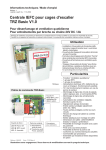
Technische Information
Technical information
und Bedienungsanleitung and operating instruction
Ausgabe: 3
Gültig ab: 30.09.2008
Version: 3
valid from: 30.09.2008
Modulare RWA Steuerzentrale Typ MZ...A-...RG-...LG
Modular SHE control panel type MZ...A-...RG-...LG
Steuerzentrale in Modulbauweise für Rauchabzug und Lüftung
Modular design control panel for smoke extraction and ventilation applications
Einsatzbereich
Rauchabzug
SMOKE VENT
B
Area of application
• Rauch- und Wärmeabzugsanlage für
elektromotorisch zu öffnende
Rauchabzugsklappen
• smoke and heat extraction system
utilizing electric motor driven smoke
extraction panels
• natürliche Rauch- und Wärmeabzugsanlage in Form von Lichtkuppeln,
Dachklappen oder Fenstern mit Linearoder Kettenantrieben 24 V DC (im folg.
Text kurz NRWG`s genannt)
• smoke extraction panels in the form of
24 V DC linear- and chain drive
equipped sky lights, roof panels or
windows (simply called “windows”
hereafter)
• Rauch- und Wärmeabzugsanlagen mit
mehreren RWA- und Lüftungsgruppen
• multiple SHE and vent groups smoke
and heat extraction systems
• Öffnen der Rauchabzugsklappen im
Brandfall
• opening of smoke panels in case of fire
• Schließen der Rauchabzugsklappen
nach Auslösung durch die RESETFunktion
• re-closing of smoke panels by activating
“RESET” function
• Öffnen und Schließen für die tägliche
Lüftung
• opening and closing panels for daily
ventilation
• mit 72 Stunden Notstromversorgung bei
Netzausfall
• providing a 72 hour emergency power
back-up during power black-out
AUART
G
EP
T
Nr.: 2737/96
RÜF
Diese Bedienungsanleitung für späteren Gebrauch bzw. Wartung aufbewahren. Please keep these operating instruction for future reference and maintance.
Änderungen dienen dem technischen Fortschritt und bleiben vorbehalten. Abbildungen unverbindlich. Subject to technical modifications. Diagram is not binding.
Datei:
Ti_MZ_allgemein_dt_engl_neutral.cdr
Art.Nr. 24999868
D
GB
Sicherheitshinweise
Safety instructions
Sicherheitshinweise, die Sie unbedingt beachten müssen,
werden durch besondere Zeichen hervorgehoben
Please observe the following safety which are emphasized
by special symbols
Vorsicht / Warnung / Achtung
Gefahr für Personen durch elektrischen Strom
Caution / Warning / Attention
Danger to persons due to electricity
Vorsicht / Warnung / Achtung
Nichtbeachtung führt zur Zerstörung Gefährdung
für Material durch falsche Handhabung
Caution / Warning / Attention
Non-observance leads to destruction
Danger to material due to incorrect handling
Vorsicht / Achtung / Warnung
Gefährdung für Personen durch Gefahren aus
dem Gerätebetrieb. Quetsch- und Klemmgefahr
Caution / Attention / Warnng
Danger to persons due to risks arising from the
operation of the equipment. Danger of crushing/trapping
INFO
INFO
Warnung 230 V AC
Gefährliche Spannung. Kann Tod, schwere Körperverletzung oder
erheblichen Sachschaden verursachen. Trennen Sie das Gerät
allpolig von der Versorgungsspannung bevor Sie es öffnen,
montieren oder den Aufbau verändern. VDE 0100 für 230 V
Netzanschluss beachten.
Warning 230 V AC
Dangerous voltage. Can cause death, serious injury or
considerable material damage. Disconnect the equipment from the
power supply at all poles before opening, assembling or carrying
out any structural alterations. Observe VDE 0100 for
230 V power connection.
Beachten Sie bei der Montage und Bedienung
Das Fenster schließt automatisch.
Beim Schließen und Öffnen stoppt der Antrieb über die
Lastabschaltung. Die entsprechende Druckkraft entnehmen Sie
bitte den technischen Daten. Die Druckkraft reicht aber auf jeden
Fall aus bei Unachtsamkeit Finger zu zerquetschen.
Bei der Montage und Bedienung nicht in den Fensterfalz und in
den laufenden Antriebl greifen!
Quetsch- und Klemmgefahr!
Please observe the following for assembly and operation
The window closes automatically.
When opening and closing, the drive unit is stopped by the power
cut-off. The corresponding pressure force is listed in the technical
data. Take care - the pressure force is high enough to crush your
fingers.
During assembly and operation, do not interfere with the window
gap or the travelling drive!
Danger of crushing/trapping!
Bedienungsanleitung
für die fachgerechte Montage, Installation und angemessene Wartung durch
den geschulten, sachkundigen und sicherheitsbewussten Elektro-Installateur
und / oder Fachpersonal mit Kenntnissen der elektrischen Geräteinstallation.
Lesen und Beachten Sie die Angaben in dieser Bedienungsanleitung und
halten Sie die vorgegebene Reihenfolge ein.
Diese Bedienungsanleitung für späteren Gebrauch / Wartung aufbewahren.
Ein zuverlässiger Betrieb und ein Vermeiden von Schäden und Gefahren ist
nur bei sorgfältiger Montage und Einstellung nach dieser Anleitung gegeben.
Bitte beachten Sie genau die Anschlussbelegung, die minimalen und
maximalen Leistungsdaten (siehe technischen Daten) und die
Installationshinweise.
Operating instructions
for professional assembly, installation and appropriate maintenance by
trained, qualified and safety-conscious electricians and/or skilled staff with
knowledge of electrical equipment installation.
Read and observe the information contained in these operating instructions
and respect the order of procedure stated therein.
Please keep these operating instructions for future reference and
maintenance. Reliable operation and the prevention of damage and risks are
only granted if the equipment is assembled carefully and the settings are
carried out according to these instructions and to the operating instructions
of the drives.
Please observe the exact terminal assignment, the minimum and maximum
power ratings (see technical data) and the installation instructions.
Anwendungsbereich
ausschließlich für automatisches Öffnen und Schließen der angegebenen
Fensterformen. Weitere Anwendungen im Werk erfragen.
Es würde den Rahmen dieser Bedienungsanleitung sprengen, alle gültigen
Bestimmungen und Richtlinien aufzulisten.
Prüfen Sie immer, ob Ihre Anlage den gültigen Bestimmungen entspricht.
Besondere Beachtung finden dabei: Öffnungsquerschnitt des Fensters,
Öffnungszeit und Öffnungsgeschwindigkeit, Temperaturbeständigkeit von
Kabel und Geräten. Benötigtes Befestigungsmaterial ist mit dem Baukörper
und der entsprechenden Belastung abzustimmen und, wenn nötig, zu
ergänzen. Ein eventuell mitgeliefertes Befestigungsmaterial entspricht nur
einem Teil der Erfordernisse.
Wartungsarbeiten
Werden die Geräte in Rauch- und Wärmeabzugsanlagen (kurz RWA)
eingesetzt, müssen sie mindestens einmal jährlich geprüft, gewartet und ggf.
instand gesetzt werden. Bei reinen Lüftungsanlagen ist dies auch zu
empfehlen.
Die Geräte von Verunreinigungen befreien. Befestigungs- und Klemmschrauben auf festen Sitz prüfen. Die Geräte durch Probelauf testen. Das
Motorgetriebe ist wartungsfrei. Defekte Geräte dürfen nur in unserem Werk
instand gesetzt werden. Es sind nur Original-Ersatzteile einzusetzen. Die
Betriebsbereitschaft ist regelmäßig zu prüfen. Ein Wartungsvertrag ist
empfehlenswert. Alle serienmäßig mit der RWA-Steuerzentrale gelieferten
Akkus bedürfen einer regelmäßigen Kontrolle im Rahmen der Wartung und
sind nach der vorgeschriebenen Betriebszeit (ca. 4 Jahre) auszutauschen.
Bei der Entsorgung der verwendeten Gefahrstoffe - z.B. Akkus - Gesetze
beachten.
2
Application range
Exclusively for the automatic opening and closing of the stated types of
windows. For further application, please contact the manufacturer.
It would be beyond the scope of these safety instructions to list all the valide
regulations and guidelines.
Always make sure that your system corresponds to the valid regulations. Pay
particular attention to: the aperture cross-section of the window, the opening
time and opening speed, the temperature resistance of the cables and
equipment, cross-sections of the cables in relation to the cable lengths and
power consumption. Required mounting material is to be adapted to the
frame and the corresponding load and is to be completed, if necessary. Any
supplied mounting material is only part of the required amount.
Maintenance works
If the equipment is employed in smoke heat extraction systems (in short
SHE), they must be checked, serviced and, if required, repaired at least
once per year. This is also recommended for pure ventilation systems.
Free the equipment from any contamination. Check the tightness of fixing
and clamping screws. Test the equipment by trial run.
The gear system is maintenance free. Defective equipment must only be
repaired in our factory. Only original spare parts are to be used.
The readiness for operation has to be checked regularly. For this purpose a
service contract is recommended. All batteries provided with the SHE control
panel need to be regularly checked as part of the maintenance programme
and have to be replaced after their specified service life (approx. 4 years).
Please observe the legal requirements when disposing of hazardous
material - e.g. batteries.
Sicherheitshinweise
Leitungsverlegung und elektrischer Anschluss nur durch
zugelassene Elektrofirma. Netzzuleitungen 230 V AC separat
bauseits absichern. Netzzuleitungen bis an die Netzklemme
ummantelt lassen.
Bei der Installation DIN- und VDE-Vorschriften beachten, VDE 0100
Errichten von Starkstromanlagen bis 1000 V, VDE 0815
Installationskabel und -leitungen, VDE 0833 Gefahrenmeldeanlagen für Brand, Einbruch und Überfall.
Kabeltypen ggf. mit den örtlichen Abnahmebehörden, Energieversorgungsunternehmen, Brandschutzbehörden oder Berufsgenossenschaften festlegen.
Alle Niederspannungsleitungen (24 V DC) getrennt von Starkstromleitungen verlegen. Flexible Leitungen dürfen nicht eingeputzt
werden. Frei hängende Leitungen mit Zugentlastung versehen. Die
Leitungen müssen so verlegt sein, dass sie im Betrieb weder
abgeschert, verdreht noch abgeknickt werden.
Abzweigdosen müssen für Wartungsarbeiten zugänglich sein.
Die Kabelarten, -längen und -querschnitte gemäß den technischen
Angaben ausführen.
Vor jeder Wartungsarbeit oder Veränderung des Aufbaus
sind die Netzspannung und Akkus allpolig abzuklemmen. Gegen unbeabsichtigtes Wiedereinschalten ist
die Anlage abzusichern. Elektrische Steuerungen
müssen stromlos sein, bevor Sie Teile entnehmen oder
dazusetzen (Netzspannung und Akkus abklemmen).
Nach der Installation und jeder Veränderung der Anlage alle
Funktionen durch Probelauf überprüfen.
Beachten Sie bei der Montage und Bedienung: Die Fenster
schließen automatisch.
Quetsch- und Scherstellen zwischen Fensterflügel und Rahmen,
Lichtkuppeln und Aufsetzkranz müssen bis zu einer Höhe von
2,5 m durch Einrichtungen gesichert sein, die bei Berührung oder
Unterbrechung durch eine Person, die Bewegung zum Stillstand
bringen (Richtlinie für kraftbetätigte Fenster, Türen und Tore der
Berufsgenossenschaften).
Achtung! Die Antriebe und Bedienstellen niemals an
230 V anschließen! Sie sind für 24 V gebaut!
Lebensgefahr!
Bei Anwendungen am Kippfenster muss eine KippfangSicherungsschere eingebaut werden. Sie verhindert Schäden, die
bei unsachgemäßer Montage und Handhabung auftreten können.
Bitte beachten: die Kippfang-Sicherungsschere muss mit dem
Öffnungshub des Antriebes abgestimmt sein. Das heißt, die
Öffnungsweite der Kippfang-Sicherungsschere muss, um eine
Blockade zu vermeiden, größer als der Antriebshub sein. Siehe
Richtlinie für kraftbetätigte Fenster, Türen und Tore.
Schützen Sie alle Aggregate dauerhaft vor Wasser und Schmutz.
Achtung: Die Antriebe nur mit Steuerungen vom gleichen
Hersteller betreiben. Bei Verwendung von Fremdfabrikaten keine Haftung, Garantie- und Serviceleistungen. Die Montage und Installation muss sachgemäß, sicherheitsbewusst und nach Angaben der
Bedienungsanleitung erfolgen. Werden Ersatzteile,
Ausbauteile oder Erweiterungen benötigt bzw.
gewünscht, ausschließlich Original-Ersatzteile
verwenden.
Herstellererklärung
Die Geräte sind gemäß der europäischen Richtlinien geprüft und
hergestellt. Eine entsprechende Herstellererklärung liegt vor. Sie
dürfen die Geräte nur dann betreiben, wenn für das Gesamtsystem
eine Konformitätserklärung vorliegt.
Safety instructions
Routing of cables and electrical connections only to be done by a
qualified electrician. Power supply leads 230 V AC to be fused
separately by the customer. Keep power supply leads sheathed
until the mains terminal.
DIN and VDE regulations to be observed for the installation: VDE
0100 Setting up of high voltage installations up to 1000 V. VDE
0815 Installation cables and wires. VDE 0833 Alarm systems for
fire, break-in and burglary.
D
GB
Cable types to be agreed with local inspection authorities, power
utilities, fire protection authority and the professional associations.
All low voltage cables (24 V DC) to be installed separately from
high voltage cables. Flexible cables must not be plastered in.
Provide tension relief for freely suspended cables. The cables must
be installed in such a way that they cannot be sheared off, twisted
or bent off during operation. Junction boxes must be accessible for
maintenance work. Adhere to the type of cables, cable lengths and
cross-sections as stated in the technical information.
The supply voltage and the batteries are to be
disconnected at all poles before maintenance work or
structural alterations. The system must be protected
against unintentional re-starting. Electrical controls must
be voltage free before extension modules are taken off
or added (disconnect mains voltage and batteries).
After installation and any changes to the system check all functions
by a trial run.
During assembly and operation, please observe: the windows may
close automatically.
Potential crushing and cutting points between the casement and
the window frame, dome lights and support frame must be secured
up to a height of 2.5 m by safety equipment, which if touched or
interrupted by a person will immediately stop the movement
(guideline for power operated windows, doors and gates of the
professional association).
Warning! Never connect the drives and call points to
230 V! They are built for 24 V!
Risk of death!
For applications: Tilt windows: A scissor-type safety catch is to be
installed. It prevents damage caused by incorrect assembly and
handling. Please observe: the scissor-type safety catch must be
adapted to the opening stroke of the drive unit, i.e. that the opening
of the safety catch must be larger than the drive unit stroke in order
to prevent blocking. See guideline for power-operated windows,
doors and gates.
Provide all aggregates with durable protection against water and
dirt!
Attention: The control must only be operated with drives
made by the same manufacturer. No liability will be
accepted and no guarantee nor service is granted if
products of outside manufacturers are used. Assembly
and installation must be carried out properly, according
to the information of the operating instructions paying
particular attention to safety aspects. If spare parts,
dismantled parts or extension components are required
or desired, only use original spare parts.
Manufacturer’s declaration
The equipment has been manufactured and tested according to
the European regulations. A corresponding manufacturer’s
declaration has been submitted. You may only operate the system
if a Declaration of Conformity exists for the entire system.
3
Funktionsbeschreibung
Description of operating
Die Steuerzentrale ist als modulare Zentrale aufgebaut.
Die maximale Anzahl der anschließbaren Antriebe und die Anzahl der
vorhandenen Gruppen ist durch die Typenbezeichnung klar definiert:
siehe Technische Daten.
The control panel is designed as a modular panel.
The maximum number of connectable drive units and the number
of available groups is clearly specified by the product designation:
see technical data.
Folgende Module sind in der Grundausführung enthalten:
• Netzmodul NM 2
Das Netzmodul dient zur Spannungsversorgung der Zentrale und
der Module, sowie zur Laderegelung der Notstromakkus und zur
Umschaltung auf Akkubetrieb bei Netzausfall.
The following modules are contained in the basic model:
• Power pack NM 2
The power pack is used for the power supply of the control panel
and the modules, as well as for charging the stand-by batteries,
also for the changeover to battery operation in case of power
failure.
• RWA-Gruppenmodul RGM 2
Jedes RWA-Gruppenmodul beinhaltet eine RWA-Gruppe und eine
Lüftungs-Gruppe. Die LED-Anzeigen zeigen folgenden Status an:
Alarm ausgelöst, Störung der Rauchmelder-Gruppe, der RWATaster-Gruppe und der Motorgruppe. Eine Resettaste für die
Rücksetzung der Rauchmelder ist vorhanden. Die Stromkreise zu
den Antrieben, den Rauchmelder-Gruppe(n) und den RWA-TasterGruppe(n) werden auf Leitungsbruch und Kurzschluss überwacht.
Alle 120 Sek. erfolgt ein Nachtakten der RWA-Antriebe bei RWAAuslösung zum Lösen evtl. vereister Fenster oder Klappen.
Geringe Stromaufnahme bei Akkubetrieb.
• SHE group module RGM 2
The number of group modules corresponds to the maximum
number of available SHE lines. One SHE line can be addressed per
group module. The LED displays indicate the following stati: Alarm
activated, malfunction of smoke detector line, SHE switch line and
motor circuit. A reset switch for the re-setting of the smoke detector
line is available. The electric circuits to the drive units, the smoke
detector line(s), and the SHE switch line(s) are permanently
monitored for cable breakage.
Folgende Komponenten sind anschließbar:
• 10 RWA-Bedienstellen mit LED-Anzeige für Betrieb, Auslösung
und Störung
• 10 automatische Melder in 2-Leiter-Technik
• 8 A Motorlast je Motorgruppe: Linear- oder Kettenantriebe
24 V DC
• 10 Lüftungstaster AUF / STOP / ZU mit oder ohne LED,
Anzeige Lüftung-Auf (24 V / max. 50 mA)
Zur Erweiterung stehen folgende Zusatzmodule zur
Verfügung
• RWA-Gruppenmodul für Haftmagnete/DruckgasGeneratoren - RGMHD
Zur Betätigung von Rauchklappen über Druckgasgeneratoren
oder über Haftmagnete.
The following components can be connected:
• 10 SHE manual call points with LED: operation, activation and
mailfunction
• 10 automatic detectors in 2-conductor-technology
• 8 A motor load per motor cluster: linear or chain drive units
24 V DC
• 10 vent switches OPEN / STOP / CLOSED, with or without LED
separate Open display (24 V / max. 50 mA)
The following additional modules are available for
extensions
• SHE group module for HF and DG RGMHD
This module is used to actuate smoke vents via pressurized gas
generator or via adhesive magnets. A reset switch for the
re-setting of the smoke detector line is available.
Folgende Komponenten sind anschließbar:
• 10 RWA-Bedienstellen bzw. Notauslösetaster mit LED-Anzeige
(die Melderlinie kann als 2-Melderabhängigkeit geschaltet
werden)
• 10 automatische Melder in 2-Leiter-Technik
• 16 Druckgasgeneratoren oder
• Haftmagnete bis max. 1 A (potenzialfrei 24 V) in einer RWAGruppe
The following components can be connected:
• 10 SHE manual call points or emergency release control
switches
• 10 automatic detectors in 2-conductor-technology
• 16 pressurized gas generators or
• 1 A adhesive magnets (p.f. 24 V/max.1 A) in one SHE grupp
• Rauch-Gruppen-Druck-Regel-Modul RGDRM
Mit diesem Modul werden Steuerzentralen für RauchschutzDruck-Anlagen (RDA-Anlagen), die mit Zuluftventilatoren arbeiten,
ausgestattet.
Die Druckregelung öffnet und schließt die RWA-Öffnung, so dass
der Überdruck im eingestellten Bereich zwischen 15 und 50 Pa
gehalten wird. In Verbindung mit Drucksensor DDS.
• Smoke group pressure control module RGDRM
This module is used in control panels for pressure differential
smoke control systems (RDA equipment), which work with fresh
air ventilators. The pressure control opens and closes the SHE
opening, so that the overpressure stays at the preset level
between 15 and 50 Pa. In conjunction with the DDS pressure
sensor.
Folgende Komponenten sind anschließbar:
• 10 RWA-Bedienstellen bzw. Notauslösetaster
• 10 Lüftungstaster AUF/STOP/ZU
• 10 automatische Melder in 2-Leiter-Technik
• 8 A Motorlast: Linear- oder Kettenantriebe 24 V DC
• 1 Drucksensor DDS, 5-20 mA (15-50 Pa)
• 1 separate Auf-Anzeige (24 V / max. 50 mA)
4
The following components can be connected:
• 10 SHE manual call points or emergency release
control switches
• 10 vent switches OPEN/STOP/CLOSED
• 10 automatic detectors in 2-conductor-technology
• 8 A motor load: linear or chain drive units 24 V DC
• 1 pressure sensor DDS, 5-20 mA (15-50 Pa)
• 1 separate Open display (24 V / max. 50 mA)
Funktionsbeschreibung
Description of operating
• Koppelmodul für RWA und Lüftung - KMRL
Dieses Modul dient zur Verschaltung mehrerer RWA-Modulzentralen zur Weiterleitung der RWA- und Lüftungs-Meldung auf
eine weitere RWA-Zentrale. Eine Kaskadierung mehrerer RWAModulzentralen ist möglich. Die Verbindungsleitungen zwischen
den Zentralen für die RWA-Auf-Funktion ist leitungsüberwacht.
• Coupling module for SHE and ventilation KMRL
The coupling module is used for wiring several SHE module
panels together to transfer the SHE and ventilation message to a
further SHE panel. Several SHE module panels can be
cascaded at the same time. The connection lines between the
panels for the SHE “open” function are line monitored.
• Lüftungs-Gruppenmodul LGM
Das Lüftungs-Gruppenmodul wird bei zusätzlich erforderlichen
Motorgruppen in einer gemeinsamen RWA-Gruppe oder als
Lüftungsgruppe ohne RWA-Funktion eingesetzt.
• Ventilation group module LGM
The ventilation group module is intended for use with
any necessary motor groups in collective SHE line or as
ventilation group not incl. SHE function.
Folgende Komponenten sind anschließbar:
• Linear- oder Kettenantriebe 24 V DC, max. Motorlast 8 A
• 10 Lüftungstaster Auf / Stop / Zu mit oder ohne LED
• 1 separate Auf-Anzeige (24 V / max. 50 mA)
• Lüftungs-Gruppenmodul LGM 230 V
Mit dem Modul LGM 230 V werden 230 V AC-Antriebe gesteuert.
Folgende Komponenten sind anschließbar:
• 10 Linear- oder Kettenantriebe 230 V AC / max. 4 A
• 1 Lüftungstaster 24 V DC AUF/ STOP/ ZU
• 1 separate Auf-Anzeige (24 V / max. 50 mA)
• Lüftungsmodul LM
Zur Ansteuerung von 24 V Antrieben zum Öffnen und Schließen mit
Lüftungstastern. Dieses Modul beinhaltet eine Lüftungsgruppe mit
einem Motorkreis. Eine Verschaltung mit weiteren Lüftungsmodulen LM erfolgt über den internen Modul-Bus.
Folgende Komponenten sind anschließbar:
• Linear- oder Kettenantriebe 24 V DC, max. Motorlast 8 A
• 10 Lüftungstaster Auf / Stop / Zu
• 1 separate Auf-Anzeige (24 V / max. 50 mA)
• Wind-Regen-Melde-Modul-Potenzialfrei WRMMP
Zur Ansteuerung von bis zu 6 Gruppenmodulen. Das Modul ist
mit einem potenzialfreiem Kontakt zur Signalweiterleitung an eine
weitere Zentrale ausgestattet.
Folgende Komponenten sind anschließbar:
• 1 Wind-/Regenmelder WRM 24 V
• 1 Regenmelder RM 24 V
• 1 Signalweiterleitung (230 V / max. 1 A)
D
GB
The following components can be connected:
• 24 V DC linear or chain drive motor units, max. 8 A motor load
• 10 vent switches “Open”/“Stop”/“Closed” with or without LED
• 1 separate display “Open” (24 V / max. 50 mA)
• Ventilation group module LGM 230 V
To control 230 V drives.
The following components can be connected:
• 10 linear or chain drives 230 V AC, max. 4 A motor load
• 10 vent switches 24 V DC “open” / “stop” / “closed”
• 1 separate display “open” (24 V / max. 50 mA)
• Ventilation module LM
To control the “Open” and “Closed” function of 24 V drive
mechanisms using the ventilation keys. This module includes
one ventilation group with a motor circuit. Wiring together with
further ventilation modules LM/ is carried out via the internal
module-bus.
The following components can be connected:
• 24 V DC linear or chain drive motor units, max. 8 A motor load
• 10 vent switches “Open”/“Stop”/“Closed”
• 1 separate display “Open” (24 V / max. 50 mA)
• Wind rain detector module potential-free WRMMP
As WRMM/ but with potential-free contact for signal transmission
to another control panel.
The following components can be connected:
• 1 wind / rain detector WRM 24 V
• 1 rain detector RM 24 V
• 1 signal transmission (230 V / max. 1 A)
• Temperatur-Regel-Modul TRM
Zum öffnen und schließen der Fenster in Abhängigkeit der
Raumtemperatur. Durch den Einsatz von 2 Thermostaten wird
eine obere und eine untere Schalttemperatur definiert.
• Temperature control module TRM
For the opening and closing of windows depending on room
temperature. The upper and lower temperature limits are
defined by using two thermostats.
• Betriebs-Alarm-Störmeldemodul BASMM
Durch dieses Modul können bis zu 3 Signale wie z. B. Netzausfall,
Sammelstörung und RWA-Auslösung durch potenzialfreie
Kontakte weitergeleitet werden. Kontaktbelastung je 30 V /
max. 1 A.
• Operation alarm malfunction signal module BASMM
This module is able to transmit up to 3 signals such as:
“power failure”, “collective malfunction” and “SHE alarm
activated” using potential-free contacts. The contact load is
30 V / max. 1 A each.
5
Funktionsbeschreibung
Description of operating
• Betriebs-Alarm-Störungs-Signal-Modul BASSM
Über dieses Modul werden optische und akustische 24 V DC
Signalgeber wie z. B. Alarmhupe und Blitzleuchte angesteuert
(Abschaltung der Signale ist nach 60 Sek. oder 180 Sek.
möglich). Die Signale RWA-Auslösung, Netzausfall und
Sammelstörung können durch potenzialfreie Schließerkontakte
weitergeleitet werden. Kontaktbelastung je 30 V / max. 1 A.
• Operation alarm malfunction signal module BASSM
This module actuates optical and acoustical 24 V DC signal
provings such as alarm horns and flashing lights (signal cut-off
after 60 sec. or 180 sec. feasible). The following signals can be
transmitted: “SHE activation”, “power failure” and “collective
malfunction” using potential-free NO-contacts. The contact load
Is 30 V / max. 1 A each.
• Meldemodul MM1K
Zur potenzialfreien Ansteuerung externer Geräte wie z. B.
Brandmeldeanlagen, Telefonwahlgeräte, GLT, ZLT usw.
Ein Wechsler (Kontaktbelastung 230 V / max. 5 A) steht zur
Verfügung.
• Alarm module MM1K
This module activates external devices such as Fire Alarm
Systems (FAS), Building Management Systems etc. potentialfree. A change over contact (contact load 230 V / max. 5 A) is
available.
• Meldemodul MM2K
Zur potenzialfreien Ansteuerung externer Geräte wie z. B.
Brandmeldeanlagen, Telefonwahlgeräte, GLT, ZLT usw.
Zwei Wechsler (Kontaktbelastung 230 V / max. 5 A) stehen zur
Verfügung.
• Alarm module MM2K
This module activates external devices such as Fire Alarm
Systems (FAS), Building Management Systems (BMS) etc.
Potential-free. Two change over contacts (contact load 230 V /
max. 5 A) are available.
• Wartungs-Informations-Modul WIM
Das Wartungsmodul signalisiert die Fälligkeit der jährlichen
Servicewartung. Das Modul löst ca. nach 1Jahr nach der letzten
Servicewartung automatisch aus. Die nötige Wartung wird
optisch angezeigt.
• Maintenance information module WIM
Approx. one year after annual maintenance, the WIM triggers an
signal for the new maintenance due date. The necessary
maintenance is displayed optically and accoustically.
• Windrichtungs-Informationsmodul WRIM
Zur Auswertung der Windrichtung eines Windrichtungsgebers
über 8 potenzialfreie Wechsler (Kontaktbelastung 30 V /
max. 1 A).
• Wind direction information module WRIM
Wind direction information module for the evaluation of wind
direction using a wind direction detector. The wind direction is
made available using 8 potential-free change over contacts
(contact load 30 V / max. 1 A).
• Wind-Richtungs-Geber WRG
Zur Richtungsmessung der horizontalen Luftströme in
Verbindung mit WRIM Modul.
Ansprechempfindlichkeit: 0,5 m / Sek.
Fahnenlänge: 150 mm
Fahnenhöhe: 100 mm
• Wind direction transmitter WRG
To determine the direction of horizontal air currents in connection
with the WRIM module.
Operating threshold sensitivity: 0.5 m / sec.
Vane length: 150 mm
Vane height: 100 mm with heating
• Motorlastrelais MLR16A
Das Motorlastrelais dient zur Verstärkung der 8 Ampere
Standard-Motorbelastung auf 16 Ampere.
• Motor load relay 16A MLR16A
The motor load relay is used for amplifying the 8 A standard
motor load to 16 A.
• Modul Gebäudeleittechnik GLT
Zur Ansteuerung von 0-10 V. Mit diesem Modul werden auf ein
Gruppen- oder Lüftungsmodul bauseits 0-10 V aufgeschaltet.
Diese Ansteuerung dient einer kontrollierten Zwischenstellung
bzw. Öffnungsweite des Fensterantriebs.
• Building Management System Module GLT
For 0-10 V motor units. For 0-10 V on-site over plugging of a
group- or ventilation module to achieve controlled intermediate
opening positions or widths of an motor unit.
• Zeitschaltuhr ZSM
Zur automatischen Ansteuerung von bis zu 6 Gruppenmodulen.
Es stehen 2 Kanäle zur Verfügung mit denen max. zweimal 6
Gruppen zu einer bestimmten Zeit geschlossen oder 6 Gruppen
zu einer bestimmten Zeit geöffnet und geschlossen werden
können.
• Timer ZSM
The timer is used to activate or ventilate automatically up to
six groups or line modules. There are two channels available
through which a max. of: 2 times 6 groups can be closed at a
particular timer or 6 groups can be opened or closed at a
particular time.
• Überwachungsmodul UEB2
Überwachungsmodul zur Aufschaltung einer bauseitigen Brandmeldeanlage (BMA) auf den Meldereingang einer Treppenraumzentrale TRZ, TRZ-Basic oder RWA-Modulzentralen MZ, MZ2.
Jede BMA-Linie benötigt ein UEB2 Modul innerhalb der BMAZentrale.
• Monitoring module UEB2
Monitoring module enabling the switching on of a customer's fire
alarm system (FAS) on receipt of the input signal of a stairwell
central control unit TRZ, TRZ-Basic or SHE modular central
control units MZ, MZ2.
Each fire alarm system line requires a UEB2 module within the
FAS central control unit.
6
Funktionsbeschreibung
• LED-Anzeigen in der RWA-Bedienstelle
rote LED-Anzeige - RWA ausgelöst
leuchtet nach RWA - Auslösung auf.
grüne LED-Anzeige - Betrieb OK
leuchtet bei ordnungsgemäßem Betrieb, erlischt bei Netz- oder
Akkuausfall.
gelbe LED-Anzeige - Störung
leuchtet, wenn eine der folgenden Störungen ansteht:
Leitungsbruch in den automatischen Melder-Gruppen, RWATaster-Gruppen und in den Motorkreisen und fehlendem oder
defektem Linienabschluss.
In diesen Fällen muss unbedingt die Störung sofort
beseitigt werden. Eine reibungslose Funktion der Anlage
ist nicht mehr gewährleistet.
Description of operating
• LED displays in the SHE manual call point
red LED display - SHE activated
Lights up after SHE activation.
green LED display- operation OK
Is lit if operation is running correctly, goes out in case of power
supply or battery failure.
yellow LED display - malfunction
Lights up in case of one of the following malfunctions: Cable
breakage in the smoke detector line(s), SHE switch line(s), motor
circuits and in case of missing or defective line termination.
D
GB
In these cases the fault must be eliminated immediately.
Trouble-free operation of the system is no longer
guaranteed.
Hand-Auslösung bei Feuer/Brand/Alarm Rauchabzug/Fenster
öffnen
Auf-Taste in einer RWA-Bedienstelle drücken
g Fenster werden völlig geöffnet,
g rote LED-Anzeigen - RWA ausgelöst - leuchten in allen RWABedienstellen.
Folgende Funktionen sind außer Betrieb: Lüftung, Wind/ Regen, Zeit
und Temperatur.
Manual activation in case of fire/smoke/
alarm Smoke extraction/open windows
Press Open switch at a SHE manual call point
g The windows are opened completely,
g red LED displays - SHE activated - light up at all
SHE manual call points.
The following functions are out of operation: ventilation, wind/ rain,
time and temperature.
Rauchabzug / Fenster schließen
Zu-Taste in einer RWA-Bedienstelle drücken
g Fenster schließen,
g rote LED-Anzeigen - RWA ausgelöst - erlöschen in
allen RWA-Bedienstellen.
Alle Funktion sind wieder in Betrieb.
Smoke extraction/close windows
Press Closed switch at a SHE manual call point
g The windows close,
g red LED displays - SHE activated - go out at all
SHE manual call points.
All functions available.
autom. Auslösung bei Feuer/Brand/Alarm
nur wenn automatische Melder vorhanden sind.
Autom. activation in case of fire/smoke/alarm
only if automatic detectors are available.
Rauchabzug / Fenster öffnen
Rauch erreicht die automatischen Melder
g Fenster werden völlig geöffnet,
g rote Anzeige im automatischen Melder leuchtet,
g rote LED-Anzeigen - RWA ausgelöst - leuchten in
allen RWA-Bedienstellen.
Folgende Funktionen sind außer Betrieb: Lüftung, Wind/Regen, Zeit
und Temperatur.
Smoke extraction/open windows
Smoke reaches the automatic detectors
g the windows are opened completely,
g red display in the automatic detector lights up,
g red LED displays - SHE activated - light up at all SHE
manual call points.
The following functions are out of operation: ventilation, wind/rain,
time and temperature.
Rauchabzug / Fenster schließen
Automatische Melder vom Rauch befreien, bei starker
Verschmutzung ersetzen. Taste RWA-Reset in der Steuerzentrale
drücken
g Fenster schließen,
g rote Anzeige im automatischen Melder erlischt,
g rote LED-Anzeigen - RWA ausgelöst - erlöschen in
allen RWA-Bedienstellen.
Alle Funktionen sind wieder in Betrieb.
Smoke extraction/close windows
Free automatic detectors from smoke by blowing out, replace in case
of heavy soiling. Press SHE switch in the control panel
g The windows close,
g red display in the automatic detector goes out,
g red LED displays -SHE activated - go out at all SHE
manual call points.
All functions are available.
Tägliches Lüften Fenster öffnen
Auf-Taste am Lüftungstaster betätigen
g Fenster werden vollständig geöffnet.
Unterbrechung des Öffnungsvorgangs ist durch kurzes Antippen
beider Tasten gemeinsam = Stop möglich.
Daily ventilation Open windows
Press Open switch at vent switch
gThe windows are opened completely.
The opening process can be interrupted by briefly pressing both
switches at the same time = Stop.
Fenster schließen
Zu-Taste am Lüftungstaster betätigen
g Fenster schließen.
Unterbrechung des Schließvorgangs ist durch kurzes Antippen
beider Tasten gemeinsam = Stop möglich.
Close windows
Press Closed switch at vent switch
g The windows close.
The closing process can be interrupted by briefly pressing both
switches at the same time = Stop.
Hinweis:
Bei Netzausfall oder bei RWA-Auslösung (Alarm) ist die
Lüftungs-, Wind/Regen-, Zeit und Temperaturfunktion
außer Betrieb (Akkuschonung).
Note:
In case of power failure or SHE activation (alarm), the
ventilation, wind/rain, time and temperature functions are
out of operation (to save battery power).
7
Muster Kabelplan
Sample Wiring Plan
Linearantriebe mit eingebauter Lastabschaltung
Linear drives with intergrated power cut-off switch
Max. Gesamtleitungslänge 50 m / max. total cable length 50 m
Letzte Abzweigdosen
mit Überwachungsdioden
last junction box with
monotoring diodes
Gruppe 1 + 2 / group 1 + 2
Gruppe 1
group 1
Motorkreis 1 (MK)
motor group (MG)
IY (ST) Y 2 x 2 x 0,8
Linearantriebe mit eingebauter Lastabschaltung
Linear drives with intergrated power cut-off switch
Wind/ Regenmelder
WRM 24 V
oder Regenmelder
RM 24 V, max. 1 Stück
wind/ rain detector WRM 24 V
or rain detector RM 24 V ,
max. 1 piece
Gruppe 2
group 2
Motorkreis 2 (MK)
motor group 2 (MG)
24 V DC / 100 mA
J-Y(ST)Y 2 x 2 x 0,8
Leitungslänge bis 150 m
J-Y(ST)Y 4 x 2 x 0,8 Leitungslänge
bis 300 m (Adern doppelt auflegen)
J-Y(ST)Y 2 x 2 x 0,8
cable length up to 150 m
J-Y(ST)Y 4 x 2 x 0,8 cable length
up to 300 m (double the cores)
siehe Kapitel Leitungslängen/ see chapter on “Cable Lengths”
Achtung:
Schutzleiterader (grün/gelb)
darf nicht verwendet werden!
VDE-Vorschriften beachten!
Netz 230 V/50 Hz
NYM-I 3 x 1,5 mm²
Separat abschaltbaren
Stromkreis vorsehen.
Vor unbeabsichtigtem
Abschalten sichern.
Caution:
VDE regulations do not
permit to use safety wire
(green/yellow) for this
application!
NYM-I 3 x 1,5mm²
ab > 48 A
NYM-I 5 x 1,5mm²
Mains 230 V/50 Hz
NYM-O 3 x 1.5 mm²
provide a separately
disconnetible circuit.
Secure against unintentinal
switching-off.
letzter autom. Melder:
(10 KΩ Widerstand)
Endwiderstand: max. 10 Stück
autom. Melder je Gruppe
last autom. smoke detector:
(10 KΩ resistor)
End resistance: max. 10 detectors
per group
IY (ST) Y 3 x 2 x 0,8
IY (ST) Y 4 x 2 x 0,8
IY (ST) Y 3 x 2 x 0,8
RWA-Bedienstelle, max. 10 Stück je Gruppe
SHE manual call point, max. 10 pieces
Max. Gesamtleitungslänge 50 m
max. total cable length 50 m
Temperatur-Sensor
Temprature sensor
Letzter RWA-Taster mit Endwiderstand
(10 KΩ Widerstand)
last SHE call point with end resistance
(10 KΩ resistor)
RWA Taste / SHE manual call point
Gruppe 1 + 2
group 1 + 2
Feuchte-Sensor
humidity sensor
Lüftungstaster Vent switch
Gruppe 1
group 1
Gruppe 2
group 2
Lüftungstaster, max. 10 Stück je Gruppe
vent switch, max. 10 pieces
Es sind die gültigen Vorgaben bzgl. einer Verkabelung mit Funktionserhalt 30 min. oder 90 min. einzuhalten. Abweichungen hierzu sind in
jedem Fall mit der Bauleitung, mit den örtlichen Abnahmebehörden, Energieversorgungsunternehmen, Brandschutzbehörden oder der
Berufsgenossenschaft abzustimmen.
Die angegebenen Leitungsquerschnitte dürfen nicht verringert werden. Sie sind für eine Umgebungstemperatur von 20 °C angegeben. Für
höhere Temperaturen, die Querschnitte erhöhen. Bei E90 (E30) müssen die Leitungsquerschnitte entsprechend den Vorschriften des Herstellers
angepasst werden.
Alle Leitungen zu der Steuerzentrale (außer Netzzuleitung) führen 24 V DC und müssen getrennt von der Netzzuleitung verlegt werden.
Bei der Leitungsverlegung sind die entsprechenden VDE-Vorschriften zu beachten.
Make sure all cable types and specifications are according to site management requirements and the appropriate national and local codes
and laws.
The stated cable cross sections must not be reduced. They are listed for an ambient temperature of 20 °C. Increase the cross sections for higher
temperatures. For E90 (E30), all cable cross sections must be adapted to the manufacturer’s specifications.
All cables to the control panel (except the mains supply lead) carry 24 V DC and must be routed separately from the mains supply lead. When
routing the cables, please observe the corresponding VDE regulations.
8
Leitungslängen und -querschnitte
cable lengths and cross sections
M
M
M
Formel zur Kabelquerschnittsberechnung
Formula to determine the necessary cable diameter
2
Kabelquerschnitt in mm
cable cross-section in mm2 =
2
oder als Nährungsformel: A in mm
or as an approx. fomula: A in mm2 =
D
GB
Kabellänge / cable lengths
Zentrale / control
I [Gesamtstromaufnahme der Antriebe] x L [Länge der Motorzuleitung in m] x 2 [hin und zurück]
I [total power consumption of the drives] x L [length of motor feed line in m] x 2 [bidirectional]
2,5 V [zugelassener Spannungsabfall] x 58 m/(W x mm²) [elektr. Leitfähigkeit Kupfer]
2,5 V [authorized voltage loss] x 58 m/(Ω x mm²) [electrical conductivity copper]
I [Gesamtstromaufnahme der Antriebe] x L [einfache Länge der Motorzuleitung in m]
I [total power consumption of motor drive] x L [length of motor cables in m]
73
Beispiel:
Berechnung des benötigten Kabelquerschnitts bei 100 m Motorzuleitung (gemessen von der RWA-Zentrale bis zum letzten Antrieb im
Motorkreis) bei 8 Antrieben mit einer Stromaufnahme von je 1 A.
Example:
Calculation of the required cable cross-section for a motor feed line of 100 m (measured from the SHE-center till the last drive in the motor
group) with 8 drives of 1 A current consumption each.
8 x 1 A x 100 m
A=
= 10,95 » ca./ approx. 11 mm²
73
Kabelquerschnitte und -längen* für RWA- und Lüftungsanlagen
Cable diameters and -lengths* for SHE and vent systems
* Maximal zulässige Kabellänge von der Steuerzentrale bis zum letzten Verteiler Fensterantrieb.
* Maximal authorized length of cable from the control panel to the last motor drive.
In Verbindung mit Antrieben bis zu einer maximalen Stromaufnahme von 0,7 Ampere
In connection with motor units up to a maximum current consumption of 0.7 Ampere
Strom
current
0,7 A
1,4 A
2,1 A
2,8 A
3,5 A
4,2 A
4,9 A
5,6 A
Anzahl Antriebe
number of motors
1
2
3
4
5
6
7
8
3 x 1,5 mm²* 5 x 1,5 mm²* 3 x 2,5 mm²* 5 x 2,5 mm²* 3 x 4 mm²*
155 m
78 m
52 m
39 m
31 m
26 m
22 m
19 m
311 m
155 m
104 m
78 m
62 m
52 m
44 m
39 m
259 m
129 m
86 m
65 m
52 m
43 m
37 m
32 m
518 m
259 m
173 m
129 m
104 m
86 m
74 m
65 m
414 m
207 m
138 m
104 m
83 m
69 m
59 m
52 m
3 x 6 mm²
621 m
311 m
207 m
155 m
124 m
104 m
89 m
78 m
3 x 10 mm²*
1036 m
518 m
345 m
259 m
207 m
173 m
148 m
129 m
In Verbindung mit Antrieben bis zu einer maximalen Stromaufnahme von 1,0 Ampere
In connection with motor units up to a maximum current consumption of 1.0 Ampere
Strom
current
1A
2A
3A
4A
5A
6A
7A
8A
Anzahl Antriebe
number of motors
1
2
3
4
5
6
7
8
3 x 1,5 mm²*
109 m
54 m
36 m
27 m
22 m
18 m
16 m
14 m
5 x 1,5 mm²* 3 x 2,5 mm²* 5 x 2,5 mm²* 3 x 4 mm²* 3 x 6 mm²
218 m
109 m
73 m
54 m
44 m
36 m
31 m
27 m
181 m
91 m
60 m
45 m
36 m
30 m
26 m
23 m
363 m
181 m
121 m
91 m
73 m
60 m
52 m
45 m
290 m
145 m
97 m
73 m
58 m
48 m
41 m
36 m
435 m
218 m
145 m
109 m
87 m
73 m
62 m
54 m
3 x 10 mm²*
725 m
363 m
242 m
181 m
145 m
121 m
104 m
91 m
9
Leitungslängen und -querschnitte
cable lengths and cross sections
In Verbindung mit Antrieben bis zu einer maximalen Stromaufnahme von 1,5 Ampere
In connection with motor units up to a maximum current consumption of 1.5 Ampere
Strom
current
1,5 A
3A
4,5 A
6A
7,5 A
Anzahl Antriebe
number of motors
1
2
3
4
5
3 x 1,5 mm²* 5 x 1,5 mm²* 3 x 2,5 mm²* 5 x 2,5 mm²* 3 x 4 mm²*
73 m
36 m
24 m
18 m
15 m
145 m
73 m
48 m
36 m
29 m
121 m
60 m
40 m
30 m
24 m
242 m
121 m
81 m
60 m
48 m
193 m
97 m
64 m
48 m
39 m
3 x 6 mm²
3 x 10 mm²*
290 m
145 m
97 m
73 m
58 m
483 m
242 m
161 m
121 m
97 m
In Verbindung mit Antrieben bis zu einer maximalen Stromaufnahme von 2,0 Ampere
In connection with motor units up to a maximum current consumption of 2.0 Ampere
Strom
current
2A
4A
6A
8A
Anzahl Antriebe
number of motors
1
2
3
4
3 x 1,5 mm²*
54 m
27 m
18 m
14 m
5 x 1,5 mm²* 3 x 2,5 mm²* 5 x 2,5 mm²* 3 x 4 mm²* 3 x 6 mm²
109 m
54 m
36 m
27 m
91 m
45 m
30 m
23 m
181 m
91 m
60 m
45 m
145 m
73 m
48 m
36 m
3 x 10 mm²*
218 m
109 m
73 m
54 m
363 m
181 m
121 m
91 m
In Verbindung mit Antrieben bis zu einer maximalen Stromaufnahme von 2,5 Ampere
In connection with motor units up to a maximum current consumption of 2.5 Ampere
Strom
current
Anzahl Antriebe
number of motors
2,5 A
5A
7,5 A
1
2
3
3 x 1,5 mm²*
44 m
22 m
15 m
5 x 1,5 mm²* 3 x 2,5 mm²* 5 x 2,5 mm²* 3 x 4 mm²* 3 x 6 mm²
87 m
44 m
29 m
73 m
36 m
24 m
145 m
73 m
48 m
116 m
58 m
39 m
3 x 10 mm²*
174 m
87 m
58 m
290 m
145 m
97 m
In Verbindung mit Antrieben bis zu einer maximalen Stromaufnahme von 3,0 Ampere
In connection with motor units up to a maximum current consumption of 3.0 Ampere
Strom
current
3A
6A
Anzahl Antriebe
number of motors
1
2
3 x 1,5 mm²*
36 m
18 m
5 x 1,5 mm²* 3 x 2,5 mm²* 5 x 2,5 mm²* 3 x 4 mm²* 3 x 6 mm²
73 m
36 m
60 m
30 m
121 m
60 m
97 m
48 m
3 x 10 mm²*
145 m
73 m
242 m
121 m
In Verbindung mit Antrieben bis zu einer maximalen Stromaufnahme von 3,5 Ampere
In connection with motor units up to a maximum current consumption of 3.5 Ampere
Strom
current
Anzahl Antriebe
number of motors
3,5 A
7A
1
2
3 x 1,5 mm²*
31 m
16 m
5 x 1,5 mm²* 3 x 2,5 mm²* 5 x 2,5 mm²* 3 x 4 mm²* 3 x 6 mm²
62 m
31 m
52 m
26 m
104 m
52 m
83 m
41 m
3 x 10 mm²*
124 m
62 m
207 m
104 m
In Verbindung mit Antrieben bis zu einer maximalen Stromaufnahme von 4,0 Ampere
In connection with motor units up to a maximum current consumption of 4.0 Ampere
Strom
current
4A
8A
Anzahl Antriebe
number of motors
1
2
3 x 1,5 mm²*
27 m
14 m
5 x 1,5 mm²* 3 x 2,5 mm²* 5 x 2,5 mm²* 3 x 4 mm²* 3 x 6 mm²
54 m
27 m
45 m
23 m
91 m
45 m
73 m
36 m
3 x 10 mm²*
109 m
54 m
181 m
91 m
In Verbindung mit Antrieben bis zu einer maximalen Stromaufnahme von 5,0 und 7,0 Ampere
In connection with motor units up to a maximum current consumption of 5.0 and 7.0 Ampere
Strom
current
5A
7A
Anzahl Antriebe
number of motors
1
1
3 x 1,5 mm²*
22 m
16 m
5 x 1,5 mm²* 3 x 2,5 mm²* 5 x 2,5 mm²* 3 x 4 mm²* 3 x 6 mm²
44 m
31 m
36 m
26 m
73 m
52 m
58 m
41 m
3 x 10 mm²*
87 m
62 m
* Ohne PE-Leiter, bei RWA-Anlagen wird die 3. Ader zu Überwachungszwecken benötigt. Laut VDE-Vorschriften darf hierfür der PE-Schutzleiter nicht verwendet werden.
* Without PE-conductor, for SHE units is a 3. Core for monotoring necessary. Officinal of the VDE the PE-conductor may not be used.
10
145 m
104 m
Cable lengths and cross sections
at pressurized gas geerators
Leitungslängen und -querschnitte
bei Druckgasgeneratoren
Anzahl der Druckgasgeneratoren pro Modul
Querschnitt
Installationskabel
3 x 1,5 mm²
3 x 2,5 mm²
3 x 1,5 mm²
3 x 2,5 mm²
1
3 x 1,5 mm²
3 x 2,5 mm²
3 x 1,5 mm²
3 x 2,5 mm²
3
4
5
6
7
700
1200
650
1120
600
1040
15
16
250
480
200
400
900
1520
850
1440
800
1360
750
1280
9
10
11
12
13
550
960
500
880
450
800
400
720
350
640
950
1600
14
300
560
8
D
GB
Maximale Länge
in Meter (m)
Number of pressurized gas generators per module
Cross section
Installation cable
2
1
2
3
4
5
950
1600
900
1520
9
550
960
6
7
8
850
1440
800
1360
750
1280
700
1200
650
1120
600
1040
10
11
12
13
14
15
16
500
880
450
800
400
720
350
640
300
560
250
480
200
400
Maximum length
in metres (m)
Die Klemmstellen in der Steuerzentrale sind für maximale Leitungsquerschnitte bis 2,5 mm² ausgelegt. Werden größere Querschnitte
verwendet, so ist eine Querschnittreduzierung unmittelbar vor der Steuerzentrale durchzuführen.
The terminal points in the control panel are designed for maximum cable cross sections up to 2.5 mm². If larger cross sections are used,
a cross section reduction is to be carried out right in front of the control panel.
Wichtiger Hinweis:
Für die Auf-Putz-Verlegung empfehlen wir Brandschutzleitungen mit Funktionserhalt E90 (E30) nach DIN 4102.
Die Querschnitte sind in jedem Fall einzuhalten. Bei Nichtbeachtung kann keine Garantie übernommen werden.
Please note:
For surface (on-wall) laying of cables, we recommend E90 rated cables (DIN 4102).
However, correct cable diameters are a must. You will forfeit any warranties in case of non-compliance.
Montage
Assembly
Die Sicherheitshinweise auf Seite 2 müssen beachtet werden.
The safety instructions on page 2 must be observed.
Elektrischer Anschluss
nur durch den geschulten, sachkundigen und sicherheitsbewussten
Elektroinstallateur. Ein zuverlässiger Betrieb und ein Vermeiden von
Schäden und Gefahren ist nur bei sorgfältiger Montage und Einstellung nach dieser Anleitung gegeben. Bitte beachten Sie genau die
Anschlussbelegung des Klemmplanes, die minimalen und maximalen
Leistungsdaten (siehe technischen Daten) und die Installationshinweise. Falsches Einklemmen und Nummern- oder Farbendreher
können zu Fehlfunktionen der Steuerzentrale oder der externen Komponenten führen. Beachten Sie das Auflegen der Abschlusswiderstände in den RWA-Taster-Gruppen und in den automatischen
Melder-Gruppen bzw. des Linienabschlusses in Form zweier Überwachungsdioden in den Motorkreisen. Nach der komplette Installation
schließen Sie die Notstromakkus und die Netzversorgung an.
Überprüfen sie zum Abschluss und bei jeder Änderung alle Funktionen, Statusanzeigen der Steuerzentrale sowie den Schwenkbereich der Antriebe.
Electrical connection
only by a trained, qualified and safety-conscious electrician.
Reliable operation and the prevention of damages and of risks is only
guaranteed, if the assembly and setting-up processes are carried out
carefully according to these instructions.
Exactly observe the terminal assignment in the wiring diagram, the
minimum and maximum power ratings (see technical data) and the
installation instructions. Incorrect installation and the mixing-up of
figures or colours can lead to malfunctions in the control panel or the
external components. Observe the installation of the terminating
resistors in the SHE switch lines and in the smoke detector lines or the
line termination in the form of two monitoring diodes in the motor
circuits. After the complete installation process, connect the stand-by
batteries and the mains supply.
Check all functions, status displays of the control panel as well as
the pivot range of the drive units on completion or after any
changes.
11
Assembly
Montage
Montage der Steuerzentrale
Beachten Sie bei der Platzierung der Steuerzentrale die Vorgaben der
Brandschutzbehörde und der Landesbauordnung. Montieren Sie die
Steuerzentrale mit geeigneten Schrauben und Dübeln an der Wand.
Assembly of the control panel
When positioning the control panel, observe the specifications of
the fire protection authority and the regional building regulations.
Mount the control panel on the wall using suitable screws and
dowels.
Montage der RWA-Bedienstellen Montage der Notauslösetaster
Beachten Sie bei der Platzierung der Taster die Vorgaben der
Brandschutzbehörde und der Landesbauordnung.
Montagehöhe der RWA-Bedienstellen 1,4 m über dem Fußboden.
Montieren Sie die RWA-Bedienstellen mit geeigneten Schrauben und
Dübeln. Als Linienabschluss den Endwiderstand 10 kOhm in der
letzten oder einzigen RWA-Bedienstelle einklemmen.
Assembly of the SHE manual call points
Assembly of the emergency release control switches
When positioning the switches, observe the specifications of the
fire protection authority and the regional building regulations.
Assembly height for the SHE manual call points 1.4 m above the
floor. Mount the SHE manual call points using suitable screws and
dowels. For line termination, install the end resistor 10 kOhm in the
last or only SHE manual call point.
Montage der automatischen Melder
Beachten Sie bei der Platzierung der Melder die entspr. Vorschriften.
Montagehöhe und Überwachungsfläche entsprechend dem
eingesetzten Meldertyps.
Als Linienabschluss den Endwiderstand 10 kOhm zwischen 1 und 3
im letzten oder einzigen Melder einklemmen. Werden keine Melder
angeschlossen, so ist der Endwiderstand direkt an den
Melderausgang des jeweiligen Moduls anzuschließen.
Assembly of the automatic detectors
When positioning the detectors, observe the corresponding
regulations. Mounting height and monitoring area according to the
type of detector used. If no smoke detectors are connected, the
final resistor needs to be connected directly to the smoke detector
outlet of the appropriate module.
Montage der automatischen Melder
Beachten Sie bei der Platzierung der Melder die entsprechenden.
Vorschriften. Montagehöhe und Überwachungsfläche entsprechend
dem eingesetzten Meldertyps.
Assembly of the drive units
According to the enclosed assembly and operating instructions.
Pay attention that the junction boxes are positioned in such a way
that the connecting cables of the drive units can be connected up
directly without extension.
Montage
Für alle weiteren Komponenten sind deren beiliegenden
Bedienungsanleitungen zu beachten.
Assembly
For all further components observe their enclosed operating
instructions.
Initial start up
Inbetriebnahme
Ohne Netzspannung, ohne Akku
Alle Teile mechanisch und elektrisch auf feste Verschraubung und auf
Beschädigungen prüfen.
Alle Klemmen: Antriebe und Bedienelemente aufstecken.
Without mains voltage, without batt
Check all parts mechanically and electrically for fully tightened
screw connections and damage.
All terminals: Drive units and control elements.
Jumpereinstellung
In allen Modulen die Jumpereinstellungen kontrollieren.
Jumper setting
Check the jumper settings in all modules.
Mit Netzspannung, mit Akku
Netzklemme aufstecken " die Antriebe dürfen nicht fahren.
Akku-Stecker aufstecken " auf richtige Polung achten.
Achtung: Verpolung führt zur Zerstörung!
With mains voltage, with battery
Plug in mains terminal " the drive units should not run.
Plug in battery connector " ensure correct polarity
Attention: Incorrect polarity leads to destruction!
Sichtanzeigen der Module kontrollieren:
Netzmodul
grüne LED - Netzbetrieb
- leuchtet
gelbe LED - Störung
- leuchtet nicht
Check visual displays of the modules:
Power pack
green LED - mains operation - lit up
yellow LED - malfunction
- not lit up
RWA-Gruppenmodul
vier LED`s
- leuchten nicht
SHE group module
four LEDs
- not lit up
Lüftungs-Gruppenmodul
zwei LED`s
- leuchten nicht
Ventilation group module
two LEDs
- not lit up
Wind-Regen-Melde-Modul
grüne LED - Betrieb
zwei gelbe LED - Signal
- leuchtet
- leuchten nicht
Wind/rain detector module
green LED - operation
two yellow LEDs - Signal
- lit up
- not lit up
Betriebs-Alarm-Störmeldemodul
grüne LED - Betrieb
- leuchtet
gelbe + rote LED
- leuchten nicht
Operating alarm malfunction module
green LED - operation
- lit up
yellow + red LEDs
- not lit up
BMA-Modul
grüne LED - Betrieb
gelbe + rote LED
FAS module
green LED - operation
yellow + red LEDs
12
- leuchtet
- leuchten nicht
- lit up
- lit up
Inbetriebnahme
Assembly
Fehlerbehebung
grüne LED - Netzbetrieb - leuchtet nicht:
Netz- und/oder Akkuanschluss und Sicherungen überprüfen.
Troubleshooting
green LED - mains operation - not lit up:
Check mains and/or battery connection and fuses.
grüne LED - Betrieb - leuchtet nicht:
Entsprechendes Modul außer Funktion " Anschluss überprüfen.
green LED - operation - not lit up:
Corresp. module out of order " check connection.
gelbe LED - Störung - leuchtet:
Leitungsabriss " Leitungsanschlüsse und entsprechende
Sicherungen prüfen.
Linienabschluss oder Überwachungsdioden fehlen
RWA-Auslösung wurde deaktiviert
yellow LED - malfunction - lit up:
Cable breakage " check cable connections and corresp. fuses.
Line termination or monitoring diodes are missing.
SHE trigger was deactivated.
rote LED - RWA ausgelöst - leuchtet:
Taste RWA-RESET in der Steuerzentrale drücken.
red LED - SHE activated - lit up:
Press SHE RESET switch in the control panel.
Funktionstest
Den Funktionstest bzw. Probelauf erst beginnen, wenn die StatusLED`s in Ordnung sind. Es darf weder eine Störung anstehen noch
RWA ausgelöst sein.
Functional test
Only begin the functional test or trial run, if the status LEDs are in
working order. There must be no malfunction pending and no SHE
activated.
Die folgende Reihenfolge ist einzuhalten.
Der Funktionstest ist für eine Gruppe beschrieben, für weitere
Gruppen ist ebenso zu verfahren.
Jede Gruppe ist einzeln zu prüfen.
The following order is to be adhered to.
The functional test is described for one group, for further groups
proceed in the same manner.
Test each group individually.
Treten Fehlfunktionen auf, so sind diese sofort zu beheben.
If malfunctions occur, eliminate them immediately.
Funktionskontrolle und Probelauf
Lüftungstaster
Taste AUF kurz betätigen,
" Die Antriebe öffnen die Fenster vollständig bis zur Endstellung,
während dieses Laufens die Fenster genau beobachten.
Achtung: Auf Kollision der Antriebe mit dem Baukörper
achten. Antriebe dürfen in keiner Lage durch den
Baukörper behindert werden.
Anschlussleitungen der Antriebe prüfen: sie dürfen weder
auf Zug noch auf Quetschung belastet werden.
Lüftungstaster ZU kurz betätigen
" Die Antriebe schließen das Fenster,
während des Laufens STOP drücken
(STOP = beide Tasten gemeinsam drücken).
" Die Antriebe stoppen.
Lüftungstaster ZU nochmals betätigen,
" die Antriebe schließen die Fenster vollständig bis zur Endstellung.
Achtung: Auch während dieser Bewegung auf Kollision,
Zug und Quetschung achten.
D
GB
Functional check and Trail run
Vent switch
Press OPEN switch briefly.
" The drive units open the windows completely up to the limit
position, during this process observe the windows exactly.
Attention : Make sure the drives can move freely at any
time without obstructions.
Check the connecting cables of the drive units: they must
Not be strained by tension or crushing.
Press vent switch CLOSED briefly
" The drive units close the window,
press STOP during running
(STOP = press both switches at the same time)
" the drive units stop.
Press vent switch CLOSED again,
" the drive units close the windows completely up
to end position.
Attention: Also watch for collision, tension and crushing
during this movement
RWA-Bedienstelle
Taste RWA-AUF kurz betätigen
" Die Fenster öffnen vollständig.
" Die rote LED-Anzeige - RWA ausgelöst -leuchtet.
" Die grüne Anzeige - Betrieb OK - leuchtet.
SHE manual call point
Press SHE-OPEN briefly
" The windows open completely.
" Red LED display - SHE activated -lit up.
" Green display - operation OK - lit up.
" Die grüne Anzeige leuchtet nicht:
Es steht eine Störung an, sofort beheben.
Taste ZU im Lüftungstaster drücken,
" keine Reaktion der Anlage.
" The green display not lit up:
A malfunction has occurred, eliminate immediately.
Press CLOSED switch in vent switch,
" no system reaction.
13
Funktionskontrolleund
und Probelauf
Probelauf
Funktionskontrolle
Functional check and Trail run
RESET-Taste in der RWA-Bedienstelle drücken
" Die Fenster schließen vollständig.
" Die rote LED-Anzeige - RWA ausgelöst - erlischt.
" Die grüne Anzeige - Betrieb OK - leuchtet.
Taste RWA-AUF kurz betätigen
" Die Fenster öffnen.
Während des Laufes Taste AUF und ZU im Lüftungstaster
gemeinsam drücken.
" Keine Reaktion der Fenster, sie dürfen nicht stoppen.
Taste RWA-RESET in der Zentrale drücken
" Die Fenster schließen vollständig.
Press RESET switch at the SHE manual call point
" The windows close completely.
" Red LED display - SHE activated - goes out.
" Green display - operation OK - lit up.
Press SHE-OPEN display briefly
" The windows open.
During running press both keys OPEN and CLOSED in the vent
switch at the same time.
" No reaction from the windows, they must not stop.
Press SHE RESET in the control panel
" The windows close completely.
Alle weiteren RWA-Bedienstellen ebenso prüfen.
Check all other SHE manual call points in the same manner.
Test automatische Melder
Autom. Melder mit Prüfaerosol ansprühen
" Die rote LED - im autom. Melder - leuchtet
" Die rote LED - RWA ausgelöst - leuchtet
" Die grüne LED - Betrieb OK - leuchtet
" Die Fenster öffnen vollständig.
Taste ZU im Lüftungstaster drücken
" Keine Reaktion der Anlage.
Taste RWA-RESET in der RWA-Bedienstelle drücken
" Die Fenster schließen vollständig.
Test automatic detectors
Spray autom. Detector with test spray
" Red LED - in autom. detector - lit up
" Red LED - SHE activated - lit up
" Green LED - operation OK - lit up
" The windows open completely.
Press CLOSED switch in the vent switch
" No system reaction.
Press SHE RESET switch at the SHE manual call point
" The windows close completely.
Test Wind/Regenmelder oder Regenmelder
Taste AUF im Lüftungstaster betätigen
" Die Fenster öffnen vollständig.
Regenfläche am Regenmelder mit Wasser benetzen
" Die Fenster schließen vollständig.
Regenfläche trocknen.
Taste AUF im Lüftungstaster betätigen
" Die Fenster öffnen vollständig.
Den Windmelder mit Wind (z.B.: Haartrockner) beaufschlagen.
" Die Fenster schließen vollständig.
Test wind/rain detector or rain detector
Press OPEN switch in the vent switch
" The windows open completely.
Moisten the rain sensor surface with water
" The windows close completely.
Dry the rain sensor surface.
Press OPEN switch in the vent switch
" The windows open completely.
Activate the wind detector with wind (e.g.: hair dryer).
" The windows close completely.
Test Notstrom
Netzsicherung in der Zentrale entfernen
" Die grüne LED - Betrieb OK - erlischt
" Die gelbe LED - Störung- leuchtet
Taste AUF im Lüftungstaster drücken.
" Keine Reaktion der Anlage.
Taste RWA-AUF kurz betätigen
" Die Fenster öffnen.
" Die rote LED - RWA-Auslösung - leuchtet
" Die grüne LED - Betrieb OK - leuchtet nicht
RESET-Taste in der RWA-Bedienstelle betätigen
" Die Fenster schließen vollständig.
" Die rote LED - RWA-Auslösung - erlischt
" Die gelbe LED - Störung - leuchtet
Netzsicherung wieder einsetzen
" Die grüne LED - Betrieb OK - leuchtet
" Die gelbe LED - Störung - erlischt.
Test stand-by power supply
Remove mains fuse in the control panel
" Green LED - operation OK - goes out
" Yellow LED - malfunction - lit up
Press OPEN switch in the vent switch.
" No system reaction
Press SHE-OPEN switch briefly
" The windows open.
" Red LED - SHE-activation - lit up
" Green LED - operation OK - not lit up
Press RESET switch at the SHE manual call point
" The windows close completely.
" Red LED - SHE activation - goes out
" Yellow LED - malfunction - lit up
Re-insert mains fuse
" Green LED - operation OK - lit up
" Yellow LED - malfunction - not lit up.
Abschließende Arbeiten
Einschlagscheiben in allen RWA-Bedienstellen einsetzen
Tür der Steuerzentrale schließen
Tel. Nr. des Störungsdienstes aufkleben.
Completion work
Install the glass panes in all SHE manual call points
Close the control panel door
Stick the telephone number of the service department on.
Hinweis: Sind weitere Bedienelemente angeschlossen
bzw. Installiert, so ist nach deren Bedienungsanleitung
vorzugehen.
Wenn der Probelauf fehlschlägt, Inbetriebnahme
wiederholen!
14
Note: Use the appropriate users manuals for any
additional modules/parts connected to the MZ control
panel. If the trial run fails, repeat initial start up
procedure!
Funktionskontrolle
und Probelauf
Fehlersuche
Trouble Shooting
Anzeige - Betrieb OK - leuchtet nicht
in den RWA-Bedienstellen und auf dem Netzmodul
• Netzanschluss nicht in Ordnung
à Netzsicherung prüfen
à Netzzuleitung / Netzspannung überprüfen
à Elektronik defekt, Gerät zur Reparatur einschicken
• Gruppenmudul nicht in Ordnung
à Elektronik defekt, siehe Beschreibung RGM
Display - operation OK - not lit up
at the SHE manual call points and at the power pack
• Power connection out of order
à Check mains fuse
à Check mains supply lead / mains voltage
à Electronics defective, send device in for repair
• Group module malfunctioning
à Electronic defect, see description RGM
Lüftungstaster mit umgekehrter Funktion
• gedrehter Anschluss am Lüftungstaster oder in der Steuerzentrale.
Vent switch with reversed function
• reversed connection at the vent switch or in the control panel.
Der Rauchabzug öffnet ohne Taster-Betätigung
• RWA-Bedienstelle falsch angeschlossen oder defekt
à prüfen und berichtigen
• autom. Melder verschmutzt
à Melder bitte tauschen
• falscher Endwiderstandswert (10K)
The smoke extraction opens without the switch being pressed
• Incorrect connection of SHE manual call point or defective
à check and correct
• Autom. detector soiled
à replace
• incorrect final resistor (10K)
Lüftungstaster ohne Funktion
• Lüftungstaster falsch angeschlossen
• RWA- Auslösung war erfolgt
à RESET-Taste in der Steuerzentrale drücken
• Netzzuleitung ohne Spannung
à instandsetzen
• Netzsicherung defekt
à Netzsicherung tauschen
• Motorsicherung defekt
à Sicherung tauschen
• Akkusicherung defekt
à Sicherung tauschen
• Wind- oder Regenmelder hat ausgelöst
Vent switch without function
• Vent switch incorrectly connected
• SHE activation had taken place
à Press RESET switch in the control panel
• Mains supply lead has no voltage
à repair
• Mains fuse defective
à replace
• Motor fuse defective
à replace
• Battery fuse defective
à replace
• Wind/rain detector alarm
Funktionskontrolle
und Probelauf
Wartung
Wartung
Maintenance
Werden die Geräte in Rauch- und Wärmeabzugsanlagen (kurz RWA)
eingesetzt, müssen sie mindestens einmal jährlich geprüft, gewartet
und gegebenenfalls instandgesetzt werden.
If the equipment is employed in smoke/heat extraction systems
(SHE systems), it must be checked, serviced and, if required,
repaired at least once a year.
Bei reinen Lüftungsanlagen ist dies auch zu empfehlen. Die Geräte
von Verunreinigungen befreien. Befestigungs- und Klemmschrauben
auf festen Sitz prüfen. Die Geräte durch Probelauf testen. Die
Antriebe sind wartungsfrei. Defekte Geräte dürfen nur in unserem
Werk instandgesetzt werden. Es sind nur Originalersatzteile
einzusetzen. Die Betriebsbereitschaft ist regelmäßig zu prüfen.
Empfehlenswert ist hierfür ein Wartungsvertrag mit dem Hersteller
oder einem autorisierten Fachbetrieb. Alle serienmäßig mit der RWASteuerzentrale gelieferten AKKUS bedürfen einer regelmäßigen
Kontrolle im Rahmen der Wartung und sind nach der
vorgeschriebenen Betriebszeit (4 Jahre) auszutauschen. Bei der
Entsorgung der verwendeten Gefahrstoffe - z.B. Akkus - Gesetze
beachten.
This is also recommended for pure ventilation systems.
Free the equipment from any contamination. Check the tightness of
fixing and locking screws. Test the equipment by trial run.
The gear systems of the spindle drive units are maintenance-free.
Defective equipment must only be repaired in our factory. Only
original spare parts are to be used. The readiness for operation is
to be checked regularly. A service contract with the manufacturer or
another authorised company is recommended for this purpose.
All batteries provided with the SHE control panel as standard
require regular testing in the course of the maintenance schedule
and are to be replaced after the specified period (approx. 4 years).
Observe the legal regulations regarding the disposal of hazardous
goods e.g. Batteries.
Funktionskontrolle
und Probelauf
Notstrombetrieb
Wartung
D
GB
Emergency power back-up operation
Ein Notstrombetrieb von 72 Stunden über die mit gelieferten Akkus
ist gewährleistet, wenn:
• Orignal Akkus seitens des Herstellers eingesetzt werden
• diese ausreichend lange geladen wurden
• keine Tiefentladung statt gefunden hat, z.B. durch Ausfall der
Netzversorgung über mehrere Tage
• keine bauliche Änderungen an der RWA-Zentrale durchgeführt
worden (z.B. Erweiterung durch zusätzliche Module)
• die Kapazität der Akkus nicht verringert wurden
An emergency power back-up operation for 72 hrs with the
provided rechargeable battery pack is guaranteed, if:
• the original manufacturer provided packs are used
• the packs were charged over a sufficient period of time
• no total discharge (deep discharge) of the packs ever took place,
for ex. due to a black-out of the main power supply over several
days
• the original control panel was not subjected to any technical
alterations (for ex. modules were added)
• the battery packs' original capacity was reduced
Ein Notstrombetrieb ist mit einer verringerten Stromaufnahme der
Module bei Netzausfall 230 V AC gewährleistet, wenn:
• die Anlage sich im Ruhezustand befand (inaktiv)
• die Lüftungsfunktionen inkl. Wind-/Regenmeldung aktiv waren
Emergency operation, with reduced power consumption of the
modules, during a 230 V main power failure is ensured when:
• the complete system was in-active
• ventilation functions, incl. wind/rain function were active
Ein Notstrombetrieb der Module ist nicht gewährleistet, wenn:
• RWA Auslösung aktiv ist
• RWA Zu aktiv ist
• RWA Reset aktiv ist
Emergency operation of the modules is not ensured when:
- SHE trigger function is active
- SHE CLOSE is active
- SHE RESET is active
15
Funktionskontrolle
und Probelauf
Klemmplan (Beispiel)
blau
braun
Anschlussdose
ein RWA-Bedienstelle
bzw. Notauslösetaster
RBH/3A
ein automatischer
Melder als Rauchoder Wärmemelder
in 2-Leiter-Technik
ein Lüftungstaster
mit Sichtanzeige
LTA 25
AUF
KONTR.
Störung
**
Endwiderstand
STOP
4
8
5
ZU
ZU
AUF
1 2
3
3
6
2
1
1
2
3
12
13
14
15
Blue
Brown
Junction
box
*
resistance 10 kOhm between
terminal 1 and 3 in the last
or only automatic detector
One SHE manual call
point or emergency release
control switch RBH/3A
one automatic
detector as a smoke
or heat detector in 2conductor-technology
**
End resistance
One vent switch
with visual display
LTA 25
OPEN CONTR.
Malfunction
STOP
1 2
3
4
+
8
OPEN
CLOSED
5
3
6
2
1
1
2
3
***
BUS
Observe the jumper
setting on the back
of the switch!
1 2 A
S
WRMMP
+ + 24 V
- - GND
Activation 6
Malfunction 7
Vent OPEN
Operation 8
Vent CLOSED
OPEN 9
SHE OPEN
CLOSED 10
SHE CLOSED
GND 11
W/R CLOSED
Temp. OPEN
No.
OPEN
12
Coll. malf.
Vent.CLOSED 13
+15 V
Vent.
OPEN
14
Emergency mode
24 V 15
General Reset
4
SHE group module 2
16
17
18
19
20
21
22
23
24
25
+24 V Group 1
+24 V Group 2
+24 V Group3
+24 V Group 4
+24 V Group 5
+24 V Group 6
Emergency mode
15 V Malfunction
1
2
3
4
5
6
7
8
Akku-Temp.-Sensor
- Detector 4
+ Detector 5
Motor A1
Motor A2
Monitoring
1
2
3
PE
Battery
Battery
Ext. capa
Ext. capa
+
+
+
B1
-
16
Power pack NM 2
A Ö
1 2 3
+ + 24 V
- - GND
19 V AC
19 V AC
27.5 V AC
27.5 V AC
T1
S
Wind / rain detector
WRM-24 V
CLOSED
ER
230 V
1 2
OPEN
ER
base USB
for
SSD + UTD
N
Notbetrieb
W/R-ZU
Handbetrieb
Lüftung ZU
GND
Line termination: Install end
resistance 10 kOhm between
terminal 1 and 3 in the last or
only SHE manual call point or
emergency release control switch
Ö
S
A
24 V
=
rain dectector
RM-24 V
***
**
Line termination: Install end
1
2
3
Drive unit 24 V with
power cut-off
F7
4
5
6
7
8
16
17
18
19
20
21
22
23
24
25
Modul-BUS
*
19 V
+ + 24 V
- - GND
Lüft. AUF
Lüft. ZU
RWA AUF
RWA ZU
W/R ZU
Temp. AUF
Sammelstör
+15 V
Notbetrieb
General Reset
+ + 24 V
- - GND
+24 V Gruppe 1
+24 V Gruppe 2
+24 V Gruppe 3
+24 V Gruppe 4
+24 V Gruppe 5
+24 V Gruppe 6
Notbetrieb
+15 V Störung
Akku-Temp.-Sensor
Ö
+ Detector
Emergency mode
- Detector
Wind/rain CLOSED
Signal
Manual operation
Ventilation CLOSED
NC contact
GND
NO contact
COM
-
Line termination: Install
2 monitoring diodes
in the last or only
junction box
L1
Ö
+
4
5
6
7
8
B1
RGM 2
LED 1
ZU 2
AUF 3
GEM 4
N
1
2
3
4
5
6
7
8
PE
- Batterie
+ Batterie
- ext. Kapa
+ ext. Kapa
F7
27.5 V
S
WRMMP
230 V
L1
1 2 A
+ Melder
- Melder
Signal
Anz. AUF
Lüft. ZU
Lüft. AUF
24 V
4
5
- Melder
+ Melder
Auslösung 6
Störung 7
Betrieb 8
AUF 9
ZU 10
- GND 11
1
2
3
T1
Jumpereinstellung
der Rückseite des
Tasters beachten !
***
Motor A1
Motor A2
Überwach.
19 V AC
19 V AC
27,5 V AC
27,5 V AC
Netzmodul NM 2
1 2 3
Wind- / Regenmelder
WRM-24 V
4
EW
19 V
A Ö
AUF
Sockel USB
für
SSD + UTD
27,5 V
S
üW
EW
*
1 2
Ö
Öffner
Schließer S
A
COM
24 V
=
Regenmelder
RM-24 V
***
Linienabschluss: Endwiderstand
10kOhm zwischen Klemme 1 und
3 in der letzten oder einzigen
RWA-Bedienstelle bzw. Notauslösetaster einklemmen
1
2
3
Antrieb 24 V mit
Lastabschaltung
**
Linienabschluss:
Endwiderstand 10kOhm zwischen
Klemme 1 und 3 im
letzten oder einzigen
automatischen Melder
einklemmen
LED 1
ZU 2
AUF 3
GEM 4
*
Linienabschluss:
2 Überwachungsdioden
in der letzten oder
einzigen Anschlussdose
einsetzen.
Connecting diagram (example)
Funktionskontrolle
und Probelauf
Klemmplan (Beispiel)
Letzter Antriebe
Anschlussdose
*
blau
mehrere RWA-Bedien- mehrere Lüftungstaster LTA 25
stellen bzw. Notausmit Sichtanzeige
lösetaster RBH/3A
**
Endwiderstand
blau
Motor
=
braun
4 8
6 2 1
1
2
3
4
1
2
3
4
D
GB
***
4 8
1 2
3
12
3
EW
1 2 3
Motor
=
braun
5
EW
Sockel USB
*** Linienabschluss:
Endwiderstand
10 kOhm zwischen
Klemme 1 und 3
in der letzten oder
einzigen RWA-Bedienstelle bzw.
Notauslösetaster
einklemmen.
**** bauseitiger Impulskontakt
der Brandmeldeanlage (BMA).
Kontakt geöffnet = keine Auslösung,
Kontakt geschlossen =
Auslösung, Impulsdauer ca. 2 sec.
mehrere autom.
Melder Typ Melder
SSD 521 oder
Melder UTD 521
mehrere Antriebe
gesamt max. 8 A
Stromaufnahme
3
5
67 8
3
9
6 2 1
10 11
12 13 14 15
1 2
3
+
ein automatischer
Melder Typ Melder
SSD 521 oder
Melder UTD 521
Ein Antriebe
gesamt max. 8 A
Stromaufnahme
oder
* Linienabschluss:
2 Überwachungsdioden
in der letzten oder
einzigen Anschlussdose
einsetzen.
** Linienabschluss:
Endwiderstand 10 kOhm
zwischen Klemme 1 und 3
im letzten oder einzigen
automatischen Melder
einklemmen.
Assembly
pot.-freier Schließerkontakt der baus.
Brandmeldeanlage
eine RWA-Bedienstellen bzw. Notauslösetaster RBH/3 A
OPEN Operation OK
Malfunction
ein Lüftungstaster LTA25
mit Sichtanzeige
OPEN
STOP
Anschlussdose
braun
Motor
=
blau
BMA Kontakt****
**
Endwiderstand
CLOSED
Open
4 8
EW
5
3
6 2 1
CLOSED
1
2
3
4
3 4
EW
*
1k
1 2 3
***
BMA
10k
+
1 2
UEB2
4
5
12
3
RWA Gruppenmodul
45
6 7 8
9 10 11
12 13 14 15
Steckbare Anschlussklemmen in der Steuerzentrale
Last drive unit
Junction
box
Brown
Motor
=
Blue
several SHE manual
call points or emergency release control
switches RBH/3 A
**
End resistance
4 8
5
3
ER
1
2
3
4
1
2
3
4
***
1 2 3
Motor
=
Blue
1 2
3
12
6 2 1
several vent
switches LTA25
with visual display
ER
*
Brown
*** Line termination: Install end
resistance 10 kOhm between
terminal 1 and 3 in the last
or only SHE manual call point
or emergency release
control switch.
several autom. detectors
as smoke or heat
detectors in
2-conductor-technology
3
4 8
base USB
** Line termination: Install end
resistance 10 kOhm between
terminal 1 and 3 in the last
or only automatic detector.
several drive units
with power cut-off
total power
consumption max. 8 A
5
67 8
3
9
6 2 1
10 11
12 13 14 15
1 2
3
**** On-site impulse contact of the FAS.
Contact Open = no activation
Contact Closed = length of activation
impulse approx. 2 sec.
+
4 5
One drive unit with
power cut-off
total power
consumption max. 8 A
Junction
box
Brown
Motor
=
Blue
one autom. detector
as smoke or heat
detector in
2-conductortechnology
or
* Line termination:
Install 2 monitoring diodes
in the last or only
junction box.
Pot.-free closer
contact of on-site of
fire alarm system
(FAS)
OPEN Operation OK
Malfunction
OPEN
STOP
**
End resistance
FAS Contact****
Open
4 8
ER
*
One SHE manual call
One vent switch LTA25
point or emergency
release control switch with visual display
RBH/3A
5
1
2
3
4
FAS
10k
1 2
6 2 1
***
1k
+
3
ER
3 4
1 23
CLOSED
CLOSED
UEB2
4
5
12
3
45
SHE group module
6 7 8
9 10 11
12 13 14 15
Connector clamps inside the control panel
17
Funktionskontrolle
Probelauf
Technische und
Daten
Technical Data
Die Steuerzentrale ist als modulare Zentrale aufgebaut. Die maximale Anzahl der anschließbaren Antriebe und die Anzahl der
vorhandenen Gruppen ist durch ihre Typenbezeichnung klar definiert:
The control panel is designed as a modular panel. The maximum number of connectable drive units and the number of existing groups
is clearly specified by the product designation:
Typ:
Type:
MZ
MZ
4A -1RG -1LG
4A -1RG -1LG
entspricht:
corresponds to:
Max. Stromaufnahme (A) der Antriebe
Max. power consumption
(A) of the drive units
Anzahl der RWA-Gruppen
Number of SHE lines
Anzahl der Lüftungsgruppen
Number of ventilation groups
Betriebsspannung/ Netzanschluss:
Systemspannung:
Notstromakku`s:
Notstrombereitschaft:
Rücksetzen der RWA-Auslösung:
Leistungsabgabe zu den Antriebe:
Leitungsüberwachung:
Meldung RWA-Auslösung und Störung:
Sichtanzeige:
Anschlussart nach extern:
Umgebungstemperatur:
Umgebungsfeuchtigkeit:
Schutzart:
Gehäuse:
Gehäusetür:
TÜV-Bauart geprüft:
Operating voltage/ power connection:
System voltage:
Stand-by batteries:
Emergency function time:
Re-setting SHE activation:
Power output to the drive units:
Cable monitoring to the:
Message SHE activation and malfunction:
Visual displays:
Type of connection to external:
Ambient temperature:
Ambient humidity:
Ingress protection:
Housing:
Housing door:
TÜV certified:
230 V AC / 50 Hz (+10 % / -15 %), bauseitige Absicherung
24 V DC (Nenn), Restwelligkeit kleiner 20 %
2x 12 V/...Ah, Überwachung auf Drahtbruch und Sicherungsausfall,
Ladezeit ca.12 Stunden, Betriebszeit 4 Jahre.
72 Stunden bei vollgeladenen Akkus
über Taste RWA-RESET in der Steuerzentrale oder in einer RWA-Bedienstelle
max. ...A (je nach Ausführung, siehe Typenbezeichnung) , Ausgang ist separat
abgesichert
autom. Meldern (Linienabschluss über Endwiderstand 10 kOhm),
RWA-Bedienstellen (Linienabschluss über Endwiderstand 10 kOhm),
Antrieben (Linienabschluss über 2 Überwachungsdioden ) und Notstromakkus
optisch über LED-Anzeige in den Modulen und RWA-Bedienstellen
Betrieb OK, RWA ausgelöst und Störung
Steckschraubklemmen
+5 °C bis +40 °C
nur für trockene Räume
IP42 nach DIN 40 050
Stahlblechgehäuse grau (RAL 7035), für Auf-Putz-Montage
schwenkbarer Deckel, mit Schloß
Nr.: 2737/96
230 V AC / 50 Hz (+10 % / -15 %), fused (customer’s responsibility)
24 V DC (nominal), residual ripple less than 20 %
2x 12 V/...Ah, monitoring for wire breakage and fuse failure, charging time
approx.12 hours, service life 4 years
72 hours for fully-charged batteries
via SHE RESET switch in the control panel or at a SHE manual call point
max. ...A (depending on the model, see motor cable)
output separately fused
autom. detectors (line termination via end resistance 10 kOhm),
SHE manual call points (line termination via end resistance 10 kOhm),
drive units (line termination via 2 monitoring diodes 1N4007) and stand-by
batteries
optically via LED display in the modules and SHE manual call points
operation OK, SHE activated and malfunction
Plug-in screw terminals
+5 °C to +40 °C
only for dry rooms
IP42 acc. to DIN 40 050
sheet steel housing grey (RAL 7035), for surface mounting
hinged door, with lock
No.: 2737/96
Die Abbildung der bauseitigen Leistung ist schematisch und unverbindlich. Sie ersetzt nicht die erforderliche Detailplanung! Gültig vom Ausgabedatum bis zur Neuauflage. Technische
Änderungen vorbehalten.
The description of the customer’s responsibility is schematic and non-binding. It does not substitute the detailed planning required! Valid from the date of issue up to a new version.
Technical alterations reserved.
18