1
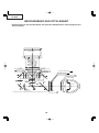
PG-B10S
SERVICE MANUAL
SERVICE-ANLEITUNG
S93J4PG-B10S/
LCD PROJECTOR
LCD PROJEKTOR
MODEL
MODELL
PG-B10S
In the interests of user-safety (Required by safety regulations in some countries) the set should be restored to its original condition and only parts identical to those specified should be used.
Im lnteresse der Benutzersicherheit (erforderliche Sicherheitsregeln in einigen Ländern) muß das Gerät in seinen
Originalzustand gebracht werden. Außerdem dürfen für die spezifizierten Bauteile nur identische Teile verwendet
werden.
SHARP CORPORATION
This document has been published to be used for
after sales service only.
The contents are subject to change without notice.
PG-B10S
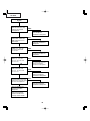
CONTENTS
Page
Page
• SPECIFICATIONS ............................................. 3
• IMPORTANT SERVICE SAFETY
NOTES (for USA) .............................................. 4
• NOTE TO SERVICE PERSONNEL ................... 5
• OPERATION MANUAL ..................................... 9
• DIMENSIONS ................................................. 17
• REMOVING OF MAJOR PARTS ..................... 18
• RESETTING THE TOTAL LAMP TIMER ......... 22
• THE OPTICAL UNIT OUTLINE ...................... 23
• ELECTRICAL ADJUSTMENT ......................... 25
• UPGRADING THE VERSION ......................... 33
• TROUBLE SHOOTING TABLE ....................... 37
•
•
•
•
•
•
•
•
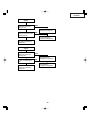
CHASSIS LAYOUT .......................................... 80
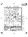
BLOCK DIAGRAM .......................................... 82
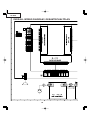
OVERALL WIRING DIAGRAM ........................ 84
DESCRIPTION OF SCHEMATIC DIAGRAM .. 86
WAVEFORMS ................................................. 87
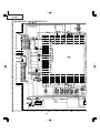
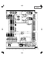
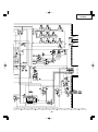
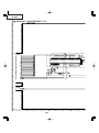
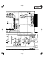
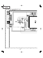
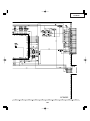
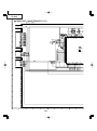
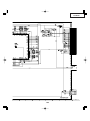
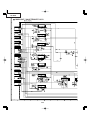
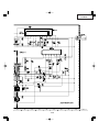
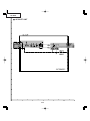
SCHEMATIC DIAGRAM .................................. 88
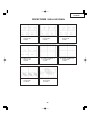
PRINTED WIRING BOARD ASSEMBLIES... 115
PARTS LIST
Ë ELECTRICAL PARTS ............................... 122
Ë CABINET AND MECHANICAL PARTS .... 132
Ë ACCESSORIES PARTS ............................ 136
Ë PACKING PARTS ...................................... 136
• PACKING OF THE SET ................................ 137
INHALT
Seite
Seite
• TECHNISCHE DATEN .................................... 43
• HINWEISE FÜR DAS
WARTUNGSPERSONAL ................................ 44
• BEDIENUNGSANLEITUNG ............................ 46
• ABMESSUNGEN ............................................ 54
• ENTFERNEN DER HAUPTTEILE .................. 55
• RÜCKSTELLEN DES
LAMPENBETRIEBSEIT-TIMERS ................... 59
• BESCHREIBUNG DER OPTIK-INHEIT .......... 60
• ELEKTRISCHE EINSTELLUNG ..................... 62
• AKTUALISIERUNG DER VERSION ............... 70
• FEHLERSUCHTABELLE ................................ 74
• CHASSIS-ANORDNUNG ............................... 80
• BLOCKSCHALTBILD ...................................... 82
• GESAMTSCHALTPLAN .................................. 84
• BESCHREIBUNG DES SCHEMATISCHEN
SCHALTPLANS .............................................. 86
• WELLENFORMEN .......................................... 87
• SCHEMATISCHER SCHALTPLAN ................. 88
• LEITERPLATTENEINHEITEN....................... 115
• ERSATZTEILLISTE
Ë ELEKTRISCHE BAUTEILE ....................... 122
Ë GEHÄUSE UND MECHANISCHE
BAUTEILE ................................................. 132
Ë ZUBEHÖRTEILE ....................................... 136
Ë VERPACKUNGSTEILE ............................. 136
• VERPACKEN DES GERÄTS ........................ 137
2
PG-B10S
Specifications
Product type LCD Projector
Model PG-B10S
Video system NTSC3.58/NTSC4.43/PAL/PAL-M/PAL-N/PAL-60/SECAM/
DTV480I/DTV480P/DTV580I/DTV580P/DTV720P/DTV1035I/DTV1080I/
DTV1080I-50
Display method LCD panel × 3, RGB optical shutter method
LCD panel Panel size: 0.55" (14.0 mm) (8.5 [H] × 11.2 [W] mm)
No. of dots: 480,000 dots (800 [H] × 600 [V])
Lens 1–1.25 × zoom lens, F1.6–1.9, f = 16.8–20.9 mm
Projection lamp 130 W AC lamp
Component input 15-pin mini D-sub connector
signal (INPUT1) Y: 1.0 Vp-p, sync negative, 75 Ω terminated
PB: 0.7 Vp-p, 75 Ω terminated
PR: 0.7 Vp-p, 75 Ω terminated
Horizontal resolution 520 TV lines (DTV720P)
Computer RGB input 15-pin mini D-sub connector
signal (INPUT 1) RGB separate/sync on green type analog input: 0–0.7 Vp-p, positive, 75 Ω terminated
HORIZONTAL SYNC. SIGNAL: TTL level (positive/negative)
VERTICAL SYNC. SIGNAL: Same as above
S-video input signal 4-pin mini DIN connector
(INPUT 2) Y (luminance signal): 1.0 Vp-p, sync negative, 75 Ω terminated
C (chrominance signal): Burst 0.286 Vp-p, 75 Ω terminated
Video input signal RCA connector: VIDEO, composite video, 1.0 Vp-p, sync negative, 75 Ω
(INPUT 3) terminated
Computer control signal (RS-232C) 9-pin mini DIN connector
Pixel clock 12–108 MHz
Vertical frequency 43–85 Hz
Horizontal frequency 15–70 kHz
Audio input signal ø3.5 mm minijack: AUDIO, 0.5 Vrms, more than 22 kΩ (stereo)
Audio output 1.0 W (monaural)
Speaker system 2.8 cm round × 1
Rated voltage AC 100–240 V
Input current 1.9 A
Rated frequency 50/60 Hz
Power consumption 185 W (Standard mode)/170 W (Eco mode) with AC 100 V
175 W (Standard mode)/160 W (Eco mode) with AC 240 V
Power consumption (standby) 4 W (AC 100 V) – 6 W (AC 240 V)
Heat dissipation 695 BTU/hour (Standard mode)/640 BTU/hour (Eco mode) with AC 100 V
660 BTU/hour (Standard mode)/600 BTU/hour (Eco mode) with AC 240 V
Operating temperature 41°F to 95°F (+5°C to +35°C)
Storage temperature –4°F to 140°F (–20°C to +60°C)
Cabinet Plastic
I/R carrier frequency 38 kHz
Dimensions (approx.) 11 37/64" × 3 5/8" × 8 3/4" (294 (W) × 92 (H) × 222 (D) mm) (main body only)
11 39/64" × 4 11/64" × 9 11/32" (294.5 (W) × 105.8 (H) × 237 (D) mm) (including adjustment foot
and projecting parts)
Weight (approx.) 6.0 lbs. (2.7 kg)
Supplied accessories Remote control, Two R-6 batteries, Power cord for U.S., Canada etc. (6', 1.8 m), Power cord
for Europe, except U.K. (6', 1.8 m), Power cord for U.K., Hong Kong and Singapore (6', 1.8
m), Power cord for Australia, New Zealand and Oceania (6', 1.8 m), RGB cable (9'10",
3.0 m), Carrying case, Lens cap (attached), Extra air filter, Lens shipping block (attached),
Projector manual and technical reference CD-ROM, “QUICK GUIDE” label, Operation manual
Replacement parts Lamp unit (Lamp/cage module) (BQC-PGB10S//1), Remote control (RRMCGA187WJSA),
Two R-6 batteries (“AA” size, UM/SUM-3, HP-7, or similar), Power cord for U.S., Canada etc.
(QACCDA016WJPZ), Power cord for Europe, except U.K. (QACCVA006WJPZ), Power cord
for U.K., Hong Kong and Singapore (QACCBA015WJPZ), Power cord for Australia, New
Zealand and Oceania (QACCLA005WJPZ), RGB cable (QCNWGA012WJPZ), Carrying case
(GCASNA009WJSA), Lens cap (CCAPHA004WJ01), Air filter (PFILDA010WJZZ), Lens shipping block (SPAKXA333WJZZ), Projector manual and technical reference CD-ROM
(UDSKAA039WJZZ), “QUICK GUIDE” label (TLABZA439WJZZ), Operation manual (TINSA917WJZZ)
As a part of policy of continuous improvement, SHARP reserves the right to make design
and specification changes for product improvement without prior notice. The performance
specification figures indicated are nominal values of production units. There may be
some deviations from these values in individual units.
3
PG-B10S
IMPORTANT SERVICE SAFETY NOTES (for USA)
Ë Service work should be performed only by qualified service technicians who are
thoroughly familiar with all safety checks and servicing guidelines as follows:
» Use an AC voltmeter with sensitivity of 5000 ohm per
volt., or higher, sensitivity to measure the AC voltage
drop across the resistor (See Diagram).
» All checks must be repeated with the AC plug
connection reversed. (If necessary, a non-polarized
adapter plug must be used only for the purpose of
completing these checks.)
Any reading of 0.3 volts RMS (this corresponds to 0.2
milliamp. AC.) or more is excessive and indicates a
potential shock hazard which must be corrected before
returning the unit to the owner.
WARNING
1. For continued safety, no modification of any circuit
should be attempted.
2. Disconnect AC power before servicing.
BEFORE RETURNING THE PROJECTOR:
(Fire & Shock Hazard)
Before returning the projector to the user, perform
the following safety checks:
1. Inspect lead wires are not pinched between the chassis
and other metal parts of the projector.
2. Inspect all protective devices such as non-metallic
control knobs, insulating materials, cabinet backs,
adjustment and compartment covers or shields,
isolation resistor-capacity networks, mechanical
insulators, etc.
3. To be sure that no shock hazard exists, check for
current leakage in the following manner:
» Plug the AC cord directly into a 120-volt AC outlet,
(Do not use an isolation transformer for this test).
» Using two clip leads, connect a 1.5k ohm, 10 watt
resistor paralleled by a 0.15µF capacitor in parallel
between all exposed metal cabinet parts and earth
ground.
AC
VOLTMETER
1.5k ohm (10W)
0.15µF
TEST PROBE
TO EXPOSED
METAL PARTS
CONNECT TO KNOWN
EARTH GROUND
12345678901234567890123456789012123456789012345678901234567890121234567890123456789012345678901212
12345678901234567890123456789012123456789012345678901234567890121234567890123456789012345678901212
12345678901234567890123456789012123456789012345678901234567890121234567890123456789012345678901212
SAFETY NOTICE
AVIS POUR LA SECURITE
Many electrical and mechanical parts in LCD Projector
have special safety-related characteristics.
These characteristics are often not evident from visual
inspection, nor can protection afforded by them be
necessarily increased by using replacement components
rated for higher voltage, wattage, etc.
Replacement parts which have these special safety
characteristics are identified in this manual; electrical
components having such features are identified by “å”
and shaded areas in the Replacement Parts Lists and
Schematic Diagrams. For continued protection,
replacement parts must be identical to those used in
the original circuit. The use of a substitute replacement
parts which do not have the same safety characteristics
as the factory recommended replacement parts shown
in this service manual, may create shock, fire or other
hazards.
De nombreuses pièces, électriques et mécaniques, dans
les projecteur à LCD présentent des caractéristiques
spéciales relatives à la sécurité, qui ne sont souvent pas
évidentes à vue.
Le degré de protection ne peut pas être nécessairement
augmentée en utilisant des pièces de remplacement
étalonnées pour haute tension, puissance, etc.
Les pièces de remplacement qui présentent ces
caractéristiques sont identifiées dans ce manuel;
les pièces électriques qui présentent ces particularités
sont identifiées par la marque “å” et hachurées dans la
liste des pièces de remplacement et les diagrammes
schématiques. Pour assurer la protection, ces pièces
doivent être identiques à celles utilisées dans le circuit
d’origine. L’utilisation de pièces qui n’ont pas les mêmes
caractéristiques que les pièces recommandées par l’usine,
indiquées dans ce manuel, peut provoquer des
électrocutions, incendies ou autres accidents.
WARNING: The bimetallic component has the primary
conductive side exposed. Be very careful in
handling this component when the power is on.
AVERTISSEMENT: La composante bimétallique dispose du
conducteur primaire dénudé. Faire attention
lors de la manipulation de cette
composante sous tension.
12345678901234567890123456789012123456789012345678901234567890121234567890123456789012345678901212
12345678901234567890123456789012123456789012345678901234567890121234567890123456789012345678901212
12345678901234567890123456789012123456789012345678901234567890121234567890123456789012345678901212
4
PG-B10S
NOTE TO SERVICE
NOTE POUR LE PERSONNEL
PERSONNEL
D’ENTRETIEN
123456789012345678901234567890121234567890123456 123456789012345678901234567890121234567890123456
123456789012345678901234567890121234567890123456
123456789012345678901234567890121234567890123456
123456789012345678901234567890121234567890123456
123456789012345678901234567890121234567890123456
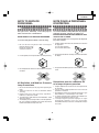
UV-RADIATION PRECAUTION
123456789012345678901234567890121234567890123456
123456789012345678901234567890121234567890123456
PRECAUTION POUR LES RADIATIONS UV
123456789012345678901234567890121234567890123456
123456789012345678901234567890121234567890123456
The light source, UHP lamp, in the LCD projector
emits small amounts of UV-Radiation.
La source de lumière, la lampe UHP, dans le projecteur
LCD émet de petites quantités de radiation UV.
AVOID DIRECT EYE AND SKIN EXPOSURE.
EVITEZ TOUTE EXPOSITION DIRECTE DES
YEUX ET DE LA PEAU.
To ensure safety please adhere to the following:
Pour votre sécurité, nous vous prions de respecter
les points suivants:
1. Toujours porter des lunettes de soleil lors d’un entretien
du projecteur
avec la lampe allumée
et le haut du coffret retiré.
1. Be sure to wear sun-glasses when servicing the
projector with the lamp
turned “on” and the top
enclosure removed.
2. Ne pas faire fonctionner la lampe à l’extérieur du boîtier
de lampe.
2. Do not operate the lamp outside of the lamp housing.
3. Ne pas faire fonctionner plus de 2 heures avec le coffret
retiré.
3. Do not operate for more than 2 hours with the enclosure
removed.
Précautions pour les radiations UV
UV-Radiation and Medium Pressure
et la lampe moyenne pression
Lamp Precautions
1. Toujours débrancher la fiche AC lors du remplacement
de la lampe.
2. Laisser l’unité refroidir pendant une heure avant de
procéder à l’entretien.
3. Ne remplacer qu’avec une lampe du même type. Type
BQC-PGB10S//1, caractéristique 100V/130W.
4. La lampe émet de petites quantités de radiation UVéviter tout contact direct avec les yeux.
5. La lampe moyenne pression implique un risque
d’explosion. Toujours suivre les instr uctions
d’installation décrites ci-dessous et manipuler la lampe
avec soin.
1. Be sure to disconnect the AC plug when replacing the
lamp.
2. Allow one hour for the unit to cool down before
servicing.
3. Replace only with same type lamp. Type BQCPGB10S//1 rated 100V/130W.
4. The lamp emits small amounts of UV-Radiation, avoid
direct-eye contact.
5. The medium pressure lamp involves a risk of explosion.
Be sure to follow installation instructions described
below and handle the lamp with care.
5
PG-B10S
123456789012345678901234567890121234567890123456
123456789012345678901234567890121234567890123456
123456789012345678901234567890121234567890123456
123456789012345678901234567890121234567890123456
UV-RADIATION PRECAUTION (Continued)
123456789012345678901234567890121234567890123456
123456789012345678901234567890121234567890123456
PRECAUTION POUR LES RADIATIONS UV (Suite)
123456789012345678901234567890121234567890123456
123456789012345678901234567890121234567890123456
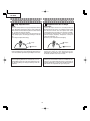
Lamp Replacement
Remplacement de la lampe
Note:
Remarque:
Since the lamp reaches a very high temperature during
units operation replacement of the lamp should be
done at least one hour after the power has been turned
off. (to allow the lamp to cool off.)
Installing the new lamp, make sure not to touch the
lamp (bulb) replace the lamp by holding its reflector
2.
[Use original replacement only.]
Comme la lampe devient très chaude pendant le
fonctionnement de l’unité, son remplacement ne doit
être effectué au moins une heure après avoir coupé
l’alimentation (pour permettre à la lampe de refroidir).
En installant la nouvelle lampe, s’assurer de ne pas
toucher la lampe (ampoule). Remplacer la lampe en
tenant son réflecteur 2.
[N’utiliser qu’un remplacement d’origine.]
1 Lampe
1 Lamp
2 Reflecteur
2 Reflector
DANGER ! –– Never turn the power on without the
lamp to avoid electric-shock or damage of the devices
since the stabilizer generates high voltages at its start.
DANGER ! –– Ne jamais mettre sous tension sans la
lampe pour éviter un choc électrique ou des
dommages des appareils car le stabilisateur génère
de hautes tensions à sa mise en route.
Since small amounts of UV-radiation are emitted
from an opening between the exhaust fans, it is recommended to place the cap of the optional lens on
the opening during servicing to avoid eye and skin
exposure.
Comme de petites quantités de radiation UV sont
émises par une ouverture entre les ventilateurs aspirants, il est recommandé de placer le capuchon de
l’optique optionnelle sur l’ouverture pendant l’entretien
pour éviter une exposition des yeux et la peau.
6
PG-B10S
WARNING:
High brightness light source, do not stare into the beam of light, or view directly. Be especially
careful that children do not stare directly in to the beam of light.
WARNING:
TO REDUCE THE RISK OF FIRE OR ELECTRIC SHOCK, DO NOT EXPOSE THIS UNIT TO
MOISTURE OR WET LOCATIONS.
CAUTION
The lighting flash with arrowhead within a
triangle is intended to tell the user that
parts inside the product are risk of electric
shock to persons.
RISK OF ELECTRIC SHOCK.
DO NOT REMOVE SCREWS
EXCEPT SPECIFIED USER
SERVICE SCREW.
CAUTION: TO REDUCE THE RISK OF ELECTRIC SHOCK,
DO NOT REMOVE CABINET.
NO USER-SERVICEABLE PARTS EXCEPT LAMP UNIT.
REFER SERVICING TO QUALIFIED SERVICE
PERSONNEL.
The exclamation point within a triangle is
intended to tell the user that important
operating and servicing instructions are in
the manual with the projector.
CAUTION
(POWER Unit)
For continued
protection against a
risk of fire, replace
only with same type
5.0A 250V 5.0A, AC250V fuse.
(F701)
12345678901234567890123456789012123456789012345678901234567890121234567890123456789012345678901212
12345678901234567890123456789012123456789012345678901234567890121234567890123456789012345678901212
12345678901234567890123456789012123456789012345678901234567890121234567890123456789012345678901212
AVERTISSEMENT: Source lumineuse de grande intensité. Ne pas fixer le faisceau lumineux ou le regarder
directement. Veiller particulièrement à éviter que les enfants ne fixent directement le
faisceau lumineux.
AVERTISSEMENT: AFIN D’EVITER TOUT RISQUE D’INCENDIE OU D’ELECTROCUTION, NE PAS PLACER
CET APPAREIL DANS UN ENDROIT HUMIDE OU MOUILLE.
ATTENTION
L’éclair terminé d’une flèche à l’intérieur
d’un triangle indique à l’utilisateur que les
pi‘eces se trouvant dans l’appareil sont
susceptibles de provoquer une décharge
électrique.
RISQUE
D’ÉLECTROCUTION. NE
PASR ETIRER LES VIS Á
L’EXCEPTION DE LA VIS DE
REPARATION UTILISATEUR
SPECIFIEES
Le point d’exclamation à l’intérieur d’un
triangle indique à l’utilisateur que les
instructions de fonctionnement et
d’entretien sont détaillées dans les
documents fournis avec le projecteur.
ATTENTION: POUR EVITER TOUT RISQUE
D’ELECTROCUTION, NE PAS RETIRER LE CAPOT.
AUCUNE DES PIECES INTERIEURES N’EST REPARABLE
PAR L’UTILISATEUR, A L’EXCEPTION DE L’UNITE DE
LAMPE. POUR TOUTE REPARATION, S’ADRESSER A UN
TECHNICIEN D’ENTRETIEN QUALIFIE.
PRECAUTION
(Unité de PUTSSANCE)
Pour une protection
continue contre un
risques d’incendie, ne
remplacer qu’avec un
fusible 5.0A,AC250V
5.0A 250V du même type.
(F701)
7
PG-B10S
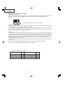
Precautions for using lead-free solder
1 Employing lead-free solder
"PWBs" of this model employs lead-free solder. The LF symbol indicates lead-free solder, and is attached on the
PWBs and service manuals. The alphabetical character following LF shows the type of lead-free solder.
Example:
LFa
Indicates lead-free solder of tin, silver and copper.
2 Using lead-free wire solder
When fixing the PWB soldered with the lead-free solder, apply lead-free wire solder. Repairing with conventional
lead wire solder may cause damage or accident due to cracks.
As the melting point of lead-free solder (Sn-Ag-Cu) is higher than the lead wire solder by 40°C, we recommend you
to use a dedicated soldering bit, if you are not familiar with how to obtain lead-free wire solder or soldering bit,
contact our service station or service branch in your area.
3 Soldering
As the melting point of lead-free solder (Sn-Ag-Cu) is about 220°C which is higher than the conventional lead solder
by 40°C, and as it has poor solder wettability, you may be apt to keep the soldering bit in contact with the PWB for
extended period of time. However, since the land may be peeled off or the maximum heat-resistance temperature of
parts may be exceeded, remove the bit from the PWB as soon as you confirm the steady soldering condition.
Lead-free solder contains more tin, and the end of the soldering bit may be easily corroded. Make sure to turn on
and off the power of the bit as required.
If a different type of solder stays on the tip of the soldering bit, it is alloyed with lead-free solder. Clean the bit after
every use of it.
When the tip of the soldering bit is blackened during use, file it with steel wool or fine sandpaper.
Be careful when replacing parts with polarity indication on the PWB silk.
Lead-free wire solder for servicing
Part No.
ZHNDAi123250E
ZHNDAi126500E
ZHNDAi12801KE
★
J
J
J
Description
φ0.3mm
250g(1roll)
φ0.6mm
500g(1roll)
φ1.0mm
1kg(1roll)
8
Code
BL
BK
BM
PG-B10S
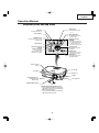
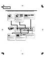
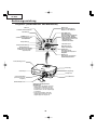
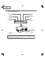
Operation Manual
Projector (Front and Top View)
INPUT button
ON button
For switching input mode
1, 2 or 3.
For turning the power on.
Power indicator
KEYSTONE button
For entering the Keystone
Correction mode.
STANDBY button
Adjustment buttons
('"\ |)
For putting the projector into the
standby mode.
• For selecting menu items.
• For adjusting the Keystone
Correction when in the
Keystone Correction mode.
Lamp indicator
Volume buttons
Temperature warning
indicator
For adjusting the speaker
sound level.
AUTO SYNC button
For automatically
adjusting images when
connected to a computer.
ENTER button
For setting items selected
or adjusted on the menu.
MENU button
For displaying adjustment
and setting screens.
Remote control
sensor
Focus ring
Zoom knob
Intake vent
Speaker
Front adjustment foot
(on the bottom of
the projector)
Lens shift lever
HEIGHT ADJUST button
Attaching and removing the lens cap
• Press on the two buttons of the lens cap
and attach it to the lens, then release the
buttons to lock it in place.
• Press on the two buttons of the lens cap
and remove it from the lens.
9
PG-B10S
About the Indicators on the Projector
Power indicator
Green on/Red on ... Normal
Red blinks ... Abnormal
Lamp indicator
Green on ... Normal
Green blinks ... The lamp is warming up.
Red on ... Change the lamp.
Temperature warning indicator
Off ... Normal
Red on ... The internal temperature is abnormally high.
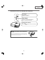
Attaching and Removing the Lens Shipping Block
When attaching the lens shipping block, be sure to return the
lens shift lever to the center position. If the lens is shifted upward
or downward, the lens shipping block cannot be attached.
10
PG-B10S
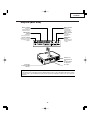
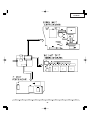
Projector (Rear View)
INPUT 1 terminal
INPUT 2 terminal
Terminal for
computer RGB and
component signals.
Terminal for
connecting video
equipment with an
S-video terminal.
RGB OUTPUT
terminal
INPUT 3 terminal
Terminal for
connecting video
equipment.
Terminal for
connecting a monitor.
RS-232C terminal
AUDIO INPUT
terminal
Terminal for controlling
the projector using a
computer.
Shared audio input
terminal for INPUT
1, 2 and 3.
Exhaust vent
Rear adjustment
foot
(on the bottom of
the projector)
AC socket
Kensington
Security Standard
connector
Using the Kensington Lock
• This projector has a Kensington Security Standard connector for use with a Kensington MicroSaver Security
System. Refer to the information that came with the system for instructions on how to use it to secure the
projector.
11
PG-B10S
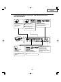
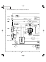
INPUT/OUTPUT Terminals and Connectable Main Equipment
RS-232C terminal
Connecting the
computer to control the
projector.
INPUT 1 terminal
INPUT 3 terminal
Connecting the computer.
(See page 51.)
Connecting video equipment
with component output
terminal (DVD player, DTV
decoder, etc.).
Connecting video equipment without
S-video output terminal.
AUDIO INPUT terminal
RGB OUTPUT terminal
Connecting the monitor
when you want to
simultaneously watch the
projection image on the
monitor.
INPUT 2 terminal
Connecting video equipment with
S-video output terminal (VCR,
Laser disc player, etc.).
12
Connecting an audio cable
(Shared audio input terminal
for INPUT 1, 2 and 3.)
PG-B10S
Remote Control (Front View)
ON button
STANDBY button
For turning the power on.
For putting the projector into the
standby mode.
MENU button
KEYSTONE button
For displaying adjustment and
setting screens.
For entering the Keystone
Correction mode.
Adjustment buttons
(' " \ |)
UNDO button
• For selecting menu items.
• For adjusting the Keystone
Correction when in the Keystone
Correction mode.
For undoing an operation or
returning to the previous display.
FORWARD/BACK buttons
ENTER button
Same function as the [Page Down]
and [Page Up] keys on a computer
keyboard when using the optional
Remote Receiver (AN-MR1EL).
For setting items selected or
adjusted on the menu.
FREEZE button
For freezing images.
ENLARGE (Enlarge/Reduce)
buttons
AV MUTE button
For enlarging or reducing part of
the image.
For temporarily displaying the
black screen and turning off the
sound.
AUTO SYNC button
For automatically adjusting images
when connected to a computer.
RESIZE button
For switching the screen size
(NORMAL, BORDER, etc.).
INPUT buttons
For switching to the respective
input modes.
Volume buttons
For adjusting the speaker sound
level.
13
PG-B10S
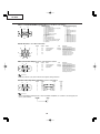
Connection Pin Assignments
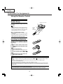
Using the Remote Control
Usable Range
Remote control sensor
The remote control can be used to control
the projector within the ranges shown in the
illustration.
30°
Note
30°
• The signal from the remote control can be reflected off a screen for easy operation. However, the effective distance of the signal may
differ depending on the screen material.
Remote
control
signal
transmitters
30°
23' (7 m)
When using the remote control:
• Be sure not to drop, expose to moisture or high
temperature.
• The remote control may malfunction under a
fluorescent lamp. In this case, move the projector away from the fluorescent lamp.
Remote control
Inserting the Batteries
The batteries (two R-6 batteries (“AA” size,
UM/SUM-3, HP-7 or similar)) are supplied in
the package.
1
Press the ▲ mark on the cover
and slide it in the direction of the
arrow.
2
Insert the batteries.
3
Attach the cover and slide it until it clicks into place.
• Insert the batteries making sure the poand
larities correctly match the
marks inside the battery compartment.
Incorrect use of the batteries may cause them to leak or explode. Please follow the precautions below.
Caution
• Insert the batteries making sure the polarities correctly match the
and
marks inside the battery compartment.
• Batteries of different types have different properties, therefore do not mix batteries of different types.
• Do not mix new and old batteries.
This may shorten the life of new batteries or may cause old batteries to leak.
• Remove the batteries from the remote control once they have run out, as leaving them in can cause them to leak.
Battery fluid from leaked batteries is harmful to skin, therefore be sure to first wipe them and then remove them
using a cloth.
• The batteries included with this projector may run down in a short period, depending on how they are kept. Be
sure to replace them as soon as possible with new batteries.
• Remove the batteries from the remote control if you will not be using the remote control for a long time.
14
PG-B10S
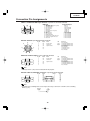
Connection Pin Assignments
INPUT 1 and OUTPUT RGB Signal Terminal: 15-pin Mini D-sub female connector
RGB Input
10
5
6
1
15
11
1.
2.
3.
4.
5.
6.
7.
8.
9.
10.
11.
12.
13.
14.
15.
Component Input
Video input (red)
Video input (green/sync on green)
Video input (blue)
Not connected
Not connected
Earth (red)
Earth (green/sync on green)
Earth (blue)
Not connected
GND
Not connected
Bi-directional data
Horizontal sync signal: T TL level
Vertical sync signal: TTL level
Data clock
1.
2.
3.
4.
5.
6.
7.
8.
9.
10.
11.
12.
13.
14.
15.
PR (CR)
Y
PB (CB)
Not connected
Not connected
Earth (PR)
Earth (Y)
Earth (PB)
Not connected
Not connected
Not connected
Not connected
Not connected
Not connected
Not connected
RS-232C Terminal: 9-pin Mini DIN female connector
8
9
7
6
3
Pin No.
1
2
3
4
5
6
7
8
9
Signal
Name
RD
SD
Receive Data
Send Data
SG
Signal Ground
I/O
Input
Output
RS
CS
Reference
Not connected
Connected to internal circuit
Connected to internal circuit
Not connected
Connected to internal circuit
Not connected
Connected to Pin 8
Connected to Pin 7
Not connected
4
5
2
1
DIN-D-sub RS-232C adaptor: 9-pin D-sub male connector
1
6
5
9
Pin No.
1
2
3
4
5
6
7
8
9
Signal
Name
RD
SD
Receive Data
Send Data
SG
Signal Ground
I/O
Input
Output
RS
CS
Reference
Not connected
Connected to internal circuit
Connected to internal circuit
Not connected
Connected to internal circuit
Not connected
Connected to internal circuit
Connected to internal circuit
Not connected
Note
• Pin 8 (CS) and Pin 7 (RS) are short circuited inside the projector.
RS-232C Cable recommended connection: 9-pin D-sub female connector
5
9
1
6
Pin No.
1
2
3
4
5
6
7
8
9
Signal
CD
RD
SD
ER
SG
DR
RS
CS
CI
Pin No.
1
2
3
4
5
6
7
8
9
Signal
CD
RD
SD
ER
SG
DR
RS
CS
CI
Note
• Depending on the controlling device used, it may be necessary to connect Pin 4 and Pin 6 on the controlling
device (e.g. PC).
Projector
PC
Pin No.
4
5
6
Pin No.
4
5
6
15
PG-B10S
RS-232C Specifications and Command Settings
PC control
A computer can be used to control the projector by connecting an RS-232C serial control cable (cross type,
sold separately) to the projector. (See page 54 for connection.)
Communication conditions
Set the serial port settings of the computer to match that of the table.
Signal format: Conforms to RS-232C standard.
Parity bit: None
Baud rate: 9,600 bps
Stop bit: 1 bit
Data length: 8 bits
Flow control: None
Basic format
Commands from the computer are sent in the following order: command, parameter, and return code. After
the projector processes the command from the computer, it sends a response code to the computer.
Command format
C1
C2
C3 C4
P1
P2
P3
Command 4-digit
Response code format
Normal response
O
Info
K
P4
Return code (0DH)
Parameter 4-digit
Problem response (communication error or incorrect command)
E
Return code (0DH)
R
R
Return code (0DH)
• When controlling the projector using RS-232C commands from a computer, wait for at least 30 seconds after
the power has been turned on, and then transmit the commands.
• When more than one code is being sent, send each command only after the response code for the previous
command from the projector is verified.
Commands
Example: When turning on the projector, make the following setting.
Computer
P
O
W
R
BUTTONS & REMOTE CONTROL KEY
CONTROL CONTENTS
_
_
_
1
COMMAND PARAMETER
Projector
→
←
O
K
RETURN
Standby
P O W R _ _ _ 0 OK or ERR
Power On
P O W R _ _ _ 1 OK or ERR
INPUT1
I R G B _ _ _ 1 OK or ERR
INPUT2
I V E D _ _ _ 1 OK or ERR
INPUT3
I V E D _ _ _ 2 OK or ERR
INPUT1 SIGNAL TYPE : AUTO
I A S I _ _ _ 0 OK or ERR
INPUT1 SIGNAL TYPE : RGB
I A S I _ _ _ 1 OK or ERR
INPUT1 SIGNAL TYPE : COMPONENT
I A S I _ _ _ 2 OK or ERR
Lamp Usage Time (hour)
T L T T _ _ _ 1 0~9999
Remaining Lamp Life (Percentage)
T L T L _ _ _ 1 0~100
Lamp Status
T L P S _ _ _ 1 0:Off, 1:On, 2:Retry, 3:Waiting, 4:Lamp Error
Unit Status
T A B N _ _ _ 1 0:Normal, 1:Temp High, 2:Fan Err,
4:Filter or lamp Cover Err, 8:Lamp Life 5% or less,
16:Lamp Burnt-out, 32:Lamp Not Lit,
64:Temp Abnormally High
Model Name Check
T N A M _ _ _ 1 PROJECTOR NAME
AV Mute Off
I M B K _ _ _ 0 OK or ERR
AV Mute On
I M B K _ _ _ 1 OK or ERR
Auto Sync Start
A D J S _ _ _ 1 OK or ERR
Note
• If an underbar (_) appears in the parameter column, enter a space. If an asterisk (*) appears, enter a
value in the range indicated in brackets under CONTROL CONTENTS.
16
PG-B10S
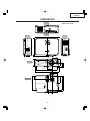
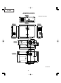
DIMENSIONS
Rear View
Units: inches (mm)
Top View
11 37/64 (294)
Side View
1 31/32 (49.7)
2 1/4 (57)
8 9/64 (206.5)
3 5/8 (92)
Front View
2 17/32 (64)
1 45/64 (43.2) 1 59/64 (48.8)
ø 65
7 15/ 32 (189.5)
19/32 (15)
8 3/4 (222)
Side View
2 25/64 (60.4)
2 17/32 (64.2)
7 45/64 (195.6)
3 27/64 (86.6)
8 11/64 (207.4)
7 43/64 (194.5)
Bottom View
2 9/16 (65)
3 59/64 (99.5)
1 61/64 (49.5)
1 1/8 (28.5)
1 25/32 (45)
17
PG-B10S
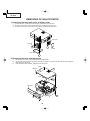
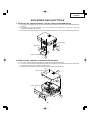
REMOVING OF MAJOR PARTS
1. Detaching the lamp unit cover and filter cover
1-1. Remove the lock screw from the lamp cover, and detach the lamp cover.
1-2. Remove the two lock screws from the lamp unit, and detach the lamp unit.
1-3. Remove the one lock screws from the filter cover, and detach the filter cover.
Filter cover
Lamp unit
1-2
1-3
Air filter
1-2
Lamp cover
1-1
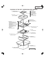
2. Removing the front and top panels
2-1. Remove the seven lock screws from the front and top panels.
2-2. Lift the right-hand side of the top panel, and undo the hooks at the front and left-hand side of the top panel.
Now detach the top panel.
2-3. Undo the arrow-marked hooks, and detach the front panel.
Hook
Top panel
2-1
Hook
2-2
Front panel
2-3
2-3
2-2
18
PG-B10S
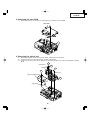
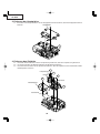
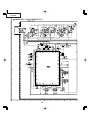
3. Detaching the main PWB
3-1. Remove the two lock screws from the main PWB unit, and detach the main PWB.
Main PWB
[FD]
[EA]
[RP]
[GP]
[FA]
[RP]
[TH]
[FB]
[LF]
[TI] [SP]
3-1
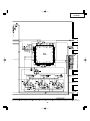
4. Removing the optical unit
4-1. Remove the two lock screws from the lamp socket, and detach the lamp socket.
4-2. Remove the lock screw from the bimetal, and detach the bimetal.
4-3. Remove the five lock screws from the optical unit, and detach the optical unit, side shield and power insulating
board.
4-1
Lamp socket
4-2
Bimetal
4-3
4-3
Optical unit
Power insulating board
4-3
Side shield
19
PG-B10S
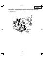
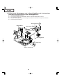
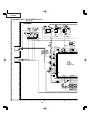
5. Detaching the power PWB/ballast PWB unit
5-1. Remove the four lock screws from the power PWB/ballast PWB unit, and detach the power PWB/ballast
PWB unit.
5-2. Detach the insulating board.
5-3. Detach the ballast PWB.
5-1
Power PWB
Top shield
5-2
Ballast PWB
5-3
Bottom shield
5-1
20
PG-B10S
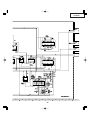
6. Detaching the AC inlet, exhaust fan, speaker, suction duct and suction fan
6-1.
6-2.
6-3.
6-4.
6-5.
Detach the AC inlet PWB.
Remove the lock screw from the exhaust fan, and detach the exhaust fan.
Detach the speaker.
Remove the two lock screws from the suction duct, and detach the suction duct.
Detach the suction fan.
Suction duct
6-4
Exhaust fan
Leaf switch
AC inlet PWB
Suction fan
Speaker
Bottom panel
21
PG-B10S
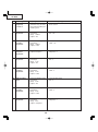
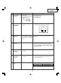
RESETTING THE TOTAL LAMP TIMER
● Resetting the total lamp timer
When replacing the lamp, reset the total lamp timer in the procedure below.
Resetting the Lamp Timer
Reset the lamp timer after replacing the lamp.
1
Connect the power cord.
2
Reset the lamp timer.
• Plug the power cord into the AC socket
of the projector.
AC socket
• While simultaneously holding down
and
and
ON button
on the projector, press
on the projector.
• “LAMP 0000H” is displayed, indicating
that the lamp timer is reset.
buttons
Info
• Make sure to reset the lamp timer only
when replacing the lamp. If you reset the
lamp timer and continue to use the same
lamp, this may cause the lamp to become
damaged or explode.
AUTO SYNC
button
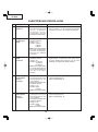
■ The warning lights on the projector indicate problems inside the projector.
■ If a problem occurs, either the temperature warning indicator or the lamp replacement indicator will illuminate red, and the power will turn off. After the power has been turned off, follow the proce-duresgiven
below.
Maintenance indicator
Normal
Power
indicator
Condition
Problem
Possible Solution
• Relocate the projector to an area
with proper ventilation.
• Clean the air filter of the projector.
Temperature
warning
indicator
Lamp
indicator
Abnormal
Off
Red on/
Standby
Green on Red on
Green blinks
when the
lamp is
warming up. Red on/
Standby
Green on/
Red on
Red blinks
• Blocked air intake
The internal
temperature is
• Take the projector to your nearest
abnormally high. • Cooling fan breakdown
Sharp Authorized Projector Dealer
• Internal circuit failure or Service Center for repair.
• Clogged air intake
Time to change
the lamp.
The lamp does
not illuminate.
The power
indicator blinks
in red when the
projector is on.
• Carefully replace the lamp.
• Remaining lamp life
Take the projector to your nearest
becomes 5% or less. • Sharp Authorized Projector Dealer
or Service Center for repair.
Please exercise care when
• Burnt-out lamp
• replacing the lamp.
• Lamp circuit failure
• The filter cover or
lamp unit cover is
open.
• Securely install the cover.
• If the power indicator blinks in red
even when the filter cover and
lamp unit cover is securely
installed, contact your nearest
Sharp Authorized Projector Dealer
or Service Center for advice.
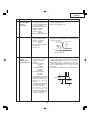
■ Replacing the Air Filter
• This projector is equipped with air filters to ensure the optimal operating
condition of the projector.
• The air filters should be cleaned every
100 hours of use. Clean the filters more
often when the projector is used in a
dusty or smoky location.
• Ask your nearest Sharp Authorized Projector Dealer or Service Center to exchange the filter (PFILDA010WJZZ)
when it is no longer possible to clean.
" Bottom view
" Front view
Air filter (removable)
4
Remove the air filter.
5
Clean the air filter.
6
Replace the air filter.
7
Replace the filter cover.
Air filter (not removable)
• Pick the air filter up with your fingers and
lift it out of the filter cover.
• Clean the dust off the air filter and cover
with a vacuum cleaner extension hose.
STANDBY button
Cleaning and Replacing
the Air Filter
1
STANDBY
STANDBY
button
Press
on the projector
STANDBY
or
on the remote control to
put the projector into the
standby mode.
• Place the air filter underneath the tabs
on the filter cover.
• Wait until the cooling fan stops.
2
Disconnect the power cord.
• Unplug the power cord from the AC
socket.
AC socket
• Align the tab on the filter cover and place
it while pressing the tab to close it (1).
Then tighten the user service screw (2)
to secure the filter cover.
Tab
1
User service screw
1
3
Remove the filter cover.
• Turn the projector over. Loosen the user
service screw (1) that secures the filter cover. Pressing the tab, remove the
filter cover (2).
2
Tab
2
Note
• Be sure the filter cover is securely installed.
The power will not turn on unless it is
correctly installed.
• If dust or dirt has collected inside the rear
and bottom air filters (not removable), clean
the filter with a vacuum cleaner extension
hose.
User service screw
22
PG-B10S
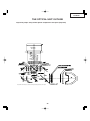
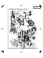
THE OPTICAL UNIT OUTLINE
Layout for proper setup of the optical components and parts (top view)
Place the M1 and M2 reflectors so that their markings should be positioned as shown above.
23
PG-B10S
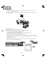
<Replacing the prism holder>
1. Remove the two lock screws from the prism holder, and detach the prism holder out of the optical unit.
2. Fit a new prism holder in the optical unit.
Note: Even if only the LCD is defective, replace the entire prism holder with new one. Do not change the LCD
alone for new one.
1
Prism holder
<Optical axis adjustment>
This adjustment is needed if black fringe appears on the screen.
To do this, readjust the fly-eye lens (for the incident light). First detach the top panel.
1. Disconnect the LCD flat cable from the main PWB connector.
2. Remove the lock screws from the main PWB, and slide the main PWB out of position.
3. Turn on the power and make sure the lamp lights up.
4. Using a hex wrench, loosen the fly-eye adjustment plate lock screws.
5. Using the specific eccentric cam adjustment wrench, turn the eccentric cams. The eccentric cam (2) is for
adjusting the x axis (horizontal). The eccentric cams (1) and (3) are for adjusting the y axis (vertical) and the
θz axis, respectively.
6. Finally, tighten up the lock screws.
Note 1: The eccentric cams are used for this adjustment. This means that their turning and the optical axis
movement do not linearly correspond to each other.
Eccentric cam (1)
(y- and θz-axis adjustment)
Fly-eye adjustment tools
Tool
Eccentric cam adjustment wrench
Hex wrench
Specific/General-purpose
Specific
General-purpose
Tool's part code
9DASPN-XGNV1U
9EQLNC-XGNV1U
9EQLNC-XGNV4U
Eccentric cam (2)
(x-axis adjustment)
Fly-eye adjustment plate lock screws.
Eccentric cam (3)
(y- and θz-axis adjustment)
Fly-eye lens
24
PG-B10S
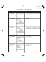
ELECTRICAL ADJUSTMENT
No.
Adjusting point
Adjusting conditions
Adjusting procedure
EEPROM
initialization
1. Turn on the power (with the
lamp on) and warm up the
set for 15 minutes.
» Make the following settings.
Press S2002 to call the process mode and execute
"SS2" on SS menu.
2-1 R/G/B Brightness adjustment
1. Select the following group
and subjects.
Group : AD
Subject : R-Bright
G-Bright
B-Bright
(Process GAMMA interlock)
2. Feed the SVGA 16-step signal with an amplitude level
of 50% (0.35 Vp-p).
1.Check the setting valve.
R/G/B-Bright: 63
2-2 R/G/B Contrast
adjustment
1. Select the following group
and subjects.
Group : AD
Subject : R-Contrast
G-Contrast
B-Contrast
(Process GAMMA interlock)
2. Feed the SVGA white signal with an amplitude level
of 96% (0.67 Vp-p).
1.Watching the screen, adjust the R-, G- and B-Contrast settings so that because of some pixel dropouts, the bright color zone should become just about
a half.
1
3
DTV Brightness/
Contrast adjustment
1. Feed a 480P component
10-step signal with 100%
amplitude.
2. Select the following group
and subjects.
Group : DTV
Subject : Bright
Contrast
(Process GAMMA interlock)
1. Check the setting value.
Contrast (White Level): 45
Bright (Black Level):
32
4
DVD Brightness/
Contrast adjustment
1. Feed a 480I component 10step signal with 100%
amplitude.
2. Select the following group
and subjects.
Group : DVD
Subject : Bright
Contrast
(Process GAMMA interlock)
1. Check the setting value.
Contrast (White Level): 46
Bright (Black Level):
34
25
PG-B10S
No.
Adjusting point
Adjusting conditions
Adjusting procedure
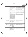
5
Video Brightness/Contrast
adjustment
1. Feed an NTSC composite
video 10-step signal (no
setup) with 100% amplitude.
2. Select the following group
and subjects.
Group : VIDEO
Subject : Bright
Contrast
(Process GAMMA interlock)
1. Check the setting value.
Contrast (White Level): 43
Bright (Black Level):
142
6
PSIG adjustment
1. Select the following group
and subjects.
Group : OUTPUT2
Subject : PSIG-H
PSIG-L
2. Check the fixed value.
PSIG-H: 140
PSIG-L: 105
1. Feed the SVGA signal and adjust to make the following PSIG waveform. (TP1201)
6.8V DC
(typ)
2.0V DC
(typ)
GND
Adjust with PSIG-H
Adjust with PSIG-L
7
R/G/B Black
Level Signal
Amplitude
adjustment
1. Select the following group
and subjects.
Group : OUTPUT1
Subject :
On Green adjustment
(G1-BLK)
G1-GAIN
On Red Adjustment
(R1-BLK)
R1-GAIN
On Blue Adjustment
(B1-BLK)
B1-GAIN
2. Make sure the process adjustment color bags appear
onscreen.
3. Connect a oscilloscope to
pin(2) of P1302 for the G
setting.
4. Connect the oscilloscope to
pin(1) of P1302 and pin(3)
of P1302 for the R and B
settings, respectively.
26
1. Select G1-GAIN. Using the set's control switch or
the remote controller's button, adjust the signal amplitude to 4.35 Vp-p ± 0.05 V.
2. Now select G1-BLK. Using the set's control switch
or the remote controller's button, adjust the whiteto-white level to 1.10 Vp-p ± 0.05 V.
3. Do the same for the R and B settings.
White-to-White
Amplitude
PG-B10S
No.
Adjusting point
Adjusting conditions
Adjusting procedure
8
Panel ghost
adjustment
1. Get the SVGA60Hz ghost
test pattern on the project
screen (thick black
characters on RGB
halftone background).
Group: OUTPUT3
2. Sample hold pulse phase
adjustment
M a ke s u r e t h e R C K PHASE setting is 282
(initial value).
M a ke s u r e t h e G C K PHASE setting is 282
(initial value).
Make sure the BCKPHASE setting is 282
(initial value).
3. ENBX width adjustment
Make sure this setting is
the fixed value of 4 (initial
value).
4. ENBXR phase adjustment
(R-LCD ghost adjustment)
5. ENBXG phase adjustment
(G-LCD ghost adjustment)
6. ENBXB phase adjustment
(B-LCD ghost adjustment)
Make sure these three
settings are all the initial
value of 13.
1. E N B X R p h a s e a d j u s t m e n t ( R - L C D g h o s t
adjustment)
Increase the setting until the ghost (Note) becomes
visible on the left of the black characters on the R
halftone background.
Decrease the setting by 1 point until the above ghost
disappears.
Lower the setting by another 1 point.
2. ENBXG phase adjustment (G-LCD ghost adjustment)
Take the steps as 1 above on the G halftone
background.
3. ENBXB phase adjustment (B-LCD ghost adjustment)
Take the steps as 1 above on the B halftone
background.
Note: Left-hand ghost ÅcA faint duplicate image of
characters or the like seen 12 dots leftward on a
screen
Reference: The above adjustments are needed
because the EPSON panels may have 1- or 2-point
deviation between the LCD lot productions.
9
RGB
countervoltage
adjustment
1. Feed the counter voltage
adjustment signal. (SVGA)
2. Select the following group
and subjects.
Group : OUTPUT3
Subject : RC
GC
BC
1. Using the remote controller’s button, adjust the
setting so that the flickering be minimum.
2. Adjust the setting so that the image comes to the
center of the screen.
10
RGB white
balance adjustment
1. Feed the RGB 50% gray
signal. (SVGA)
2. Select the following group
and subjects.
Group : OUTPUT1
Subject : R1-BLK(R)
B1-BLK(B)
1. Adjust the R1-BLK and B1-BLK(B) settings so that
the chromaticity based on CL200 becomes as
follows (8500K). x=290±5 y=325±5
11
sRGB adjustment
1. Feed the RGB 50% gray
signal. (SVGA)
2. Select the following group
and subjects.
Group : OUTPUT1
Subject : S-R1-BLK
S-B1-BLK
1. Adjust the R1-BLK and B1-BLK(B) settings so that
the chromaticity based on CL200 becomes as
follows (6500K). x=313±5 y=334±5
27
PG-B10S
No.
Adjusting point
Adjusting conditions
Adjusting procedure
12
Automatic color
irregularity
correction
1. Apply the automatic color
correction using the automatic color irregularity correction system.
1. Make sure that no remarkable uneven color remains
on the screen.
13
Video Tint
adjustment
1. Select the following group
and subject.
Group : VIDEO
Subject : Tint
1. Check the fixed value.
Tint : 128
14
Video Color
saturation
adjustment
1. Select the following group
and subject.
Group : VIDEO
Subject : Color
1. Check the fixed value.
Color : 135
15
Video
sharpness
adjustment
1. SGroup: VIDEO
Subject: Sharpness
1. Check the preset value.
Sharpness: 3
16
DTV Tint
adjustment
1. Select the following group
and subject.
Group : DTV
Subject : Tint
1. Check the fixed value.
Tint : 5
17
DTV Color
saturation
adjustment
1. Select the following group
and subject.
Group : DTV
Subject : Color
1. Check the fixed value.
Color : 0
18
DVD Tint adjustment
1. Select the following group
and subject.
Group : DVD
Subject : Tint
1. Check the fixed value.
Tint : 5
19
DVD Color
saturation
adjustment
1. Select the following group
and subject.
Group : DVD
Subject : Color
1. Check the fixed value.
Color : 0
20
DVD Sharpness
adjustment
1. Select the following group
and subject.
Group : DVD
Subject : Sharpness
1. Check the fixed value.
Sharpness :1
28
PG-B10S
No.
Adjusting point
Adjusting conditions
Adjusting procedure
21
Sample hold
pulse phase
checking
1. Feed the SVGA 75-Hz
black signal.
2. Select the following group
and subjects.
Group : OUTPUT3
Subject : GCK-PHASE
RCK-PHASE
BCK-PHASE
1. Check the fixed value.
GCK-PHASE :282
RCK-PHASE :282
BCK-PHASE :282
22
RGB tone
reproduction
adjustment
1. Feed the SMPTE pattern
signal.
1. Make sure the 100% and 95% white as well as the
0% and 5% black gradations are visible.
23
White balance
checking
1. Use the adjustment conditions in the item 10 for RGB
input and item 11 for sRGB
input.
Check that there is no deviation of white balance with
the monitor.
24
Off-timer performance
25
Thermistor
performance
checking
1. Heat the thermistor with a
hair dryer.
1. Make sure that the temperature is indicated.
26
Auto sync
performance
checking
1. Feed the phase check pattern signal.
1. In the VGA, SVGA and XGA modes, make sure the
Clock, Phase, H-Pos and V-Pos settings can be automatically adjusted.
27
Delivery settings
1. Select OFF from the process mode.
Make sure the off-timer starts with 5 minutes
onscreen and count one minute in one second.
And then indication is 0 minute, the power supply
of the set is cut off.
1. Make the following settings.
Process adjustment Remote control adjustment
SS3
Factory setting at 3
29
PG-B10S
1. Calling and quitting the process mode with the control keys on this model.
1-1. Calling and quitting
With no menu onscreen, press the "UP", "UP", "DOWN", "DOWN", "RIGHT", "LEFT" and "ENTER" keys, in this
order, on the remote controller (Type A10, or C50/45 and P25/20 series remote controllers).
1-2. Others
Press the S2002 process key (toggle) on the main PWB to call and quit the process menu.
2. Resetting the lamp timer for this model
2-1. Resetting procedure
While holding down the Vol+ and AUTOSYNC keys, press the POWER ON and Vol- keys. The "LAMP 000H"
indicator appears for 60 seconds after the power is turned on.2-1.
Resetting procedure
While holding down the Vol+ and AUTOSYNC keys, press the POWER ON and Vol- keys. The "LAMP 000H"
indicator appears for 60 seconds after the power is turned on.
3. Forced disabling of the Anti-Theft of this model
3-1. Disabling procedure
With Anti-Theft input window onscreen, press the "MENU", "ENTER", "ENTER", "MENU", "UNDO", "UNDO"
and "MENU" keys, in this order, on the remote controller.
4. Forced disabling of the password of this model
4-1. Disabling procedure
In whatever state, press the "ON", "+", "–", "ON", "+", "–" and "INPUT" keys in this order.
30
PG-B10S
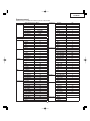
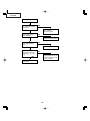
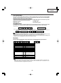
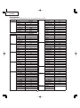
Process menu1
Readjust only the shaded items from the process menu below.
First layer
Adjustment Process Menu
DTV
Pedestal
DVD
VERSION
VIDEO
SS
AD
TEMP
OUTPUT1
PATTERN
OUTPUT2
LAMP
OUTPUT3
LINE
VIDEO1
EXIT
Second layer
DTV
Contrast
Bright
Color
Tint
Sharpness
EXIT
DVD
Contrast
Bright
Color
Tint
Sharpness
EXIT
VIDEO
Contrast
Bright
Color
Tint
Sharpness
H-POS
EXIT
AD
R-Bright
G-Bright
B-Bright
R-Contrast
G-Contrast
B-Contrast
EXIT
OUTPUT1
R1-BLK
R1-GAIN
G1-BLK
G1-GAIN
B1-BLK
B1-GAIN
S-R1-BLK
S-R1-GAIN
S-G1-BLK
S-G1-GAIN
S-B1-BLK
S-B1-GAIN
EXIT
OUTPUT2
Initial Value
45
32
0
5
1
OUTPUT3
46
34
0
5
1
43
142
135
128
3
125
63
63
63
170
170
170
VIDEO1
190
175
190
175
190
175
190
175
190
175
190
175
Pedestal
VERSION
31
PSIG-H
PSIG-L
LC-SW
LC-HPOS-R
RLV1
RLV2
RLV3
LC-HPOS-G
GLV1
GLV2
GLV3
LC-HPOS-B
BLV1
BLV2
BLV3
EXIT
RC
GC
BC
RCK-PHASE
GCK-PHASE
BCK-PHASE
ENBXR-PH
ENBXG-PH
ENBXB-PH
ENBX-WIDTH
DGC-SW
DGCJ-R
DGCJ-G
DGCJ-B
CC
GAMMA
EXIT
NT3.58 Delay
NT4.43 Delay
PAL Delay
SECAM Delay
EXIT
Contrast
Bright
R-Bright
G-Bright
B-Bright
R-Contrast
G-Contrast
B-Contrast
EXIT
Build
Boot Code
Config
140
105
1
2
0
4
0
2
0
4
0
2
0
4
0
128
128
128
282
282
282
13
13
13
4
1
0
0
0
1
1
0
0
0
0
+10
-20
-10
-10
-10
+10
+10
+10
PG-B10S
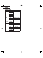
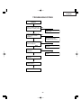
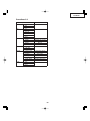
Process menu2
second layer
VERSION
Rom Code
GUI
EXIT
SS
SS2
SS3 EU
SS4 US
SS5 JPN
SS6 CHIN
EXIT
TEMP
Temp1
Temp2
Temp3
Temp4
EXIT
PATTERN
Cross Hatch
Color Bar
EXIT
LAMP
Current Time
History1
History2
History3
History4
TOTAL TIME
EXIT
LINE
OFF
LED CHECK
EXIT
Initial Value
Parameter of sensor 1
Parameter of sensor 2
No Use
No Use
Current time of use
One earlier
Two earlier
Three earlie
Four earlier
Total operating hours
32
PG-B10S
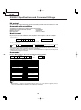
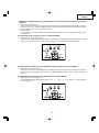
UPGRADING THE VERSION
1) Prepare the RS232C cross cable and conversion cable at hand.
1. Connections
Connect the RS232C cross cable to a computer (Windows98 and higher OS), and the conversion cable to the
set.
2. Do not connect the AC power cord yet at this time.
2) Upgrading procedure
1. For upgrading the PG-B10S, use the "Flash Upgrader" program.
2. Decompress the attached file, and a folder is created.
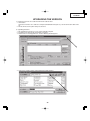
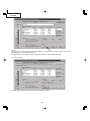
3. Double-click on "FlashUpgrader.exe", and the following window appears
4. Click on the "Choose" button, and the following window appears.
33
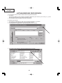
PG-B10S
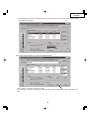
5. Click on the arrow mark shown above, and select the decompressed folder.
6. Select "pwSDK.inf" in the folder.
7. Double-click on "pwSDK.inf".
34
PG-B10S
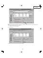
Note:
Do not put checkmark the "Continuous Flash Mode" and "Notify On Completion" boxes, but put checkmark the
"Reset Target After Download" box, all in Options.
Put checkmark the "Flash" box in Modes.
8. Click on "Flash".
The above screen shows up to get ready to write the program.
35
PG-B10S
9. Now connect the AC power cord, and the program will be written. Wait for 4 minutes or so until the writing is
completed.
Do not disconnect the AC cord by at this time . Below windows is underwriting.
With the writing complete, the following screen shows up.
Click on "Close", and the upgrading ends.
The set may or may not get started itself. But disconnect and reconnect the AC power cord, and get the set started.
After up grade, OSD is in Japanese, Background is set None and Eco mode is ON.
So, change OSD is Englis, Background is set to SHARP and Eco mode is off, (Or, set to "SS3". However, lamp time
is also in this case.)
36
PG-B10S
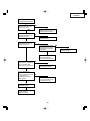
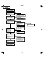
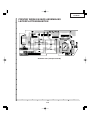
TROUBLESHOOTING
Checking the basic
operation
NO
Does the power LED light
up or flash in red or green?
Go to "Checking the
power unit".
YES
Does the set function with
its keys or the remote
controller?
NO
Go to "Checking the
microprocessor circuits".
YES
Is the cooling fan running
with the lamp on?
NO
Go to "Checking the lamp
light-up".
YES
NO
Is the user menu
displayed?
YES
Go to "Checking the RGB
signals".
Go to "Checking the RGB
isignals".
Go to "Checking the
video signals".
End
37
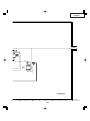
PG-B10S
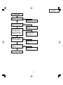
Checking the power unit
Are the P701, P711 and
P741 connectors tightly
connected?
NO
Reconnect the P701,
P711 and P741
connectors tightly.
YES
Is the bimetal switch in
good condition?
NO
YES
Is there AC voltage (100240V) applied across
C701?
Replace the bimetal switch.
NO
Replace F701.
YES
Disconnect the P741
connector. Is there 6V
output at pins (11) and
(12)?
YES
NO
Check IC721, R738, R739
and their peripheral ICs for
damages. Replace any of
them as required.
Check the main PWB for
short-circuit.
38
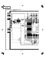
PG-B10S
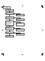
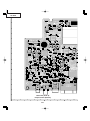
Checking the
microprocessor circuits
Is there about DC3.3V
applied between pins (3)
and (5) of IC1703?
NO
Check IC1703 and its
peripheral circuits, or IC1702
and its peripheral circuits.
YES
Is there about DC2.5V
applied between pins (5)
and (8) of IC1704?
NO
Check IC1704 and its
peripheral circuits.
YES
Is there about DC2.5V
applied between pins (3)
and (4) of IC8009?
NO
Is the lamp cover or filter
cover tightly closed? Or is
the P2006(LF) jack tight
in position?
YES
YES
Close the lamp cover or
filter cover tightly. Or
insert the P2006(LF) jack.
Is there 133-MHz clock
NO
output at pin (6) of IC8010?
Is there 75-MHz clock
output at pin (6) of IC8011?
Check IC8010, IC8011 and
their peripheral circuits.
YES
Is there about DC3V
applied at pin (21) of
IC2002? Check the D0 thru
D7 signals with an
oscilloscope: Are there
pulse signals?
YES
NO
Check the fan for unusual
run. Or check IC8003 and
its peripheral circuits.
Check IC2002 and its
peripheral circuits.
Check IC8202, IC8203,
IC2601 and their
peripheral circuits.
39
NO
Check IC8009 and its
peripheral circuits.
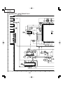
PG-B10S
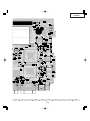
Checking the lamp
light-up
Is the lamp tight in the
socket?
NO
YES
Is there DC350-400V
voltage applied between
the P712 pins?
Insert the lamp tightly in
the socket.
NO
Go to "Checking the
power unit".
YES
Are the P741 and P742
harnesses tightly
connected on both the
power and ballast units?
Or are the harnesses in
good condition?
NO
Insert the P741 and P742
harnesses tightly. Or
replace the harnesses as
required.
YES
Are there 3V (High level)
voltage and over-1V
voltage applied at pins (6)
and (3), respectively, of
P741 on the power unit?
NO
Go to "Checking the
microprocessor circuits".
YES
Is high-pressure noise
heard?
YES
NO
Replace the ballast.
Replace the lamp.
40
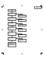
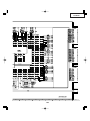
PG-B10S
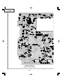
Checking the RGB
signals
Are there RGB gradation
signals at pins (43), (48) and
(54) of IC6004?
NO
Check Q3008, Q3012,
Q3016 and their peripheral
circuits.
YES
Are there RIN2-RIN9,
GIN2-GIN9 and BIN2BIN9 input signals at
IC1401?
NO
Check IC8003 and its
peripheral circuits.
YES
Are there input signals at
pins (70) thru (79) of
IC1101, IC1201 and
IC1301?
YES
Are there input signals at
pins (7) thru (12) of
SC1101, SC1201 and
SC1301?
NO
Check IC1401 and its
peripheral circuits.
NO
Check IC1101, IC1201,
IC1301 and their
peripheral circuits.
YES
Are there input signals at
pins (5) and (25) of
SC1101, SC1201 and
SC1301?
NO
Check IC1101, IC1201,
IC1301 and their peripheral
circuits.
YES
Are there input signals at
pins (6) and (24) of
SC1101, SC1201 and
SC1301?
YES
NO
Check IC1505, IC1501,
IC1503 and their
peripheral circuits.
Check the LCD panel
connections.
If both the video and
onscreen display fail to
appear, replace the LCD
panels.
41
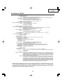
PG-B10S
Checking the S-Video
signals
Is there specified voltage
at the EA connector?
NO
Go to "Checking the
power unit".
YES
Is there S-Video input
signal at pins (71) and (75)
of IC3001?
NO
Check the S-Video
terminal and its peripheral
circuits.
Check IC3001 and its
peripheral circuits.
Checking the Video
signals
Is there specified voltage
at the EA connector?
NO
YES
Is there Video input signal
at pin (73) of IC3001?
YES
Go to "Checking the power
unit".
NO
Check the Video terminal
and its peripheral circuits.
Check IC3001 and its
peripheral circuits.
42
PG-B10S
Technische Daten
Produkttyp LCD-Projektor
Modell PG-B10S
Videosystem NTSC3.58/NTSC4.43/PAL/PAL-M/PAL-N/PAL-60/SECAM/
DTV480I/DTV480P/DTV540P/DTV580I/DTV580P/DTV720P/DTV1035I/DTV1080I/DTV1080I-50
Anzeigeverfahren LCD-Panel × 3, optische RGB-Verschlussmethode
LCD-Panel Panel-Größe: 0,55 tum (14,0 mm) (8,5 [H] × 11,2 [B] mm)
Anzahl der Bildpunkte: 480.000 Bildpunkte (800 [H] × 600 [V])
Objektiv 1–1,25 × Zoom-Objektiv, F1,6–1,9, f = 16,8–20,9 mm
Projektionslampe Wechselstromlampe 130 W
Eingangs-/Ausgangssignal-Komponente 15-Pin-Mini-D-Sub-Anschluss
(INPUT 1) Y: 1,0 Vp-p, negatives Sync., 75 terminiert
PB: 0,7 Vp-p, 75 terminiert
PR: 0,7 Vp-p, 75 terminiert
Horizontale Auflösung 520 Fernsehzeilen (DTV 720P)
Computer-RGB-Eingangs-/Ausgangssignal 15-Pin-Mini-D-Sub-Anschluss
(INPUT 1) RGB getrennt/Sync. auf Grün-Typ analoger Eingang: 0-0,7 Vp-p, positiv, 75 terminiert
HORIZONTALES SYNC.-SIGNAL: TTL-Pegel (positiv/negativ)
VERTIKALES SYNC.-SIGNAL: Wie oben
S-Videoeingangssignal 4-pin-Mini-DIN-Anschluss
(INPUT 2) Y (Luminanzsignal): 1,0 Vp-p, negatives Sync., 75 terminiert
C (Chrominanzsignal): Stoß 0,286 Vp-p, 75 terminiert
Videoeingangssignal RCA-Anschluss: VIDEO, Verbund-Video, 1,0 Vp-p, negatives Sync., 75 terminiert
(INPUT 3)
Computer-Steuerungssignal (RS-232C) 9-Pin-Mini-DIN-Stecker
Pixeltakt 12-108 MHz
Vertikale Frequenz 43-85 Hz
Horizontale Frequenz 15-70 kHz
Audioeingangssignal ø 3,5 mm-Minibuchse: AUDIO, 0,5 Vrms, mehr als 22 k (Stereo)
Audioausgang 1,0 W (Mono)
Lautsprechersystem 2,8 cm rund × 1
Nennspannung 100-240 V Wechselstromspannung
Eingangsstrom 1,9 A
Nennfrequenz 50/60 Hz
Leistungsaufnahme 185 W (Standard-Modus)/170 W (Eco-Modus) bei AC 100 V
175 W (Standard-Modus)/160 W (Eco-Modus) bei AC 240 V
Leistungsaufnahme 4 W (bei AC 100 V)-6 W (bei AC 240 V)
(Bereitschaft) 695 BTU/Stunde (Standard-Modus)/640 BTU/stunde (Eco-Modues) bei AC 100 V
Wärmeableitung 660 BTU/Stunde (Standard-Modus)/600 BTU/stunde (Eco-Modues) bei AC 240 V
Betriebstemperatur 41°F bis 95°F (+5°C bis +35°C)
Lagertemperatur – 4°F bis 140°F (–20°C bis +60°C)
Gehäuse Plastik
I/R-Trägerfrequenz 38 kHz
Abmessungen (ca.) 11 37/64" × 3 5/8" × 8 3/4" (294 (B) × 92 (H) × 222 (T) mm) (nur Hauptgerät)
11 39/64" × 4 11/64" × 9 11/32" (294,5 (B) × 105,8 (H) × 237 (T) mm) (einschließlich Einstellfüße und
Projektionsteile)
Gewicht (ca.) 6,0 lbs. (2,7 kg)
Mitgeliefertes Zubehör Fernbedienung, zwei R6-Batterien, Netzkabel für USA, Kanada usw. (6', 1,8 m), Netzkabel für Europa, außer
Großbritannien (6', 1,8 m), Netzkabel für Großbritannien, Hongkong und Singapur (6', 1,8 m), Netzkabel für Australien,
Neuseeland und Ozeanien (6', 1,8 m), RGB-Kabel (9' 10", 3,0 m), Tragetasche, Objektivkappe (befestigt), zusätzlicher
Luftfilter, Versandverpackung der Linse (befestigt), Projektorhandbuch- und technische Referenz-CD-ROM, “QUICK
GUIDE (Schnellanleitung)”-Aufkleber, Bedienungsanleitung
Ersatzteile Lampeneinheit (Lampen-/Gehäusemodul) (BQC-PGB10S//1), Fernbedienung (RRMCGA187WJSA), zwei R 6-Batterien
(“AA”, UM/SUM-3, HP-7 oder entsprechend), Netzkabel für USA, Kanada usw. (QACCDA016WJPZ), Netzkabel für Europa,
außer Großbritannien (QACCVA006WJPZ), Netzkabel für Großbritannien, Hongkong und Singapur (QACCBA015WJPZ),
Netzkabel für Australien, Neuseeland und Ozeanien (QACCLA005WJPZ),RGB-Kable (QCNWGA012WJPZ), Tragetasche
(GCASNA009WJSA), Objektivkappe (CCAPHA004WJ01), Luftfilter (PFILDA010WJZZ), Versandverpackung der Linse
(SPAKXA333WJZZ), Projektorhandbuch- und- technische Referenz-CD-ROM (UDSKAA039WJZZ), “QUICK GUIDE
(Schnellanleitung)”-Aufkleber (TLABZA439WJZZ), Bedienungsanleitung (TINS-A917WJZZ)
Bedingt durch fortlaufende technische Verbesserungen behält sich SHARP das Recht vor, das Design und die Spezifikationen ohne vorherige Ankündigung ändern zu können. Die angegebenen
Leistungswerte stellen die Nennwerte einer in Serienherstellung produzierten Einheit dar. Geringe
Abweichungen bei einzelnen Geräten sind möglich.
43
PG-B10S
HINWEISE FÜR DAS
WARTUNGSPERSONAL
123456789012345678901234567890121234567890123456
123456789012345678901234567890121234567890123456
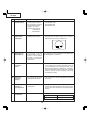
ACHTUNG: UV-STRAHLUNG
123456789012345678901234567890121234567890123456
123456789012345678901234567890121234567890123456
Die Beleuchtungsquelle des LCD-Projektors, eine
UHP-Lampe, emittiert eine geringe Menge
UV-Strahlung.
DIREKTE BESTRAHLUNG AUF AUGEN
UND HAUT MUSS VERMIEDEN WERDEN.
Zur Gewährleistung der Sicherheit muß folgendes
beachtet werden:
Auswechseln der Lampe
Hinweis:
Da die Lampe während des Betriebs sehr heiß wird, sollte
die Lampe erst ausgewechselt werden, nachdem das
Gerät mindestens eine Stunde ausgeschaltet war, damit
die Lampe ausreichend abkühlen kann.
Beim Installieren der neuen Lampe muß darauf
geachtet werden, die Lampe selbst (Glaskolben)
nicht zu berühren. Vielmehr muß die Lampe am
Reflektor 2 gehalten werden.
[Es darf nur ein Original-Ersatzteil verwendet
werden.]
1 Lampe
1. Bei Arbeiten am Projektor bei eingeschalteter
Lampe und abgenommenem oberen Gehäuse muß
unbedingt eine Sonnenbrille getragen werden.
2 Reflektor
GEFAHR! — Niemals die Spannungsversorgung
einschalten, ohne daß eine Lampe vorhanden ist, um
elektrische Schläge und Schäden am Gerät zu
vermeiden, da der Stabilisator anfangs hohe
Spannungen erzeugt.
2. Die Lampe darf nicht außerhalb des
Lampengehäuses eingeschaltet werden.
Da eine geringe Menge UV-Strahlung an der Öffnung
zwischen den Lüftern austritt, wird empfohlen, während
der Wartungsarbeiten die Abdeckkappe des Zusatzobjektivs an dieser Öffnung anzubringen, um Augen
und Haut vor den UV-Strahlen zu schützen.
3. Betrieb für länger als 2 Stunden bei
abgenommenem Gehäuse ist nicht zulässig.
Zur Beachtung bei UV-Strahlung
und Mitteldruck-Lampen
1. Vor dem Auswechseln der Lampe muß der Netzstecker
gezogen werden.
2. Vor Durchführung von Wartungsarbeiten muß das
Gerät eine Stunde abkühlen.
3. Die Lampe darf nur gegen eine der gleichen Art
ausgewechselt werden. Typ BQC-PGB10S//1,
bemessen für 100V/130W.
4. Die Lampe gibt eine geringe UV-Strahlung ab, daher
muß direkter Augenkontakt vermieden werden.
5. Die Mitteldruck-Lampe weist ein Explosionsrisiko auf.
Daher müssen die nachstehenden
Installationsanweisungen beachtet werden, und die
Lampe muß vorsichtig behandelt werden.
44
PG-B10S
Vorsichtsmaßregeln für bleifreien Lötzinn
1 Verwendung von bleifreiem Lötzinn
Bei den Platinen für dieses Modells wird bleifreies Lot verwendet. Das Symbol LF kennzeichnet bleifreies Lot und
findet sich an den Platinen und in den Wartungshandbüchern. Der Buchstabe hinter LF bezieht sich auf die Art des
bleifreien Lots.
Beispiel:
LFa
Zeigt bleifreien Lötzinn aus Zinn, Silber und Kupfer an.
2 Bei Reparatur der mit bleifreiem Lötzinn gelöteten Platine immer bleifreien Lötzinn verwenden. Reparatur mit
herkömmlichem Lötzinn kann zu Schäden oder Unfällen aufgrund von Rissen führen.
Da der Schmelzpunkt bleifreien Lvtzinns (Sn-Ag-Cu) um 40°C höher als der von Bleidraht-Lötzinn ist, empfehlen
wir die Verwendung einer speziellen Lötspitze. Wenn Fragen über den Beschaffung leitfreien Lötzinns oder spezieller
Lötspitzen bestehen, wenden Sie sich an unsere Kundendienstvertretung in Ihrem Gebiet.
3 Löten
Da der Schmelzpunkt bleifreien Lötzinns (Sn-Ag-Cu) etwa 220°C beträgt, was um 40°C höher als der von bleihaltigem
Lötzinn ist, und außerdem schlechte Löt-Benetzbarkeit aufweist, kann es erforderlich werden, die Lötspitze längere
Zeit in Kontakt mit der Platine zu halten. Da die Lötlauge abfliessen kann oder der maximale Hitzewiderstand von
Teilen überschritten werden kann, die Lötspitze sofort von der Platine nehmen, sobald eine gute Lötung erzielt ist.
Bleifreier Lötzinn enth_lt mehr Zinn, und das Ende der Lötspitze kann leicht angegriffen werden. Immer sicherstellen,
dass der Lötkolben nur bei Bedarf eingeschaltet wird.
Wenn ein anderer Typ von Lötzinn an der Lötspitze haften bleibt, verschmilzt er mit dem bleifreien Lötzinn. Die
Lötspitze nach jeder Verwendung reinigen.
Wenn die Lötspitze bei der Verwendung geschwärzt wird, die Spitze mit Stahlwolle oder feinem Sandpapier
abschmirgeln.
Immer beim Austausch von Teilen vorsichtig sein, und die Polaritätsanzeige auf der Platinenbeschriftung beachten.
Bleifreier Lötzinn zur Wartung
Teile-Nr.
ZHNDAi123250E
ZHNDAi126500E
ZHNDAi12801KE
★
J
J
J
Beschreibung
φ0.3mm
250g(1roll)
φ0.6mm
500g(1roll)
φ1.0mm
1 Rolle
45
Code
BL
BK
BM
PG-B10S
Bedienungsanleitung
Projektor (Vorderansicht- und Draufsicht)
INPUT-Taste
ON-Taste
Für das Umschalten zwischen
Eingang 1, 2 oder 3-Betriebsart.
Schaltet die Stromversorgung ein.
Netz-Anzeige
KEYSTONE-Taste
Für das Aktivieren des
Trapezverzerrungs-Korrekturmodus.
STANDBY-Taste
Einstelltasten (', ", \, |)
Schaltet den Projektor in den
Standby-Modus.
• Für die Auswahl der Menüpunkte .
• FürTrapezkorrektur, wenn Sie sich
imTrapezverzerrungsKorrekturmodus befinden.
Lampen-Anzeige
Lautstärke-Tasten
Temperaturwarn-Anzeige
Für das Einstellen des
Lautsprecher-Tonpegels.
AUTO SYNC-Taste
Für das automatische Einstellen
von Bildern, wenn ein Computer
angeschlossen ist.
ENTER-Taste
Für das Einstellen der
ausgewählten oder eingestellten
Menüpunkte .
MENU-Taste
Für die Anzeige des Justierungsund Einstellungsbildschi rms.
Fernbedienungssensor
Fokusring
Zoom-Knopf
Einsaugöffnung
Lautsprecher
Lens-Shift-Hebel
Vorderer Einstellfuß
(auf der Unterseite des
Projektors)
HEIGHT ADJUST-Taste
Anbringen und Abnehmen der
Objektivkappe
• Drücken Sie an den beiden Tasten der
Objektivkappe, und bringen Sie diese
am Objektiv an. Lassen Sie die Tasten
anschließend los, um die Objektivkappe
zu verriegeln.
• Drücken Sie die beiden Tasten der
Objektivkappe und nehmen Sie die
Objektivkappe vom Objektiv ab.
46
PG-B10S
Informationen über die Anzeigen des Projektors
Netz-Anzeige
Grün ein/Rot ein ... Normal
Rot blinkt ... Unnormal
Lampen-Anzeige
Grün ein ... Normal
Grün blinkt ...Die Lampe wird aufgewärmt.
Rot ein ... Wechseln Sie die Lampe.
Temperaturwarn-Anzeige
Aus ... Normal
Rot ein ...Die Temperatur im Inneren des Gerätes ist
zu hoch.
Befestigen und Entfernen der Versandpackung
der Linse
Wenn Sie die Versandpackung der Linse befestigen, vergewissern
Sie sich, dass der Umstellhebel der Linse auf die mittlere Position
eingestellt ist. Wird die Linse nach oben oder unten gestellt, kann die
Versandverpackung nicht befestigt werden.
47
PG-B10S
Projektor (Hintersicht)
INPUT 1-Anschluss
INPUT 2-Anschluss
Anschluss für ComputerRGB- und
Komponentensignale.
Anschluss für ein
Videogerät mit einem
S-VIDEO-Anschluss.
RGB AUSGABEAnschluss
INPUT 3-Anschluss
Anschluss für ein
Videogerät.
Terminal zum Anschluss
eines Monitors.
RS-232C-Anschluss
AUDIO INPUTAnschluss
Anschluss für die Bedienung
des Projektors unter
Verwendung eines
Computers.
Geteilter
Audioeingabeanschluss
für INPUT 1, 2 und 3.
Luftaustrittöffnung
Hinterer Einstellfuß
(auf der Unterseite
des Projektors)
Netzanschluss
KensingtonSicherheitsstandardanschlus
Verwendung der Kensington-Sperre
• Dieser Projektor ist mit einem Kensington-Sicher-heitsstandardanschluss für die Verwendung des Kensington
MicroSaver-Sicherheits-systems ausgestattet. Lesen Sie hinsichtlich dessen Verwen-dung die Informationen,
die dem System beiliegen, um den Projektor zu sichern.
48
PG-B10S
EINGABE/AUSGABE Terminals und Hauptausrüstung
zum Anschließen
RS-232C-Anschluss
Anschluss des Computers
zur Steuerung des
Projektors.
INPUT 1-Anschluss
Anschließen des Computers.
INPUT 3-Anschluss
Anschließen der Videogeräte ohne
S-Video Ausgabeterminal.
Anschließen der Videogeräte
mit der Komponente
Ausgabeterminal (DVDPlayer, DTV-Decoder, usw.).
AUDIO INPUT-Anschluss
RGB AUSGABEAnschluss
Anschließen des Monitors,
wenn Sie das
Projektionsbild gleichzeitig
auf dem Bildschirm sehen
möchten.
INPUT 2-Anschluss
Anschließen der Videogeräte mit
S-Video Ausgabeterminal
(Videorecorder, Laser Disc-Player,
usw.).
49
Anschließen an ein
Tonabnehmerkabel
(Gemeinsames AudioEingabeterminal für INPUT 1,
2 und 3).
PG-B10S
Fernbedienung (Vordersicht)
ON-Taste
STANDBY-Taste
Schaltet die Stromversorgung ein.
Schaltet den Projektor in den
Standby-Modus.
MENU-Taste
KEYSTONE-Taste
Für die Anzeige des Justierungs- und
Einstellungsbildschirms.
Für das Aktivieren des TrapezverzerrungsKorrekturmodus.
Einstelltasten ('" \ |)
• Für die Auswahl der Menüpunkte.
• Für Trapezkorrektur, wenn Sie sich im
Trapezverzerrungs-Korrekturmodus
befinden.
UNDO-Taste
Für das Rückgängigmachen eines
Bedienschrittes oder für die Rückkehr zur
vorherigen Anzeige.
FORWARD/BACK-Tasten
ENTER-Taste
Gleiche Funktion wie die [Page Down]- und
[Page Up]-Tasten auf der ComputerTastatur, wenn der optionale
Fernbedienungsempfänger (AN-MR1EL)
verwendet wird.
Für das Einstellen der ausgewählten oder
eingestellten Menüpunkte.
FREEZE-Taste
Für das Einfrieren von Bildern.
ENLARGE-Tasten
(Vergrößern/Verkleinern)
AV MUTE-Taste
Für das Vergrößern oder Verkleinern eines
Bildteils.
Für die vorübergehende Anzeige des
Schwarzbildschirms und das
vorübergehende Ausschalten des Tons.
AUTO SYNC-Taste
Für das automatische Einstellen
von Bildern, wenn ein Computer
angeschlossen ist.
RESIZE-Taste
Für das Umschalten der Bildwandgröße
(NORMAL, UMRANDUNG usw).
INPUT-Tasten
Für das Umschalten auf die
entsprechenden Eingangs-Betriebsart.
Lautstärke-Tasten
Für das Einstellen des LautsprecherTonpegels.
50
PG-B10S
Pin-Belegung
Reichweite
Fernbedienungssensor
Der Projektor kann mittels der Fernbedienung
innerhalb der in der Abbildung dargestellten
Bereiche gesteuert werden.
30°
Hinweis
30°
• Das Signal von der Fernbedienung kann für eine
einfache Bedienung von der Bildwand reflektiert
werden. Die tatsächliche Reichweite des Signals
kann je nach Bildwandmaterial unterschiedlich sein.
Signalsender für
Fernbedienung
30°
23' (7 m)
Bei Verwendung der Fernbedienung:
• Nicht fallen lassen, keiner Feuchtigkeit oder hohen
Temperatur aussetzen.
• Die Fernbedienung funktioniert unter Umständen
Fernbedienung
nicht unter einer Fluoreszenzlampe. Unter diesen
Umständen
den
Projektor
von
der
Fluoreszenzlampe entfernt aufstellen.
Einlegen der Batterien
Die Batterien (zwei R 6-Batterien (“AA”, UM/
SUM-3, HP-7 oder entsprechend)) sind in der
Packung enthalten.
1
Auf die -Markierung auf der
Abdeckung drücken und in
Pfeilrichtung schieben.
2
Die Batterien einlegen.
• Die Batterien einlegen und sicherstellen,
und
dass die Pole mit den Markierungen
im Batteriefach übereinstimmen.
3
Die Abdeckung anlegen und
schieben, bis sie einrastet.
Falsche Verwendung der Batterien kann eine Leckage oder Explosion zur Folge haben. Bitte befolgen
Sie die unten stehenden Vorsichtsmaßnahmen.
Achtung
• Die Batterien einlegen und sicherstellen, dass die Pole mit den Markierungen
und
im Batteriefach übereinstimmen.
• Batterien unterschiedlichen Typs haben unterschiedliche Eigenschaften, verwenden Sie deshalb keine Batterien
unterschiedlichen Typs zusammen.
• Verwenden Sie keine neuen und alten Batterien zusammen.
Dadurch könnte die Lebensdauer der neuen Batterien reduziert oder ein Auslaufen der Batterien verursacht werden.
• Nehmen Sie leere Batterien aus der Fernbedienung heraus, da sie ansonsten auslaufen könnten.
Aus den Batterien ausgelaufene Batterieflüssigkeit ist für Ihre Haut schädlich, wischen Sie die Batterien deshalb unbedingt
zuerst ab und nehmen Sie sie dann mit einem Tuch heraus.
• Die diesem Projektor beiliegenden Batterien können unter Umständen, je nach Handhabung, nach kurzer Zeit
aufgebraucht sein. Stellen Sie sicher, dass sie so bald wie möglich durch neue Batterien ersetzt werden.
• Nehmen Sie die Batterien heraus, wenn die Fernbedienung lange nicht verwendet wird.
51
PG-B10S
INPUT 1 und RGB AUSGABE-Signalanschluss: 15-Pin Mini-D-Sub weiblich
RGB-Eingang
10
5
6
1
15
11
1.
2.
3.
4.
5.
6.
7.
8.
9.
10.
11.
12.
13.
14.
15.
Komponenteneingang
Videoeingang (rot)
Videoausgang (grün/Sync. auf grün)
Videoausgabe (blau)
Nicht angeschlossen
Nicht angeschlossen
Erde (rot)
Erde (grün/Sync. auf grün)
Erde (blau)
nicht angeschlossen
GND
Nicht angeschlossen
Bi-direktionale Daten
Horizontal-Sync-Signal: TTL-Pegel
Vertikal-Sync-Signal: TTL-Pegel
Datentakt
1.
2.
3.
4.
5.
6.
7.
8.
9.
10.
11.
12.
13.
14.
15.
PR (CR)
Y
PB (CB)
Nicht angeschlossen
Nicht angeschlossen
Erde (PR)
Erde (Y)
Erde (PB)
Nicht angeschlossen
Nicht angeschlossen
Nicht angeschlossen
Nicht angeschlossen
Nicht angeschlossen
Nicht angeschlossen
Nicht angeschlossen
RS-232-Anschluss: 9-Pin Mini-DIN weiblich
8
9
7
6
3
Pin-Nr.
1
2
3
4
5
6
7
8
9
Signal
Name
I/O
RD
SD
Daten empfangen
Daten senden
SG
Signalerde
Eingang
Ausgang
RS
CS
Referenz
Nicht angeschlossen
Interner Stromkreisanschluss
Interner Stromkreisanschluss
Nicht angeschlossen
Interner Stromkreisanschluss
Nicht angeschlossen
Angeschlossen an Pin 8
Angeschlossen an Pin 7
Nicht angeschlossen
4
5
2
1
DIN-D-sub RS-232C Adaptor: 9-pin D-sub männlicher Stecker
1
6
5
9
Pin-Nr.
1
2
3
4
5
6
7
8
9
Signal
Name
I/O
RD
SD
Daten empfangen
Daten senden
SG
Signalerde
Eingang
Ausgang
RS
CS
Referenz
Nicht angeschlossen
Interner Stromkreisanschluss
Interner Stromkreisanschluss
Nicht angeschlossen
Interner Stromkreisanschluss
Nicht angeschlossen
Interner Stromkreisanschluss
Interner Stromkreisanschluss
Nicht angeschlossen
Hinweis
• Pin 8 (CS) und Pin 7 (RS) sind im Innern des Projektors kurzgeschlossen.
RS-232C Kabel empfohlene Verbindung: 9-Pin-D-Sub weiblich
5
9
1
6
Pin-Nr.
1
2
3
4
5
6
7
8
9
Signal
CD
RD
SD
ER
SG
DR
RS
CS
CI
Pin-Nr.
1
2
3
4
5
6
7
8
9
Signal
CD
RD
SD
ER
SG
DR
RS
CS
CI
Hinweis
• Je nach verwendetem Steuergerät ist es unter Umständen erforderlich, Pin 4 und Pin 6 am Steuergerät (z.B.
am PC) anzuschließen.
Projektor
Pin-Nr.
4
5
6
PC
Pin-Nr.
4
5
6
52
PG-B10S
PC-Steuerung
Der Projektor kann durch einen Anschluss an einen Computer über ein serielles RS-232C-Steuerkabel
(Kreuztyp, separat erhältlich) über den Computer gesteuert werden. (Siehe Seite 54 Anschlussanleitungen.)
Kommunikationsbedingungen
Legen Sie die seriellen Porteinstellungen des Computers so fest, dass sie denen der Tabelle entsprechen.
Signalformat: Entspricht dem RS-232C-Standard.
Paritätsbit: Keine
Baud-Rate: 9.600 Bps
Stopp-Bit: 1 Bit
Datenlänge: 8 Bit
Flusssteuerung: Keine
Grundformat
Computerbefehle werden in folgender Reihenfolge gesendet: Befehl, Parameter und Rückcode. Nachdem
der Projektor den Computerbefehl ausgeführt hat, sendet er einen Antwortcode an den Computer.
Befehlsformat
C1 C2 C3 C4 P1 P2 P3 P4
Befehl 4-stellig
Antwortcodeformat
Normalantwort
O
K
Rückcode (0DH)
Parameter 4-stellig
Problemantwort (Kommunikationsfehler oder inkorrekter Befehl)
Rückcode (0DH)
E
R
R
Rückcode (0DH)
Info
• Wenn Sie den Projektor mit Hilfe einer RS-232C Steuerung eines Computers bedienen, warten Sie nach
dem Einschalten des Gerätes mindestens 30 Sekunden, bevor Sie die Befehle übertragen.
• Wird mehr als ein Code gesendet, dann wird jeder Befehl erst nach der Verifizierung des Empfangs der
Antwort für den vorangegangenen Befehl vom Projektor gesendet.
Befehle
Beispiel: Wenn der Projektor eingeschaltet wird, folgende Einstellung durchführen:
Projektor
Computer
P
O
W
R
_
TASTEN- UND FERNBEDIENUNGSSCHLÜSSEL
STEUERUNGSINHALTE
_
BEFEHL
_
1
PARAMETER
Bereitschaft
P O W R _ _ _ 0 OK oder ERR
Strom Ein
P O W R _ _ _ 1 OK oder ERR
EINGANG 1
I R G B _ _ _ 1 OK oder ERR
EINGANG 2
I V E D _ _ _ 1 OK oder ERR
EINGANG 3
I V E D _ _ _ 2 OK oder ERR
EINGANG 1 Signaltyp: Auto
I A S I _ _ _ 0 OK oder ERR
I A S I _ _ _ 1 OK oder ERR
EINGANG 1 Signaltyp: RGB
O
RÜCKCODE
EINGANG 1 Signaltyp: Komponente
I A S I _ _ _ 2 OK oder ERR
Lampen-Betriebsdauer (Stunden)
Verbleibende Lampen-Lebensdauer (Prozent)
T L T T _ _ _ 1 0~9999
T L T L _ _ _ 1 0~100
Lampenstatus
T L P S _ _ _ 1 0:Aus, 1:Ein, 2:Neuversuch, 3:Warten, 4:Lampenfehler
Gerätestatus
T A B N _ _ _ 1 0: Normal, 1: Hohe Temp., 2: Gebläsefehler,
4: Filter oder Lampenabdeckungs-Fehler,
8: Lampen-Lebensdauer 5 % oder weniger,
16: Lampe ausgebrannt, 32: Lampe leuchtet nicht,
64: Temp. unnormal hoch
Modellnamen-Prüfung
T N A M _ _ _ 1 PROJEKTORNAME
AV-Stmhalt Aus
I M B K _ _ _ 0 OK oder ERR
AV-Stmhalt Ein
I M B K _ _ _ 1 OK oder ERR
Auto-Sync-Start
A D J S _ _ _ 1 OK oder ERR
K
Hinweis
• Wenn in der Tabellensparte Parameter ein Unterstrich (_) erscheint, geben Sie bitte ein Leerzeichen ein.
Wenn ein Stern (*) erscheint, geben Sie einen Wert innerhalb der in Klammern unter
STEUERUNGSINHALTE angegebenen Spanne ein.
53
PG-B10S
ABMESSUNGEN
Ansicht
von hinten
Einheiten: Zoll (mm)
Ansicht von
oben
Ansicht von
der Seite
Ansicht von
der Seite
2 1/4 (57)
8 9/64 (206.5)
1 45/64 (43.2) 1 59/64 (48.8)
3 5/8 (92)
Ansicht von
vorne
2 17/32 (64)
1 31/32 (49.7)
ø 65
7 15/32 (189.5)
19/32 (15)
8 3/4 (222)
11 37/64 (294)
2 25/64 (60.4)
2 17/32 (64.2)
7 45/64 (195.6)
3 27/64 (86.6)
8 11/64 (207.4)
7 43/64 (194.5)
Ansicht von
unten
2 9/16 (65)
3 59/64 (99.5)
1 61/64 (49.5)
1 1/8 (28.5)
1 25/32 (45)
Einheit:mm
54
PG-B10S
ENTFERNEN DER HAUPTTEILE
1. Entfernen der Lampeneinheits- und der Filtereinheitsabdeckung
1-1. Die Sicherungsschraube von der Lampeneinheitsabdeckung losdrehen, dann die Lampeneinheitsabdeckung
entfernen.
1-2. Die beiden Sicher ungsschrauben von der Lampeneinheitsabdeckung losdrehen, dann die
Lampeneinheitsabdeckung entfernen.
1-3. Die beiden Sicherungsschrauben von der Filterabdeckung losdrehen, dann die Filterabdeckung entfernen.
Filterabdeckung
Lampeneinheit
1-2
1-3
Luftfilter
1-2
Lampeneinheitsabdeckung
1-1
2. Entfernen des vorderen und oberen Gehäuseteils
2-1. Die sieben Arretierschrauben vom vorderen und oberen Gehäuseteil losdrehen.
2-2. Die rechte Seite des oberen Gehäuseteils anheben, dann die Haken vorne und links am oberen Gehäuseteil
aushaken. Danach das obere Gehäuseteil abnehmen.
2-3. Die pfeilmarkierten Haken aushaken, dann das vordere Gehäuseteil abnehmen.
Haken
Oberes Gehäuseteil
2-1
Haken
2-2
Vorderes Gehäuseteil
2-3
2-3
2-2
55
PG-B10S
3. Entfernen der Hauptplatine
3-1. Die beiden Sicherungsschrauben von der Hauptplatineneinheit losdrehen, dann die Hauptplatineneinheit
entfernen.
Hauptplatine
[FD]
[EA]
[RP]
[GP]
[RP]
[FA]
[TH]
[FB]
[LF]
[TI] [SP]
3-1
4. Entfernen des Objektivs
4-1. Die beiden Arretierschrauben von der Lampenfassung losdrehen, dann die Lampenfassung abnehmen.
4-2. Die Arretierschraube vom Bimetall losdrehen und das Bimetall entfernen.
4-3. Die fünf Arretierschrauben von der Optikeinheit losdrehen, dann die Optikeinheit, die Seitenblende und die
Isolationsplatine entfernen.
4-1
Lampenfassung
4-2
Bimetall
4-3
4-3
Optikeinheit
Isolationsplatine
4-3
Seitenblende
56
PG-B10S
5. Entfernen der Stromversorgungsplatinen-Vorschaltgeräteeinheit
5-1. Die vier Sicherungsschrauben von der Stromversorgungsplatinen-Vorschaltgeräteeinheit losdrehen, dann
die Platinen-Vorschaltgeräteeinheit entfernen.
5-2. Die Isolationsplatte entfernen.
5-3. Das Platinen-Vorschaltgerät entfernen.
5-1
Stromversorgungsplatine
Obere Abschirmung
5-2
Platinen-Vorschaltgerät
5-3
Untere Abschirmung
5-1
57
PG-B10S
6. Entfernen des Netzeingangs, des Luftauslaßgebläses, des Lautsprechers
sowie des Ansaugschachts und des Ansauggebläses
6-1.
6-2.
6-3.
6-4.
6-5.
Die Netzeingangsplatine entfernen.
Die Sicherungsschraube vom Abluftgebläse losdrehen, dann das Abluftgebläse entfernen.
Den Lautsprecher entfernen.
Die beiden Sicherungsschrauben vom Ansaugschacht losdrehen, dann den Ansaugschacht entfernen.
Das Ansaugschacht entfernen.
Ansaugschacht 6-4
Abluftgebläse
Blattschalter
Netzeingangsplatine
Ansauggebläse
Lautsprecher
Unteres Gehäuseteil
58
PG-B10S
RÜCKSTELLEN DES LAMPENBETRIEBSZEIT-TIMERS
● Rückstellung des Lampen-Timers
Den Lampen-Timer nach dem Lampenaustausch zur ü ckzustellen.
Den Lampen-Timer nach dem Lampenaustausch zurückzustellen.
1
Das Netzkabel anschließen.
2
Den Lampen-Timer zurückstellen.
• Das Netzkabel am Netzanschluss des
Projektors anschließen.
Netzanschluss
• Während
und
ON-Taste
auf dem
Projektor gleichzeitig gedrückt werden,
und
auf dem Projektor drücken.
• “LAMP 0000H” erscheint und zeigt damit an,
dass der Lampen-Timer zurückgestellt wurde.
Taste
Info
• Stellen Sie sicher, dass Sie den Lampen-Timer
nur nach dem Austausch der Lampe zurücksetzen.
Wenn Sie den Lampen-Timer zurückstellen und
dieselbe Lampe weiterhin verwenden, könnte die
Lampe beschädigt werden oder explodieren.
AUTO SYNCTaste
■ Die Warnleuchten auf dem Projektor weisen auf Fehlfunktionen im Projektor hin.
■ Falls ein Problem auftritt, leuchtet entweder dieTemperaturwarn-Anzeige oder die LampenaustauschAnzeige rot auf, und die Stromversorgung wird ausgeschaltet. Nach dem Ausschalten des Gerätes die
unten aufgeführten Verfahren befolgen.
Wartungsanzeige
Unnormal
Normal
TemperaturwarnAnzeige
Aus
LampenAnzeige
Grün ein
Grün blinkt,
wenn die
Lampe
aufgewärmt
wird.
NetzAnzeige
Grün ein /
Rot ein
Symptom
Die Temperatur
Rot ein/
im Inneren des
Bereitschaft Gerätes ist zu
hoch.
Rot ein
Die Lampe muss
ausgetauscht
werden.
Problem
Mögliche Abhilfe
Lüftungsöffnungen
blockiert.
Den Projektor an einem besser
belüfteten Ort aufstellen.
Reinigen Sie den Luftfilter des Projektors.
Kühlventilator beschädigt
Interne Schaltkreise
beschädigt
Lüftungsöffnungen
verstopft
Den Projektor einem von Sharp
autorisierten Händler für Projektoren oder
dem Kundendienst zur Reparatur geben.
Restliche Lebensdauer
der Lampe sinkt auf 5%
oder weniger ab.
Die Lampe
Rot ein/
Bereitschaft leuchtet nicht.
Ausgebrannte Lampe
Lampen-Schaltkreis
beschädigt
Die Netz-Anzeige
Rot blinkt blinkt bei
eingeschaltetem
Projektor rot auf.
Die Filterabdeckung
oder die Abdeckung
der Lampaeneinheit
ist geöffnet.
Lüftungsöffnungen.
Den Projektor einem von Sharp autorisierten
Händler für Projektoren oder dem
Kundendienst zur Reparaturgeben.
Beim Austausch der Lampe bitte die nötige
Vorsicht walten lassen.
Die Abdeckung sicher befestigen.
Wenn die Stromanzeige rot blink, obwohl die
Filterabdeckung und die Abdeckung der
Lampeneinheit ordnungsgemäß eingebaut
wurden, nehmen Sie Kontakt mit einem von
Sharp autorisierten Händler für Projektoren
oder dem Kundendienst in Ihrer Nähe auf.
■ Austausch des Luftfilters
" Ansicht von unten
• Um optimale Arbeitsbedingungen für den Projektor zu
gewährleisten, wurde das Gerät mit einem Luftfilter
ausgestattet.
• Die Luftfilter sollten jeweils nach 100 Betriebsstunden
gereinigt werden. Falls der Projektor in einer sehr
staubigen oder verrauchten Umgebung verwendet wird,
sollten die Luftfilter öfters gereinigt werden.
• Wenn sich der Luftfilter nicht mehr reinigen lässt, wenden
Sie sich bitte an Ihren hinsichtlich eines Ersatzfilters
(PFILDA010WJZZ) an einen von Sharp autorisierten
Händler für Projektoren oder an den Kundendienst.
" Ansicht von vorne
Luftfilter (Herausnehmbar)
4
Den Luftfilter abnehmen.
5
Luftfilter reinigen.
6
Den Luftfilter wieder einsetzen.
7
Ersetzen Sie die Filterabdeckung.
Luftfilter
(nicht abnehmbar)
• Nehmen Sie den Luftfilter mit den
Händen hoch und heben Sie ihn aus der
Filterabdeckung.
• Den Staub auf dem Luftfilter und der
Abdeckung mit einem Staubsaugeraufsatz
entfernen.
STANDBY-Taste
Reinigung und Austausch
des Luftfilters
1
STANDBY
STANDBYTaste
Drücken Sie
auf dem
STANDBY
Projektor oder
auf der
Fernbedienung, um den
Projektor in den Standby-Modus
zu schalten.
• Bringen Sie den Luftfilter unterhalb den
auf den Filterabdeckungen befindlichen
Platten an.
• Warten, bis die Kühlung abschaltet.
2
Das Netzkabel abtrennen.
• Das Netzkabel vom Netzanschluss
abtrennen.
Netzanschluss
1
3
BenutzerWartungsschraube
• Richten Sie die Platte der
Filterabdeckung aus schließen Sie sie
durch Drücken (1). Ziehen Sie die
Schraube (2) zur Befestigung der
Filterabdeckung an.
Lasche
1
Entfernen Sie die Filterabdeckung.
• Drehen Sie den Projektor auf die Seite.
Lösen Sie die Schraube (1), die die
Filterabdeckung befestigt. Drücken Sie
die Platte und entnehmen Sie die Lasche
Filterabdeckung (2).
2
Hinweis
2
• Vergewissern Sie sich, dass die
Filterabdeckung
ordnungsgemäß
eingebaut ist. Die Stromversorgung lässt
sich nicht einschalten, wenn dies nicht der
Fall ist.
• Falls sich Staub oder Schmutz im unteren
Bereich des Luftfilters (nicht abnehmbar)
angesammelt hat, dies mit einem
Staubsaugeraufsatz entfernen.
Benutzer-Wartungsschraube
59
PG-B10S
BESCHREIBUNG DER OPTIK-EINHEIT
Erläuterungen für das korrekte Setup der optischen Komponenten und Baugruppen (Ansicht von oben)
Projektionsobjektiv
LCD (R)
LCD (B)
Eingangspolarisator (R)
Eingangspolarisator (B)
Relaislinse 3
Facettenlinse (Ausgang)
lB
ge
ie
ie
Sp
Polarisationsstrahlenteiler (PBS)
Sp
Ausgangspolarisator (R)
)2
(R
l
ge
Ausgangspolarisator B
Kondensor B
Di
ch
rom
ati
sc
he
sK
reu
zp
ris
ma
Facettenlinse (Eingang)
Konkavlinse
Ausgangspolarisator C
Eingangspolarisator G
LCD (G)
Relaislinse 2
Blau
Kondensor G
Sp
Lampe
Grün
ie
Rot
Grün/Rot
R
or
kt
le
ef
or
kt
le
ef
)1
B-
R
-R
l(
G
ge
Relaislinse 1
Kondensor
Die Reflektoren M1 und M2 so anbringen, daß ihre Markierungen wie oben gezeigt positioniert sind.
60
PG-B10S
<Auswechseln des Prismenhalters>
1. Die beiden Arretierschrauben vom Prismenhalter entfernen, dann den Prismenhalter aus der Optikeinheit
abnehmen.
2. Einen neuen Prismenhalter in die Optikeinheit einsetzen.
Hinweis: Selbst wenn ausschließlich die LCD defekt ist, den ganzen Prismenhalter durch einen neuen ersetzen.
Nicht die LCD alleine ersetzen.
1
Prismenhalter
<Einstellung der optischen Achse>
Diese Einstellung ist erforderlich, wenn am Bildschirm schwarze Ränder auftreten. Um dies zu erzielen, ist die
Facettenlinse (für Auflicht) einzustellen. Zuerst muß das obere Gehäuseteil entfernt werden.
1. Das LCD-Flachkabel vom Hauptplatinenstecker abziehen.
2. Die Sicherungsschrauben von der Hauptplatine losdrehen, dann die Hauptplatine zur Seite schieben.
3. Das Gerät einschalten und sicherstellen, daß die Lampe aufleuchtet.
4. Einen Sechskantschlüssel verwenden und die Sicherungsschrauben von der Facettenlinsen-Einstellplatte
losdrehen.
5. Nun die exzentrischen Nocken mit dem speziell dafür vorgesehenen Nockeneinstellschlüssel verstellen. Die
exzentrische Nocke (2) dient zur Einstellung der x-Achse (horizontal). Die exzentrischen Nocken (1) und (3)
dienen zur Einstellung der y-Achse (vertikal) bzw. der θz-Achse.
6. Schließlich die Sicherungsschrauben festziehen.
Hinweis 1: Die exzentrischen Nocken werden für diese Einstellung verwendet. Das bedeutet, daß ihre
Drehung und die Bewegung der optischen Achse nicht linear zueinander verlaufen.
Facettenlinsen-Einstellwerkzeug
Exzentrische Nocke (1)
(y- und θz-Achseneinstellung)
Werkzeug
Spezifischer/allgemeiner Gebrauch Werkzeug-Teilecode
Exzentrischer Nockeneinstellschlüssel Spezifisch
9DASPN-XGNV1U
Sechskantschlüssel
Allgemeingebrauch
9EQLNC-XGNV1U
9EQLNC-XGNV4U
Exzentrische Nocke (2)
(x-Achseneinstellung)
Sicherungsschrauben für Facettenlinsen-Einstellplatte
Exzentrische Nocke (3)
(y- und θz-Achseneinstellung)
Facettenlinse
61
PG-B10S
ELEKTRISCHE EINSTELLUNG
Nr. Einstellgegenstand
Einstellbedingungen
Einstellverfahren
EEPROM wird
initialisiert
1. D e n N e t z s c h a l t e r
einschalten und das Gerät
für ca. 15 Minuten
vorwärmen lassen.
(Sicherstellen, daß die
Kontrollampe aufleuchtet.)
» Die folgenden Einstellungen vornehmen:
S2002 drücken, um den Bearbeitungsmodus
aufzurufen und "SS2" am SS-Menü zu aktivieren.
2-1 Helligkeitseinstellung für
R/G/B.
1. Die folgenden Gruppen und
Positionen wählen:
Gruppe : AD
Position : R-Bright
G-Bright
B-Bright
(GAMMA-Synchronisationsablauf)
2. Ein SVGA-16-Stufensignal
mit einem Schwingungspegel von 50% zuführen
(0,35 Vp-p).
1. Den Einstellwert überprüfen.
2-2 Einstellung des
R/G/BKontrastes
1. Die folgenden Gruppen und
Positionen wählen:
Gruppe : AD
Position : R-Contrast
G-Contrast
B-Contrast
(GAMMA-Synchronisationsablauf)
2. Ein SVGA-Weißsignal mit
einem Amplitudenpegel
von 96% (0,67 Vp-p)
zuführen.
1. Den Bildschirm beobachten und die R-, G- und BKontrastwerte so einstellen, daß wegen eines
geringen Bildpunkteschwunds sich die helle
Farbzone auf ungefähr die Hälfte reduziert.
1
3
Einstellung der
DTV-Helligkeit
und des
Kontrastes
1. Ein 480P-Komponenten10-Stufensignal mit einem
Amplitudenpegel von
100% zuführen.
2. Die folgenden Gruppen und
Positionen wählen:
Gruppe : DTV
Position : Bright
Contrast
(GAMMA-Synchronisationsablauf)
1. Den Einstellwert überprüfen.
Contrast (Weißpegel): 45
Bright (Schwarzpegel): 32
4
Einstellung der
DVD-Helligkeit
und des
Kontrastes
1. Ein 480I-Komponenten-10Stufensignal mit einem
Amplitudenpegel von
100% zuführen.
2. Die folgenden Gruppen und
Positionen wählen:
Gruppe : DVD
Position : Bright
Contrast
(GAMMA-Synchronisationsablauf)
1. Den Einstellwert überprüfen.
Contrast (Weißpegel): 46
Bright (Schwarzpegel): 34
62
PG-B10S
Nr. Einstellgegenstand
Einstellbedingungen
Einstellverfahren
5
Einstellung der
Video-Helligkeit
und des
Kontrastes
1. Ein NTSC-Komposit-10Stufensignal (ohne Setup)
mit einem Amplitudenpegel
von 100% zuführen.
2. Die folgenden Gruppen und
Positionen wählen:
Gruppe : VIDEO
Position : Bright
Contrast
(GAMMA-Synchronisationsablauf)
1. Den Einstellwert überprüfen.
Contrast (Weißpegel): 43
Bright (Schwarzpegel): 142
6
PSIG-Einstellung
1. Die folgenden Gruppen
und Positionen wählen:
Gruppe : OUTPUT2
Position : PSIG-H
PSIG-L
2. Den Festwert überprüfen.
PSIG-H: 140
PSIG-L: 105
1. Ein SVGA-Signal zuführen, dann die Einstellung
vornehmen, um die folgende PSIG-Wellenform zu
erzeugen (TP1201):
6.8V DC
(typ)
2.0V DC
(typ)
GND
Mit PSIG-H einstellen
Mit PSIG-L einstellen
7
Einstellung der
R/G/BSchwarzpegelSignalamplitude
1. Die folgenden Gruppen
und Positionen wählen:
Gruppe : OUTPUT1
Position :
Für Grün-Einstellung
(G1-BLK)
G1-GAIN
Für Rot-Einstellung
(R1-BLK)
R1-GAIN
Für Blau-Einstellung
(B1-BLK)
B1-GAIN
2. Sich vergewissern, daß die
Farbmarkierungen für die
Prozeßeinstellung am
Bildschirm angezeigt
werden.
3. Für die G-Einstellung ein
Oszilloskop mit Stiften (2)
von P1301 verbinden.
4.Für die R- und BEinstellungen ein
Synchroskop mit Stiften (1)
von P1301 bzw. Stiften (3)
von P1301verbinden
63
1. G 1 - G A I N w ä h l e n . M i t H i l fe d e s G e r ä t e steuerschalters oder der Fernbedienungstaste die
Signalamplitude auf 4,35 Vp-p ± 0,05 V einstellen.
2. Nun G1-BLK wählen. Mit Hilfe des Gerätesteuerschalters oder der Fernbedienungstaste den
Weiß-zu-Weiß-Pegel auf 1,10 Vp-p ± 0,05 V
einstellen.
3. Die gleichen Einstellungen für R und B wiederholen.
Weiß-zu-Weiß
Amplitude
PG-B10S
Nr. Einstellgegenstand
Einstellbedingungen
Einstellverfahren
8
AnzeigefeldGeisterbildeinstellung
1. D a s S V G A 6 0 H z Geisterbild-Prüfmuster auf
den Projektorbildschirm
br ingen (verstär kte,
schwarze Buchstaben auf
RGB-Halbtonhintergrund).
Gegenstand: OUTPUT3
2. M u s t e r - H a l t e p u l s Phaseneinstellung
Sicherstellen, daß die
RCK-PHASE-Einstellung
282 (anfänglicher Wert)
entspricht.
Sicherstellen, daß die
GCK-PHASE-Einstellung
282 (anfänglicher Wert)
entspricht.
Sicherstellen, daß die
BCK-PHASE-Einstellung
282 (anfänglicher Wert)
entspricht.
3. ENBX-Breiteneinstellung
Sicherstellen, daß es sich
bei dieser Einstellung um
den fixierten Wert von 4
(anfänglicher Wer t)
handelt.
N
B
X
R
4. E
Phaseneinstellung(R-LCD
Geisterbildeinstellung)
5. E
N
B
X
G
Phaseneinstellung(G-LCD
Geisterbildeinstellung)
6. E
N
B
X
B
Phaseneinstellung(B-LCD
Geisterbildeinstellung)
1. E N B X R - P h a s e n e i n s t e l l u n g ( R - L C D Geisterbildeinstellung)
* Die Einstellung erhöhen, bis das Geisterbild (siehe
Hinweis) links von den schwarzen Buchstaben am
R-Halbtonhintergrund sichtbar wird.
* Die Einstellung um jeweils einen Punkt reduzieren,
bis das Geisterbild verschwindet.
* Die Einstellung um einen weiteren Punkt
reduzieren.
2. E N B X G - P h a s e n e i n s t e l l u n g ( G - L C D Geisterbildeinstellung)Die Schritte wie in 1 (oben)
auf G-Halbtonhintergrund vornehmen.
3. E N B X B - P h a s e n e i n s t e l l u n g ( B - L C D Geisterbildeinstellung)Die Schritte wie in 1 (oben)
auf G-Halbtonhintergrund vornehmen.
Hinweis: Geisterbild auf der linken Seite ... Ein
Schattenbild von Buchstaben usw. ist 12 Bildpunkte
links am Bildschirm sichtbar.
Referenz: Die obigen Einstellungen sind erforderlich,
da die EPSON-Anzeigefelder eine Abweichung von
1 b i s 2 P u n k t e n z w i s c h e n d e n e i n ze l n e n
Serienproduktionen aufweisen.
9
Einstellung der
RGBGegenspannung
1. Ein GegenspannungsEinstellsignal im SVGAModus zuführen
2. Die folgenden Gruppen
und Positionen wählen:
Gruppe : OUTPUT3
Position : RC (R)
GC (G)
BC (B)
1. Die Taste der Fernbedienungseinheit verwenden, um
die Einstellung so vorzunehmen, daß das
Bildschirmflickern auf ein Minimum reduziert ist.
2. Die Einstellung so vornehmen, daß sich das Bild im
Mittelpunkt des Bildschirms befindet.
10
RGBWeißbalanceEinstellung
1. Ein RGB-Grausignal mit
50% zuführen (SVGA).
2. Die folgenden Gruppen und
Positionen wählen:
Gruppe : OUTPUT1
Position: R1-BLK(R)
B1-BLK(B)
1. Die Einstellungen für R1-BLK und B1-BLK so
vornehmen, daß ein Farbwert von x = 290 ± 5 bzw.
y = 325 ± 5 erhalten wird (8500K).
11
sRGBEinstellung
1. Ein RGB-Grausignal mit
50% zuführen (SVGA).
2. Die folgenden Gruppen
und Positionen wählen:
Gruppe : OUTPUT1
Position : S-R1-BLK
S-B1-BLK
1. Die Einstellungen für S-R1-BLK und B1-BLK so
vornehmen, daß ein Farbwert von x = 313 ± 5 bzw.
y = 334 ± 5 erhalten wird (6500K).
64
PG-B10S
Nr. Einstellgegenstand
Einstellbedingungen
Einstellverfahren
12
Automatische
Korrektur von
Farbabweichungen
1. Die automatische Korrektur
von Farbabweichungen
kann
mit
dem
a u t o m a t i s c h e n
FarbabweichungsKorrektur-system
durchgeführt werden.
1. S i c h ve r g ew i s s e r n , d a ß k e i n e a u f f ä l l i g e
Farbungleichheit am Bildschirm zu sehen ist.
13
VideofarbtonEinstellung
1. Die folgenden Gruppen
und Positionen wählen:
Gruppe : VIDEO
Position : Tint
1. Den Festwert überprüfen.
Tint: 128
14
VideofarbsättigungsEinstellung
1. Die folgenden Gruppen
und Positionen wählen:
Gruppe : VIDEO
Position : Color
1. Den Festwert überprüfen.
Color : 135
15
Einstellung der
Bildschärfe
1. Gruppe: VIDEO
Gegenstand: Schärfe
1. Den Standardwert überprüfen.
Schärfe: 3
16
DTV-Farbtoneinstellung
1. Die folgenden Gruppen
und Positionen wählen:
Gruppe : DTV
Position : Tint
1. Den Festwert überprüfen.
Tint : 5
17
DTVFarbsättigungseinstellung
1. Die folgenden Gruppen
und Positionen wählen:
Gruppe : DTV
Position : Color
1. Den Festwert überprüfen.
Color : 0
18
DVD-Farbtoneinstellung
1. Die folgenden Gruppen
und Positionen wählen:
Gruppe : DVD
Position : Tint
1. Den Festwert überprüfen.
Tint : 5
19
DVDFarbsättigungseinstellung
1. Die folgenden Gruppen
und Positionen wählen:
Gruppe : DVD
Position : Color
1. Den Festwert überprüfen.
Color : 0
20
Einstellung der
DVD-Bildschärfe
1. Die folgende Gruppe und
den folgenden
Gegenstand wählen:
Gruppe: DVD
Gegenstand: Bildschärfe
1. Den Festwert überprüfen.
Bildschärfe: 1
65
PG-B10S
Nr. Einstellgegenstand
Einstellbedingungen
Einstellverfahren
21
Muster- und
Halteimpulsphase
1. E i n S V G A - 7 5 - H z Schwarzsignal zuführen.
2. Die folgenden Gruppen
und Positionen wählen:
Gruppe : OUTPUT3
Position: RCK-PHASE
GCK-PHASE
BCK-PHASE
1. Den Festwert überprüfen.
PCK-PHASE : 282
GCK-PHASE: 282
BCK-PHASE: 282
22
Einstellung der
RGB-Farbtonwiedergabe
1. Das SMPTETestbildsignal zuführen.
1. Sich vergewisser n, daß die 100- und 95%Abstufungen für Weiß sowie die 0- und 5%Abstufungen für Schwarz sichtbar sind.
23
Überprüfen des
Weißabgleichs
1. Die in Punkt 10 für die
RGB-Eingabe sowie in
Punkt 11 für die sRGBEingabe verwendeten
Einstellungs-parameter
verwenden.
Sich vergewissern, daß am Monitor keine Abweichung
des Weißabgleichs sichtbar ist.
24
Funktion des
AusschaltTimers
25
ThermistorLeistungsprüfung
1. Den Thermistor mit einem
Haartrockner erwärmen.
1. Sich vergewissern, daß die angegebene Temperatur
erreicht ist.
26
Überprüfung der
Auto-SyncLeistungswerte.
1. Ein Phasenprüfmuster-Signal zuführen.
1. I m VG A - , S VG A - u n d X G A - M o d u s s i c h
vergewissern, daß die Werte für den Clock, Phase,
H-POS und V-POS automatisch eingestellt werden
können.
27
AusgabeEinstellwerte
1. Im Prozeßmodus die Position OFF wählen.
Sich vergewissern, daß der Ausschalt-Timer mit
einem am Bildschirm angezeigten Wert von 5
Minuten beginnt; danach eine Minute in 1-SekundenIntervallen abzählen. Wenn 0 Minuten angezeigt
werden, muß die Stromversorgung zum Gerät
unterbrochen werden.
1. Die folgenden Einstellung vornehmen:
Prozeß-Einstellung Einstellung der Fernbedienung
SS3
Werkseinstellung bei 3
66
PG-B10S
1. Aktivieren und Deaktivieren des Prozeßmodus unter Verwendung der Steuertasten dieses
Modells.
1-1. Aktivieren und Deaktivieren
Wenn am Bildschirm kein Menü angezeigt wird, in der angegebenen Reihenfolge an der Fernbedienungseinheit
die Tasten "UP", "UP", "DOWN", "DOWN", "RIGHT", "LEFT" und "ENTER" drücken (Fernbedienungseinheiten
des Typs A10 oder der Serie C50/45 und P25/20).
1-2. Andere Modelle
Die Prozeßtaste S2002 (Kippschalter) an der Hauptleiterplatte drücken, um das Prozeßmenü zu aktivieren bzw.
zu deaktivieren.
2. Rückstellung des Lampen-Timers an diesem Modell
2-1. Vorgehensweise bei der Rückstellung
Die Tasten Vol+ und AUTOSYNC gedrückt halten, dann die Tasten POWER ON und Vol- drücken. Die Anzeige
"LAMP 000H" erscheint nun für 60 Sekunden, nachdem die Stromversorgung eingeschaltet wurde.
3. Erzwungenes Deaktivieren der Diebstahlschutz-Funktion an diesem Modell
3-1. Vorgehensweise beim Deaktivieren
Während das Diebstahlschutz-Eingabemenü am Bildschirm angezeigt wird, an der Fernbedienungseinheit in
der angegebenen Reihenfolge die Tasten "MENU", "ENTER", "ENTER", "MENU", "UNDO", "UNDO" und MENU"
drücken.
4. Erzwungenes Deaktivieren des Kennworts an diesem Modell
4-1. Vorgehensweise beim Deaktivieren
In einem beliebigen Betriebszustand die Tasten "ON", "+", "-", "ON", "+", "-" und "INPUT" in der angegebenen
Reihenfolge drücken.
67
PG-B10S
Prozeßmenü 1
Ausschließlich die schattierten Posten vom unteren Prozeßmenü einstellen.
Prozeßmenü einstellen
OUTPUT2
PSIG-H
First layer
DTV
Pedestal
PSIG-L
DVD
VERSION
LC-SW
VIDEO
SS
LC-HPOS-R
AD
TEMP
RLV1
OUTPUT1
PATTERN
RLV2
OUTPUT2
LAMP
RLV3
OUTPUT3
LINE
LC-HPOS-G
VIDEO1
EXIT
GLV1
GLV2
Second layer
Initial Value
GLV3
DTV
Contrast
45
LC-HPOS-B
Bright
32
BLV1
Color
0
BLV2
Tint
5
BLV3
Sharpness
1
EXIT
EXIT
OUTPUT3
RC
DVD
Contrast
46
GC
Bright
34
BC
Color
0
RCK-PHASE
Tint
5
GCK-PHASE
Sharpness
1
BCK-PHASE
EXIT
ENBXR-PH
VIDEO
Contrast
43
ENBXG-PH
Bright
142
ENBXB-PH
Color
135
ENBX-WIDTH
Tint
128
DGC-SW
Sharpness
3
DGCJ-R
H-POS
125
DGCJ-G
EXIT
DGCJ-B
AD
R-Bright
63
CC
G-Bright
63
GAMMA
B-Bright
63
EXIT
R-Contrast
170
VIDEO1
NT3.58 Delay
G-Contrast
170
NT4.43 Delay
B-Contrast
170
PAL Delay
EXIT
SECAM Delay
OUTPUT1
R1-BLK
190
EXIT
R1-GAIN
175
Pedestal
Contrast
G1-BLK
190
Bright
G1-GAIN
175
R-Bright
B1-BLK
190
G-Bright
B1-GAIN
175
B-Bright
S-R1-BLK
190
R-Contrast
S-R1-GAIN
175
G-Contrast
S-G1-BLK
190
B-Contrast
S-G1-GAIN
175
EXIT
S-B1-BLK
190
VERSION
Build
S-B1-GAIN
175
Boot Code
EXIT
Config
68
140
105
1
2
0
4
0
2
0
4
0
2
0
4
0
128
128
128
282
282
282
13
13
13
4
1
0
0
0
1
1
0
0
0
0
+10
-20
-10
-10
-10
+10
+10
+10
PG-B10S
Prozeßmenü 2
second layer
VERSION
Rom Code
GUI
EXIT
SS
SS2
SS3 EU
SS4 US
SS5 JPN
SS6 CHIN
EXIT
TEMP
Temp1
Temp2
Temp3
Temp4
EXIT
PATTERN
Cross Hatch
Color Bar
EXIT
LAMP
Current Time
History1
History2
History3
History4
TOTAL TIME
EXIT
LINE
OFF
LED CHECK
EXIT
Initial Value
Parameter of sensor 1
Parameter of sensor 2
No Use
No Use
Current time of use
One earlier
Two earlier
Three earlie
Four earlier
Total operating hours
69
PG-B10S
AKTUALISIERUNG DER VERSION
1) Das mitgelieferte RS232C-Kabel und das Konvertierungskabel bereithalten.
1. Anschlüsse
Das RS232C-Kabel an einen Computer mit Windows 98-Betriebssystem oder dar_ber anschlie_en, w_hrend
das Konvertierungskabel an das Gerät angeschlossen wird.
2. Das Netzkabel zu diesem Zeitpunkt noch nicht anschließen.
2) Aktualisierungsverfahren
1. Um PG-B10S zu aktualisieren, ist das "Flash Up grader"-Programm zu verwenden.
2. Die angehängte Datei entkomprimieren und einen Ordner erstellen.
3. "FlashUpgrader.exe" doppelklicken, worauf das folgende Fenster erscheint.
4. Die "Choose"-Taste anklicken, worauf das folgende Fenster erscheint.
70
PG-B10S
5. Die obere Pfeilmarke anklicken und den entkomprimierten Ordner anw_hlen.
6. "pwSDK.inf" im Ordner anw_hlen.
7. "pwSDK.inf" doppelklicken.
71
PG-B10S
Hinweis:
Die Markierung "Continuous Flash Mode" sowie "Notify On Completion" nicht anhaken, jedoch "Reset Target
After Download" in allen Optionen markieren.
Das Optionsfeld "Flash" anwählen, oder sicherstellen, daß dieses Optionsfeld gewählt wird.
8. "Flasch" anklicken.
Das obige Display erscheint und ist bereit, das Programm zu schreiben.
72
PG-B10S
9. Nun das Netzkabel anschließen, worauf das Programm geschrieben wird. Ca. 4 Minuten warten, bis das Schreiben
des Programms beendet ist.
Wenn dieser Vorgang beendet ist, erscheint die folgende Anzeige.
"Close" anklicken, worauf die Aktualisierung endet.
Das Gerät startet eventuell nicht automatisch. Das Netzkabel abziehen und wieder einstecken, damit das Gerät
startet.
73
PG-B10S
FEHLERSUCHTABELLE
Überprüfung der
grundlegenden
Funktionen
Ist die POWER LED
eingeschaltet, oder blinkt
sie rot oder grün?
NEIN
Mit dem Abschnitt "Überprüfung
des Netzteils" fortfahren.
JA
Kann das Gerät mit der
Einschalttaste oder über
die Fernbedienungseinheit
eingeschaltet werden?
JA
Läuft das Kühlgebläse?
Ist die Lampe
eingeschaltet?
NEIN
Mit dem Abschnitt "Überprüfung
der MikrocomputerPeripherieschaltkreise"
fortfahren.
NEIN
Mit dem Abschnitt "Überprüfung
der Lampenfunktion" fortfahren.
JA
Wird das Anwendermenü
angezeigt?
NEIN
JA
Mit dem Abschnitt "Überprüfen
der RGB-Signals" fortfahren.
Mit dem Abschnitt
"Überprüfen des RGBSignals" fortfahren.
Mit dem Abschnitt
"Überprüfen des VideoSignals" fortfahren.
Ende
74
PG-B10S
Überprüfen des Netzteils
Sind die Stecker P701,
P711 und P741 fest
angeschlossen?
NEIN
Sind die Stecker P701,
P711 und P741 fest
eingesteckt?
JA
Ist der Bimetall-Schalter
ausgeschaltet?
NEIN
Den Bimetall-Schalter
ersetzen.
JA
Liegt eine
Wechselspannung (100 240 V) an C701 an?
NEIN
F701 ersetzen.
JA
Den Stecker P741
abziehen. Liegt eine
Ausgangsspannung von 6
V an den Stiften (11) und
(12) an?
JA
NEIN
IC721, R738, R739 auf
Beschädigung überprüfen
und nötigenfalls ersetzen.
Die Hauptleiterplatte
(MAIN PWB) auf
Kurzschluß überprüfen.
75
PG-B10S
Überprüfung der
MikrocomputerPeripherieschaltkreise
Liegt eine Gleichspannung
von ca. 3,3 V an den
Stiften (3) und (5) von
IC1703 an?
JA
NEIN
Liegt eine Gleichspannung
von ca. 2,5 V zwischen
den Stiften (5) und (8) von
IC1704 an?
NEIN
IC1703 und seine PeripherieSchaltkreise bzw. IC1702 und
seine Peripherie-Schaltkreise
überprüfen.
IC1704 und seine PeripherieSchaltkreise überprüfen.
JA
Liegt eine Gleichspannung
von ca. 2,5 V zwischen
den Stiften (4) und (3) von
IC8009 an?
NEIN
Ist die Lampenabdeckung
und filterabdeckung
geöffnet? Ist P2006 (LF)
fest in den Sockel
eingepaßt?
JA
JA
Liegt ein 133-MHzTaktgebersignal an Stift (6)
von IC8010 an?
Liegt ein 75-MHzTaktgebersignal an Stift (6)
von IC8011 an?
JA
Liegt eine Gleichspannung
von ca. 3 V an Stiften (21)
von IC2002 an?
Erscheinen die Signale D0
bis D7 als Impulssignale
am Bildschirm des
Oszilloskops?
JA
IC2002 und seine
Peripherie-Schaltkreise
überprüfen.
NEIN
Die Lampenabdeckung und
filterabdeckung fest
schließen, bzw. P2006 (LF)
fest in den Sockel
einpassen.
IC8010, IC8011 und ihre
Peripherie-Schaltkreise
überprüfen.
NEIN
Überprüfen, ob das
Kühlgebläse entsprechend
der Spezifikation
funktioniert, bzw. IC8003
und seine PeripherieSchaltkreise überprüfen.
IC8202, IC8203, IC2601
und seine PeripherieSchaltkreise überprüfen.
76
NEIN
IC8009 und seine
Peripherie-Schaltkreise
überprüfen.
PG-B10S
Überprüfung der
Lampenfunktion
Ist die Lampenfassung
locker?
JA
NEIN
Liegt eine Gleichspannung
von 350 - 400 V zwischen
den Stiften von P712 an?
Die Lampenfassung fest
anschließen.
NEIN
Mit dem Abschnitt
"Überprüfen des Netzteils"
fortfahren.
JA
Sind die Zuleitungskabel
für P741 und P742 fest am
Netzteil bzw. an der
VorschaltwiderstandsEinheit angeschlossen?
Befinden sich die Kabel in
einwandfreiem Zustand?
NEIN
Die Zuleitungskabel für
P741 und P742 fest
anschließen, bzw. die
Kabel ersetzen.
JA
Liegen Spannung von 3 V
(Hochpegel) und über. 1 V
an den Stiften (6) und (3)
von P741 im Netzteil an?
NEIN
Mit dem Abschnitt
"Überprüfen der ComputerPeripheriegeräte"
fortfahren.
JA
Kann ein
Hochdruckgeräusch gehört
werden?
JA
NEIN
Die Ballast-Einheit
auswechseln.
Die Lamp auswechseln.
77
PG-B10S
Überprüfung des RGBSignals
Werden die RGB-Signale
über die Stifte (43), (48)
und (54) von IC6004
ausgegeben?
NEIN
Q3008, Q3012, Q3016 und
seine PeripherieSchaltkreise überprüfen.
JA
Werden die Signale RIN2 - NEIN
RIN9, GIN2 - GIN9 und
BIN2 - BIN9 zu IC1401
übermittelt?
JA
Liegen ihre Signale an den
Stiften (70) - (79) von
IC1101, IC1201 und
IC1301 an?
NEIN
IC1401 und seine
Peripherie-Schaltkreise
überprüfen.
JA
Liegen ihre Signale an den
Stiften (7) - (12) von
SC1101, SC1201 und
SC1301 an?
NEIN
IC1101 IC1201, IC1301
und ihre PeripherieSchaltkreise überprüfen.
JA
Liegen ihre Signale am
Stift (5) und (25) von
SC1101, SC1201 und
SC1301 an?
NEIN
IC1101, IC1201, IC1301
und ihre PeripherieSchaltkreise überprüfen.
JA
Liegt am Stift (6) und (24)
von SC1101, SC1201 und
SC1301 ein Signal an?
JA
IC8003 und seine
Peripherie-Schaltkreise
überprüfen.
NEIN
IC1501, IC1503, IC1505
und seine PeripherieSchaltkreise überprüfen.
Die LCD-Anzeige auf
korrekten Anschluß
überprüfen.
Wenn weder Videosignal
noch OSD angezeigt
werden, muß die LCDAnzeige ersetzt werden.
78
PG-B10S
Überprüfen des S-VideoSignals
Liegt die spezifizierte
Spannung an den EASteckern an?
JA
NEIN
Mit dem Abschnitt
überprüfen des Netzteils.
Liegt an den Stiften (71)
NEIN
und (75) von IC3001 ein SVideosignal an?
Die S-Video-Anschlüsse
und ihre PeripherieSchaltkreise überprüfen.
JA
IC3001 und seine
Peripherie-Schaltkreise
überprüfen.
Überprüfen des VideoSignals
Liegt die spezifizierte
Spannung an den EASteckern an?
JA
Liegt am Stift (73) von
IC3001 ein Videosignal
an?
IC3001 und seine
Peripherie-Schaltkreise
überprüfen.
NEIN
Mit dem Abschnitt
überprüfen des Netzteils.
NEIN
Die Video-Anschlüsse und
ihre PeripherieSchaltkreise überprüfen.
79
PG-B10S
CHASSIS LAYOUT / CHASSIS-ANORDNUNG
H
G
F
E
D
C
B
A
1
2
3
4
5
6
80
7
8
9
10
PG-B10S
10
11
12
13
14
15
81
16
17
18
19
PG-B10S
BLOCK DIAGRAM / BLOCKSCHALTBILD
H
G
F
E
D
C
B
A
1
2
3
4
5
6
82
7
8
9
10
PG-B10S
10
11
12
13
14
15
83
16
17
18
19
PG-B10S
OVERALL WIRING DIAGRAM / GESAMTSCHALTPLAN
H
G
F
E
D
C
B
A
1
2
3
4
5
6
84
7
8
9
10
PG-B10S
10
11
12
13
14
15
85
16
17
18
19
PG-B10S
DESCRIPTION OF
SCHEMATIC DIAGRAM
BESCHREIBUNG DES
SCHEMATISCHEN SCHALTPLANS
VOLTAGE MEASUREMENT CONDITION:
SPANNUNGSMESSUNGEN:
1. Voltages at test points are measured at the
supply voltage of AC 220V. Signals are fed by a color
bar signal generator for servicing purpose and the
above voltages are measured with a 20k ohm/V tester.
1. Spannungen an den Prüfpunkten werden bei einer
Netzspannung von 220V gemessen, Signale werden
für die Wartung mit einem Farbbalken-Signal generator
zugeführ t, und Spannungen werden mit einem
Meßinstrument (20 k /V) er mittelt.
WAVEFORM MEASUREMENT CONDITION:
SIGNALFORMMESSUNGEN:
1. Waveforms at test points are observed at the supply
voltage of AC 220V. Signals are fed by a color bar
signal generator for servicing purpose.
1. Die Wellenformen an den Testpunkten werden bei einer
Netzspannung von 220V verfolgt. Signale werden für
die Wartung mit einem Farbbalken-Signal generator
zugeführt.
INDICATION OF RESISTOR & CAPACITOR:
RESISTOR
1. The unit of resistance “Ω” is omitted.
(K=kΩ=1000 Ω, M=MΩ).
2. All resistors are ± 5%, unless otherwise noted.
(J= ± 5%, F= ± 1%, D= ± 0.5%)
3. All resistors are 1/10W, unless otherwise noted.
4. All resistors are Carbon type, unless otherwise noted.
W : Cement
C : Solid
S : Oxide Film
T : Special
N : Metal Coating
CAPACITOR
1. All capacitors are µF, unless otherwise noted.
(P=pF=µµF).
2. All capacitors are 50V, unless otherwise noted.
3. All capacitors are Ceramic type, unless otherwise
noted.
(ML): Mylar
(TA): Tantalum
(PF): Polypro Film
(ST): Styrol
BEZEICHNUNG DES WIDERSTANDS UND
KONDENSATORS:
WIDERSTAND
1. Die Widerstandseinheit “ ” wird weggelassen.
(K=k =1000 , M=M )
2. Alle Widerstände haben ± 5%, sofern nicht anders
angegeben.(J= ± 5%, F= ± 1%, D= ± 0.5%)
3. Alle Widerstände haben 1/10W, sofern nicht anders
angegeben.
4. Alle Widerstände sind Kohletyp, sofern nicht anders
angegeben.
W : Cement
C : Solid
S : Oxide Film
T : Special
N : Metal Coating
KONDENSATOR
1. Die Kapazitätseinheit ist µF, sofern nicht anders
angegeben. (P=pF=µµF).
2. Alle Kondensatoren haben 50V, sofern nicht anders
angegeben.
3. Alle Kondensatoren sind Keramiktyp, sofern nicht
anders angegeben.
(ML): Mylar
(TA): Tantal
(PF): Polyprofilm
(ST): Styrol
CAUTION:
This circuit diagram is original one, therefore there may be a
slight difference from yours.
SAFETY NOTES:
1.DISCONNECT THE AC PLUG FROM THE AC
OUTLET BEFORE REPLACING PARTS.
2.SEMICONDUCTOR HEAT SINKS SHOULD BE
REGARDED AS POTENTIAL SHOCK HAZARDS
WHEN THE CHASSIS IS OPERATING.
ACHTUNG:
Bei diesem Schaltplan handelt es sich um den ursprünglichen. Esönnen
daher geringfügige Unterschiede zu dem lhrem bestehen.
SICHERHEITSANMERKUNGEN:
1. VOR DEM AUSWECHSELN VON TEILEN MUSS UNBEDINGT
NETZSTECKER AUS DER NETZSTECKDOSE GEZOGEN WERDEN.
2. DIE WARMEABLEITER DER HALBLEITER SOLLTEN BEIM
BETRIEB DES CHASSIS ALS MÖGLICHE URSACHEN VON
GEFÄHRLICHEN ELEKTRISCHEN SCHLÄGEN BETRACHTET
WERDEN.
IMPORTANT SAFETY NOTICE:
PARTS MARKED WITH “å” (
) ARE
IMPORTANT FOR MAINTAINING THE SAFETY OF
THE SET. BE SURE TO REPLACE THESE PARTS
WITH SPECIFIED ONES FOR MAINTAINING THE
SAFETY AND PERFORMANCE OF THE SET.
WICHTIGE SICHERHEITSANMERKUNGEN:
MIT “ å ”(
)BEZEICHNETEN TEILE SIND
BESONDERS WICHTIG FÜR DIE AUFRECHTERHALTUNG
DER SICHERHEIT . BEIM WECHDIESER TEILE SOLLTEN
DIE VORGESCHRIEBENEN TEILE IMMER VERWENDET
WERDEN, UM SOWOHL DIE SICHERHEIT ALS AUCH DIE
LEISTUNG DES GERÄTES AUFRECHTZUERHALTEN.
86
PG-B10S
WAVEFORMS / WELLENFORMEN
10
1 RTP(P1302-1)
H:20µsec/div
V:2V/div
2 GTP(P1302-2)
H:20µsec/div
V:2V/div
3 BTP(P1302-3)
H:20µsec/div
V:2V/div
4 NRS(TP1201)
H:20µsec/div
V:2V/div
5 VSYNC-TG(R8074-2)
H:10msec/div
V:1V/div
6 HSYNC-TG(R8074-4)
H:10µsec/div
V:1V/div
7 VIDEO-IN(IC3001-73)
H:20µsec/div
V:0.5V/div
8 Video(J402-2)
H:10µsec/div
V:0.2V/div
11
12
13
14
15
87
16
17
18
19
PG-B10S
Ë MAIN UNIT / HAUPTEINHEIT-1/12
H
G
F
E
D
C
B
A
1
2
3
4
5
6
88
7
8
9
10
PG-B10S
10
11
12
13
14
15
89
16
17
18
19
PG-B10S
Ë MAIN UNIT / HAUPTEINHEIT-2/12
H
G
F
E
D
C
B
A
1
2
3
4
5
6
90
7
8
9
10
PG-B10S
10
11
12
13
14
15
91
16
17
18
19
PG-B10S
Ë MAIN UNIT / HAUPTEINHEIT-3/12
H
G
F
E
D
C
B
A
1
2
3
4
5
6
92
7
8
9
10
PG-B10S
10
11
12
13
14
15
93
16
17
18
19
PG-B10S
Ë MAIN UNIT / HAUPTEINHEIT-4/12
H
G
F
E
D
C
B
A
1
2
3
4
5
6
94
7
8
9
10
PG-B10S
10
11
12
13
14
15
95
16
17
18
19
PG-B10S
Ë MAIN UNIT / HAUPTEINHEIT-5/12
H
G
F
E
D
C
B
A
1
2
3
4
5
6
96
7
8
9
10
PG-B10S
10
11
12
13
14
15
97
16
17
18
19
PG-B10S
Ë MAIN UNIT / HAUPTEINHEIT-6/12
H
G
F
E
D
C
B
A
1
2
3
4
5
6
98
7
8
9
10
PG-B10S
10
11
12
13
14
15
99
16
17
18
19
PG-B10S
Ë MAIN UNIT / HAUPTEINHEIT-7/12
H
G
F
E
D
C
B
A
1
2
3
4
5
100
6
7
8
9
10
PG-B10S
10
11
12
13
14
15
101
16
17
18
19
PG-B10S
Ë MAIN UNIT / HAUPTEINHEIT-8/12
H
G
F
E
D
C
B
A
1
2
3
4
5
102
6
7
8
9
10
PG-B10S
10
11
12
13
14
15
103
16
17
18
19
PG-B10S
Ë MAIN UNIT / HAUPTEINHEIT-9/12
H
G
F
E
D
C
B
A
1
2
3
4
5
104
6
7
8
9
10
PG-B10S
10
11
12
13
14
15
105
16
17
18
19
PG-B10S
Ë MAIN UNIT / HAUPTEINHEIT-10/12
H
G
F
E
D
C
B
A
1
2
3
4
5
106
6
7
8
9
10
PG-B10S
10
11
12
13
14
15
107
16
17
18
19
PG-B10S
Ë MAIN UNIT / HAUPTEINHEIT-11/12
H
G
F
E
D
C
B
A
1
2
3
4
5
108
6
7
8
9
10
PG-B10S
10
11
12
13
14
15
109
16
17
18
19
PG-B10S
Ë MAIN UNIT / HAUPTEINHEIT-12/12
H
G
F
E
D
C
B
A
1
2
3
4
5
110
6
7
8
9
10
PG-B10S
10
11
12
13
14
15
111
16
17
18
19
PG-B10S
Ë POWER UNIT / NETZTEILEINHEIT
H
G
F
E
D
C
B
A
1
2
3
4
5
112
6
7
8
9
10
PG-B10S
10
11
12
13
14
15
113
16
17
18
19
PG-B10S
Ë AC INLET UNIT
H
G
F
E
D
C
B
A
1
2
3
4
114
5
6
PG-B10S
H
PRINTED WIRING BOARD ASSEMBLIES
LEITERPLATTENEINHEITEN
G
F
E
AC INLET Unit (Component Side)
D
C
B
A
1
2
3
4
115
5
6
PG-B10S
H
G
F
E
D
C
B
A
Main Unit (Side-A)
Haupt-einheit (Seite-A)
1
2
3
4
5
116
6
7
8
9
10
PG-B10S
10
11
12
13
14
15
117
16
17
18
19
PG-B10S
H
G
F
E
D
C
B
A
Main Unit (Side-B)
Haupt-einheit (Seite-B)
1
2
3
4
5
118
6
7
8
9
10
PG-B10S
10
11
12
13
14
15
119
16
17
18
19
PG-B10S
H
G
F
E
D
Power Unit (Component Side)
Netzteinheit (Bestückungsseite)
C
B
A
1
2
3
4
120
5
6
PG-B10S
H
G
F
E
D
Power Unit (Wiring Side)
Netzteinheit (Leiterbahnseite)
C
B
A
1
2
3
4
121
5
6
PG-B10S
Ref. No.
Part No.
★
Description
PARTS LIST
Code
Ref. No.
★
Part No.
Description
Code
ERSATZTEILLISTE
PARTS REPLACEMENT
AUSTAUSCH VON TEILEN
Parts marked with "å" are important for maintaining the safety of
the set. Be sure to replace these parts with specified ones for maintaining the safety and performance of the set.
Ersatzteile, die besondere Sicherheitseigenschften haben, sind in
dieser Anleitung markiert. Elektrische Komponenten mit solchen
Eigenshaften sind in den Ersatzteil durch "å" gekenn-zeichnet.
Der Gebrauch von Ersatzteilen, die nicht deselben Sicherheitseigenschaften haben wie die vom Hersteller empfohlenen ud in der
Bedienungsanleitung angegebenen, können zur Ursache von
Blitzeinschlägen, Bränden und anderen Gefahren werden.
HOW TO ORDER REPLACEMENT PARTS
To have your order filled promptly and correctly, please furnish the
following informations.
WIE MAN ERSATSTEILE BESTELLT
in USA:
1. MODEL NUMBER
2. REF. NO.
3. PART NO.
4. DESCRIPTION
5. CODE
6. QUANTITY
Damit Ihre Bestellung promt und korrekt ausgeführt wird, geben Sie
bitte folgende Informationen.
1. MODELL NR.
3. ERSATZTEIL NR.
5. KODE
Contact your nearest SHARP Parts Distributor.
For location of SHARP Parts Distributor,
Please call Toll-Free; 1-800-BE-SHARP
2. REF. NR.
4. BESCHREIBUNG
6. QUANTITÄT
in CANADA: Contact SHARP Electronics of Canada Limited
Phone (416) 890-2100.
★ MARK: SPARE PARTS-DELIVERY SECTION
Ref. No.
Part No.
★
Description
★ MARKIERUNG : ERSATZTEILE-LIEFERUNG
Code
Ref. No.
J
J
J
J
MAIN Unit
POWER Unit
AC INLET Unit
BALLAST Unit
Description
Code
DUNTKC053FE01
PRINTED WIRING BOARD ASSEMBLIES
DUNTKC053FE01
DUNTKC054DE01
DUNTKC055DE01
RDENCA050WJZZ
★
Part No.
MAIN UNIT
INTEGRATED CIRCUITS
CQ
BD
AX
BR
IC1101
IC1102
IC1103
IC1104
IC1201
IC1204
IC1301
IC1401
IC1402
IC1403
IC1501
IC1503
IC1505
IC1701
IC1702
IC1703
IC1704
IC1705
IC1706
IC1707
IC1708
IC1713
IC1714
IC1715
IC1716
IC2002
IC2006
IC2007
IC3001
IC3003
IC3301
IC4001
IC4002
IC5001
IC5002
IC5003
IC5004
IC5005
IC5006
IC5007
IC5008
122
VHiL3E06100-1Q
VHiNJM2902V-1Y
VHiNJM2902V-1Y
VHiNJM2904V-1Y
VHiL3E06100-1Q
VHiNJM2904V-1Y
VHiL3E06100-1Q
VHiL3E07070-1Q
VHiPST600iM-1Y
VHiSNAHC14H-1Y
VHiNJM2902V-1Y
VHiM62393FP-1Y
VHiTC4W53U/-1Y
VHiPQ050DZ1-1Y
VHiPQ050DZ1-1Y
VHiPQ033DZ1-1Y
VHiSi3025LA-1Y
VHiPQ033DZ1-1Y
VHiPQ20WZ11-1Y
VHiPQ018EZ5-1Y
VHiPQ20WZ11-1Y
VHiPQ20WZ11-1Y
VHiPQ20WZ11-1Y
VHiPQ20WZ11-1Y
VHiPQ033DZ1-1Y
VHiTE7780++-1Q
VHiSP3220E+-1Y
VHiAHCT08PW-1Y
VHiVPC3230D1EQ
VHiCXA1839Q-1
VHiDA7056AT-1Y
RH-iXA848WJZZS
VHiLMH6683T-1Y
VHiSNT1G08C-1Y
VHiSNT1G08C-1Y
VHiSNT1G08C-1Y
VHiSNT1G08C-1Y
VHiNJM2901V-1Y
VHiLV123AT+-1Y
VHiSN1G00DC-1Y
VHiSN1G32DC-1Y
J
J
J
J
J
J
J
J
J
J
J
J
J
J
J
J
J
J
J
J
J
J
J
J
J
J
J
J
J
J
J
J
J
J
J
J
J
J
J
J
J
L3E06100D0A
NJM2902V
NJM2902V
NJM2904V
L3E06100D0A
NJM2904V
L3E06100D0A
L3E07070K0A
IC-PST600IMT
SN74AHC2G14HDC
NJM2902V
M62393FP
TC4W53FU
PQ050DZ01Z
PQ050DZ01Z
PQ033DZ01ZP
SI-3025LSA-TL
PQ033DZ01ZP
PQ20WZ1U
PQ018EZ5MZP
PQ20WZ1U
PQ20WZ1U
PQ20WZ1U
PQ20WZ1U
PQ033DZ01ZP
TE7780
SP3220ECY/TR
SN74AHCT08PW
VPC3230D-QA-B3
CXA1839
TDA7056AT/N2
I.C.
LµH6683MTX
SN74AHCT1G08DC
SN74AHCT1G08DC
SN74AHCT1G08DC
SN74AHCT1G08DC
NJM2901V
SN74LV123APWR
SN74AHC1G00HDC
SN74AHC1G32HDC
BA
AD
AD
AF
BA
AF
BA
BB
AE
AE
AD
AK
AF
AE
AE
AE
AF
AE
AF
AF
AF
AF
AF
AF
AE
AW
AM
AD
BD
AZ
AM
AK
AQ
AD
AD
AD
AD
AE
AF
AD
AD
PG-B10S
Ref. No.
Part No.
★
Description
Code
DUNTKC053FE01
MAIN UNIT (Continued)
IC5009
IC5010
IC5011
IC5012
IC5016
IC5017
IC5018
IC6003
IC6004
IC6006
IC6007
IC6008
IC8001
IC8002
IC8003
IC8007
IC8008
IC8009
IC8010
IC8011
IC8202
IC8203
VHiLV123AT+-1Y
RH-iXA202WJN2Y
VHiSN1G00DC-1Y
VHiLM319M++-1Y
VHiSNAHC157-1Y
VHiSN1G86DC-1Y
VHiTVHC74T/-1Y
VHiLV125AT+-1Y
VHiMST9883+-1Q
VHiMM3033D+-1Y
VHiMM3032F+-1Y
VHiPQ1L333M-1Y
VHiPST600iM-1Y
VHiSNAHC14H-1Y
VHiPW164B10-1Q
VHiSN2G66CT-1Y
VSHN1K03FU+-1Y
VHiSN1G66DC-1Y
VHiP2040CTR-1Y
VHiP2042ATR-1Y
RH-iXA764WJZZQ
VHiBR24L64F-1Y
Q1101
Q1102
Q1103
Q1104
Q1105
Q1106
Q1201
Q1202
Q1203
Q1204
Q1301
Q1302
Q1303
Q1304
Q1501
Q1701
Q1703
Q2001
Q2004
Q2006
Q2007
Q2551
Q2552
Q2553
Q2554
Q3001
Q3002
Q3003
Q3004
Q3005
Q3006
Q3007
Q3008
Q3009
Q3010
Q3011
Q3012
Q3013
Q3014
Q3015
Q3016
Q3017
Q3018
Q3019
Q3503
Q3504
Q3505
VS2SC3928AR-1Y
VS2SA1530AR-1Y
VS2SC3928AR-1Y
VS2SA1530AR-1Y
VSHN1C01FU/-1Y
VS2SC3928AR-1Y
VS2SC3928AR-1Y
VS2SA1530AR-1Y
VS2SC3928AR-1Y
VS2SA1530AR-1Y
VS2SC3928AR-1Y
VS2SA1530AR-1Y
VS2SC3928AR-1Y
VS2SA1530AR-1Y
VS2SC3928AR-1Y
VSDTC114EE/-1Y
VSHN1C01FU/-1Y
VSRN1704///-1Y
VS2SC3928AR-1Y
VSRN1704///-1Y
VSDTC114EE/-1Y
VSDTC144EUA-1Y
VSRN1704///-1Y
VSRN1704///-1Y
VSHN1B04FU/-1Y
VSHN1C01FU/-1Y
VSHN1C01FU/-1Y
VSHN1C01FU/-1Y
VSHN1C01FU/-1Y
VSHN1C01FU/-1Y
VSHN1B04FU/-1Y
VSDTA114EE/-1Y
VS2SC3928AR-1Y
VSDTC114EE/-1Y
VSDTC114EE/-1Y
VSHN1B04FU/-1Y
VS2SC3928AR-1Y
VSDTC114EE/-1Y
VSDTC114EE/-1Y
VSHN1B04FU/-1Y
VS2SC3928AR-1Y
VSDTC114EE/-1Y
VSDTC114EE/-1Y
VSRN1704///-1Y
VS2SC3928AR-1Y
VS2SC3928AR-1Y
VS2SC3928AR-1Y
J
J
J
J
J
J
J
J
J
J
J
J
J
J
J
J
J
J
J
J
J
J
SN74LV123APWR
PIC12C509A-04
SN74AHC1G00HDC
LM319MX
SN74AHC2G157HD
SN74AHC1G86HDC
TC74VHC74FT
SN74LV125APWR
MST9883-110
MM3033DURE
MM3032FURE
PQ1L333M2SP
IC-PST600IMT
SN74AHC2G14HDC
PW164B-10TK
SN74AHC2G66HDC
HN1K03FU
SN74AHC1G66HDC
P2040C-08TR
P2042A-08TR
M29W800DT70N6
BR24L64F-WE2
AF
AP
AD
AE
AE
AD
AF
AE
AY
AD
AD
AD
AE
AE
BU
AE
AD
AD
AM
AM
AQ
AK
2SC3928AR
2SA1530AR
2SC3928AR
2SA1530AR
HN1C01FU
2SC3928AR
2SC3928AR
2SA1530AR
2SC3928AR
2SA1530AR
2SC3928AR
2SA1530AR
2SC3928AR
2SA1530AR
2SC3928AR
DTC114EE
HN1C01FU
RN1704
2SC3928AR
RN1704
DTC114EE
DTC144EUA
RN1704
RN1704
HN1B04FU
HN1C01FU
HN1C01FU
HN1C01FU
HN1C01FU
HN1C01FU
HN1B04FU
DTA114EE
2SC3928AR
DTC114EE
DTC114EE
HN1B04FU
2SC3928AR
DTC114EE
DTC114EE
HN1B04FU
2SC3928AR
DTC114EE
DTC114EE
RN1704
2SC3928AR
2SC3928AR
2SC3928AR
Part No.
★
Q4002
Q4003
Q4004
Q4005
Q4006
Q5001
Q5003
Q5005
Q6001
Q8001
Q8002
Q8201
VSHN1B04FU/-1Y
VSHN1B04FU/-1Y
VSHN1B04FU/-1Y
VS2SC2735//-1Y
VS2SC3928AR-1Y
VSHN1B04FU/-1Y
VS2SC3928AR-1Y
VSHN1B04FU/-1Y
VSDTC144EE/-1Y
VSRN4904///-1Y
VSRN4904///-1Y
VSHN1B04FU/-1Y
J
J
J
J
J
J
J
J
J
J
J
J
D1501
D1701
D1702
D1703
D1704
D1705
D1706
D1710
D1712
D1713
D1715
D1716
D1717
D1718
D2002
D2004
D2009
D2551
D2552
D2553
VHDDAN202K/-1Y
VHDHSU119//-1Y
VHDHSU119//-1Y
VHDHSU119//-1Y
VHDHSU119//-1Y
VHDHSU119//-1Y
VHDHSU119//-1Y
VHDDAN202K/-1Y
VHDDAN202K/-1Y
VHDHSU119//-1Y
VHDHSU119//-1Y
VHDHSU119//-1Y
VHDHSU119//-1Y
VHDHSU119//-1Y
RH-EX1247CEZZY
RH-EX1247CEZZY
RH-EX1244CEZZY
RH-PX0210TAZZY
RH-PX0210TAZZY
RH-PX0196TAZZY
J
J
J
J
J
J
J
J
J
J
J
J
J
J
J
J
J
J
J
J
D2554
D2555
D3001
D3002
D3003
D3301
D3302
D3501
D3502
D3503
D4001
D4002
D4003
D4004
D4005
D4008
D4009
D4010
D4011
D4012
D4013
D4014
D4015
D4016
D4017
D5001
D5002
RH-EX0515CEZZY
RH-EX0676CEZZY
VHDKDS226//-1Y
VHDKDS226//-1Y
VHDKDS226//-1Y
RH-EX0515CEZZY
RH-EX0515CEZZY
RH-EX1262CEZZY
RH-EX1247CEZZY
RH-EX1247CEZZY
RH-EX1247CEZZY
RH-EX1247CEZZY
RH-EX1247CEZZY
RH-EX1247CEZZY
VHDHSU119//-1Y
VHDKDS226//-1Y
VHDKDS226//-1Y
VHDKDS226//-1Y
VHDKDS226//-1Y
VHDKDS226//-1Y
VHDKDS226//-1Y
RH-EX1271CEZZY
RH-EX1271CEZZY
RH-EX1271CEZZY
RH-EX1271CEZZY
RH-EX1247CEZZY
RH-EX1247CEZZY
J
J
J
J
J
J
J
J
J
J
J
J
J
J
J
J
J
J
J
J
J
J
J
J
J
J
J
X2001
X3001
X8001
X8002
RCRSC0141TAZZY
RCRSC0012CEZZY
RCRUAA013WJZZY
RCRUAA018WJZZY
L1101
L1201
L1301
L3004
VPCKM100J1R3NY
VPCKM100J1R3NY
VPCKM100J1R3NY
VPCKM100J1R3NY
Description
HN1B04FU
HN1B04FU
HN1B04FU
2SC2735
2SC3928AR
HN1B04FU
2SC3928AR
HN1B04FU
DTC144EE
RN4904
RN4904
HN1B04FU
Code
AC
AC
AC
AB
AB
AC
AB
AC
AA
AB
AB
AC
DIODES AND THERMISTER
TRANSISTORS
J
J
J
J
J
J
J
J
J
J
J
J
J
J
J
J
J
J
J
J
J
J
J
J
J
J
J
J
J
J
J
J
J
J
J
J
J
J
J
J
J
J
J
J
J
J
J
Ref. No.
AB
AB
AB
AB
AC
AB
AB
AB
AB
AB
AB
AB
AB
AB
AB
AB
AC
AC
AB
AC
AB
AB
AC
AC
AC
AC
AC
AC
AC
AC
AC
AB
AB
AB
AB
AC
AB
AB
AB
AC
AB
AB
AB
AC
AB
AB
AB
Diode
Diode
Diode
Diode
Diode
Diode
Diode
Diode
Diode
Diode
Diode
Diode
Diode
Diode
Zener Diode, 5.6V
Zener Diode, 5.6V
Zener Diode, 5.1V
Power Indicator
Lamp Indicator
Temperature
Warning Indicator
Zener Diode
Zener Diode
Diode
Diode
Diode
Zener Diode, 5.1V
Zener Diode, 5.1V
Zener Diode, 9.1V
Zener Diode, 5.6V
Zener Diode, 5.6V
Zener Diode, 5.6V
Zener Diode, 5.6V
Zener Diode, 5.6V
Zener Diode, 5.6V
Diode
Diode
Diode
Diode
Diode
Diode
Diode
Zener Diode, 12V
Zener Diode, 12V
Zener Diode, 12V
Zener Diode, 12V
Zener Diode, 5.6V
Zener Diode, 5.6V
AB
AB
AB
AB
AB
AB
AB
AB
AB
AB
AB
AB
AB
AB
AB
AB
AB
AC
AC
AC
AB
AB
AB
AB
AB
AB
AB
AB
AB
AB
AB
AB
AB
AB
AB
AB
AB
AB
AB
AB
AB
AB
AB
AB
AB
AB
AB
PACKAGED CIRCUITS
J
J
J
J
Crystal, 14.7456MHz
Crystal, 20.25MHz
Crystal, 133MHz
Crystal, 43MHz
AG
AH
AP
AL
COILS
123
J
J
J
J
Peaking 10µH
Peaking 10µH
Peaking 10µH
Peaking 10µH
AB
AB
AB
AB
PG-B10S
Ref. No.
Part No.
★
Description
Code
Ref. No.
AB
AB
AA
AA
AA
AA
AA
AA
AA
AA
AA
AC
AA
AC
AA
AA
AA
AA
AC
AA
AA
AD
AB
AB
AA
AB
AB
AB
AB
AA
AA
AA
AA
AA
AA
AA
AA
AC
AA
AC
AA
AA
AA
AA
AC
AA
AA
AD
AB
AB
AB
AB
AA
AA
AA
AA
AA
AA
AA
AA
AC
AA
AC
AA
AA
AA
AA
AC
AA
AD
C1325
C1329
C1330
C1332
C1401
C1402
C1403
C1404
C1406
C1407
C1408
C1409
C1410
C1411
C1412
C1413
C1414
C1415
C1416
C1417
C1431
C1432
C1433
C1501
C1503
C1504
C1505
C1506
C1508
C1509
C1510
C1511
C1512
C1701
C1702
C1703
C1704
C1705
C1706
C1707
C1708
C1709
C1710
C1711
C1712
C1713
C1714
C1715
C1716
C1717
C1718
C1719
C1722
C1725
C1730
C1732
C1733
C1734
C1735
C1738
C1739
C1742
C1743
C1744
C1745
C1746
C1747
C1748
C1750
C1752
C1754
C2001
C2003
C2005
C2006
DUNTKC053FE01
MAIN UNIT (Continued)
CAPACITORS
C1101
C1102
C1103
C1105
C1106
C1107
C1108
C1109
C1110
C1111
C1112
C1113
C1114
C1115
C1116
C1118
C1119
C1120
C1121
C1122
C1123
C1124
C1125
C1126
C1127
C1128
C1129
C1130
C1201
C1203
C1205
C1206
C1207
C1208
C1209
C1210
C1211
C1213
C1214
C1215
C1216
C1218
C1219
C1220
C1221
C1222
C1223
C1224
C1225
C1229
C1230
C1301
C1303
C1305
C1306
C1307
C1308
C1309
C1310
C1311
C1313
C1314
C1315
C1316
C1318
C1319
C1320
C1321
C1323
C1324
VCEAPF1CW106MY J
VCEAPF1CW106MY J
VCKYCY1EF104ZY J
VCKYCY1EF104ZY J
VCKYCY1EF104ZY J
VCKYCY1EF104ZY J
VCKYCY1EF104ZY J
VCKYCY1EF104ZY J
VCKYCY1EF104ZY J
VCKYCY1EF104ZY J
VCKYCY1EF104ZY J
VCEAPF1EW106MY J
VCKYCY1EF104ZY J
VCEAPF1EW106MY J
VCKYCY1EF104ZY J
VCKYCY1EF104ZY J
VCKYCY1EF104ZY J
VCKYCY1EF104ZY J
VCEAPF1EW106MY J
VCKYCY1EF104ZY J
VCKYCY1EF104ZY J
VCEAPF1EW336MY J
VCCCCY1HH102JY J
VCEAPF1CW106MY J
VCKYCY1EF104ZY J
VCEAPF1CW106MY J
VCEAPF1CW106MY J
VCEAPF1CW106MY J
VCEAPF1CW106MY J
VCKYCY1EF104ZY J
VCKYCY1EF104ZY J
VCKYCY1EF104ZY J
VCKYCY1EF104ZY J
VCKYCY1EF104ZY J
VCKYCY1EF104ZY J
VCKYCY1EF104ZY J
VCKYCY1EF104ZY J
VCEAPF1EW106MY J
VCKYCY1EF104ZY J
VCEAPF1EW106MY J
VCKYCY1EF104ZY J
VCKYCY1EF104ZY J
VCKYCY1EF104ZY J
VCKYCY1EF104ZY J
VCEAPF1EW106MY J
VCKYCY1EF104ZY J
VCKYCY1EF104ZY J
VCEAPF1EW336MY J
VCCCCY1HH102JY J
VCEAPF1CW106MY J
VCEAPF1CW106MY J
VCEAPF1CW106MY J
VCKYCY1EF104ZY J
VCKYCY1EF104ZY J
VCKYCY1EF104ZY J
VCKYCY1EF104ZY J
VCKYCY1EF104ZY J
VCKYCY1EF104ZY J
VCKYCY1EF104ZY J
VCKYCY1EF104ZY J
VCEAPF1EW106MY J
VCKYCY1EF104ZY J
VCEAPF1EW106MY J
VCKYCY1EF104ZY J
VCKYCY1EF104ZY J
VCKYCY1EF104ZY J
VCKYCY1EF104ZY J
VCEAPF1EW106MY J
VCKYCY1EF104ZY J
VCEAPF1EW336MY J
10
10
0.1
0.1
0.1
0.1
0.1
0.1
0.1
0.1
0.1
10
0.1
10
0.1
0.1
0.1
0.1
10
0.1
0.1
33
1000p
10
0.1
10
10
10
10
0.1
0.1
0.1
0.1
0.1
0.1
0.1
0.1
10
0.1
10
0.1
0.1
0.1
0.1
10
0.1
0.1
33
1000p
10
10
10
0.1
0.1
0.1
0.1
0.1
0.1
0.1
0.1
10
0.1
10
0.1
0.1
0.1
0.1
10
0.1
33
16V
16V
25V
25V
25V
25V
25V
25V
25V
25V
25V
25V
25V
25V
25V
25V
25V
25V
25V
25V
25V
25V
50V
16V
25V
16V
16V
16V
16V
25V
25V
25V
25V
25V
25V
25V
25V
25V
25V
25V
25V
25V
25V
25V
25V
25V
25V
25V
50V
16V
16V
16V
25V
25V
25V
25V
25V
25V
25V
25V
25V
25V
25V
25V
25V
25V
25V
25V
25V
25V
Electrolytic
Electrolytic
Ceramic
Ceramic
Ceramic
Ceramic
Ceramic
Ceramic
Ceramic
Ceramic
Ceramic
Electrolytic
Ceramic
Electrolytic
Ceramic
Ceramic
Ceramic
Ceramic
Electrolytic
Ceramic
Ceramic
Electrolytic
Ceramic
Electrolytic
Ceramic
Electrolytic
Electrolytic
Electrolytic
Electrolytic
Ceramic
Ceramic
Ceramic
Ceramic
Ceramic
Ceramic
Ceramic
Ceramic
Electrolytic
Ceramic
Electrolytic
Ceramic
Ceramic
Ceramic
Ceramic
Electrolytic
Ceramic
Ceramic
Electrolytic
Ceramic
Electrolytic
Electrolytic
Electrolytic
Ceramic
Ceramic
Ceramic
Ceramic
Ceramic
Ceramic
Ceramic
Ceramic
Electrolytic
Ceramic
Electrolytic
Ceramic
Ceramic
Ceramic
Ceramic
Electrolytic
Ceramic
Electrolytic
124
Part No.
★
VCCCCY1HH102JY J
VCEAPF1CW106MY J
VCEAPF1CW106MY J
VCKYCY1EF104ZY J
VCEAPF1CW106MY J
VCKYCY1EF104ZY J
VCEAPF1CW106MY J
VCKYCY1EF104ZY J
VCKYCY1EF104ZY J
VCKYCY1EF104ZY J
VCKYCY1EF104ZY J
RC-KZA041WJZZY J
VCKYCY1EF104ZY J
VCKYCY1HB103KY J
VCKYCY1EF104ZY J
VCKYCY1EF104ZY J
VCKYCY1EF104ZY J
VCKYCY1EF104ZY J
VCKYCY1EF104ZY J
VCKYCY1EF104ZY J
VCKYCY1EF104ZY J
VCKYCY1AB105KY J
VCKYCY1EF104ZY J
VCEAPF1CW106MY J
VCKYCY1EF104ZY J
VCEAPF1CW106MY J
VCKYCY1EF104ZY J
VCEAPF1CW106MY J
VCKYCY1EF104ZY J
VCKYCY1EF104ZY J
VCCCCY1HH271JY J
VCKYCY1EF104ZY J
VCKYCY1EF104ZY J
VCEAPF1CW336MY J
VCEAPF1CW336MY J
VCEAPF1CW336MY J
VCKYCY1EF104ZY J
VCEAPF1CW107MY J
VCKYCY1EF104ZY J
VCEAPF1CW107MY J
VCKYCY1EF104ZY J
VCEAPF1CW107MY J
VCEAPF1CW336MY J
VCEAPF1CW476MY J
VCKYCY1EF104ZY J
VCEAPF1CW476MY J
VCKYCY1EF104ZY J
VCEAPF1CW107MY J
VCEAPF1EW336MY J
VCEAPF1CW336MY J
VCEAPF1EW336MY J
VCKYCY1EF104ZY J
VCEAPF1CW106MY J
VCEAPF1CW336MY J
VCEAPF0JW226MY J
VCEAPF1EW336MY J
VCKYCY1EF104ZY J
VCEAPF1CW107MY J
VCEAPF1CW336MY J
VCEAPF1EW336MY J
VCEAPF1EW336MY J
VCKYCY1EF104ZY J
VCEAPF1EW226MY J
VCKYCY1EF104ZY J
VCEAPF1EW226MY J
VCEAPF1EW336MY J
VCKYCY1EF104ZY J
VCEAPF1EW226MY J
VCKYCY1EF104ZY J
VCKYCY1EF104ZY J
VCKYCY1EF104ZY J
VCKYCY1HB103KY J
VCKYCY1HB103KY J
VCKYCY1EF104ZY J
VCKYCY1HB103KY J
Description
1000p
10
10
0.1
10
0.1
10
0.1
0.1
0.1
0.1
10
0.1
0.01
0.1
0.1
0.1
0.1
0.1
0.1
0.1
1
0.1
10
0.1
10
0.1
10
0.1
0.1
270p
0.1
0.1
33
33
33
0.1
100
0.1
100
0.1
100
33
47
0.1
47
0.1
100
33
33
33
0.1
10
33
22
33
0.1
100
33
33
33
0.1
22
0.1
22
33
0.1
22
0.1
0.1
0.1
0.01
0.01
0.1
0.01
50V
16V
16V
25V
16V
25V
16V
25V
25V
25V
25V
10V
25V
50V
25V
25V
25V
25V
25V
25V
25V
10V
25V
16V
25V
16V
25V
16V
25V
25V
50V
25V
25V
16V
16V
16V
25V
16V
25V
16V
25V
16V
16V
16V
25V
16V
25V
16V
25V
16V
25V
25V
16V
16V
6.3V
25V
25V
16V
16V
25V
25V
25V
25V
25V
25V
25V
25V
25V
25V
25V
25V
50V
50V
25V
50V
Ceramic
Electrolytic
Electrolytic
Ceramic
Electrolytic
Ceramic
Electrolytic
Ceramic
Ceramic
Ceramic
Ceramic
Ceramic
Ceramic
Ceramic
Ceramic
Ceramic
Ceramic
Ceramic
Ceramic
Ceramic
Ceramic
Ceramic
Ceramic
Electrolytic
Ceramic
Electrolytic
Ceramic
Electrolytic
Ceramic
Ceramic
Ceramic
Ceramic
Ceramic
Electrolytic
Electrolytic
Electrolytic
Ceramic
Electrolytic
Ceramic
Electrolytic
Ceramic
Electrolytic
Electrolytic
Electrolytic
Ceramic
Electrolytic
Ceramic
Electrolytic
Electrolytic
Electrolytic
Electrolytic
Ceramic
Electrolytic
Electrolytic
Electrolytic
Electrolytic
Ceramic
Electrolytic
Electrolytic
Electrolytic
Electrolytic
Ceramic
Electrolytic
Ceramic
Electrolytic
Electrolytic
Ceramic
Electrolytic
Ceramic
Ceramic
Ceramic
Ceramic
Ceramic
Ceramic
Ceramic
Code
AB
AB
AB
AA
AB
AA
AB
AA
AA
AA
AA
AC
AA
AA
AA
AA
AA
AA
AA
AA
AA
AB
AA
AB
AA
AB
AA
AB
AA
AA
AA
AA
AA
AD
AD
AD
AA
AC
AA
AC
AA
AC
AD
AC
AA
AC
AA
AC
AD
AD
AD
AA
AB
AD
AB
AD
AA
AC
AD
AD
AD
AA
AD
AA
AD
AD
AA
AD
AA
AA
AA
AA
AA
AA
AA
PG-B10S
Ref. No.
Part No.
★
Description
Code
Ref. No.
AB
AA
AA
AA
AA
AB
AA
AA
AA
AA
AA
AA
AA
AB
AA
AA
AA
AA
AA
AA
AA
AA
AB
AB
AA
AA
AC
AC
AC
AA
AA
AB
AB
AA
AA
AA
AA
AB
AA
AA
AA
AB
AB
AB
AB
AB
AA
AA
AB
AA
AA
AB
AB
AA
AA
AA
AA
AB
AA
AA
AA
AA
AC
AB
AC
AB
AA
AA
AA
AA
AA
C3050
C3051
C3052
C3053
C3054
C3055
C3056
C3057
C3058
C3059
C3060
C3061
C3062
C3063
C3064
C3065
C3301
C3302
C3303
C3304
C3306
C3307
C3308
C3309
C3310
C3311
C3502
C3503
C3504
C3526
C4001
C4002
C4003
C4004
C4005
C4007
C4008
C4009
C4010
C4011
C4012
C4014
C5001
C5002
C5003
C5004
C5005
C5007
C5008
C5009
C5010
C5011
C5012
C5013
C5014
C5015
C5018
C5019
C5021
C5022
C5023
C5024
C5036
C5039
C5044
C5055
C5056
C5057
C5058
C5059
C5060
C5062
C5063
C5064
C5065
DUNTKC053FE01
MAIN UNIT (Continued)
C2007
C2008
C2009
C2011
C2012
C2013
C2014
C2015
C2016
C2017
C2018
C2019
C2020
C2023
C2024
C2025
C2026
C2027
C2028
C2029
C2031
C2032
C3001
C3002
C3003
C3004
C3005
C3006
C3007
C3008
C3009
C3010
C3011
C3012
C3013
C3014
C3015
C3016
C3017
C3018
C3019
C3020
C3021
C3022
C3023
C3024
C3025
C3026
C3027
C3028
C3029
C3030
C3031
C3032
C3033
C3034
C3035
C3036
C3037
C3038
C3039
C3040
C3041
C3042
C3043
C3044
C3045
C3046
C3047
C3048
C3049
VCEAPF1CW106MY J
VCCCCY1HH220JY J
VCCCCY1HH220JY J
VCKYCY1EF104ZY J
VCKYCY1EF104ZY J
VCEAPF0JW226MY J
VCKYCY1EF104ZY J
VCKYCY1EF104ZY J
VCKYCY1EF104ZY J
VCKYCY1EF104ZY J
VCKYCY1EF104ZY J
VCKYCY1EF104ZY J
VCKYCY1EF104ZY J
VCEAPF1HW225MY J
VCKYCY1EF104ZY J
VCKYCY1EF104ZY J
VCKYCY1EF104ZY J
VCKYCY1EF104ZY J
VCKYCY1EF104ZY J
VCKYCY1EF104ZY J
VCKYCY1EF104ZY J
VCKYCY1EF104ZY J
VCKYCY1CF224ZY J
VCEAPF1CW106MY J
VCCCCY1HH331JY J
VCCCCY1HH331JY J
VCKYCY1AF105ZY J
VCKYCY1AF105ZY J
VCKYCY1AF105ZY J
VCKYCY1HB152KY J
VCCCCY1HH331JY J
VCCCCY1HH391JY J
VCEAPF1CW106MY J
VCKYCY1EF104ZY J
VCKYCY1HB152KY J
VCCCCY1HH331JY J
VCKYCY1EF104ZY J
VCEAPF1CW106MY J
VCKYCY1HB152KY J
VCKYCY1EF104ZY J
VCKYCY1EB473KY J
VCEAPF1CW106MY J
VCKYCY1AF684ZY J
VCKYCY1AF684ZY J
VCKYCY1AF684ZY J
VCKYCY1AF684ZY J
VCKYCY1EF104ZY J
VCKYCY1EF104ZY J
VCEAPF1CW106MY J
VCKYCY1EF473ZY J
VCKYCY1EF104ZY J
VCEAPF1CW106MY J
VCEAPF1CW106MY J
VCKYCY1HB152KY J
VCCCCY1HH331JY J
VCCCCY1HH7R0DY J
VCCCCY1HH7R0DY J
VCEAPF1CW106MY J
VCKYCY1HB222KY J
VCKYCY1EF104ZY J
VCKYCY1HB152KY J
VCKYCY1EF104ZY J
VCEAPF1CW107MY J
VCEAPF1CW106MY J
VCEAPF1CW107MY J
VCEAPF1CW106MY J
VCKYCY1HB103KY J
VCKYCY1HB103KY J
VCKYCY1HB103KY J
VCKYCY1EF104ZY J
VCKYCY1EF104ZY J
10
22p
22p
0.1
0.1
22
0.1
0.1
0.1
0.1
0.1
0.1
0.1
2.2
0.1
0.1
0.1
0.1
0.1
0.1
0.1
0.1
0.22
10
330p
330p
1
1
1
1500p
330p
390p
10
0.1
1500p
330p
0.1
10
1500p
0.1
0.047
10
0.68
0.68
0.68
0.68
0.1
0.1
10
0.047
0.1
10
10
1500p
330p
7p
7p
10
2200p
0.1
1500p
0.1
100
10
100
10
0.01
0.01
0.01
0.1
0.1
16V
50V
50V
25V
25V
6.3V
25V
25V
25V
25V
25V
25V
25V
50V
25V
25V
25V
25V
25V
25V
25V
25V
16V
16V
50V
50V
10V
10V
10V
50V
50V
50V
16V
25V
50V
50V
25V
16V
50V
25V
25V
16V
10V
10V
10V
10V
25V
25V
16V
25V
25V
16V
16V
50V
50V
50V
50V
16V
50V
25V
50V
25V
16V
16V
16V
16V
50V
50V
50V
25V
25V
Electrolytic
Ceramic
Ceramic
Ceramic
Ceramic
Electrolytic
Ceramic
Ceramic
Ceramic
Ceramic
Ceramic
Ceramic
Ceramic
Electrolytic
Ceramic
Ceramic
Ceramic
Ceramic
Ceramic
Ceramic
Ceramic
Ceramic
Ceramic
Electrolytic
Ceramic
Ceramic
Ceramic
Ceramic
Ceramic
Ceramic
Ceramic
Ceramic
Electrolytic
Ceramic
Ceramic
Ceramic
Ceramic
Electrolytic
Ceramic
Ceramic
Ceramic
Electrolytic
Ceramic
Ceramic
Ceramic
Ceramic
Ceramic
Ceramic
Electrolytic
Ceramic
Ceramic
Electrolytic
Electrolytic
Ceramic
Ceramic
Ceramic
Ceramic
Electrolytic
Ceramic
Ceramic
Ceramic
Ceramic
Electrolytic
Electrolytic
Electrolytic
Electrolytic
Ceramic
Ceramic
Ceramic
Ceramic
Ceramic
125
Part No.
★
VCKYCY1EF104ZY J
VCKYCY1HB103KY J
VCKYCY1HB103KY J
VCKYCY1HB103KY J
VCKYCY1EF104ZY J
VCKYCY1EF104ZY J
VCKYCY1HB103KY J
VCKYCY1HB103KY J
VCKYCY1HB103KY J
VCEAPF1CW107MY J
VCEAPF1HW474MY J
VCEAPF1CW106MY J
VCKYCY1AF684ZY J
VCCCCY1HH220JY J
VCCCCY1HH390JY J
VCCCCY1HH220JY J
VCCCCY1HH101JY J
VCCCCY1HH101JY J
VCEAPF1CW106MY J
VCEAPF1CW106MY J
VCCCCY1HH471JY J
VCEAPF1CW107MY J
VCKYCY1EF104ZY J
VCEAPF1CW106MY J
VCKYCY1EF104ZY J
VCKYCY1EF104ZY J
VCEAPF1CW106MY J
VCEAPF1CW106MY J
VCKYCY1EF104ZY J
VCKYCY1EF104ZY J
VCEAPF0JW227MY J
VCEAPF1CW106MY J
VCEAPF1CW106MY J
VCEAPF0JW227MY J
VCEAPF0JW227MY J
VCEAPF1CW106MY J
VCKYCY1EF104ZY J
VCKYCY1EF104ZY J
VCEAPF1CW107MY J
VCKYCY1EF104ZY J
VCEAPF1CW106MY J
RC-KZA041WJZZY J
VCKYCY1EF104ZY J
VCCCCY1HH330JY J
VCKYCY1EF104ZY J
VCCCCY1HH330JY J
VCKYCY1EF104ZY J
VCKYCY1EF104ZY J
VCCCCY1EH102JY J
VCCCCY1EH102JY J
VCKYCY1EF104ZY J
VCKYCY1EF104ZY J
VCKYCY1HB103KY J
VCKYCY1EF104ZY J
VCEAPF1CW106MY J
VCKYCY1HB103KY J
VCEAPF1CW106MY J
VCCCCY1EH102JY J
VCKYCY1EF104ZY J
VCKYCY1EF104ZY J
VCKYCY1EF104ZY J
VCCCCY1HH101JY J
VCCCCY1HH471JY J
VCKYCY1EF104ZY J
VCKYCY1EF104ZY J
VCKYCY1AF105ZY J
VCKYCY1EF104ZY J
VCEAPF1HW474MY J
VCKYCY1HB222KY J
VCCCCY1HH5R0CY J
VCKYCY1EF104ZY J
VCKYCY1AF105ZY J
VCKYCY1EF104ZY J
VCCCCY1HH101JY J
VCEAPF1CW106MY J
Description
0.1
0.01
0.01
0.01
0.1
0.1
0.01
0.01
0.01
100
0.47
10
0.68
22p
39p
22p
100p
100p
10
10
470p
100
0.1
10
0.1
0.1
10
10
0.1
0.1
220
10
10
220
220
10
0.1
0.1
100
0.1
10
10
0.1
33p
0.1
33p
0.1
0.1
1000p
1000p
0.1
0.1
0.01
0.1
10
0.01
10
1000p
0.1
0.1
0.1
100p
470p
0.1
0.1
1
0.1
0.47
2200p
5p
0.1
1
0.1
100p
10
25V
50V
50V
50V
25V
25V
50V
50V
50V
16V
50V
16V
10V
50V
50V
50V
50V
50V
16V
16V
50V
16V
25V
16V
25V
25V
16V
16V
25V
25V
6.3V
16V
16V
6.3V
6.3V
16V
25V
25V
16V
25V
16V
10V
25V
50V
25V
50V
25V
25V
25V
25V
25V
25V
50V
25V
16V
50V
16V
25V
25V
25V
25V
50V
50V
25V
25V
10V
25V
50V
50V
50V
25V
10V
25V
50V
16V
Ceramic
Ceramic
Ceramic
Ceramic
Ceramic
Ceramic
Ceramic
Ceramic
Ceramic
Electrolytic
Electrolytic
Electrolytic
Ceramic
Ceramic
Ceramic
Ceramic
Ceramic
Ceramic
Electrolytic
Electrolytic
Ceramic
Electrolytic
Ceramic
Electrolytic
Ceramic
Ceramic
Electrolytic
Electrolytic
Ceramic
Ceramic
Electrolytic
Electrolytic
Electrolytic
Electrolytic
Electrolytic
Electrolytic
Ceramic
Ceramic
Electrolytic
Ceramic
Electrolytic
Ceramic
Ceramic
Ceramic
Ceramic
Ceramic
Ceramic
Ceramic
Ceramic
Ceramic
Ceramic
Ceramic
Ceramic
Ceramic
Electrolytic
Ceramic
Electrolytic
Ceramic
Ceramic
Ceramic
Ceramic
Ceramic
Ceramic
Ceramic
Ceramic
Ceramic
Ceramic
Electrolytic
Ceramic
Ceramic
Ceramic
Ceramic
Ceramic
Ceramic
Electrolytic
Code
AA
AA
AA
AA
AA
AA
AA
AA
AA
AC
AC
AB
AB
AA
AA
AA
AA
AA
AB
AB
AA
AC
AA
AB
AA
AA
AB
AB
AA
AA
AD
AB
AB
AD
AD
AB
AA
AA
AC
AA
AB
AC
AA
AA
AA
AA
AA
AA
AB
AB
AA
AA
AA
AA
AB
AA
AB
AB
AA
AA
AA
AA
AA
AA
AA
AC
AA
AC
AA
AA
AA
AC
AA
AA
AB
PG-B10S
Ref. No.
Part No.
★
Description
Code
DUNTKC053FE01
VCKYCY1EF104ZY J
VCEAPF0JW226MY J
VCKYCY1EB473KY J
VCKYCY1EB473KY J
VCKYCY1HB102KY J
VCKYCY1EB473KY J
VCKYCY1EF104ZY J
VCKYCY1EF104ZY J
VCKYCY1EF104ZY J
VCKYCY1EF104ZY J
VCKYCY1EF104ZY J
VCKYCY1EF104ZY J
VCKYCY1EF104ZY J
VCKYCY1EF104ZY J
VCKYCY1EF104ZY J
VCKYCY1EF104ZY J
VCKYCY1EF104ZY J
VCKYCY1EF104ZY J
VCKYCY1EF104ZY J
VCKYCY1EF104ZY J
VCEAPF0JW226MY J
VCEAPF0JW226MY J
VCKYCY1EF104ZY J
VCEAPF0JW226MY J
VCEAPF0JW226MY J
VCEAPF0GW107MY J
VCKYCY1EF104ZY J
VCKYCY1EF104ZY J
VCKYCY1EF104ZY J
VCKYCY1EF104ZY J
VCKYCY1EF104ZY J
VCKYCY1EF104ZY J
VCKYCY1EF104ZY J
VCKYCY1EF104ZY J
VCKYCY1EF104ZY J
VCKYCY1EF104ZY J
VCKYCY1EF104ZY J
VCKYCY1EF104ZY J
VCKYCY1EF104ZY J
VCKYCY1EF104ZY J
VCKYCY1EF104ZY J
VCKYCY1EF104ZY J
VCKYCY1EF104ZY J
VCKYCY1EF104ZY J
VCKYCY1EF104ZY J
VCKYCY1EF104ZY J
VCKYCY1EF104ZY J
VCKYCY1EF104ZY J
VCKYCY1EF104ZY J
VCKYCY1EF104ZY J
VCKYCY1EF104ZY J
VCKYCY1EF104ZY J
VCKYCY1EF104ZY J
VCKYCY1EF104ZY J
VCEAPF1CW106MY J
VCKYCY1EF104ZY J
VCEAPF1CW106MY J
VCAAPC1CJ396MY J
VCKYCY1EF104ZY J
VCAAPC1CJ396MY J
VCKYCY1EF104ZY J
VCCCCY1HH100DY J
VCCCCY1HH100DY J
VCKYCY1EF104ZY J
VCKYCY1EF104ZY J
VCKYCY1EF104ZY J
VCKYCY1EF104ZY J
VCKYCY1EB223KY J
VCKYCY1EF104ZY J
VCKYCY1EF104ZY J
0.1
22
0.047
0.047
1000p
0.047
0.1
0.1
0.1
0.1
0.1
0.1
0.1
0.1
0.1
0.1
0.1
0.1
0.1
0.1
22
22
0.1
22
22
100
0.1
0.1
0.1
0.1
0.1
0.1
0.1
0.1
0.1
0.1
0.1
0.1
0.1
0.1
0.1
0.1
0.1
0.1
0.1
0.1
0.1
0.1
0.1
0.1
0.1
0.1
0.1
0.1
10
0.1
10
39
0.1
39
0.1
10p
10p
0.1
0.1
0.1
0.1
0.022
0.1
0.1
25V
6.3V
25V
25V
50V
25V
25V
25V
25V
25V
25V
25V
25V
25V
25V
25V
25V
25V
25V
25V
6.3V
6.3V
25V
6.3V
6.3V
4.0V
25V
25V
25V
25V
25V
25V
25V
25V
25V
25V
25V
25V
25V
25V
25V
25V
25V
25V
25V
25V
25V
25V
25V
25V
25V
25V
25V
25V
16V
25V
16V
16V
25V
16V
25V
50V
50V
25V
25V
25V
25V
25V
25V
25V
Ceramic
Electrolytic
Ceramic
Ceramic
Ceramic
Ceramic
Ceramic
Ceramic
Ceramic
Ceramic
Ceramic
Ceramic
Ceramic
Ceramic
Ceramic
Ceramic
Ceramic
Ceramic
Ceramic
Ceramic
Electrolytic
Electrolytic
Ceramic
Electrolytic
Electrolytic
Electrolytic
Ceramic
Ceramic
Ceramic
Ceramic
Ceramic
Ceramic
Ceramic
Ceramic
Ceramic
Ceramic
Ceramic
Ceramic
Ceramic
Ceramic
Ceramic
Ceramic
Ceramic
Ceramic
Ceramic
Ceramic
Ceramic
Ceramic
Ceramic
Ceramic
Ceramic
Ceramic
Ceramic
Ceramic
Electrolytic
Ceramic
Electrolytic
Electrolytic
Ceramic
Electrolytic
Ceramic
Ceramic
Ceramic
Ceramic
Ceramic
Ceramic
Ceramic
Ceramic
Ceramic
Ceramic
★
Part No.
Description
Code
RESISTORS
R401
R402
R403
R1103
R1110
R1111
R1112
R1113
R1116
R1117
R1118
R1119
R1120
R1121
R1122
R1123
R1126
R1130
R1132
R1136
R1145
R1154
R1155
R1156
R1157
R1158
R1163
R1167
R1168
R1170
R1171
R1172
R1173
R1174
R1175
R1203
R1210
R1211
R1212
R1213
R1216
R1217
R1218
R1219
R1220
R1221
R1222
R1226
R1230
R1232
R1245
R1263
R1268
R1271
R1272
R1273
R1274
R1275
R1303
R1306
R1307
R1310
R1311
R1312
R1313
R1316
R1321
R1326
R1330
R1332
R1345
R1363
R1368
R1371
MAIN UNIT (Continued)
C6005
C6006
C6007
C6008
C6009
C6010
C6012
C6013
C6014
C6015
C6016
C6017
C6018
C6019
C6021
C6023
C6025
C6026
C6027
C6028
C6030
C6032
C6033
C6034
C6035
C6036
C8001
C8002
C8003
C8004
C8005
C8006
C8007
C8008
C8009
C8010
C8012
C8013
C8014
C8015
C8016
C8017
C8018
C8019
C8020
C8021
C8022
C8023
C8024
C8025
C8026
C8027
C8028
C8029
C8030
C8031
C8032
C8033
C8034
C8035
C8036
C8037
C8038
C8039
C8040
C8041
C8042
C8202
C8203
C8204
Ref. No.
AA
AB
AA
AA
AA
AA
AA
AA
AA
AA
AA
AA
AA
AA
AA
AA
AA
AA
AA
AA
AB
AB
AA
AB
AB
AC
AA
AA
AA
AA
AA
AA
AA
AA
AA
AA
AA
AA
AA
AA
AA
AA
AA
AA
AA
AA
AA
AA
AA
AA
AA
AA
AA
AA
AB
AA
AB
AG
AA
AG
AA
AA
AA
AA
AA
AA
AA
AA
AA
AA
126
VRS-TW2ED750JY
VRS-TW2ED750JY
VRS-TW2ED750JY
VRS-CY1JF000JY
VRS-CY1JF102JY
VRS-CH1JF100JY
VRS-CY1JF000JY
VRS-CH1JF100JY
VRS-CH1JF100JY
VRS-CY1JF103JY
VRS-CY1JF103JY
VRS-CY1JF152JY
VRS-CY1JF152JY
VRS-CJ1JF100JY
VRS-CY1JF224JY
VRS-CY1JF152JY
VRS-CH1JF100JY
VRS-CY1JF000JY
VRS-CH1JF100JY
VRS-CY1JF224JY
VRS-CY1JF000JY
VRS-CJ1JF103JY
VRS-CY1JF682JY
VRS-CY1JF682JY
VRS-CY1JF103JY
VRS-CY1JF152JY
VRS-CY1JF101JY
VRS-CJ1JF103JY
VRS-CY1JF222JY
VRS-CY1JF682JY
VRS-CY1JF222JY
VRS-CY1JF3R3JY
VRS-CY1JF3R3JY
VRS-CY1JF3R3JY
VRS-CY1JF473JY
VRS-CY1JF000JY
VRS-CY1JF102JY
VRS-CH1JF100JY
VRS-CY1JF000JY
VRS-CH1JF100JY
VRS-CH1JF100JY
VRS-CY1JF103JY
VRS-CY1JF103JY
VRS-CY1JF152JY
VRS-CY1JF152JY
VRS-CJ1JF100JY
VRS-CY1JF224JY
VRS-CH1JF100JY
VRS-CY1JF000JY
VRS-CH1JF100JY
VRS-CY1JF000JY
VRS-CY1JF101JY
VRS-CY1JF222JY
VRS-CY1JF222JY
VRS-CY1JF3R3JY
VRS-CY1JF3R3JY
VRS-CY1JF3R3JY
VRS-CY1JF473JY
VRS-CY1JF000JY
VRS-CY1JF000JY
VRS-CY1JF000JY
VRS-CY1JF102JY
VRS-CH1JF100JY
VRS-CY1JF000JY
VRS-CH1JF100JY
VRS-CH1JF100JY
VRS-CJ1JF100JY
VRS-CH1JF100JY
VRS-CY1JF000JY
VRS-CH1JF100JY
VRS-CY1JF000JY
VRS-CY1JF101JY
VRS-CY1JF222JY
VRS-CY1JF222JY
J
J
J
J
J
J
J
J
J
J
J
J
J
J
J
J
J
J
J
J
J
J
J
J
J
J
J
J
J
J
J
J
J
J
J
J
J
J
J
J
J
J
J
J
J
J
J
J
J
J
J
J
J
J
J
J
J
J
J
J
J
J
J
J
J
J
J
J
J
J
J
J
J
J
75
75
75
0
1k
10
0
10
10
10k
10k
1.5k
1.5k
10
220k
1.5k
10
0
10
220k
0
10k
6.8k
6.8k
10k
1.5k
100
10k
2.2k
6.8k
2.2k
3.3
3.3
3.3
47k
0
1k
10
0
10
10
10k
10k
1.5k
1.5k
10
220k
10
0
10
0
100
2.2k
2.2k
3.3
3.3
3.3
47k
0
0
0
1k
10
0
10
10
10
10
0
10
0
100
2.2k
2.2k
1/4W
1/4W
1/4W
1/16W
1/16W
1/16W
1/16W
1/16W
1/16W
1/16W
1/16W
1/16W
1/16W
1/16W
1/16W
1/16W
1/16W
1/16W
1/16W
1/16W
1/16W
1/16W
1/16W
1/16W
1/16W
1/16W
1/16W
1/16W
1/16W
1/16W
1/16W
1/16W
1/16W
1/16W
1/16W
1/16W
1/16W
1/16W
1/16W
1/16W
1/16W
1/16W
1/16W
1/16W
1/16W
1/16W
1/16W
1/16W
1/16W
1/16W
1/16W
1/16W
1/16W
1/16W
1/16W
1/16W
1/16W
1/16W
1/16W
1/16W
1/16W
1/16W
1/16W
1/16W
1/16W
1/16W
1/16W
1/16W
1/16W
1/16W
1/16W
1/16W
1/16W
1/16W
Metal Oxide
Metal Oxide
Metal Oxide
Metal Oxide
Metal Oxide
Metal Oxide
Metal Oxide
Metal Oxide
Metal Oxide
Metal Oxide
Metal Oxide
Metal Oxide
Metal Oxide
Metal Oxide
Metal Oxide
Metal Oxide
Metal Oxide
Metal Oxide
Metal Oxide
Metal Oxide
Metal Oxide
Metal Oxide
Metal Oxide
Metal Oxide
Metal Oxide
Metal Oxide
Metal Oxide
Metal Oxide
Metal Oxide
Metal Oxide
Metal Oxide
Metal Oxide
Metal Oxide
Metal Oxide
Metal Oxide
Metal Oxide
Metal Oxide
Metal Oxide
Metal Oxide
Metal Oxide
Metal Oxide
Metal Oxide
Metal Oxide
Metal Oxide
Metal Oxide
Metal Oxide
Metal Oxide
Metal Oxide
Metal Oxide
Metal Oxide
Metal Oxide
Metal Oxide
Metal Oxide
Metal Oxide
Metal Oxide
Metal Oxide
Metal Oxide
Metal Oxide
Metal Oxide
Metal Oxide
Metal Oxide
Metal Oxide
Metal Oxide
Metal Oxide
Metal Oxide
Metal Oxide
Metal Oxide
Metal Oxide
Metal Oxide
Metal Oxide
Metal Oxide
Metal Oxide
Metal Oxide
Metal Oxide
AA
AA
AA
AA
AA
AA
AA
AA
AA
AA
AA
AA
AA
AA
AA
AA
AA
AA
AA
AA
AA
AA
AA
AA
AA
AA
AA
AA
AA
AA
AA
AA
AA
AA
AA
AA
AA
AA
AA
AA
AA
AA
AA
AA
AA
AA
AA
AA
AA
AA
AA
AA
AA
AA
AA
AA
AA
AA
AA
AA
AA
AA
AA
AA
AA
AA
AA
AA
AA
AA
AA
AA
AA
AA
PG-B10S
Ref. No.
Part No.
★
Description
Code
Ref. No.
AA
AA
AA
AA
AA
AA
AA
AA
AA
AA
AA
AA
AA
AA
AA
AA
AA
AA
AA
AA
AA
AA
AA
AA
AA
AA
AA
AA
AA
AA
AA
AA
AA
AA
AA
AA
AA
AA
AA
AA
AA
AA
AA
AA
AA
AA
AA
AA
AA
AA
AA
AA
AA
AA
AA
AA
AA
AA
AA
AA
AA
AA
AA
AA
AA
AA
AA
AA
AA
AA
AA
R1537
R1547
R1548
R1549
R1550
R1701
R1702
R1704
R1705
R1706
R1711
R1712
R1713
R1714
R1716
R1718
R1719
R1720
R1721
R1722
R1723
R1724
R1725
R1726
R1728
R1729
R1730
R1736
R1737
R1740
R1742
R1743
R1744
R1755
R1756
R1757
R1758
R1759
R1760
R1761
R1762
R1763
R1764
R1766
R1767
R1771
R1773
R1774
R1776
R1779
R1781
R1783
R1785
R1791
R1794
R1800
R1805
R1808
R1809
R2002
R2003
R2004
R2007
R2008
R2010
R2012
R2015
R2017
R2018
R2019
R2020
R2021
R2023
R2025
R2026
DUNTKC053FE01
MAIN UNIT (Continued)
R1372
R1373
R1374
R1375
R1402
R1403
R1404
R1405
R1407
R1408
R1409
R1410
R1411
R1412
R1413
R1414
R1416
R1418
R1419
R1420
R1421
R1425
R1426
R1427
R1428
R1429
R1430
R1431
R1434
R1435
R1436
R1437
R1438
R1439
R1440
R1441
R1442
R1443
R1444
R1445
R1447
R1448
R1449
R1450
R1451
R1453
R1454
R1455
R1456
R1457
R1458
R1459
R1460
R1463
R1464
R1465
R1466
R1467
R1468
R1474
R1475
R1476
R1477
R1503
R1506
R1508
R1509
R1513
R1515
R1523
R1524
VRS-CY1JF3R3JY
VRS-CY1JF3R3JY
VRS-CY1JF3R3JY
VRS-CY1JF473JY
VRS-CH1JF103JY
VRS-CY1JF103JY
VRS-CY1JF103JY
VRS-CY1JF103JY
VRS-CY1JF000JY
VRS-CY1JF000JY
VRS-CY1JF000JY
VRS-CY1JF103JY
VRS-CY1JF103JY
VRS-CY1JF103JY
VRS-CY1JF000JY
VRS-CH1JF470JY
VRS-CY1JF000JY
VRS-CY1JF000JY
VRS-CY1JF000JY
VRS-CY1JF000JY
VRS-CH1JF470JY
VRS-CY1JF000JY
VRS-CY1JF000JY
VRS-CY1JF203JY
VRS-CY1JF750JY
VRS-CY1JF470JY
VRS-CY1JF332JY
VRS-CH1JF470JY
VRS-CY1JF000JY
VRS-CY1JF470JY
VRS-CY1JF000JY
VRS-CH1JF470JY
VRS-CY1JF470JY
VRS-CY1JF000JY
VRS-CH1JF470JY
VRS-CY1JF470JY
VRS-CY1JF470JY
VRS-CH1JF470JY
VRS-CY1JF000JY
VRS-CH1JF470JY
VRS-CY1JF470JY
VRS-CH1JF470JY
VRS-CH1JF470JY
VRS-CH1JF470JY
VRS-CH1JF470JY
VRS-CY1JF000JY
VRS-CY1JF470JY
VRS-CH1JF470JY
VRS-CY1JF470JY
VRS-CH1JF470JY
VRS-CH1JF470JY
VRS-CH1JF470JY
VRS-CY1JF470JY
VRS-CY1JF332JY
VRS-CY1JF100JY
VRS-CY1JF000JY
VRS-CY1JF000JY
VRS-CY1JF000JY
VRS-CY1JF000JY
VRS-CY1JF000JY
VRS-CY1JF000JY
VRS-CY1JF000JY
VRS-CY1JF000JY
VRS-CY1JF392JY
VRS-CY1JF000JY
VRS-CY1JF332JY
VRS-CY1JF682JY
VRS-CY1JF103FY
VRS-CY1JF123FY
VRS-CY1JF153JY
VRS-CY1JF103JY
J
J
J
J
J
J
J
J
J
J
J
J
J
J
J
J
J
J
J
J
J
J
J
J
J
J
J
J
J
J
J
J
J
J
J
J
J
J
J
J
J
J
J
J
J
J
J
J
J
J
J
J
J
J
J
J
J
J
J
J
J
J
J
J
J
J
J
J
J
J
J
3.3
3.3
3.3
47k
10k
10k
10k
10k
0
0
0
10k
10k
10k
0
47
0
0
0
0
47
0
0
20k
75
47
3.3k
47
0
47
0
47
47
0
47
47
47
47
0
47
47
47
47
47
47
0
47
47
47
47
47
47
47
3.3k
10
0
0
0
0
0
0
0
0
3.9k
0
3.3k
6.8k
10k
12k
15k
10k
1/16W
1/16W
1/16W
1/16W
1/16W
1/16W
1/16W
1/16W
1/16W
1/16W
1/16W
1/16W
1/16W
1/16W
1/16W
1/16W
1/16W
1/16W
1/16W
1/16W
1/16W
1/16W
1/16W
1/16W
1/16W
1/16W
1/16W
1/16W
1/16W
1/16W
1/16W
1/16W
1/16W
1/16W
1/16W
1/16W
1/16W
1/16W
1/16W
1/16W
1/16W
1/16W
1/16W
1/16W
1/16W
1/16W
1/16W
1/16W
1/16W
1/16W
1/16W
1/16W
1/16W
1/16W
1/16W
1/16W
1/16W
1/16W
1/16W
1/16W
1/16W
1/16W
1/16W
1/16W
1/16W
1/16W
1/16W
1/16W
1/16W
1/16W
1/16W
Metal Oxide
Metal Oxide
Metal Oxide
Metal Oxide
Metal Oxide
Metal Oxide
Metal Oxide
Metal Oxide
Metal Oxide
Metal Oxide
Metal Oxide
Metal Oxide
Metal Oxide
Metal Oxide
Metal Oxide
Metal Oxide
Metal Oxide
Metal Oxide
Metal Oxide
Metal Oxide
Metal Oxide
Metal Oxide
Metal Oxide
Metal Oxide
Metal Oxide
Metal Oxide
Metal Oxide
Metal Oxide
Metal Oxide
Metal Oxide
Metal Oxide
Metal Oxide
Metal Oxide
Metal Oxide
Metal Oxide
Metal Oxide
Metal Oxide
Metal Oxide
Metal Oxide
Metal Oxide
Metal Oxide
Metal Oxide
Metal Oxide
Metal Oxide
Metal Oxide
Metal Oxide
Metal Oxide
Metal Oxide
Metal Oxide
Metal Oxide
Metal Oxide
Metal Oxide
Metal Oxide
Metal Oxide
Metal Oxide
Metal Oxide
Metal Oxide
Metal Oxide
Metal Oxide
Metal Oxide
Metal Oxide
Metal Oxide
Metal Oxide
Metal Oxide
Metal Oxide
Metal Oxide
Metal Oxide
Metal Oxide
Metal Oxide
Metal Oxide
Metal Oxide
127
Part No.
VRS-CY1JF000JY
VRS-CY1JF182JY
VRS-CY1JF392JY
VRS-CY1JF332JY
VRS-CY1JF101JY
VRS-TX2HF3R3JY
VRS-TX2HF3R3JY
VRS-TX2HF3R3JY
VRS-CJ1JF103JY
VRS-TV1JD000JY
VRS-CY1JF103JY
VRS-CY1JF103JY
VRS-CY1JF683FY
VRS-CY1JF822FY
VRS-TX2HF2R2JY
VRS-TX2HF2R2JY
VRS-TX2HF2R2JY
VRS-CY1JF103JY
VRS-TX2HF1R0JY
VRS-TX2HF1R0JY
VRS-CY1JF103JY
VRS-CY1JF103JY
VRS-CY1JF103JY
VRS-TX2HF2R2JY
VRS-TX2HF1R0JY
VRS-CY1JF152FY
VRS-TX2HF1R0JY
VRS-CY1JF103JY
VRS-CY1JF103JY
VRS-TX2HF2R2JY
VRN-CY1JF273DY
VRN-CY1JF132DY
VRN-CY1JF683DY
VRS-CY1JF752FY
VRS-CY1JF272FY
VRS-CY1JF562JY
VRS-CY1JF101JY
VRS-CY1JF682JY
VRS-CY1JF272FY
VRS-CY1JF333FY
VRS-CY1JF752FY
VRS-CY1JF333FY
VRS-CY1JF472JY
VRS-CJ1JF472JY
VRS-CY1JF103JY
VRS-TX2HF2R2JY
VRS-CY1JF102JY
VRS-TX2HF2R2JY
VRS-CY1JF102JY
VRS-CY1JF333FY
VRS-CY1JF123FY
VRS-CY1JF272FY
VRS-CY1JF102JY
VRS-CY1JF123FY
VRS-CY1JF123FY
VRS-CY1JF752FY
VRS-TX2HF2R2JY
VRS-CY1JF103JY
VRS-TX2HF2R2JY
VRS-CY1JF100JY
VRS-CY1JF100JY
VRN-CY1JF103DY
VRS-CH1JF102JY
VRS-CJ1JF102JY
VRS-CY1JF332JY
VRS-CJ1JF100JY
VRS-CH1JF102JY
VRS-CY1JF102JY
VRS-CY1JF103JY
VRS-CY1JF103JY
VRN-CY1JF103DY
VRS-CH1JF102JY
VRS-CH1JF103JY
VRS-CJ1JF100JY
VRS-CY1JF100JY
★
J
J
J
J
J
J
J
J
J
J
J
J
J
J
J
J
J
J
J
J
J
J
J
J
J
J
J
J
J
J
J
J
J
J
J
J
J
J
J
J
J
J
J
J
J
J
J
J
J
J
J
J
J
J
J
J
J
J
J
J
J
J
J
J
J
J
J
J
J
J
J
J
J
J
J
Description
0
1.8k
3.9k
3.3k
100
3.3
3.3
3.3
10k
0
10k
10k
68k
8.2k
2.2
2.2
2.2
10k
1
1
10k
10k
10k
2.2
1
1.5k
1
10k
10k
2.2
27k
1.3k
68k
7.5k
2.7k
5.6k
100
6.8k
2.7k
33k
7.5k
33k
4.7k
4.7k
10k
2.2
1k
2.2
1k
33k
12k
2.7k
1k
12k
12k
7.5k
2.2
10k
2.2
10
10
10k
1k
1k
3.3k
10
1k
1k
10k
10k
10k
1k
10k
10
10
1/16W
1/16W
1/16W
1/16W
1/16W
1/2W
1/2W
1/2W
1/16W
1/10W
1/16W
1/16W
1/16W
1/16W
1/2W
1/2W
1/2W
1/16W
1/2W
1/2W
1/16W
1/16W
1/16W
1/2W
1/2W
1/16W
1/2W
1/16W
1/16W
1/2W
1/16W
1/16W
1/16W
1/16W
1/16W
1/16W
1/16W
1/16W
1/16W
1/16W
1/16W
1/16W
1/16W
1/16W
1/16W
1/2W
1/16W
1/2W
1/16W
1/16W
1/16W
1/16W
1/16W
1/16W
1/16W
1/16W
1/2W
1/16W
1/2W
1/16W
1/16W
1/16W
1/16W
1/16W
1/16W
1/16W
1/16W
1/16W
1/16W
1/16W
1/16W
1/16W
1/16W
1/16W
1/16W
Metal Oxide
Metal Oxide
Metal Oxide
Metal Oxide
Metal Oxide
Metal Oxide
Metal Oxide
Metal Oxide
Metal Oxide
Metal Oxide
Metal Oxide
Metal Oxide
Metal Oxide
Metal Oxide
Metal Oxide
Metal Oxide
Metal Oxide
Metal Oxide
Metal Oxide
Metal Oxide
Metal Oxide
Metal Oxide
Metal Oxide
Metal Oxide
Metal Oxide
Metal Oxide
Metal Oxide
Metal Oxide
Metal Oxide
Metal Oxide
Metal Film
Metal Film
Metal Film
Metal Oxide
Metal Oxide
Metal Oxide
Metal Oxide
Metal Oxide
Metal Oxide
Metal Oxide
Metal Oxide
Metal Oxide
Metal Oxide
Metal Oxide
Metal Oxide
Metal Oxide
Metal Oxide
Metal Oxide
Metal Oxide
Metal Oxide
Metal Oxide
Metal Oxide
Metal Oxide
Metal Oxide
Metal Oxide
Metal Oxide
Metal Oxide
Metal Oxide
Metal Oxide
Metal Oxide
Metal Oxide
Metal Film
Metal Oxide
Metal Oxide
Metal Oxide
Metal Oxide
Metal Oxide
Metal Oxide
Metal Oxide
Metal Oxide
Metal Film
Metal Oxide
Metal Oxide
Metal Oxide
Metal Oxide
Code
AA
AA
AA
AA
AA
AB
AB
AB
AA
AA
AA
AA
AA
AA
AB
AB
AB
AA
AB
AB
AA
AA
AA
AB
AB
AA
AB
AA
AA
AB
AB
AB
AB
AA
AA
AA
AA
AA
AA
AA
AA
AA
AA
AA
AA
AB
AA
AB
AA
AA
AA
AA
AA
AA
AA
AA
AB
AA
AB
AA
AA
AA
AA
AA
AA
AA
AA
AA
AA
AA
AA
AA
AA
AA
AA
PG-B10S
Ref. No.
Part No.
★
Description
Code
Ref. No.
AA
AA
AA
AA
AA
AA
AA
AA
AA
AA
AA
AA
AA
AA
AA
AA
AA
AA
AA
AA
AA
AA
AA
AA
AA
AA
AA
AA
AA
AA
AA
AA
AA
AA
AA
AA
AA
AA
AA
AA
AA
AA
AA
AA
AA
AA
AA
AA
AA
AA
AA
AA
AA
AA
AA
AA
AA
AA
AA
AA
AA
AA
AA
AA
AA
AA
AA
AA
AA
AA
AA
R3058
R3060
R3062
R3063
R3064
R3065
R3066
R3068
R3069
R3070
R3071
R3072
R3073
R3301
R3304
R3305
R3306
R3307
R3310
R3311
R3312
R3313
R3314
R3319
R3320
R3501
R3502
R3503
R3504
R3508
R3510
R3511
R3513
R3514
R3526
R3532
R4001
R4002
R4003
R4004
R4005
R4006
R4007
R4008
R4009
R4010
R4011
R4013
R4015
R4016
R4017
R4018
R4019
R4021
R4022
R4023
R4024
R4025
R4026
R4027
R4028
R4029
R4030
R4031
R4032
R4033
R4034
R4035
R4036
R4037
R4038
R4039
R5001
R5002
R5003
DUNTKC053FE01
MAIN UNIT (Continued)
R2028
R2029
R2030
R2031
R2032
R2033
R2035
R2036
R2037
R2038
R2039
R2042
R2043
R2044
R2045
R2047
R2053
R2056
R2057
R2058
R2502
R2551
R2552
R2553
R2554
R2555
R2569
R3001
R3002
R3006
R3007
R3008
R3009
R3010
R3011
R3012
R3013
R3014
R3016
R3018
R3019
R3020
R3021
R3022
R3023
R3024
R3025
R3026
R3027
R3028
R3029
R3030
R3031
R3032
R3034
R3035
R3036
R3037
R3038
R3039
R3040
R3041
R3042
R3044
R3046
R3050
R3051
R3052
R3053
R3055
R3057
VRS-CY1JF102JY
VRS-CY1JF102JY
VRS-CY1JF100JY
VRS-CY1JF105JY
VRS-CH1JF103JY
VRS-CJ1JF472JY
VRS-CY1JF102JY
VRS-CJ1JF332JY
VRS-CY1JF102JY
VRS-CJ1JF101JY
VRS-CY1JF102JY
VRS-CY1JF100JY
VRS-CY1JF102JY
VRS-CJ1JF102JY
VRS-CY1JF103JY
VRS-CY1JF000JY
VRS-CY1JF472JY
VRS-CY1JF152JY
VRS-CY1JF102JY
VRS-CY1JF472JY
VRS-CY1JF000JY
VRS-TV1JD471JY
VRS-TV1JD122JY
VRS-TV1JD471JY
VRS-TV1JD122JY
VRS-TV1JD122JY
VRS-CJ1JF152JY
VRS-CY1JF102JY
VRS-CY1JF101JY
VRS-CY1JF112FY
VRS-CY1JF103JY
VRS-CY1JF512JY
VRS-CY1JF471JY
VRS-CY1JF103JY
VRS-CY1JF103JY
VRS-CY1JF222JY
VRS-CY1JF680JY
VRS-CY1JF561JY
VRS-CY1JF100JY
VRS-CY1JF103JY
VRS-CY1JF103JY
VRS-CY1JF821JY
VRS-CJ1JF221JY
VRS-CY1JF222JY
VRS-CH1JF101JY
VRS-CY1JF332JY
VRS-CY1JF101JY
VRS-CY1JF470JY
VRS-CY1JF102JY
VRS-CH1JF101JY
VRS-CY1JF103JY
VRS-CY1JF103JY
VRS-CY1JF681JY
VRS-CJ1JF221JY
VRS-CY1JF000JY
VRS-CH1JF101JY
VRS-CH1JF101JY
VRS-CY1JF471JY
VRS-CY1JF181JY
VRS-CY1JF152JY
VRS-CY1JF222JY
VRS-CY1JF000JY
VRS-CY1JF101JY
VRS-CY1JF102JY
VRS-CY1JF273JY
VRS-CY1JF103JY
VRS-CY1JF101JY
VRS-CY1JF102JY
VRS-CY1JF332JY
VRS-CY1JF102JY
VRS-CY1JF101JY
J
J
J
J
J
J
J
J
J
J
J
J
J
J
J
J
J
J
J
J
J
J
J
J
J
J
J
J
J
J
J
J
J
J
J
J
J
J
J
J
J
J
J
J
J
J
J
J
J
J
J
J
J
J
J
J
J
J
J
J
J
J
J
J
J
J
J
J
J
J
J
1k
1k
10
1M
10k
4.7k
1k
3.3k
1k
100
1k
10
1k
1k
10k
0
4.7k
1.5k
1k
4.7k
0
470
1.2k
470
1.2k
1.2k
1.5k
1k
100
1.1k
10k
5.1k
470
10k
10k
2.2k
68
560
10
10k
10k
820
220
2.2k
100
3.3k
100
47
1k
100
10k
10k
680
220
0
100
100
470
180
1.5k
2.2k
0
100
1k
27k
10k
100
1k
3.3k
1k
100
1/16W
1/16W
1/16W
1/16W
1/16W
1/16W
1/16W
1/16W
1/16W
1/16W
1/16W
1/16W
1/16W
1/16W
1/16W
1/16W
1/16W
1/16W
1/16W
1/16W
1/16W
1/16W
1/16W
1/16W
1/16W
1/16W
1/16W
1/16W
1/16W
1/16W
1/16W
1/16W
1/16W
1/16W
1/16W
1/16W
1/16W
1/16W
1/16W
1/16W
1/16W
1/16W
1/16W
1/16W
1/16W
1/16W
1/16W
1/16W
1/16W
1/16W
1/16W
1/16W
1/16W
1/16W
1/16W
1/16W
1/16W
1/16W
1/16W
1/16W
1/16W
1/16W
1/16W
1/16W
1/16W
1/16W
1/16W
1/16W
1/16W
1/16W
1/16W
Metal Oxide
Metal Oxide
Metal Oxide
Metal Oxide
Metal Oxide
Metal Oxide
Metal Oxide
Metal Oxide
Metal Oxide
Metal Oxide
Metal Oxide
Metal Oxide
Metal Oxide
Metal Oxide
Metal Oxide
Metal Oxide
Metal Oxide
Metal Oxide
Metal Oxide
Metal Oxide
Metal Oxide
Metal Oxide
Metal Oxide
Metal Oxide
Metal Oxide
Metal Oxide
Metal Oxide
Metal Oxide
Metal Oxide
Metal Oxide
Metal Oxide
Metal Oxide
Metal Oxide
Metal Oxide
Metal Oxide
Metal Oxide
Metal Oxide
Metal Oxide
Metal Oxide
Metal Oxide
Metal Oxide
Metal Oxide
Metal Oxide
Metal Oxide
Metal Oxide
Metal Oxide
Metal Oxide
Metal Oxide
Metal Oxide
Metal Oxide
Metal Oxide
Metal Oxide
Metal Oxide
Metal Oxide
Metal Oxide
Metal Oxide
Metal Oxide
Metal Oxide
Metal Oxide
Metal Oxide
Metal Oxide
Metal Oxide
Metal Oxide
Metal Oxide
Metal Oxide
Metal Oxide
Metal Oxide
Metal Oxide
Metal Oxide
Metal Oxide
Metal Oxide
128
Part No.
VRS-CY1JF102JY
VRS-CY1JF102JY
VRS-CY1JF101JY
VRS-CY1JF102JY
VRS-CY1JF121FY
VRS-CY1JF431FY
VRS-CY1JF102FY
VRS-CY1JF102FY
VRS-CY1JF102FY
VRS-CY1JF391JY
VRS-CY1JF391JY
VRS-CY1JF391JY
VRS-CY1JF391JY
VRS-TV1JD000JY
VRS-CY1JF224JY
VRS-CY1JF224JY
VRS-CY1JF124JY
VRS-CJ1JF333JY
VRS-CY1JF102JY
VRS-CY1JF822JY
VRS-CY1JF393JY
VRS-TX2HF8R2JY
VRS-TV1JD000JY
VRS-CY1JF1R0JY
VRS-CY1JF1R0JY
VRS-CJ1JF223JY
VRS-CY1JF000JY
VRS-CY1JF000JY
VRS-CY1JF000JY
VRS-CY1JF101JY
VRS-CY1JF102JY
VRS-CJ1JF223JY
VRS-CY1JF101JY
VRS-CY1JF102JY
VRS-CJ1JF223JY
VRS-CY1JF102JY
VRS-CY1JF000JY
VRS-CY1JF104JY
VRS-CJ1JF103JY
VRS-TW2ED750JY
VRS-TW2ED750JY
VRS-TW2ED750JY
VRS-CY1JF104JY
VRS-CY1JF104JY
VRS-CY1JF221JY
VRS-CJ1JF103JY
VRS-CY1JF101JY
VRS-CY1JF104JY
VRS-CY1JF102JY
VRS-CY1JF103JY
VRS-CY1JF473JY
VRS-CH1JF101JY
VRS-CY1JF102JY
VRS-CY1JF101JY
VRS-CY1JF101JY
VRS-CY1JF750JY
VRS-CY1JF221JY
VRS-CY1JF391JY
VRS-CY1JF391JY
VRS-CY1JF391JY
VRS-CY1JF221JY
VRS-CY1JF471JY
VRS-CY1JF471JY
VRS-CY1JF750JY
VRS-CY1JF221JY
VRS-CY1JF750JY
VRS-CY1JF471JY
VRS-CY1JF471JY
VRS-CY1JF471JY
VRS-CY1JF471JY
VRS-CH1JF103JY
VRS-CY1JF104JY
VRS-CY1JF102JY
VRS-CY1JF102JY
VRS-CY1JF104JY
★
J
J
J
J
J
J
J
J
J
J
J
J
J
J
J
J
J
J
J
J
J
J
J
J
J
J
J
J
J
J
J
J
J
J
J
J
J
J
J
J
J
J
J
J
J
J
J
J
J
J
J
J
J
J
J
J
J
J
J
J
J
J
J
J
J
J
J
J
J
J
J
J
J
J
J
Description
1k
1k
100
1k
120
430
1k
1k
1k
390
390
390
390
0
220k
220k
120k
33k
1k
8.2k
39k
8.2
0
1
1
22k
0
0
0
100
1k
22k
100
1k
22k
1k
0
100k
10k
75
75
75
100k
100k
220
10k
100
100k
1k
10k
47k
100
1k
100
100
75
220
390
390
390
220
470
470
75
220
75
470
470
470
470
10k
100k
1k
1k
100k
1/16W
1/16W
1/16W
1/16W
1/16W
1/16W
1/16W
1/16W
1/16W
1/16W
1/16W
1/16W
1/16W
1/16W
1/16W
1/16W
1/16W
1/16W
1/16W
1/16W
1/16W
1/2W
1/16W
1/16W
1/16W
1/16W
1/16W
1/16W
1/16W
1/16W
1/16W
1/16W
1/16W
1/16W
1/16W
1/16W
1/16W
1/16W
1/16W
1/4W
1/4W
1/4W
1/16W
1/16W
1/16W
1/16W
1/16W
1/16W
1/16W
1/16W
1/16W
1/16W
1/16W
1/16W
1/16W
1/16W
1/16W
1/16W
1/16W
1/16W
1/16W
1/16W
1/16W
1/16W
1/16W
1/16W
1/16W
1/16W
1/16W
1/16W
1/16W
1/16W
1/16W
1/16W
1/16W
Metal Oxide
Metal Oxide
Metal Oxide
Metal Oxide
Metal Oxide
Metal Oxide
Metal Oxide
Metal Oxide
Metal Oxide
Metal Oxide
Metal Oxide
Metal Oxide
Metal Oxide
Metal Oxide
Metal Oxide
Metal Oxide
Metal Oxide
Metal Oxide
Metal Oxide
Metal Oxide
Metal Oxide
Metal Oxide
Metal Oxide
Metal Oxide
Metal Oxide
Metal Oxide
Metal Oxide
Metal Oxide
Metal Oxide
Metal Oxide
Metal Oxide
Metal Oxide
Metal Oxide
Metal Oxide
Metal Oxide
Metal Oxide
Metal Oxide
Metal Oxide
Metal Oxide
Metal Oxide
Metal Oxide
Metal Oxide
Metal Oxide
Metal Oxide
Metal Oxide
Metal Oxide
Metal Oxide
Metal Oxide
Metal Oxide
Metal Oxide
Metal Oxide
Metal Oxide
Metal Oxide
Metal Oxide
Metal Oxide
Metal Oxide
Metal Oxide
Metal Oxide
Metal Oxide
Metal Oxide
Metal Oxide
Metal Oxide
Metal Oxide
Metal Oxide
Metal Oxide
Metal Oxide
Metal Oxide
Metal Oxide
Metal Oxide
Metal Oxide
Metal Oxide
Metal Oxide
Metal Oxide
Metal Oxide
Metal Oxide
Code
AA
AA
AA
AA
AA
AA
AA
AA
AA
AA
AA
AA
AA
AA
AA
AA
AA
AA
AA
AA
AA
AB
AA
AA
AA
AA
AA
AA
AA
AA
AA
AA
AA
AA
AA
AA
AA
AA
AA
AA
AA
AA
AA
AA
AA
AA
AA
AA
AA
AA
AA
AA
AA
AA
AA
AA
AA
AA
AA
AA
AA
AA
AA
AA
AA
AA
AA
AA
AA
AA
AA
AA
AA
AA
AA
PG-B10S
Ref. No.
Part No.
★
Description
Code
DUNTKC053FE01
MAIN UNIT (Continued)
R5004
R5005
R5006
R5007
R5008
R5009
R5010
R5011
R5012
R5013
R5014
R5015
R5016
R5017
R5018
R5019
R5020
R5021
R5024
R5026
R5031
R5032
R5033
R5034
R5035
R5036
R5037
R5038
R5039
R5040
R5041
R5043
R5051
R6001
R6002
R6011
R6013
R6016
R6017
R6020
R6021
R6022
R6023
R6024
R6025
R6030
R6056
R6058
R6059
R6062
R6063
R6064
R6065
R6066
R6067
R8001
R8006
R8009
R8011
R8014
R8015
R8016
R8018
R8019
R8022
R8023
R8025
R8029
R8031
R8033
R8035
VRS-CY1JF271JY
VRS-CY1JF102JY
VRS-CY1JF271JY
VRS-CY1JF102JY
VRS-CY1JF471JY
VRS-CJ1JF272JY
VRS-CH1JF103JY
VRS-CY1JF103JY
VRS-CY1JF103JY
VRS-CY1JF274JY
VRS-CY1JF102JY
VRS-CY1JF132FY
VRS-CY1JF101JY
VRS-CY1JF562FY
VRS-CY1JF103JY
VRS-CH1JF103JY
VRS-CH1JF103JY
VRS-CY1JF102JY
VRS-CY1JF470JY
VRS-CY1JF132FY
VRS-CY1JF123JY
VRS-CY1JF470JY
VRS-CY1JF333JY
VRS-CY1JF102JY
VRS-CY1JF102JY
VRS-CY1JF102JY
VRS-CY1JF471JY
VRS-CY1JF392FY
VRS-CY1JF151FY
VRS-CY1JF112FY
VRS-CY1JF101JY
VRS-CY1JF821JY
VRS-CY1JF122FY
VRS-CY1JF103JY
VRS-CY1JF000JY
VRS-CJ1JF000JY
VRS-CJ1JF101JY
VRS-CH1JF101JY
VRS-CH1JF101JY
VRS-CH1JF101JY
VRS-CH1JF101JY
VRS-CH1JF101JY
VRS-CH1JF101JY
VRS-CH1JF101JY
VRS-CY1JF000JY
VRS-CY1JF220JY
VRS-TW2ED2R2JY
VRS-TW2ED2R2JY
VRS-CY1JF102JY
VRS-CY1JF431JY
VRS-CY1JF221JY
VRS-CY1JF431JY
VRS-CY1JF221JY
VRS-CY1JF431JY
VRS-CY1JF221JY
VRS-CY1JF332JY
VRS-CY1JF102JY
VRS-CY1JF000JY
VRS-CY1JF000JY
VRS-CY1JF000JY
VRS-CY1JF000JY
VRS-CY1JF000JY
VRS-CY1JF222JY
VRS-CY1JF182JY
VRS-CH1JF220JY
VRS-CY1JF470JY
VRS-CY1JF220JY
VRS-CJ1JF100JY
VRS-CY1JF220JY
VRS-CY1JF102JY
VRS-CH1JF220JY
J
J
J
J
J
J
J
J
J
J
J
J
J
J
J
J
J
J
J
J
J
J
J
J
J
J
J
J
J
J
J
J
J
J
J
J
J
J
J
J
J
J
J
J
J
J
J
J
J
J
J
J
J
J
J
J
J
J
J
J
J
J
J
J
J
J
J
J
J
J
J
270
1k
270
1k
470
2.7k
10k
10k
10k
270k
1k
1.3k
100
5.6k
10k
10k
10k
1k
47
1.3k
12k
47
33k
1k
1k
1k
470
3.9k
150
1.1k
100
820
1.2k
10k
0
0
100
100
100
100
100
100
100
100
0
22
2.2
2.2
1k
430
220
430
220
430
220
3.3k
1k
0
0
0
0
0
2.2k
1.8k
22
47
22
10
22
1k
22
1/16W
1/16W
1/16W
1/16W
1/16W
1/16W
1/16W
1/16W
1/16W
1/16W
1/16W
1/16W
1/16W
1/16W
1/16W
1/16W
1/16W
1/16W
1/16W
1/16W
1/16W
1/16W
1/16W
1/16W
1/16W
1/16W
1/16W
1/16W
1/16W
1/16W
1/16W
1/16W
1/16W
1/16W
1/16W
1/16W
1/16W
1/16W
1/16W
1/16W
1/16W
1/16W
1/16W
1/16W
1/16W
1/16W
1/4W
1/4W
1/16W
1/16W
1/16W
1/16W
1/16W
1/16W
1/16W
1/16W
1/16W
1/16W
1/16W
1/16W
1/16W
1/16W
1/16W
1/16W
1/16W
1/16W
1/16W
1/16W
1/16W
1/16W
1/16W
Metal Oxide
Metal Oxide
Metal Oxide
Metal Oxide
Metal Oxide
Metal Oxide
Metal Oxide
Metal Oxide
Metal Oxide
Metal Oxide
Metal Oxide
Metal Oxide
Metal Oxide
Metal Oxide
Metal Oxide
Metal Oxide
Metal Oxide
Metal Oxide
Metal Oxide
Metal Oxide
Metal Oxide
Metal Oxide
Metal Oxide
Metal Oxide
Metal Oxide
Metal Oxide
Metal Oxide
Metal Oxide
Metal Oxide
Metal Oxide
Metal Oxide
Metal Oxide
Metal Oxide
Metal Oxide
Metal Oxide
Metal Oxide
Metal Oxide
Metal Oxide
Metal Oxide
Metal Oxide
Metal Oxide
Metal Oxide
Metal Oxide
Metal Oxide
Metal Oxide
Metal Oxide
Metal Oxide
Metal Oxide
Metal Oxide
Metal Oxide
Metal Oxide
Metal Oxide
Metal Oxide
Metal Oxide
Metal Oxide
Metal Oxide
Metal Oxide
Metal Oxide
Metal Oxide
Metal Oxide
Metal Oxide
Metal Oxide
Metal Oxide
Metal Oxide
Metal Oxide
Metal Oxide
Metal Oxide
Metal Oxide
Metal Oxide
Metal Oxide
Metal Oxide
AA
AA
AA
AA
AA
AA
AA
AA
AA
AA
AA
AA
AA
AA
AA
AA
AA
AA
AA
AA
AA
AA
AA
AA
AA
AA
AA
AA
AA
AA
AA
AA
AA
AA
AA
AA
AA
AA
AA
AA
AA
AA
AA
AA
AA
AA
AA
AA
AA
AA
AA
AA
AA
AA
AA
AA
AA
AA
AA
AA
AA
AA
AA
AA
AA
AA
AA
AA
AA
AA
AA
Ref. No.
Part No.
★
R8037
R8038
R8042
R8043
R8044
R8045
R8046
R8047
R8048
R8049
R8050
R8051
R8053
R8054
R8055
R8057
R8058
R8059
R8060
R8061
R8062
R8063
R8064
R8065
R8068
R8069
R8070
R8074
R8076
R8080
R8081
R8085
R8086
R8089
R8201
R8202
R8203
R8204
R8205
R8206
R8208
R8217
R8218
VRS-CY1JF222JY
VRS-CH1JF220JY
VRS-CY1JF220JY
VRS-CY1JF220JY
VRS-CH1JF220JY
VRS-CH1JF220JY
VRS-CH1JF220JY
VRS-CH1JF181JY
VRS-CH1JF220JY
VRS-CH1JF220JY
VRS-CH1JF181JY
VRS-CH1JF181JY
VRS-CY1JF220JY
VRS-CY1JF270JY
VRS-CY1JF000JY
VRS-CH1JF220JY
VRS-CH1JF220JY
VRS-CH1JF181JY
VRS-CH1JF181JY
VRS-CH1JF181JY
VRS-CH1JF220JY
VRS-CY1JF103JY
VRS-CY1JF103JY
VRS-CY1JF102JY
VRS-CY1JF222JY
VRS-CJ1JF332JY
VRS-CJ1JF332JY
VRS-CJ1JF000JY
VRS-CY1JF103JY
VRS-CY1JF680JY
VRS-CY1JF680JY
VRS-CY1JF680JY
VRS-CY1JF680JY
VRS-CY1JF000JY
VRS-CY1JF102JY
VRS-CY1JF102JY
VRS-CY1JF103FY
VRS-CY1JF332FY
VRS-CY1JF332JY
VRS-CJ1JF101JY
VRS-CY1JF332JY
VRS-CY1JF2R2JY
VRS-CY1JF102FY
J
J
J
J
J
J
J
J
J
J
J
J
J
J
J
J
J
J
J
J
J
J
J
J
J
J
J
J
J
J
J
J
J
J
J
J
J
J
J
J
J
J
J
S2002
S2501
S2502
S2508
S2509
S2510
S2511
S2514
S2515
S2516
S2517
S2518
QSW-K0099TAZZY
QSW-K0108CEZZY
QSW-K0108CEZZY
QSW-K0108CEZZY
QSW-K0108CEZZY
QSW-K0108CEZZY
QSW-K0108CEZZY
QSW-K0108CEZZY
QSW-K0108CEZZY
QSW-K0108CEZZY
QSW-K0108CEZZY
QSW-K0108CEZZY
FB401
FB402
FB403
FB1102
FB1202
FB1302
FB1401
FB1402
FB1403
FB1703
FB1704
FB1707
FB1708
FB1711
FB1712
FB1713
RBLN-1037CEZZY
RBLN-1037CEZZY
RBLN-1037CEZZY
RBLN-0061TAZZY
RBLN-0061TAZZY
RBLN-0061TAZZY
RBLN-0061TAZZY
RBLN-0061TAZZY
RBLN-0061TAZZY
RBLN-0252TAZZY
RBLN-0252TAZZY
RBLN-0252TAZZY
RBLN-0252TAZZY
RBLN-0252TAZZY
RBLN-0252TAZZY
RBLN-0209TAZZY
Description
2.2k
22
22
22
22
22
22
180
22
22
180
180
22
27
0
22
22
180
180
180
22
10k
10k
1k
2.2k
3.3k
3.3k
0
10k
68
68
68
68
0
1k
1k
10k
3.3k
3.3k
100
3.3k
2.2
1k
1/16W
1/16W
1/16W
1/16W
1/16W
1/16W
1/16W
1/16W
1/16W
1/16W
1/16W
1/16W
1/16W
1/16W
1/16W
1/16W
1/16W
1/16W
1/16W
1/16W
1/16W
1/16W
1/16W
1/16W
1/16W
1/16W
1/16W
1/16W
1/16W
1/16W
1/16W
1/16W
1/16W
1/16W
1/16W
1/16W
1/16W
1/16W
1/16W
1/16W
1/16W
1/16W
1/16W
Metal Oxide
Metal Oxide
Metal Oxide
Metal Oxide
Metal Oxide
Metal Oxide
Metal Oxide
Metal Oxide
Metal Oxide
Metal Oxide
Metal Oxide
Metal Oxide
Metal Oxide
Metal Oxide
Metal Oxide
Metal Oxide
Metal Oxide
Metal Oxide
Metal Oxide
Metal Oxide
Metal Oxide
Metal Oxide
Metal Oxide
Metal Oxide
Metal Oxide
Metal Oxide
Metal Oxide
Metal Oxide
Metal Oxide
Metal Oxide
Metal Oxide
Metal Oxide
Metal Oxide
Metal Oxide
Metal Oxide
Metal Oxide
Metal Oxide
Metal Oxide
Metal Oxide
Metal Oxide
Metal Oxide
Metal Oxide
Metal Oxide
Code
AA
AA
AA
AA
AA
AA
AA
AA
AA
AA
AA
AA
AA
AA
AA
AA
AA
AA
AA
AA
AA
AA
AA
AA
AA
AA
AA
AA
AA
AA
AA
AA
AA
AA
AA
AA
AA
AA
AA
AA
AA
AA
AA
SWITCHES
J
J
J
J
J
J
J
J
J
J
J
J
Service Switch
KEYSTONE
Volume(–)
Volume(+)
STANDBY
AUTO SYNC
INPUT
ON
UP(Adjustment)
ENTER
DOWN(Adjustment)
MENU
AC
AD
AD
AD
AD
AD
AD
AD
AD
AD
AD
AD
MISCELLANEOUS PARTS
129
J
J
J
J
J
J
J
J
J
J
J
J
J
J
J
J
Ferrite Bead
Ferrite Bead
Ferrite Bead
Ferrite Bead
Ferrite Bead
Ferrite Bead
Ferrite Bead
Ferrite Bead
Ferrite Bead
Ferrite Bead
Ferrite Bead
Ferrite Bead
Ferrite Bead
Ferrite Bead
Ferrite Bead
Ferrite Bead
AB
AB
AB
AD
AD
AD
AD
AD
AD
AA
AA
AA
AA
AA
AA
AB
PG-B10S
Ref. No.
Part No.
★
Description
Code
DUNTKC053FE01
RBLN-0209TAZZY
RBLN-0058TAZZY
RBLN-0067CEZZY
RBLN-0067CEZZY
RBLN-0061TAZZY
RBLN-0061TAZZY
RBLN-0061TAZZY
RBLN-0061TAZZY
RBLN-0061TAZZY
RBLN-0067CEZZY
RBLN-0067CEZZY
RBLN-0067CEZZY
RBLN-0067CEZZY
RBLN-0061TAZZY
RBLN-0061TAZZY
RBLN-0061TAZZY
RBLN-0061TAZZY
RBLN-0061TAZZY
RBLN-1037CEZZY
RBLN-1037CEZZY
RBLN-0252TAZZY
RBLN-0252TAZZY
RBLN-0252TAZZY
RBLN-1037CEZZY
RBLN-1037CEZZY
RBLN-0058CEZZY
RBLN-0058CEZZY
RBLN-1037CEZZY
RBLN-1037CEZZY
RBLN-0058CEZZY
RBLN-0058CEZZY
RBLN-1037CEZZY
RBLN-1037CEZZY
RBLN-1037CEZZY
RBLN-1037CEZZY
RBLN-0058CEZZY
RBLN-0058CEZZY
RBLN-0061TAZZY
RBLN-0067CEZZY
RBLN-A005WJZZY
RBLN-0081TAZZY
RBLN-0081TAZZY
RBLN-0067CEZZY
RBLN-0067CEZZY
RBLN-0067CEZZY
RBLN-0067CEZZY
RBLN-0210TAZZY
RBLN-0210TAZZY
QSOCD0456CEZZ
QJAKE0150CEZZ
QJAKEA043WJZZ
QPLGN0458REZZY
QLUGHA001WJZZY
QPLGN0363TAZZY
QPLGN0175FJZZY
QPLGN0175FJZZY
QPLGN0394FJZZ
QPLGN0263TAZZY
QPLGN0363TAZZY
QPLGN0264TA02Y
QPLGN0264TAZZY
QSOCN3071TAZZY
QSOCN3071TAZZY
QSOCN3071TAZZY
QSOCNA130WJZZ
QSOCD0902CEZZ
QSOCNA101WJZZ
QLUGP0110TAFWY
QLUGP0110TAFWY
PSLDMA267WJFW
PCOVUA025WJZZ
J
J
J
J
J
J
J
J
J
J
J
J
J
J
J
J
J
J
J
J
J
J
J
J
J
J
J
J
J
J
J
J
J
J
J
J
J
J
J
J
J
J
J
J
J
J
J
J
J
J
J
J
J
J
J
J
J
J
J
J
J
J
J
J
J
J
J
J
J
J
J
Ferrite Bead
Ferrite Bead
Ferrite Bead
Ferrite Bead
Ferrite Bead
Ferrite Bead
Ferrite Bead
Ferrite Bead
Ferrite Bead
Ferrite Bead
Ferrite Bead
Ferrite Bead
Ferrite Bead
Ferrite Bead
Ferrite Bead
Ferrite Bead
Ferrite Bead
Ferrite Bead
Ferrite Bead
Ferrite Bead
Ferrite Bead
Ferrite Bead
Ferrite Bead
Ferrite Bead
Ferrite Bead
Ferrite Bead
Ferrite Bead
Ferrite Bead
Ferrite Bead
Ferrite Bead
Ferrite Bead
Ferrite Bead
Ferrite Bead
Ferrite Bead
Ferrite Bead
Ferrite Bead
Ferrite Bead
Ferrite Bead
Ferrite Bead
Ferrite Bead
Ferrite Bead
Ferrite Bead
Ferrite Bead
Ferrite Bead
Ferrite Bead
Ferrite Bead
Ferrite Bead
Ferrite Bead
INPUT2 Terminal
INPUT3 Terminal
AUDIO INPUT Terminal
Plug, 4-pin(TP)
Lug, Test Point
Plug, 3-pin(FA)
Plug, 3-pin(FB)
Plug, 3-pin(FD)
Plug, 22-pin(EA)
Plug, 2-pin(TI)
Plug, 2-pin(TH)
Plug, 2-pin(LF)
Plug, 2-pin(SP)
Socket, 30-pin(RP)
Socket, 30-pin(GP)
Socket, 30-pin(BP)
INPUT1 Terminal
RS-232C Terminal
RGB OUTPUT Terminal
Lug, Test Point
Lug, Test Point
Terminal Shield
Light Shielding Cover
Part No.
LX-BZ3100CEFN
XBBSN30P08000
MAIN UNIT (Continued)
FB1714
FB1715
FB2001
FB2002
FB2005
FB2006
FB2007
FB2008
FB2009
FB2011
FB2012
FB2013
FB2014
FB3001
FB3002
FB3003
FB3004
FB3005
FB3302
FB3303
FB3304
FB3305
FB3306
FB4001
FB4002
FB4003
FB4004
FB4005
FB4006
FB4007
FB4008
FB4009
FB4010
FB4011
FB4012
FB4013
FB4014
FB5001
FB6002
FB6003
FB6004
FB6005
FB8001
FB8002
FB8003
FB8004
FB8005
FB8006
J401
J402
J3301
P1302
P1701
P1703
P1704
P1706
P1707
P2001
P2005
P2006
P3301
SC1101
SC1201
SC1301
SC4001
SC4002
SC4003
TP1201
TP1701
Ref. No.
AB
AC
AB
AB
AD
AD
AD
AD
AD
AB
AB
AB
AB
AD
AD
AD
AD
AD
AB
AB
AA
AA
AA
AB
AB
AB
AB
AB
AB
AB
AB
AB
AB
AB
AB
AB
AB
AD
AB
AA
AA
AA
AB
AB
AB
AB
AB
AB
AE
AD
AC
AD
AD
AC
AC
AC
AD
AB
AC
AC
AC
AE
AE
AE
AG
AL
AF
AB
AB
AH
AD
130
★
Description
J Screw, x2
J Screw, x1
Code
AA
AA
PG-B10S
Ref. No.
★
Part No.
Description
Code
DUNTKC054DE01
INTEGRATED CIRCUITS
å
å
VHiMZ1540++-1
VHiMR2920++-1
RH-FXA003WJZZ
RH-FXA003WJZZ
VHiHA17431U-1Y
J
J
J
J
J
Q722
Q724
Q741
VS2SC3928AR-1Y
VS2SA1530AR-1Y
VSDTC114EKA-1Y
D711
D712
D713
D714
D715
D716
D721
D722
D724
D725
D726
D727
D728
D741
D742
D743
D744
D745
TH711
RH-DX0476CEZZ
RH-DXA024WJZZY
RH-EX1294CEZZY
RH-EX1294CEZZY
RH-EX1254CEZZY
RH-EX1254CEZZY
VHDHSU119//-1Y
RH-EX1280CEZZY
RH-EX1241CEZZY
RH-EX1294CEZZY
VHDD1FL20U/-1Y
VHDD1FL20U/-1Y
VHD05NU42//-1Y
VHDD1FL20U/-1Y
RH-DXA027WJZZY
RH-DX0459CEZZ
RH-EXA105WJZZY
RH-EXA105WJZZY
RH-HXA012WJZZ
L711
RCiLPA159WJZZ
T711
T721
RCiLCA066WJZZ
RTRNWA111WJZZ
C711
C712
C713
C714
C715
C716
C718
C721
C722
C723
C725
C726
C727
C729
C733
C734
C741
C742
C743
C744
C745
C747
C748
C749
C750
C751
C752
RC-FZA123WJZZ
RC-FZA124WJZZ
VCCCTV1HH102JY
VCKYTV1EB474KY
VCEA4A1VN107M+
RC-EZA215WJZZ
RC-FZA126WJZZ
RC-KZ0103GEZZ
RC-KZ0103GEZZ
VCKYTV1HB472KY
VCKYTV1EB224KY
VCKYTV1EB104KY
VCEA4A1VN107M+
VCCCTV1HH101JY
RC-KZA065WJZZ
VCEA4A1VN107M+
VCKYTV1EB104KY
VCEA0A1CW476M+
RC-EZ1208CEZZ
RC-EZ1233CEZZ
RC-EZ1241CEZZ
VCKYTV1EB104KY
VCEA0A1CW226M+
VCKYPA2HB471K+
VCKYPA2HB102K+
VCKYPA2HB102K+
VCKYTV1EB104KY
MZ1540-4109F02
MR2920
PC123Y82
PC123Y82
HA17431UA-TL
AW
AQ
AD
AD
AE
TRANSISTORS
J 2SC3928AR
J 2SA1530AR
J DTC114EKA
AB
AB
AB
DIODES
å
å
J
J
J
J
J
J
J
J
J
J
J
J
J
J
J
J
J
J
J
Diode
Diode
Zener Diode, 27V
Zener Diode, 27V
Zener Diode, 6.8V
Zener Diode, 6.8V
Diode
Zener Diode, 16V
Zener Diode
Zener Diode, 27V
Diode
Diode
Diode
Diode
Diode
Diode
Zener Diode
Zener Diode
Thermister
AG
AE
AB
AB
AB
AB
AB
AB
AB
AB
AC
AC
AD
AC
AE
AE
AE
AE
AE
AE
TRANSFORMER
å
å
J Choke Coil
J Transformer
AN
AK
CAPACITORS
J
J
J
J
J
J
J
J
J
J
J
J
J
J
J
J
J
J
J
J
J
J
J
J
J
J
J
1
2.2
1000p
0.47
100
120
0.1
1000p
1000p
4700p
0.22
0.1
100
100p
470p
100
0.1
47
2200
470
2200
0.1
22
470p
1000p
1000p
0.1
450V
450V
50V
25V
35V
420V
450V
250V
250V
50V
25V
25V
35V
50V
2kV
35V
25V
16V
10V
25V
25V
25V
16V
500V
500V
500V
25V
Film
Film
Ceramic
Ceramic
Electrolytic
Electrolytic
Film
Ceramic
Ceramic
Ceramic
Ceramic
Ceramic
Electrolytic
Ceramic
Ceramic
Electrolytic
Ceramic
Electrolytic
Electrolytic
Electrolytic
Electrolytic
Ceramic
Electrolytic
Ceramic
Ceramic
Ceramic
Ceramic
Description
Code
R711
R712
R714
R715
R716
R717
R721
R722
R723
R726
R727
R728
R731
R733
R735
R736
R737
R738
R739
R741
R742
R743
R744
R745
R746
R747
R748
R749
R750
R751
R752
R753
VRS-TW2ED221JY
VRS-TW2ED223JY
VRN-VV3DBR27J
VRN-VV3DBR27J
VRS-TQ2BD472JY
VRN-RL3DBR18J+
VRS-TQ2BD223JY
VRS-TQ2BD243JY
VRS-TW2ED103JY
VRS-TW2ED103JY
VRS-TQ2BD103JY
VRS-TQ2BD103JY
VRS-SV2HC100J
VRN-TV1JD513DY
VRS-TW2ED103JY
VRN-VV3DBR10J
VRS-TQ2BD563JY
VRS-SV2HC221JY
VRN-SV2HC1R0JY
VRS-TQ2BD000JY
VRS-TQ2BD470JY
VRN-TV1JD272DY
VRN-TV1JD391DY
VRS-TQ2BD103JY
VRS-TW2ED331JY
VRN-TV1JD222DY
VRS-TW2ED101JY
VRS-TQ2BD000JY
VRS-TW2ED101JY
VRS-TQ2BD102JY
VRS-TQ2BD102JY
VRS-TW2ED103JY
FB721
FB722
FB741
FB742
FB743
FB744
P711
P712
P741
P742
RMC741
RBLN-0094CEZZY
RBLN-1039CEZZY
RBLN-0094CEZZY
RBLN-0094CEZZY
RBLN-0094CEZZY
RBLN-0036CEZZY
QPLGN0297CEZZ
QPLGN0269GEZZ
QPLGN0324FJZZ
QPLGN0578GEZZ
RRMCU0237CEZZ
PRDARA085WJFW
PSLDCA014WJFW
QCNW-B745WJQZ
LANGQA012WJFW
LX-BZ3049GEFN
J
J
J
J
J
J
J
J
J
J
J
J
J
J
J
J
J
J
J
J
J
J
J
J
J
J
J
J
J
J
J
J
220
22k
0.27
0.27
4.7k
0.18
22k
24k
10k
10k
10k
10k
10
51k
10k
0.1
56k
220
1
00
47
2.7k
390
10k
330
2.2k
100
00
100
1k
1k
10k
1/4W
1/4W
2W
2W
1/8W
2W
1/8W
1/8W
1/4W
1/4W
1/8W
1/8W
1/2W
1/16W
1/4W
2W
1/8W
1/2W
1/2W
1/8W
1/8W
1/16W
1/16W
1/8W
1/4W
1/16W
1/4W
1/8W
1/4W
1/8W
1/8W
1/4W
Metal Oxide
Metal Oxide
Metal Film
Metal Film
Metal Oxide
Metal Film
Metal Oxide
Metal Oxide
Metal Oxide
Metal Oxide
Metal Oxide
Metal Oxide
Metal Oxide
Metal Film
Metal Oxide
Metal Film
Metal Oxide
Metal Oxide
Metal Film
Metal Oxide
Metal Oxide
Metal Film
Metal Film
Metal Oxide
Metal Oxide
Metal Film
Metal Oxide
Metal Oxide
Metal Oxide
Metal Oxide
Metal Oxide
Metal Oxide
AB
AA
AB
AB
AA
AB
AA
AA
AA
AA
AA
AA
AA
AA
AA
AB
AA
AB
AB
AA
AA
AA
AA
AA
AB
AB
AA
AA
AA
AA
AA
AA
MISCELLANEOUS PARTS
COILS
J Peaking Coil
★
Part No.
RESISTORS
POWER UNIT
IC711
IC721
IC722
IC723
IC741
Ref. No.
AF
AG
AB
AC
AC
AL
AE
AD
AD
AA
AA
AB
AC
AA
AC
AC
AB
AB
AD
AD
AE
AB
AB
AA
AA
AA
AB
131
J
J
J
J
J
J
J
J
J
J
J
J
J
J
J
J
Ferrite Bead
Ferrite Bead
Ferrite Bead
Ferrite Bead
Ferrite Bead
Ferrite Bead
Plug, 2-pin(BA)
Plug, 2-pin(PL)
Plug, 22-pin(EA)
Plug, 5-pin(D)
R/C Receiver
Heat Sink
Shield
Connecting Cord
Angle
Screw, x2
AC
AC
AC
AC
AC
AB
AB
AB
AD
AB
AF
AG
AE
AM
AC
AD
PG-B10S
Ref. No.
★
Part No.
Description
Code
DUNTKC055DE01
Ref. No.
VARISTOR
VA701 RH-VXA018WJZZ
å
L701
RCiLFA057WJZZ
å
å
å
å
C701
C702
C703
C704
RC-FZ038SCEZZ
RC-KZ0105GEZZ
RC-FZ038SCEZZ
RC-KZ0105GEZZ
R702
RR-HZ0122CEZZY
J Varistor
AD
COIL
J Filter Coil
AG
CAPACITORS
J
J
J
J
0.47
2200p
0.47
2200p
250V
250V
250V
250V
Film
Ceramic
Film
Ceramic
AE
AD
AE
AD
RESISTOR
J 470k Resistor
MISCELLANEOUS PARTS
å
å
å
F701
FH701
FH702
P701
SC701
QFS-C5023CEZZ
QFSHD1013CEZZ+
QFSHD1014CEZZ+
QPLGN0297CEZZ
QSOCAA005WJZZ
QCNW-B898WJZZ
LANGKA192WJFW
LX-BZA044WJFU
LX-BZ3270CEFN
J
J
J
J
J
J
J
J
J
Fuse, T5AH/250V
Fuse Holder
Fuse Holder
Plug, 2-pin(BA)
AC Socket
Connecting Cord
AC Inlet Angle
Screw, x2
Screw, x2
★
Description
Code
CABINET AND MECHANICAL PARTS
AC INLET UNIT
å
Part No.
AD
AC
AC
AB
AF
AD
AG
AA
AA
1
1-1
1-2
1-3
1-4
1-5
CBDYFA001WJ01
J Front Body Ass’y
Not Available
– Front Body
GCOVAA419WJSA J RC Cover
PCOVZA017WJZZ J RC Filter Cover
PSLDCA013WJFW J RC Shield B
PZETKA062WJKZ J Insulating Spacer R
AQ
—
AD
AD
AF
AC
2
2-1
2-1-1
2-1-2
2-1-3
2-1-4
CBDYTA041WJ01
DBDYTA041WJ01
Not Available
GCOVAA541WJSA
JBTN-A205WJSA
QEARPA078WJFW
J
J
–
J
J
J
Top Body Ass’y Unit
Top Body Ass’y
Top Body
LED Decoration Cover
Control Button
Panel Shield
AY
AW
—
AC
AM
AF
3
3-1
3-1-1
3-1-2
3-1-3
3-1-4
3-1-5
3-1-6
3-2
3-2-1
3-2-2
3-2-3
3-3
3-3-1
3-3-2
3-3-3
3-3-4
3-4
3-4-1
3-4-2
3-4-3
3-4-4
3-5
3-6
3-7
3-8
CBDYUA041WJ01
DBDYUA041WJ01
Not Available
GCOVAA664WJK0
LX-NZ3120CEFW
LX-NZ3144CEFW
LX-NZA014WJFW
PFiLDA006WJZZ
CCOVAA485WJ01
Not Available
LX-BZ3449CEF9
XREUW20-04000
CCOVAA486WJ01
Not Available
HPNC-A028WJSA
NFANRA023WJZZ
XEBSN40P12000
CHLDZA252WJ01
Not Available
LX-BZ3449CEF9
PFiLDA009WJZZ
XREUW20-04000
GLEGPA020WJKA
GLEGPA021WJSA
GLEGPA023WJSA
LANGFA062WJFW
J
J
–
J
J
J
J
J
J
–
J
J
J
–
J
J
J
J
–
J
J
J
J
J
J
J
BN
AX
—
AD
AB
AC
AC
AE
AK
—
AD
AA
AP
—
AK
AW
AB
AL
—
AD
AC
AA
AT
AD
AF
AE
3-9
3-10
3-11
3-12
3-13
3-14
3-15
3-16
3-17
3-18
3-19
LX-HZ3105CEFN
LX-NZ3095CEFN
NFANSA012WJZZ
PCOVAA025WJKZ
PDUC-A033WJKZ
PSPAH0648CE00
PSPAT0020CEZZ
QCNW-B746WJZZ
RSP-ZA029WJZZ
XEBSN30P12000
XEPSN40P12000
J
J
J
J
J
J
J
J
J
J
J
Bottom Body Ass’y Unit
Bottom Body Ass’y
Bottom Body
Side Cover
Insert Nut(M5), x1
Insert Nut(M4), x3
Insert Nut(M3), x2
Bottom Filter
Lamp Cover Ass’y
Lamp Cover
Screw, x1
E-ring, x1
Exhaust Cover Ass’y
Exhaust Cover
Punching Net
Cooling Fan
Screw, x2
Intake Holder Ass’y
Intake Holder
Screw
Intake Filter
E-ring, x1
Front Adjustment Foot
Rear Foot(R)
Rear Adjustment Foot
Kensington Security
Standard Connector
Screw, x2
Screw(M5), x1
Intake Fan
Speaker Spacer
Intake Duct
Adjuster Spacer
Tape
Leaf Switch
Speaker
Screw, x5
Screw, x1
4
5
CCAPHA004WJ01 J Lens Cap
Refer to Optical Mechasnism Unit
6
6-3
6-4
6-5
6-6
6-7
– POWER/BALLAST
Unit Holder Ass’y
PSLDMA264WJFW J POWER/BALLAST
Unit Holder
LHLDFA011WJKZ
J POWER/BALLAST
Holder, x6
LHLDW1226CEZZ J Main Clip
LX-LZ1011GE00
J Clip
NFANR0140CEZZ J Cooling Fan
PZETKA048WJKZ J POWER/BALLAST Shield
XBBSN30P10000
J Screw, x2
7
8
9
DUNTKC053FE01
DUNTKC054DE01
DUNTKC055DE01
6-1
6-2
132
Not Available
J MAIN Unit
J POWER Unit
J AC-INLET Unit
AB
AB
AV
AD
AH
AB
AD
AK
AQ
AA
AB
AK
—
AN
AC
AC
AC
BB
AF
AA
CQ
BQ
AX
PG-B10S
Part No.
★
Description
Code
Ref. No.
Part No.
CABINET
AND
MECHANICAL
PARTS
★
Ref. No.
Description
Code
25
2 2-1
H
2-1-1
15
2-1-4
2-1-3
L
W
8
26
19
C
23
G
B
J
24
7
2-1-2
16
D
U
U
U
U
E
K
25
L
14
G
A
F
21
H
F
U
O
11
M
18
5
E
B
U
P
C
27
N
17
10
28
24
6-4
E
31
26
6-6
3-18
20
4
Q
D
6-1
6
25
13-1
13-2
3-3-3
6-5
29
D
6-2
V
3-10
3-18
3-3-4 H
3-13
3-20
3-9
3-1-4
W
3-9
9
3-1-6
3-1-2
3-3
J
M
L
6-7
R
S
Q
P
6-2
3-3-1
3-3-2
13
K
6-2
V
6-3
30
3-1-3
3-20
3-1-5
C
24
3-8 3-16
S
R
3
F
3-19
24
3-1-4
3-1-1
3-20
1
3-1-5
3-11
3-1
1-5
3-1-4
1-4
1-3
B
3-6
25
3-14
12
3-15
1-2
3-20
3-5
3-18
3-12
1-1
3-4-1
3-4-4
3-2-3
A
22
O
3-7
3-17
3-4-3
3-4
25
3-2
3-2-1
3-4-2
3-2-2
1
2
3
4
133
5
6
PG-B10S
Ref. No.
★
Part No.
Description
Code
Ref. No.
CABINET AND MECHANICAL PARTS
RDENCA050WJZZ
RH-HXA008WJZZ
Not Available
J BALLAST Unit
J Thermister
– Serial No. Label
BR
AH
—
13
13-1
13-2
CSLDMA308WJ01
Not Available
PSPAT0061CEZZ
J Side Shield Ass'y
– Side Shield
J Teflon Tape
—
AC
14
15
16
17
18
19
20
21
23
24
25
26
32
PZETKA054WJKZ
PZETKA061WJKZ
QCNW-B742WJZZ
QCNW-B743WJZZ
QCNW-B744WJZZ
QCNW-B745WJQZ
QCNW-B898WJZZ
LHLDW1060CEZZ
LX-BZ3100CEFN
XBBSN30P08000
XEBSN30P12000
XEPSN30P12JS0
HiNDPA782CEZZ
J
J
J
J
J
J
J
J
J
J
J
J
J
Spacer, x1
Power PWB Insulator
Connecting Cord
Connecting Cord
Connecting Cord
Connecting Cord
Connecting Cord
Wire Holder
Screw, x2
Screw, x7
Screw, x10
Screw, x4
PSB Label
★
Description
Code
OPTICAL MECHANISM PARTS
(Continued)
10
11
12
Part No.
å
AL
AN
AM
AE
AE
AM
AD
AB
AA
AA
AA
AC
5
5-1
5-1-1
5-1-2
5-1-3
5-2
5-3
5-4
5-4-1
134
CCHSKA009WJ01
CLCDPA035WJ01
LANGKA205WJFW
PFiLWA053WJZZ
XiPS920P03000
BQC-PGB10S//1
CLNS-A030WJ01
CLNS-A031WJ01
Not Available
J
J
J
J
J
J
J
J
–
5-4-2
5-4-3
5-4-4
5-4-5
5-4-6
5-5
5-6
5-7
5-8
5-9
5-10
5-11
LANGKA190WJFW
LANGKA191WJFW
LX-BZ3388CEFN
MSPRKA011WJFW
NSFTZA032WJFW
GCOVAA554WJSA
GCOVAA555WJFW
GCOVHA040WJKA
JKNBZA010WJFW
LANGKA200WJFW
LANGKA201WJFW
LCHSKA009WJKZ
J
J
J
J
J
J
J
J
J
J
J
J
5-12
LCHSKA010WJKZ
J
5-13
5-14
5-15
5-16
5-17
5-18
5-19
5-20
5-21
5-22
5-23
5-24
5-25
5-26
5-27
5-28
5-29
5-30
5-31
5-32
5-33
5-34
5-35
5-36
5-37
5-38
5-39
5-40
LHLDW1182CEZZ
LHLDW1226CEZZ
LHLDZA256WJKZ
LHLDZA265WJKZ
MSPRCA038WJFW
MSPRCA043WJFW
MSPRKA012WJFW
MSPRPA032WJFW
MSPRTA009WJFW
NSFTZA034WJFW
NSFTZA035WJFW
PDUC-A034WJKZ
PFiLWA055WJZZ
PFiLWA057WJZZ
PGiDHA003WJFW
PLNS-A032WJZZ
PLNS-A034WJZZ
PLNS-A035WJZZ
PLNS-A036WJZZ
PLNS-A037WJZZ
PLNS-A038WJZZ
PLNS-A039WJZZ
PMiR-A029WJZZ
PMiR-A030WJZZ
PMiR-A031WJZZ
PMiR-A032WJZZ
PMiR-A033WJZZ
PSLDPA015WJFW
J
J
J
J
J
J
J
J
J
J
J
J
J
J
J
J
J
J
J
J
J
J
J
J
J
J
J
J
5-41
5-42
5-43
5-44
5-45
5-46
5-47
5-48
5-49
5-50
RH-HXA005WJZZ
XBBSN26P08000
XBPSN26P10JS0
XEPSN26P06000
XREUW25-04000
XWHJZ36-05070
XWHSN32-05080
PLSDPA018WJFW
PSPAZA391WJZZ
MSPRPA015WJFW
J
J
J
J
J
J
J
J
J
J
Optical Mechanism Unit
DM
Cross Dichroic Prism
CV
Fixing Angle
AE
Input Polarizing Plate(G)
BA
Screw, x1
AB
Lamp Unit
CF
Projection Lens
BS
Fly-eye Lens Adjusting
BD
Angle Ass’y
Fly-eye Lens Adjusting
—
Angle
Fly-eye Fixing Angle
AE
Fly-eye Lens Adjusting Plate AE
Screw, x2
AD
Spring, for Adjusting Plate AD
Shaft, for Adjusting Plate
AF
Adjusting Pin
AG
Cap, for Lens Shift Lever
AH
Cover, for Lens Shift Lever AE
Lens Shift Lever
AM
Spring Holder Angle
AD
Shaft Holder Angle
AC
Optical Mechanism
AY
Unit Base
Optical Mechanism
AQ
Unit Cover
Wire Holder, x1
AC
Wire Holder, x1
AC
Projection Lens Holder
AN
Ballast Unit Holder
AE
Attaching Spring-1, x1
AB
Attaching Spring-2, x2
Mirror Fixing Spring
AG
BALLAST Holder Spring
AD
Spring
AB
Shaft Spring-1, x1
AF
Shaft Spring-2, x2
AF
LCD Duct
AK
Input Polarizer R
AZ
Input Polarizer B
BB
Wind Guide Plate
AF
Output Polarizer G
AY
Condensing Lens
AR
Condensing Lens B
AN
Condensing Lens G
AY
Relay Lens-1
AQ
Relay Lens-2
AP
Relay Lens-3
AQ
Polarizing Beam Splitter
BK
B Reflector
AV
G Reflector
AR
Mirror R, x2
AH
Mirror B
AH
Light Shielding Panel,
AD
for PBS
Thermister
AK
Screw, x11
AA
Screw, x2
AB
Screw, x3
AB
E-ring, x3
AA
Washer, x2
AA
Washer, x3
AA
Heat Shielding Panel
Spacer
AC
Spring
PG-B10S
Part No.
★
Description
Code
Ref. No.
OPTICS
MECHANISM
PARTS
Ref. No.
★
Part No.
Description
Code
H
5-43
5-41
5-43
5-1
5-1-1
G
5-4
5-1-2
5-42
5-4-5
5-4-2
5-1-3
5-14
5-4-1
5-4-3
5-42
5-42
5-12
F
5-49
5-4-4
5-35
5-29
5-40 5-50
5-4-6
5-37
5-36
5-28
5-32
5-38
5-31
5-33
5-44
5-39
5-8
5-13
5-10
5-6
5-20
E
5-30
5-26
5-25
5-34
5-38
5-16
5-11
5-23
5-19
D
5-43
5-22
5-48
5-21
5-18
5-47
5-45
5-15
5-5
C
5-27
5-46
5-18
5-9
5-3
5-2
5-47
5-45
5-7
5-24
B
5-42
A
1
2
3
4
135
5
6
PG-B10S
Ref. No.
Part No.
★
Description
Code
J Carrying Case
J Extra Air Filter
J Power Cord(for U.K.,
Hong Kong and Singapore)
QACCDA016WJPZ J Power Cord(for Europe,
except U.K.)
QACCLA024WJPZ J Power Cord(for Australia,
New Zealand and Oceania)
QACCVA006WJPZ J Power Cord(for U.S.,
Canada, etc.)
QCNWGA012WJPZ J RGB Cable
RRMCGA187WJSA J Remote Control
SPAKXA333WJZZ J Lens Shipping Block
TiNS-A917WJZZ
J Operation Manual
TLABZA439WJZZ
J "QUICK GUIDE" Label
UDSKAA039WJZZ J CD-ROM
TGAN-A019WJZZ
J Guarantee Card, for SECL
TGAN-A190WJZZ
J Guarantee Card, for SEC
TGAN-A232WJZZ
J ER Card, for SEC
TGAN-A233WJZZ
J ER Card, for SECL
TLABZA255WJZZ
J ER Label
Part No.
★
Description
Code
PACKING PARTS
SUPPLIED ACCESSORIES
GCASNA009WJZZ
PFiLDA010WJZZ
QACCBA015WJPZ
Ref. No.
(NOT REPLACEMENT ITEM)
BK
AD
AZ
SPAKCA914WJZZ
SPAKPA237WJZZ
SPAKXA323WJZZ
SPAKXA324WJZZ
SSAKA0160CEZZ
SSAKAA013WJZZ
TLABK0001TAZZ
TLABK0023TAZZ
AQ
AR
–
–
–
–
–
–
–
–
Packing Case
Polystyrene Cover
Buffer Material
Buffer Material (Accessory)
Polyethylene Bag
Polyethylene Bag
No. Label, x3
Bar-code Label
—
—
—
—
—
—
—
—
AQ
AS
AP
AL
AP
AE
AM
AE
AD
SERVICE JIGS
(USE FOR SERVICING)
QCNW-5688CEZZ
J Extension Cable, 30-pin, x3
Main-LCD
QCNWKA002WJZZ J Extension Cable (Large),
3-pin Main-Fan
QCNWKA004WJZZ J Extension Cable (Small),
3-pin Main-Fan
QCNWKA003WJZZ J Extension Cable, 22-pin
Main-Power
AE
136
BK
AS
AM
BB
PG-B10S
Part No.
★
Description
Ref. No.
Part No.
★
Description
PACKING
OF THE
SETCode
/ VERPACKEN
DES
GERÄTS
Ref. No.
Extra Air Fiter
(PFiLDA010WJZZ)
Operation Manual
(TiNS-A917WJZZ)
"QUICK GUIDE" Label
(TLABZA439WJZZ)
CD-ROM
(UDSKAA039WJZZ)
★ Polyethylene Bag
(SSAKA0160CEZZ)
Carrying Case
(GCASNA006WJZZ)
Infrared R/C Unit
(RRMCGA187WJSA)
★ "AA" size Battery (2 pcs.)
Power Cord
(QACCBA015WJPZ:for U.K.,
Hong Kong and Singapore)
(QACCBA016WJPZ:for Europe,
except U.K.)
(QACCBA024WJPZ:for Australia,
NewZealand and Oceania)
(QACCBA024WJPZ:for U.S.,
Canada, etc.)
RGB Cable
(QCNWGA012WJZZ)
★ Buffer Material (Accessory)
(SPAKXA324WJZZ)
Lens Cap
(CCAPHA004WJ01)
Lens Shipping Block
(SPAKXA333WJZZ)
★ Polyethylene Cover
(SPAKPA237WJZZ)
★ Buffer Material
(SPAKXA323WJZZ)
★ Packing Case
(SPAKCA914WJZZ)
★ No. Label
(TLABK0001TAZZ)
★Not Replacement Item
137
Code
PG-B10S
COPYRIGHT © 2003 BY SHARP CORPORATION
ALL RIGHTS RESERVED.
No part of this publication may be reproduced,
stored in a retrieval system, or transmitted in
any form or by any means, electronic, mechanical,
photocopying, recording, or otherwise, without
prior written permission of the publisher.
TQ1646-S
Oct. 2003 Printed in Japan
Design and Production Information
Design
: Japan
Production : Japan
SY. KG
SHARP CORPORATION
AV Systems Group
Quality & Reliability Control Center
Yaita, Tochigi 329-2193, Japan