1
BEDIENUNGSANLEITUNG
USER MANUAL
Wizard-512
DMX-Software
Für weiteren Gebrauch aufbewahren!
Keep this manual for future needs!
© Copyright
Nachdruck verboten!
Reproduction prohibited!
Wizard-512
Version 4.11
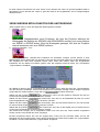
Einleitung
Dieses Programm wurde zur Steuerung von Diskothekenbeleuchtungssystemen entwickelt. Die
Hauptvorteile liegen in der hohen Anwenderfreundlichkeit und die schnelle Steuerung verschiedenster
Lichteffekte über die aktualisierbare Scannerbibliothek. Das Programm bietet eine bedienerfreundliche
Oberfläche mit spezifischen Icons für jede Funktion (Farbe, Gobo) oder Pan/Tilt-Feldern für die
Spiegelbewegungen (die sich jedoch auch mit konventionellen Fadern steuern lassen). Die Daten werden
über das über den Druckeranschluß verbundene DMX-Interface an die Projektoren ausgegeben.
Hauptfeatures:
1. Mit dem Programm lassen sich alle DMX-gesteuerten Projektoren ansteuern.
2. Es lassen sich beliebig viele Projektoren in der DMX-512 Kette ansteuern.
3. Eine SHOW besteht aus bis zu 256 SEQUENZEN, SEQUENZ - 16384 SCENES. Es lassen sich beliebig
viele SHOWS erstellen.
4. Jeder Projektortyp kann seine eigene Oberfläche (control panel) bekommen, auch mit Farb- und GoboIcons.
5. Traditionelle Programmierungsoptionen - Pan/Tilt-Swap und -Reverse, multi-Sequenz-Modus, etc.
6. Die Musiksteuerung kann sowohl intern wie extern erfolgen. Möglichkeit der MIDI-Steuerung,
Sequenzer-Software, etc.
7. Manuelle Ansteuerung jedes Projektors jederzeit möglich.
8. Extrem schnelles Hinzufügen eines neuen Projektors zur vorher erstellten SHOW über die Kopier- und
Editierfunktion.
9. Erweiterbare Scannerbibliothek über integriertes Design-Modul (Panel Designer)
10. Für Windows 95/98 mit einer Bildschirmauflösung von 800x600 Pixel oder höher.
1
INHALT:
LIEFERUMFANG .............................................................................................................................................. 3
ANSCHLUSS DER HARDWARE ..................................................................................................................... 3
SPANNUNGSVERSORGUNG.......................................................................................................................... 3
ANSCHLUSS DER PROJEKTOREN ............................................................................................................... 3
MUSIKSTEUERUNG......................................................................................................................................... 3
INSTALLATION DER SOFTWARE .................................................................................................................. 3
PROGRAMMSTART ......................................................................................................................................... 3
SHOW-PROGRAMMIERUNG .......................................................................................................................... 4
ANFANG ........................................................................................................................................................... 4
SHOW-STRUKTUR........................................................................................................................................... 5
ERSTELLEN EINER SEQUENZ....................................................................................................................... 5
WIEDERGABE VON SEQUENZEN UND SHOW ............................................................................................ 6
KOPIEREN VON SZENEN ............................................................................................................................... 7
MONITOR, FADER, PLAN ............................................................................................................................... 7
LISTE DER SEQUENZEN ................................................................................................................................ 7
AUSWAHL EINES PROJEKTORS UND EINGABE VON TEXT ..................................................................... 8
VERSCHIEDENE MÖGLICHKEITEN DER ANSTEUERUNG ......................................................................... 9
MENÜ WEITERER FUNKTIONEN ................................................................................................................. 11
ZUSATZLICHES TOOLBAR .......................................................................................................................... 13
MULTI-SEQUENCE PLAYER......................................................................................................................... 14
PLAY LIST ...................................................................................................................................................... 15
MEDIA PLAYER.............................................................................................................................................. 16
DAS TOOLBAR ZUR SHOW WIEDERGABE................................................................................................ 17
SYNCHRONISATION, MIDI UND HARDWARE ............................................................................................ 18
DAS DATEI-TOOLBAR .................................................................................................................................. 20
DIE BLACK OUT TASTE................................................................................................................................ 21
DIE «FAVOURITE» TASTE ............................................................................................................................ 21
VALUES/TEMPO EDITOR.............................................................................................................................. 21
TRACK EDITOR.............................................................................................................................................. 24
POSITIONSSPEICHER................................................................................................................................... 24
ZUWEISUNG VON FUNKTIONSTASTEN ..................................................................................................... 26
DMX SIGNALPARAMETER ........................................................................................................................... 27
SERVICE PANEL DESIGNER........................................................................................................................ 28
2
LIEFERUMFANG
Das Softwarepaket Wizard-512 umfasst
-
1 Druckeranschlussleitung
1 DMX-Interface
1 CD-Rom
1 Bedienungsanleitung
1 Netzteil
ANSCHLUSS DER HARDWARE
Schließen Sie die Druckeranschlussleitung an die parallele Schnittstelle Ihres PCs und an das Interface an.
SPANNUNGSVERSORGUNG
Schließen Sie das Interface über das beiliegende Netzteil an das Spannungsnetz an.
ANSCHLUSS DER PROJEKTOREN
Schließen Sie den ersten Projektor über die DMX-Eingangsbuchse an das Interface an. Verbinden sie
weitere Projektoren über die DMX-Ausgangsbuchse miteinander.
MUSIKSTEUERUNG
Die Musiksteuerung geht entweder über das eingebaute Mikrofon im Interface oder über Ihr externes
Audiomischpult. Sobald Sie die 6,3 mm Mono-Klinkenbuchse mit dem Mischpult verbinden, wird das interne
Mikrofon deaktiviert.
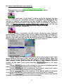
INSTALLATION DER SOFTWARE
Speichern Sie die auf der CD-Rom enthaltenen Dateien auf Ihrer Festplatte in einem neuen Ordner ab. Die
Installationsdateien sind mit dem Komprimierungsprogramm Winzip gepackt. Falls Sie dieses Programm
noch nicht auf Ihrem PC installiert haben, können Sie es im Internet unter www.winzip.com downloaden.
Installieren Sie das Programm. Entpacken Sie die *.zip Datei in Ihr aktuelles Verzeichnis.
Starten Sie das Programm Setup.
Folgen Sie den Bildschirmanweisungen.
Sobald die Installation abgeschlossen ist, sollten Sie Ihren Rechner neu starten.
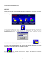
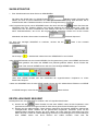
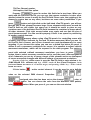
PROGRAMMSTART
Starten Sie das Programm über die Startleiste oder vom Desktop aus. Wenn das Interface nicht
angeschlossen worden ist, erscheint eine Fehlermeldung, die darauf hinweist, daß Sie das Programm dann
nur im Demo-Modus betreiben können. Dabei sind jedoch auch sämtliche Funktionen verfügbar und die
vorgenommenen Einstellungen können auch abgespeichert werden.
3
SHOW-PROGRAMMIERUNG
ANFANG
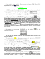
Achtung! Wenn nach dem Programmstart die Fehlermeldung «DMX device is inaccessible» ("Kein DMXInterface") erscheint, lesen Sie bitte unter "Treiberinstallation des DMX-Interface".
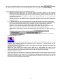
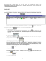
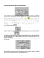
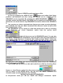
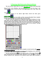
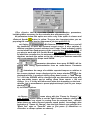
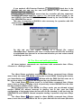
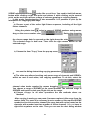
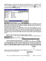
Nach dem Programmstart erscheint folgender Ablauf:
Um eine SHOW zu programmieren, drücken Sie
, und Sie werden aufgefordert, den DMX-Patch
zu konfigurieren (bitte beachten Sie die Hinweise unter "DMX-Kanäle"). Hier können Sie die zu
programmierenden Projektoren hinzufügen oder entfernen und Sie werden aufgefordert, die erste
SEQUENZ zu betiteln:
.
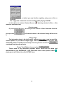
Wenn Sie eine vorher bereits programmierte SHOW aufrufen möchten, drücken Sie
Standardablauf zum Aufrufen einer Datei erscheint.
und der
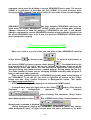
So können Sie die SHOW programmieren oder verändern. Wenn Sie jedoch ab Einrichten von Control
Panels starten möchten folgen Sie den unten beschriebenen Schritten.
Mit der
Taste öffnen Sie den «Control Panel Designer». Bitte beachten Sie die Hinweise
weiter unten in dieser Anleitung.
4
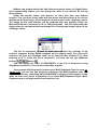
SHOW-STRUKTUR
1. Eine SHOW besteht aus einer Reihe von SEQUENZEN.
geändert werden. Zwischen dem
Der Name der SHOW kann im SHOW-Fenster
Namen der Show und dem Dateinamen der Show gibt es keine Verknüpfung. Bitte benutzen Sie im
SHOW-Fenster keine Tastenkombination, die sie für die Programmierung verwenden.
2.Die Programmierung einer neuen SEQUENZ starten Sie durch Drücken der
Taste. Der Name der
SEQUENZ wird beim Erstellen definiert oder jederzeit während die SHOW editiert wird, indem Sie
«Sequences List» aus dem Auswahlmenü unter Settings oder über F7 auswählen. Bitte benutzen Sie
keine Tastenkombination, die sie für die Programmierung verwenden. Klicken Sie mit der rechten
Maustaste und wählen Sie aus dem Kontextmenü
"Rename Sequence"
Um eine nicht benötigte SEQUENZ zu entfernen, drücken Sie die
SEQUENCES:
Die Anzeige <<
Taste in der Auswahl
>> bedeutet die Indexnummer der SEQUENCE in einer SHOW.
3.Die SEQUENZ besteht aus einer Anzahl SZENEN. Die Programmierung einer neuen SZENE wird über die
Taste gestartet. Der Name der SZENE kann jederzeit geändert werden. Durch Drücken der
Taste in der Auswahl SCENE können Sie eine nicht benötigte SZENE löschen.
Unter einer SZENE versteht man das Gesamtbild der angeschlossenen Projektoren zu einem
bestimmten Zeitpunkt.
4.Wenn die SEQUENZ mehr als eine SZENE enthält, können Sie sich während dem Editieren von SZENE
zu SZENE bewegen, indem Sie die
Tasten drücken.
ERSTELLEN EINER SEQUENZ
Die bequemste Art, eine SEQUENZ zu erstellen, wird im Folgenden beschrieben:
Taste. Erstellen Sie die erste SZENE, indem Sie alle Projektoren in die
a) Drücken Sie die
gewünschten Positionen bringen und die für diese Szene gewünschten Einstellungen vornehmen.
b) Drücken Sie die «NEW SCENE» Taste. Dadurch übernimmt die folgende SZENE die Attribute der
vorhergehenden Szene. Wählen Sie die gewünschten Projektoren, Positionen (wenn Sie die
Strahlenposition verändern können Sie durch Halten der CTRL-Taste die horizontale und durch
Halten der SHIFT-Taste die vertikale Bewegung einfrieren) und Einstellungen aus. Die Einstellungen
einer SZENE lassen sich durch Drücken der «NEW SCENE» Taste oder der
5
Tasten abspeichern. Die Befehle Next und Previous lassen sich auch aus
dem Szenen-Menü oder über die Tastenkombinationen Ctrl+A und Ctrl+Q aufrufen.
c) Eine SEQUENZ wird erstellt und erweitert, indem Sie die «NEW SCENE» Taste drücken und die
Projektorenauswahl
und
die
gewünschten
Einstellungen
abspeichern.
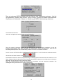
Wenn dies notwendig ist, können Sie eine ganze Anzahl indentischer Szenen neu erstellen, indem
Sie auf die
Taste drücken und dann die benötigte Anzahl der SZENEN in diesem Fenster
.
eingeben
1. Jede SEQUENZ läßt sich auf die Festplatte und/oder Diskette abspeichern und aufrufen, indem Sie im
Edit-Feld mit dem Namen der entsprechenden SEQUENZ die rechte Maustaste drücken.
2. Jede SZENE läßt sich auf die Festplatte und/oder Diskette abspeichern und aufrufen, indem Sie im EditFeld mit dem Namen der entsprechenden SZENE die rechte Maustaste drücken.
WIEDERGABE VON SEQUENZEN UND SHOW
Wenn Sie Ihre aktuelle Show testen möchten, können Sie die aktuelle Sequenz durch Drücken der
-Taste im Menü
abspielen. Zum Stoppen der Wiedergabe drücken Sie die
. Die Hot Keay für beide Befehle ist F12 oder benutzerdefiniert, dabei sollte jedoch der Befehl Play
und Stop die gleiche Kombination erhalten. Wie Sie während der Wiedergabe feststellen können, ändert sich
das Control Panel des gewählten Gerätes (Strahlenbewegung, markierte Tasten, rotierende Regler etc.).
Dies geschieht genauso wenn Sie die Szenen manuell ändern während sich das Program im Editiermodus
befindet. Außerdem ist es möglich, eine Sequenz physisch abzuspielen während eine beliebige Sequenz
online geändert wird. Dazu wählen Sie aus dem Kontextmenü der Play-Taste die Option „Play Current
Sequence in Background“ aus. Während der Hintergrundwiedergabe (background playing) der SEQUENZ
(angewählte Sequenz beim Start der Hintergrundwiedergabe), haben alle Geräte die gleichen Funktionen
wie bei der gewöhnlichen Wiedergabe.
Links von der Play-Taste befindet sich die „Cycle Sequence“ Taste
. Wird diese Taste gedrückt,
beginnt die Wiedergabe nach der letzten Szene wieder am Anfang, bis die Taste erneut gedrückt wird.
Die „External Synch“
Taste dient zum Schalten in den Synchro-Modus. Bei gelber Hinterlegung
erfolgt die Synchronisation über die externe Musikquelle. Die Parameter der externen Synchronisation
können wie unter Synchronization, MIDI and Hardware beschrieben verändert werden.
Bei blauer Hinterlegung
erfolgt die Synchronisation über den tempo track. Bei grüner Hinterlegung
wird die Szenenschaltung über einen internen Beat-Generator geschaltet, dessen Frequenz sich im
Frequenz-Fenster
einstellen läßt. Die Frequenz in BPM läßt sich auch manuell einstellen, indem Sie
auf die „Manual Tempo Correction“ Taste
tippen.
Bitte beachten Sie auch die Hinweise unter „Multi-Sequence Player“.
6
KOPIEREN VON SZENEN
Die
Taste kopiert eine SZENE in die Zwischenablage und durch Klicken auf das SCENES Menü
und
. Die kopierte SZENE kann überall innerhalb einer SEQUENZ
erscheinen die Tasten
eingefügt werden, indem Sie die «Insert» Taste drücken oder eine Szene überschreiben, indem Sie die
«Replace» Taste drücken.
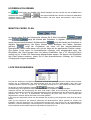
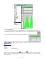
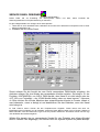
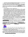
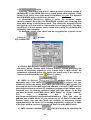
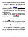
MONITOR, FADER, PLAN
Im oberen linken Eck des Haupmenüs können Sie 3 Modi auswählen:
,
und
.
zeigt die Kanäle des Projektors in digitaler Dezimaldarstellung
sowie die benutzerdefinierten Feldüberschriften.
zeigt die Kanäle des Projektors in
digitaler Faderdarstellung (die Werte können durch Bewegen des Faders verändert
werden).
zeigt die Projektoren als Icons mit den benutzerdefinierten
Überschriften; diese Icons lassen sich mit der Maus an die gewünschte Position ziehen.
(Die Option «Lock icons» im Auswahlfenster «Setting» muß ausgeschaltet sein). Die
Oberfläche des Plan-Fensters kann mit jedem Grafikeditor (wie z. B. Microsoft Paint)
erstellt und im 16 oder 256 Farbmodus abgespeichert werden. Sie können die Oberfläche
des Plan-Fensters ersetzen, indem Sie in dem Auswahlfenster «Setting» die Funktion
«Change plan image» auswählen.
LISTE DER SEQUENZEN
Die Liste der Sequenzen ermöglicht eine schnelle Auswahl der benötigten Sequenz während eines SHOWAblaufs und im Editiermodus. Die Sequenzenliste läßt sich über das Settings-Menü oder über eine
Tastenkombination aufrufen (Vorgabe F7). Ein erneutes Drücken der F7-Taste schließt das Menü wieder.
Sie können auch die zusätzliche Auswahl
verwenden, Taste
.
Die Reihenfolge der aufgeführten Sequenzen läßt sich durch Drag&Drop beliebig verändern.
Außerdem können Sie die Belegung der Short Cuts ändern. Dazu ist es notwendig, die entsprechende
Sequenz auszuwählen und über die rechte Maustaste aus dem Auswahlfenster den gewünschten Short Cut
(zwischen Alt + 1 bis Alt + 0) auszuwählen. Die Belegung der Short Cuts wird in einer SHOW-Datei
abgespeichert und beim Öffnen der Datei auch wieder geladen.
In der Liste der Sequenzen können Sie des weiteren die Anordnung der Sequenzen durch Drag and Drop
ändern.
Wenn Sie die Sequence List bedienen währende der Multi-sequence Player geöffnet ist, werden Sie
feststellen, dass die Sequence List zur Multi-sequence Map wird. Dort können Sie die Kontrollkästchen
aktivieren, um damit festzulegen, welche Sequenz in welchem Player abläuft. Wenn Sie den Multi-sequence
Player schließen wird die Multi-Sequence Map wieder zur Sequence List.
7
AUSWAHL EINES PROJEKTORS UND EINGABE VON TEXT
Wählen Sie im Fenster «Monitor» den gewünschten Projektor durch Klicken mit der linken Maustaste aus:
,
oder aus der Projekorenliste unter «Sliders»,
oder über das Icon im Fenster «Plan»:
.
Dann wird die Farbe dunkelgrün
, Überschrift des gewählten Projektors weiß und
auf der rechten Seite erscheint die passende Projektorvorlage.
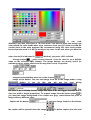
Die Projektorattribute (Pan/Tilt bei Scannern, Farbe, Gobo, etc.) lassen sich über die Fader im Fenster
«Sliders», durch manuelle Eingabe der Dezimalwerte in der Edit-Auswahl im Fenster «Monitor» oder über
die Projektor-Icons. Eine Projektorvorlag könnte ungefähr so aussehen:
Die meisten in Diskotheken eingesetzten Projektoren belegen i. A. 4 oder mehr DMXKanäle. Die Projektorvorlagen lassen sich mit dem Vorlagendesigner erstellen.
Wie man Projektorvorlagen erstellt läßt sich am besten anhand der im Programm enthaltenen Vorlagen oder
über die Hilfedatei des Vorlagendesigners lernen.
8
Im linken oberen Eck befinden sich zwei Tasten. Durch Drücken der Taste “B” geht das gewählte Gerät in
den Blackout. Durch Drücken der Taste “D” geht das Gerät in die Vorgabewerte, die im Vorlagendesigner
definiert wurden.
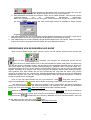
VERSCHIEDENE MÖGLICHKEITEN DER ANSTEUERUNG
Jeder Projektor kann in einem der folgenden Modi angesteuert werden:
1. NORMAL - «grün»
Dies ist der Standardmodus eines Projektors, bei dem der Projektor während der
Wiedergabe die Befehle der SZENEN und SEQUENZEN ausführt und seine Attribute
von SZENE zu SZENE ändert. Wird die Wiedergabe gestoppt, läßt sich der Projektor
manuell ansteuern oder eine SZENE editieren.
2. LOGICAL MASTER - «rot»
Der „Logical Master“ verbindet alle Projektoren mit denselben Vorlagen (control panels) in einer
Mastergruppe. Dieser Modus läßt sich aufrufen, indem Sie die Ctrl-Taste halten und mit der Maustaste auf
das Projektor-Icon oder seine Kopfzeile klicken. Beim ersten Mal werden dabei alle ausgewählten
Projektoren auf den Modus Full Master gesetzt. Über das folgende Submenü lassen sich verschiedene
„Logical Masters“ auswählen:
der "Master for Devices Group" im Kontextmenü des Projektor-Icons. Wenn Sie einen der „Logical Masters“
aus dem Submenü auswählen, kommen alle Projektoren mit derselben Vorlage in diese Gruppe. Die ganze
im selben Untermenü.
Gruppe läßt sich wieder auflösen, indem Sie auf
des Untermenüs, wenn Sie alle möglichen Features der über ein
Wählen Sie die Funktion
Control Panel ausgewählten Gruppe ansteuern möchten.
des Untermenüs, wenn Sie nur die Farbkanäle der über ein Control
Wählen Sie die Funktion
Panel ausgewählten Features der Gruppe ansteuern möchten.
des Untermenüs, wenn Sie alle Kanäle außer Pan und Tilt der über
Wählen Sie die Funktion
ein Control Panel ausgewählten Gruppe ansteuern möchten.
Wählen Sie die Funktion
des Untermenüs, wenn Sie nur die Kanäle Pan und Tilt der über ein
Control Panel ausgewählten Gruppe ansteuern möchten.
Alle Kanäle einer Gruppe, die so ausgewählt werden und nicht über den "Roten Master" angesteuert
werden, werden in der SHOW als "Grün" angezeigt.
Einzelne Projektoren lassen sich aus der Gruppe lösen, indem Sie die Ctrl-Taste halten und mit der
Maustaste auf den Projektor klicken. Wenn Sie bei gedrückter Ctrl-Taste einen Projektor mit „Logical Master“
auswählen, wird der zuletzt definierte „Logical Master“ ausgeführt.
9
Alle "roten" Projektoren lassen sich aus der Gruppe lösen, indem Sie in dem Menü
“Master
Off” drücken, das nur erscheint, wenn überhaupt Projektoren im "roten Master" angesteuert werden.
Der Logical Master Modus verfügt über 2 einzigartige Features
a) Während der Wiedergabe werden die in diesem Modus ausgewählen Geräte von den folgenden
SHOW-Steuerungen abgekoppelt und führen die Befehle aus der Projektorvorlage aus. Dadurch
können ganze Projektorgruppen während einer SHOW manuell angesteuert werden. Es lassen sich
verschiedene Arten "roter" Projektoren anlegen; diese lassen sich aber nur von einem Panel
derselben Art ansteuern.
Außerdem lassen sich spezielle Attribute eines einzelnen Projektors über das Fenster «Slider» oder
«Monitor» ansteuern. Die restlichen "roten" Projektoren der gleichen Art ändern ihre Parameter in
diesem Fall nicht.
b) Im Editiermodus kann die Projektorvorlage einer Gruppe die Attribute der aktuellen Szene ändern.
Damit läßt sich dieser Modus zum Editieren einer Gruppe einer Show verwenden. Dieser Modus läßt
sich über die den Menüpunkt "Select Group for Master" aus dem Auswahlfenster "Additional
operation menu" oder über die Auswahl eines Projektors bei gedrückter "Ctrl" Taste.
Obwohl der "rote" Master keine eigene Channel Map wie der "gelbe" Master hat, können Sie die
"gelbe" Channel Map verwenden, um einige Kanäle aus der "roten" Mastersteuerung
herausnehmen. Doppelclicken Sie dazu auf die entsprechenden roten Zellen der "gelben" Channel
Map.
Außerdem ist es wichtig zu wissen, dass die Befehle
,
,
und
des Auswahlfensters "Additional operation menu" für die "roten"
Projektoren gesperrt sind.
3. MANUAL - «blau»
Dieser Modus dient nur zur manuellen Ansteurung. Die Attribute eines Projektors lassen sich auf alle
möglichen Arten verändern während der Wiedergabe und im Stop-Modus. In diesem Modus folgt der
Projektor nur manuellen Befehlen.
Der MANUAL Modus läßt sich durch Drücken und Halten der Shift-Taste während der Auswahl des
Projektors ein- bzw. ausschalten.
Obwohl der "blaue" Master keine eigene Channel Map wie der "gelbe" Master hat, können Sie die
"gelbe" Channel Map verwenden, um einige Kanäle aus der "blauen" Mastersteuerung herausnehmen.
Doppelclicken Sie dazu auf die entsprechenden blauen Zellen der "gelben" Channel Map.
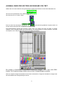
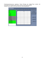
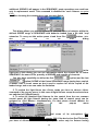
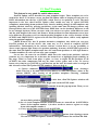
4. PHYSICAL MASTER - «gelb»
Dieser Modus dient nur zur manuellen Ansteuerung bestimmter Fader. In diesem Modus können Sie die
Steuerung einiger DMX-Kanäle einem Fader des Physical MASTER zuweisen. Kanäle, die dem Physical
MASTER zugewiesen wurden, sind von der Show-Steuerung abgekoppelt. Es können bis zu 8 Physical
MASTERS verwendet werden. Die Physical MASTER Steuerung hat einen hohen Status und läßt sich
nur über das Physical MASTER Fenster ändern.
10
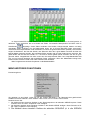
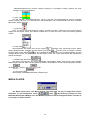
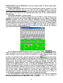
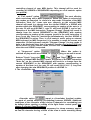
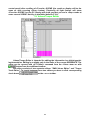
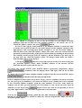
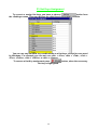
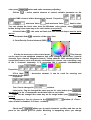
Im Physical MASTER Fenster müssen Sie die „View Table“ Taste drücken, um die Konfiguration zu
definieren. Darin erscheinen alle 512 Kanäle als Zellen. Die aktuelle Zellenposition der Maus wird im
angezeigt. Graue Zellen bedeuten freie Kanäle, belegte Kanäle werden mit farbig
Kanalfenster
unterlegten Zellen angezeigt. Um die DMX-Kanäle einem der 8 Physical MASTER Fader zuzuordnen,
müssen Sie die entsprechenden Fader auswählen und dann die gewünschten Zellen (Kanäle). Grüne Zellen
zeigen die Kanäle an, die über die SHOW, rote Zellen die über den Logical Master und blau die über den
Manual Master gesteuert werden. Die gewählten Zellen werden gelb und die Fadernummer erscheint. Der
gelbe Modus hat die höchste Priorität, d. h. Sie können keinen gelben Kanal ansteuern bis Sie ihn grün
gemacht haben. Doppelklicken Sie dazu erneut auf die entsprechende Zelle. Der Haupt-Masterfader läßt
sich zum synchronen Bewegen aller angeklickten Fader verwenden. Wenn der Masterfader bewegt wird,
lassen sich die einzelnen Fader nicht mehr anklicken oder abwählen.
Beim Programmstart sind alle Projektoren im NORMALMODUS.
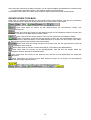
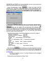
MENÜ WEITERER FUNKTIONEN
Erscheinungsform:
Sie gelangen zu dem Menü, indem Sie mit der rechten Maustaste in die Überschrift des gewünschten
Gerätes im Fenster «Monitor» oder «Sliders» oder auf ein Icon im Fenster «Plan» klicken.
Dadurch können Sie:
1. Die Attribute eines einzelnen Gerätes in den Zwischenspeicher der aktuellen SZENE kopieren. Diese
Funktion ist für die "roten" Projektoren nicht verfügbar.
2. Die kopierten Attribute eines einzelnen Gerätes in die aktuelle SZENE einfügen. Diese Funktion ist für
die "roten" Projektoren nicht verfügbar.
3. Die Attribute eines einzelnen Gerätes der aktuellen SEQUENZ (d. h. alle SZENEN
11
einer bestimmten Auswahl an SZENEN und bis zu einer SZENE der aktuellen
SEQUENZ) in den Zwischenspeicher kopieren (Diese Funktion ist für die "roten"
Projektoren nicht verfügbar):
Außerdem lassen sich die Attribute der gewählten Geräte von der Sequenz in einer Datei abspeichern
(drücken Sie dazu die
Außerdem
haben
(
Sie
-Taste).
die
Möglichkeit
die
erste
(
Option)
und
die
letzte
Option) SZENE der Serie zu bestimmen, die innerhalb der SEQUENCE kopiert wird.
4. Eine Reihe Szenen eines einzelnen Gerätes in die aktuelle Sequenz einfügen.
Diese Funktion ist für die "roten" Projektoren nicht verfügbar. Außerdem haben Sie die Möglichkeit die erste
(
Option) und die letzte (
innerhalb der SEQUENCE eingefügt wird.
Über die Funktion
Option) SZENE der Serie zu bestimmen, die
können Sie die Szenen aus einer bereits vorhandenen Sequenz-Datei laden.
5.Das Gerät in den «Solo» Modus schalten; in diesem Fall sind alle Geräte außer dem gewählten Gerät
ausgeschaltet.
6.Alle identischen Geräte über die Gerätevorlage ansteuern.
7.Den Track Editor anzeigen, wenn das Gerät über eine Pan/Tilt-Steuerung verfügt.
12
8.Die Werte des Values/Tempo Editors anzeigen, um die Geschwindigkeit der SEQUENZ zu verändern oder
um einige Kopier-/Einfügevorgänge in der digitalen Grafikansicht auszuführen.
9.Das Gerät in den «Black Out» fahren oder aus dem Programmablauf der SHOW herausnehmen.
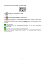
ZUSATZLICHES TOOLBAR
Ganz oben am Hauptfenster befindet sich das Lineal mit den Funktionstasten, über die Sie verschiedene
Fenster öffnen können. Alle diese Tasten beinhalten die Funktionen des "View" Menüs.
Diese Taste öffnet ein Fenster mit den Bezeichnungen der verschiedenen Geräte, ihrer
Kanaleinstellungen etc.
Diese Taste öffnet ein Fenster mit den Bezeichnungen der verschiedenen Geräte und einem Feld
mit Fadern, über die sich die DMX-Werte einstellen lassen.
Diese Taste öffnet ein Fenster mit den Icons und User names der verschiedenen Geräte.
Diese Taste öffnet ein Fenster das den ganzen unteren Teil des Hauptfensters ersetzt mit 2
Hauptmenü-Editoren, DMX-Wert-Editor um die DMX-Kanalwerte zu ändern und dem Tempo-Track Editor,
um die Intervalle zwischen den einzelnen Szene einzustellen.
Diese Taste öffnet ein Fenster mit Beam Track Editor, über den sich geometrische Formen als
Bewegungsabläufe steuern lassen.
Diese Taste öffnet ein Fenster mit dem Media Player zur Einstellung der Media-Dateien.
Diese Taste öffnet ein Fenster mit der Wiedergabeliste, über die sich die exakten Zeiten der
verschiedenen Aktionen einer Show einstellen lassen.
Diese Taste öffnet ein Fenster mit der Sequenz-Liste, über die sich die Reihenfolge der Sequenzen
einstellen lässt.
Diese Taste öffnet ein Fenster mit dem Multi Sequence Player mit 12 Playern die verschiedenen
Sequenzen gleichzeitig abspielen können.
Diese Taste ist nur sichtbar, wenn einige Master-Modi aktiv sind.
13
MULTI-SEQUENCE PLAYER
Wenn Sie spezielle Sequenzen mit mehreren Features Ihrer Ausstattung mischen möchten, benötigen
Sie den Multi-Sequence Player. Um den Multi-Sequence Player aufzurufen, drücken Sie die
Taste der
oder drücken Sie die Tastenkombination (Vorlage F8) oder wählen Sie
zusätzlichen Leiste
Multi-Sequence Player im Menü Settings. Sobald Sie den Multi-Sequence Player starten werden alle
Editierfunktionen gesperrt. Bevor Sie anfangen, mit dem Multi-Sequence Player zu arbeiten, möchten wir
Ihnen einige Ratschläge geben:
1. Um den Multi-Sequence Player auszuprobieren, empfehlen wir, vorerst nur sehr simple
Sequenzen zu verwenden, z. B. Farbwechsel o.ä. Bitte beachten Sie, daß alle nicht verwendeten
Kanäle auf 0 gesetzt werden. Als nächstes können Sie andere Sequenzen programmieren mit
allen Kanälen Ihrer Projektoren außer den Kanälen, die vorher auf 0 gesetzt wurden.
2. Steuerung von Sequenzen im Multi-Sequence Player.
Der Multi-Sequence Player enthält immer alle Sequenzen Ihrer aktuellen Show. Wenn Sie den
Multi-Sequence Player zum ersten Mal öffnen nach Erstellen einer neuen Show können Sie alle
programmierten Sequenzen sehen in einer der 4 Listen sehen. Bitte beachten Sie, daß nur aktive
Sequenzen in einer Liste aufgeführt werden. Um eine Sequenz zu aktivieren müssen Sie auf Ihren
Namen klicken und das Zahlenfeld wird dunkelblau. Wenn Sie die
Taste drücken oder die
Tastenkombination (Vorlage F12), werden Sie fast keinen Unterschied zwischen normaler
Wiedergabe und Wiedergabe mit einer Liste an Sequenzen feststellen (bitte beachten Sie die
Hinweise unter Sequence List). Um den Unterschied festzustellen, versuchen Sie Sequenzen (im
Stop-Modus) von der ersten Liste in eine andere zu ziehen (dabei ist es jedoch nicht möglich, die
Anordnung der Sequenzen innerhalb der Liste zu verändern). Schalten Sie dann
wo
ist weiß). Nun können Sie die Wiedergabe im
notwendig um Listen zu aktivieren (Taste
Multi-Sequenz Mix starten.
3. Was können Sie während der Wiedergabe verändern:
Auswahl aktiver Sequenzen.
schalten. Dabei bedeutet off „BlackOut“.
Listen
Die Option „Cycle Sequence“ „ “, wobei bei ungedrückter Schaltfläche die Sequenz einmal
wiedergegeben wird und an der letzten Szene stoppt.
, „Tempo Track“
und „External“
(vom Audio
Den „Synchro“ Modus. „Main“
Beat-detector). Im „Main“ synchro Modus können Sie die Taktschläge in bpm manuell eingeben.
Jede der bestehenden Masterfunktionen (bitte beachten Sie die Hinweise unter Possible
master modes).
Der Multi-Sequence Player läßt sich in der Toolbar integrieren, indem Sie auf die Taste „ “
klicken. Um den Multi-Sequence Player wieder aus der Toolbar zu nehmen, drücken Sie die „ “
Taste.
Die „BlackOut“ und „Favorite“ Tasten.
4. Was können Sie im Stop-Modus ändern:
Das gleiche wie unter Wiedergabe.
Drag&Drop zwischen den Listen.
Bitte beachten Sie: Werden aktive Sequenzen im Stop-Modus verändert, verändert sich die
Projektion erst mit Starten der
Taste.
Um den Multi-Sequence Player wieder zu verlassen, drücken Sie die Tastenkombination (Vorlage
„F8“).
Das Hauptprinzip der Sequenzmischung ermöglicht es, den maximalen DMX-Wert von 4 (oder
weniger) gleichen Mischkanäle der aktiven Sequenzen.
14
Bitte beachten Sie: In diesem Modus wird „Full MIDI control“ nicht unterstützt, Sie könne nur die
Sequenznummer ändern wenn Sie MIDI Note On verwenden (bitte beachten Sie die Hinweise unter
Synchronization, MIDI und Hardware).
PLAY LIST
Sie benötigen die Play List, um größere, komplizierte Shows mit dem internen Timer synchronisieren
zu können. Um die Play List zu öffnen, wählen Sie die View Play List-Option im Settings-Menü oder drücken
Sie die
Taste der zusätzlichen Leiste
oder drücken Sie den Hot Key F6. Danach
erscheint ein aktives Fenster, das, wenn es das erste Mal geöffnet wird, ungefähr so aussieht:
Danach müssen Sie die erste Zeile aktivieren durch Drücken der Enter-Taste aktivieren. Drücken Sie
erneut Enter, um die nächste Zeile zu aktivieren, wenn das Nummernfeld aktiv ist
.
1. Start Time Feld.
Es ist wichtig zu wissen dass die Play Liste sofort startet, wenn die
Taste gedrückt wird. Die
interne Zeit wird gemessen ab dem Wert, der im Start Time Feld der ersten aktiven Zeile erscheint.
Die Zeilen werden automatisch sortiert, so dass eine spätere Zeit eine höhere Ordnungszahl
bekommt.
2. Sequence Feld.
Wählen Sie die benötigte Sequenz aus dem Auswahlmenü aus. Wenn Sie keine Sequenz
benötigen, wählen Sie das Feld
3.Multi Sequence player number Feld.
Wenn die Nummern 1 bis 12 aus der Auswahlliste gewählt werden, öffnet sich der Multi-Sequence
Player und startet mit dem entsprechend angewählten Player. Dieser Player enthält die im Sequence
Feld ausgewählte Sequenz. Wenn keine Nummer ausgewählt wird, wird der Multi-Sequence Player
nicht aktiviert, bzw. sogar geschlossen, wenn er vorher geöffnet war.
Wenn Sie mehrere Player (des Multi-Sequence Player) gleichzeitig starten möchten, müssen Sie
mehrere Zeilen gleichzeitig erstellen..
4. Tempo Feld.
Hat die gleichen Standard-Funktionen. Das Haupt-Tempo Feld
und Tempo
aktiviert sind.
5. Smooth Feld.
15
ist inaktiv wenn die Play List
Aktiviert/Desaktiviert die “Smooth” Funktion (analog zur “Crossfade” Funktion), ähnlich wie unter
“Settings”-“Synch and Hardware”.
6. Synch Feld.
Hat die gleichen Standard-Funktionen. Kann im Normal und Multi-Sequence Player verwendet
werden. Dieses Feld wird z. B. benötigt wenn Sie Midi-Dateien mit Lichtsteuerinhalt über einen virtuellen
Midi-Treiber starten möchten.
7. Cycle Feld.
Kann im Normal und Multi-Sequence Player verwendet werden. Sequenzen ohne Cycle-Funktion
stoppen bei der letzten Szene. Die nächste Schleife kann nur über die Timer- und Goto-Funktion gestartet
werden.
8. Action Feld.
Normalerweise wird diese Feld mit der Option
verwendet, aber manchmal können andere
, um den Timer zu stoppen. Erstellen
Option benötigt werden. Erstellen Sie eine Zeile mit der Option
Sie eine Zeile mit der Option
um zum Wiederholungsteil der Play List zu gelangen(geben Sie eine
niedrige Zeilennummer ein). Wählen Sie die Stop-Option, wenn Sie nur die erste Szene der dargestellten
Sequenz benötigen.
9. Media Player MCI Feld.
Mit diesem Feld können Sie einige Medienfiles wiedergeben. Diese Files können über spezielle
Markierungen zwischen Start und Stop gesteuert werden. Diese Marken können als Zeit dargestellt werden,
die bei
beginnt und bei
endet.
10. Comments Feld.
Beschreiben Sie die Aktion der Zeile in diesem Feld.
MEDIA PLAYER
Der Media Player kann vom Menü Settings oder über den Hot key F5 aufgerufen werden.
. Die Bedienung erfolgt wie beim
Außerdem von der zusätzlichen Leiste
, Taste
Windows Media Player (Mplayer.exe). Der Media Player kann auch im Hintergrund laufen, nachdem er
in der Play List aktiviert wurde.
16
DAS TOOLBAR ZUR SHOW WIEDERGABE
Die
Taste dient zum Wiedergabestart der SHOW.
Die
Taste stoppt die Wiedergabe.
Die
Taste setzt die aktuelle SEQUENZ in den Zyklusmodus.
Die
Taste ermöglicht Ihnen, die Wiedergabegeschwindigkeit manuell anzutippen, so daß sie sie an
die Musik anpassen können.
Mit den Up/Down-Tasten können Sie die Geschwidigkeit
auswählen.
zwischen 2 und 600 Szenen pro Minute
ist eine 3-Modi-Taste:
Der Hauptmodus hat die Wiedergabegeschwindigkeit, die wie oben beschrieben
eingestellt wurde.
Dieser Modus hat die Wiedergabegeschwindigkeit der SEQUENZ.
Dieser Modus ermöglicht die externe Audio-Synchronisierung durch den eingebauten Beatsensor im
Interface; weitere Parameter zur Synchronisation finden Sie in dem Auswahlfeld «Setting» , Untermenü
«Synch and Hardware».
17
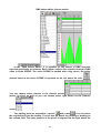
SYNCHRONISATION, MIDI UND HARDWARE
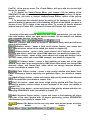
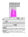
Über die Auswahl «Synch», Option «Bit Detector Enabled», Parameter «Drop down
count» können Sie festlegen, wie viele SZENEN nach verlorener Synchronisation der
Audioquelle gezeigt werden. Dabei ist die "External Synch“
Taste gelb unterlegt. Der
Parameter «Range %» legt fest, in welchem Bereich dem Baßschlag im Vergleich zur
gewählten Abspielgeschwindigkeit gefolgt wird, z. B. «Drop down count» = 1 und «Range
%» = 90%: die SZENEN folgen sofort nacheinander sobald die Mikrofonsignale
empfangen werden auch bei einem sehr unruhigen Takt. «Drop down count» = 100 und
«Range %» = 5 %: Die SZENEN folgen nacheinander unabhänging vom Mikrofon, aber in
Abhängigkeit
der
voreingestellten
Wiedergabegeschwindigkeit
(wie
im
Geschwindigkeitsfenster
).
Über die Auswahl «In Pause»
mit dem Parameter "Pause for Change" können Sie
einstellen, was die Geräte während langer Zeiträume ohne Musiksignal machen sollen. Nach Verstreichen
der Zeit "Pause for Change"
werden die Geräte in den Blackout oder einen FavoritenModus gesetzt. Über die Auswahl "Randomise sequences" können Sie festlegen, daß die folgende Sequenz
einer Show nicht gestartet wird, sondern eine Sequenz zufällig ausgewählt wird, die dann beim Empfangen
des ersten Musiksignals nach der Pause gespielt wird. Dies erlaubt eine automatische Steuerung ohne
Eingreifen des Lightjockeys.
Wenn Sie die Sequenzen und Szenen über eine MIDI-Quelle steuern möchten, wählen Sie die Option "MIDI
Remote Control".
Wenn die beiden Tasten "Synch" und "Play" gewählt werden und der MIDI-Befehl "Note On" auf dem
gewählten MIDI-Kanal empfangen wird, ändert sich die aktuelle Szene auf die Szenennummer, die dem
MIDI-Signal entspricht. Wird der MIDI-Befehl "Program Change"(Patch) empfangen, ändert sich die aktuelle
Sequenz auf die Sequenznmmer (Patch), die dem MIDI-Signal entspricht.
18
Über ein externes MIDI-Pult lassen sich die Szenen und Sequenzen ansteuern. Und mit
den gewählten Treibern "MIDI Router" "Sonic Foundry" können Sie andere weitentwickelte
Sequenzer wie Cakewalk, Cubase zur Gestaltung der MIDI-Lichtsteuerung einsetzen.
Die Auswahl «Movement».
«Smooth» ermöglicht ein sanftes Faden der Pan/Tilt-Kanäle.
Über die Auswahl “Hardware” können Sie die Basisadresse des Druckerports auswählen, an den das
Interface angeschlossen wird. Nach Einstellen der Basisadresse drücken Sie die“TEST” Taste um die
Einstellung abzuspeichern und die Verbindung zwischen Rechner und Interface zu testen.
Danach werden alle DMX-Kanäle am Interface auf "0" zurückgesetzt. Um die Kanalwerte wiederherzustellen
drücken Sie die Taste "Restore" oder
.
Die Auswahl «Autonom» dient zur Programmierung von Blitzprogrammen des Controller der Version 3.5 und
höher. Dadurch läßt sich das Interface ohne Rechner über die Musik ansteuern und Sequenzen und Szenen
abspielen, die vom Rechner aus programmiert wurden.
Nach der Programmierung können Sie den Rechner auschalten und das Interface ausstecken. Die
Wiedergabe erfolgt automatisch wie vorher programmiert.
19
Technische Daten (Version 3.5 des Controllers):
Speicherbare Sequenzen
Anzahl der Szenen je Sequenz
Gesamtkapazität
Anzahl wiederprogrammierbarer Zyklen
Programmierdauer für 2000 Szenen
Sequenzwiedergabe
Audio Pause-Sensor
Pausenüberbrückung
bis zu 100
bis zu 255
2000 Szenen
>10000
~ 7 Minuten (0,2 Sek./Szene)
Zufällig oder aufeinerfolgend
2...120 Sek.
Stop, Blackout, Favourite
Über die Taste "Autonom" können Sie den eigenständigen Betrieb aktivieren. In diesem Modus startet der
erste Baßschlag den Zufallsgenerator.
„AutoBackup“ Bookmark.
Mit dieser Funktion können Sie automatisch eine Auto-Backup Datei „$AutoBak.dmx“ erstellen
lassen. Dabei wird die aktuelle Show in den ausgewählten Zeitabständen in dieser Datei
abgespeichert. Bei einem Systemabsturz oder Stromausfall können Sie dann die letzten Vorgänge
wieder aus dieser Datei laden.
DAS DATEI-TOOLBAR
Mit der
Taste starten Sie eine neue SHOW.
Taste können Sie eine vorher programmierte SHOW von der Festplatte laden.
Mit der
Während der Wiedergabe einer Show können Sie eine weitere Show laden, ohne daß dadurch die
Wiedergabe gestoppt wird, aber in diesem Fall wird die Konfiguration der geladenen Geräte nicht überprüft
sondern nur die Sequenzen und Szenen geladen.
Taste können Sie eine SHOW-Datei abspeichern.
Mit der
Mit der
Taste können Sie unter Save as eine SHOW unter einem neuen Namen abspeichern.
Mit der
Taste können Sie die DMX-Kanäle und die Belegung der Geräte einstellen.
Mit der
Taste können Sie Änderungen in einer SZENE rückgängig machen.
20
DIE BLACK OUT TASTE
Die
Taste schaltet alle Geräte in den Blackout-Modus und stoppt auch die Wiedergabe einer
Show. Bei dieser Funktion wird auch die Wiedergabe der Show gestoppt. Die Funktion kann auch über eine
Tastenkombination aufgerufen werden (Vorlage F11).
DIE «FAVOURITE» TASTE
Die
Taste setzt die Kanäle aller Geräte in den «Favourite» Modus und stoppt die Wiedergabe der
SHOW. Die Werte der «Favourite scene» lasen sich einstellen, indem Sie in einer beliebigen Szene mit der
rechten Maustaste auf die «Favourite» Taste drücken. Die Funktion kann auch über eine Tastenkombination
aufgerufen werden (Vorlage F10).
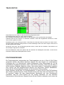
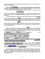
VALUES/TEMPO EDITOR
Dieser Editor dient dazu, die Informationen in einer digital-grafischen Darstellung zu editieren.
Der Editor arbeitet in zwei verschiedenen Modi: " Edit DMX Values " und " Edit Tempo Track ".
Um zwischen diesen beiden Editoren zu wechseln, clicken Sie in das entsprechnde Kontrollkästchen
.
DMX values Editor (wählen Sie die Option
21
).
Editieren von DMX-Werten
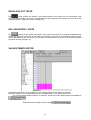
Im "DMX Values Editor" " können Sie die digitalen Werte der DMX-Signale als Spalten editieren. Jede
Spalte zeigt den DMX-Wert einer SZENE des gewählten Kanals. Die aktive SZENE is mit einem großen
Cursor markiert, der Wert des aktiven Kanals in der aktiven SZENE wird links oberhalb des Lineals
angezeigt. Sie können den aktiven Kanal in der Channel Screen
auswählen, wobei grün unterlegt aktiv bedeutet, so wie Sie aktive Projektoren auf der Fixture’s Screen
auswählen können.
und ein Lineal
, die sich aus der Toolbar auswählen
Dabei gibt es zwei Werkzeuge: einen Stift
lassen. Außerdem ist auch Kopieren/Einfügen möglich. Die zu kopierende Information kann wie folgt
ausgewählt werden:
22
Auswahl eines Teil der Gerätesequenz mit allen Kanälen. Wählen Sie die Szenennummern über den Zeiger
aus. Drücken Sie die rechte Maustaste und wählen Sie aus dem Kontextmenü den Befehl "Kopieren". Um
die kopierten Szenen einzufügen, ist es notwendig, die benötigte Szenennummer zu markieren und dann im
Kontextmenü "Einfügen" zu wählen.
Die zweite Methode ist, eine beliebige Anzahl nebeneinanderliegender Tracks zu kopieren. Wählen Sie dazu
die benötigten Attributestracks und Szenen und wählen Sie "Kopieren" im Kontextmenü.
Bei allen anderen Befehlen sind die beiden Methoden identisch. Die Befehle Kopieren/Einfügen sind
während der SHOW-Wiedergabe nicht unterlegt.
(Tastenkombination Ctrl+R) hat hier eine Rückgängig-Funktion.
Die «Refresh» Taste
Clearing
Wenn Sie Funktion Clear Selected aus dem Kontextmenü auswählen werden all Tracks des ausgewählten
Bereichs auf 0 gesetzt.
Editing Tempo Track:
Hier ist als Werkzeug auch ein Stift und ein Lineal verfügbar. Alle Editierbefehle entsprechen denen mit
Editierwerten, aber die Auswahl eines Gerätes hat keinen Effekt. Außerdem läßt sich die Szenenlänge
anzeigen, die Sie mit dem Stift verändern können, so daß die Szenen mit verschiedenen Längen
programmiert werden können. Bei der Wiedergabe hat dann jede Szene eine andere Länge und wenn Sie
während der Wiedergabe
auswählen folgt das Programm diesen Zeitvorgaben. Änderungen im Tempotrack lassen sich nicht rückgängig machen.
23
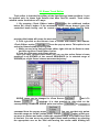
TRACK EDITOR
Dieser Editor kann für Geräte mit Pan/Tilt-Steuerung eingesetzt werden.
Die Strahlenposition läßt sich in allen Szenen anzeigen.
Der Lichtstrahl des gewählten Gerätes läßt sich über die Maus an den gewünschten Ort bewegen.
Außerdem läßt sich eine Gruppe von Positionen auwählen, indem alle ausgewählten Positionen zu einer
neuen Position gefahren werden.
Desweiteren gibt es die "Sewing machine". Damit läßt sich Gerät auf Gerät und Szene auf Szene "säen",
weil alle Geräte zusammen bewegt werden und die Einstellungen Szene auf Szene zeigen außer des mit
der Maus gesteuerten Gerätes.
Sie können auch einen Teil der Bewegung weicher machen, indem Sie die «Linearize» Taste drücken und
den benötigten Algorythmus auswählen.
Das Kontrollkästchen «Real time update» läßt sich während der Wiedergabe umschalten, so daß Sie die
Korrekturen während der Wiedergabe sehen können.
POSITIONSSPEICHER
Die Positionsspeicher entsprechen den Positionspaletten wie sie in Rock & Roll Pulten
verwendet werden. Mit diesen Speichern können Sie eine Anzahl von verschiedenen
Positionen wie z. B. Bühnenmitte, rechter Bühnenrand, linker Bühnenrand etc. für die
angewählten Projektoren speichern und in einer Szene zuordnen. Wenn Sie die Show in
einem anderen Gebäude abspielen wollen, dort jedoch andere Trussinghöhen gegeben
sind, können Sie alle programmierten Szenen und Sequenzen einfach aktualisieren,
indem Sie die Positionspaletten einfach auf den korrekten Wert einstellen.
Diese Software verfügt über 32 Positionsspeicher, in denen Sie die Pan/Tilt-Positionen
aller Geräte speichern können. Diese Szenen können Sie dann über die Nummern 1 bis
32 zuordnen (indem Sie den entsprechenden Menüpunkt aus dem Kontextmenü
auswählen, das Sie durch Klicken mit der rechten Maustaste auf den aktuellen
Szenennamen öffnen können). Danach können Sie die Position verändern und in einer der
24
Positionsspeicherszenen speichern. Durch Drücken der Update-Taste werden alle
Positionen der entsprechenden Szenen auf die neue Position gestellt.
Dieses Feature eignet sich besonders gut für den Mobilbetrieb.
25
ZUWEISUNG VON FUNKTIONSTASTEN
Hot Keys Assignment Fenster...
26
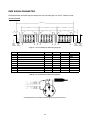
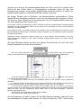
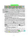
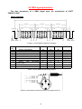
DMX SIGNALPARAMETER
Die Zeitparameter des DMX-Signals entsprechen den Anforderungen von USITT "DMX512/1990"
ZEITDIAGRAMM
PACKET
"FRAME"
9
"FRAME"
3
2
4
"FRAME"
3
7
4
3
7
4
9
7
1
IDLE
BREAK
LINE
OR
"MARK" RESET
1
START CODE
5
DIMMER 1
6
8
5
DIMMER N
6
8
5
6
A Figure 1 for the DMX512/1990 timing diagram.
DESIG
1
2
3
4
5
6
7
8
DESCRIPTION
"SPACE" FOR BREAK
"MARK" BETWEEN BREAK & START
FRAME TIME
START BIT
LEAST SIGNIFICANT DATA BIT
MOST SIGNIFICANT DATA BIT
STOP BIT
"MARK" TIME BETWEEN FRAMES
PACKET TIME
PACKET REPEATITION EVERY
MIN
88
8.00
43.12
3.92
3.92
3.92
3.92
0
49
TYP
88
44.0
4.0
4.0
4.0
4.0
0
22.67
50
MAX
90
10
44.48
4.08
4.08
4.08
4.08
2
51
TABLE 1 for the DMX512/1990 timing diagram.
Correspondence of contacts of the plug stereo jack and XLR-3.
27
UNIT
µSEC
µSEC
µSEC
µSEC
µSEC
µSEC
µSEC
µSEC
mSEC
mSEC
IDLE
BREAK
LINE
OR
"MARK" RESET
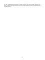
SERVICE PANEL DESIGNER
(Projektorvorlageneditor)
Dieser Editor soll zur Erstellung von Servicepanels dienen
Steuerungssoftware zur Projektorsteuerung zu benutzen.
und
dazu,
diese
innerhalb
der
Es gibt 2 Möglichkeiten zum Anlegen eines Servicepanels:
1. Laden Sie ein zuvor erstelltes Panel, verändern Sie es nach Ihren Wünschen und speichern Sie es unter
einem neuen Namen ab.
2. Erstellen Sie ein neues Panel.
Zuerst müssen Sie die Anzahl der vom Gerät verwendeten DMX-Kanäle eingeben. Als
nächstes müssen Sie eine Maske der verwendeten Kanäle erstellen. So belegt z. B. der
Projektor «DATAMOON» von NJD 4 DMX-Kanäle, aber Kanal 2 ist nicht belegt oder der
«CC-150» von Futurelight – der 4 DMX-Kanäle belegt, aber nur einen benutzt - «Nummer
4». Bitte cklicken Sie auf das Kästchen des entsprechenden Kanals im Fenster «Mask of
used channels», wenn er belegt ist und deaktivieren Sie das Kästchen, wenn der Kanal
nicht belegt ist.
Im Feld «Device name» können Sie den Projektornamen eingeben. Dieser Name wird dann zur
Identifizierung des Projektors von der Software verwendet. Diese Namen lassen sich im Fenster «Setting of
DMX channels» unter der Überschrift «Type of service panels» betrachten. Als Namen können Sie den Typ
und die Marke des Gerätes eingeben.
Wählen Sie danach das zu verwendende Symbol für den Projektor aus (dieses Symbol
wird im Fenster Plan angezeigt). Sie können auch Ihr eigenes Symbol mit jedem Bitmap28
Programm wie z. B. Microsoft Paint erstellen. Die Symbolgröße muß 32*32 Pixel betragen
und darf 16 oder 256 Farben haben.
Die Toolbar-Leiste der verfügbaren Werkzeuge sieht wie folgt aus:
Sie können jedes Element der Toolbar auswählen und auf ein leeres Formular des Service
Panels clicken. Jedes Element hat seine eigenen Eigenschaften. Die folgenden Elemente
sind verfügbar:
1. Container
- zusätzliches nicht aktives Element, das dazu verwendet werden kann eine Gruppe von
Steuerelementen von anderen Elementen zu trennen. Darin enthaltende Elemente können mit der Maus
im Hauptfenster bewegt werden. Eigenschaften: Links, oben, Breite, höhe, Container-Überschrift, Farbe,
Schriftart. Bevor Elemente in den Container gelegt werden können, muß der Container mit der linken
Maustaste ausgewählt werden.
2. Pan/Tilt Panel
- aktives Steuerelement zur Pan/Tilt-Steuerung von Scannern oder Moving-Heads
mit dieser Funktion. Die Positionen im «Pan/Tilt Panel» können mit der Maus angewählt werden.
Eigenschaften: Links, Oben, Breite (fix), Höhe (fix), Pan-Kanalnummer, Tilt-Kanalnummer. Die
Eigenschaft «Has two sizes» wird dazu verwendet, dieses Feld zu halbieren. Wenn Sie diese
Eigenschaft auf «True» ändern, wird es so angezeigt. Drücken Sie dann die «TEST» Taste und clicken
Sie mit der rechten Maustaste auf das «Pan/Tilt panel», und das Element wird groß. Drücken Sie
nochmals auf die rechte Maustaste und das Element wird klein. Diese Eigenschaft kann verwendet
werden, wenn kein weiteres Steuerelement mehr plaziert werden kann.
Wenn Sie im Arbeits- und Testmodus des Programms die «Ctrl» Taste drücken, wird die horizontale
Bewegung gesperrt und wird die «Shift» Taste gedrückt können Sie die vertikale Bewegung sperren.
3. Farbtaste
- aktives Steuerelement um einen einzelnen Wert eines bestimmten DMX-Kanals
einzugeben. Eigenschaften: Links, oben, Breite, Höhe, DMX-Kanalnummer, eingebener Wert, Farbe.
- aktives Steuerelement um einen einzelnen Wert eines bestimmten DMX-Kanals
4. Mustertaste
einzugeben. Eigenschaften: Links, oben, Breite, Höhe, DMX-Kanalnummer, eingebener Wert, Muster
(kann auch mit «Paint» erstellt werden, s.o.) Sehr nützlich für Gobos, Strobes und andere Events.
- aktives Steuerelement zur Steuerung variabler Parameter des gewählten DMX5. Knopf-Taste
Kanals innerhalb eines Intervalls. Eigenschaften: Links, oben, Breite, Höhe, DMX-Kanalnummer,
Minimalwert und Maximalwert. Die Farbe dient nur zur Dekoration und wird nicht benötigt.
6. Vertikaler Fader
7. Horizontaler Fader
- gleiche Funktion wie Knopf-Taste.
- Variation, s. o.
- nicht aktives Steuerelement, das zur Eingabe von Textkommentaren auf dem Panel
8. Text symbol
verwendet werden kann. Eigenschaften: Links, oben, Breite, Höhe, Beschriftung, Farbe, Schriftart,
Transparent.
Nach der Positionierung auf dem erstellten Panel kann jedes Element über die Maus oder durch Drücken
der «Shift» Taste und den Pfeiltasten in jede beliebige Größe gezogen werden. Es läßt sich löschen durch
Drücken der «Delete» Taste (die Löschung eines Containers löscht alle enthaltenen Elemente). Durch
Drücken von «Ctrl/D» können Sie das gewählte Element kopieren.
Das Kästchen «Snap to grid» aktiviert die Gitternetzlinien.
Das Kästchen «Locks Elements» verankert das Element auf seiner Position.
In der Liste «Control element list» können Sie die Gesamtliste aller Elemente des Panels einsehen.
Sie können eine Vorlage für jeden Kanal erstellen, indem Sie in dem Panel «Mask of used
channels» wählen und den Wert (-1) einstellen, der nicht definiert bedeutet. Außerdem
läßt sich das Ziel «Aim of channel» auswählen, wenn Sie über Pan/Tilt-Steuerung
29
verfügen ist es sinnvoll, die entsprechenden Kanäle auf «Pan» und «Tilt» zu stellen. Dann
können Sie den «Track editor» im Hauptprogramm verwenden. Wenn Sie über eine
Farbsteuerung verfügen, ist es nützlich, das Ziel diese Kanals auf «Colour» zu stellen, etc.
Diese Einstellung wird im «LOGICAL MASTER» Modus verwendet.
Mit einigen Geräten gibt es Probleme, vom Blackout-Modus zurückzukehren. Dieser
Modus läßt sich kanalweise definieren in dem Sie den Blackout-Wert eingeben. Drücken
Sie dazu die Taste «BlackOut» im Haupprogramm und die Projektorkanäle senden den
von Ihnen bestimmten Wert (außer «0»).
Durch «Start channel» und Drücken der «TEST» Taste könen Sie Ihre Projektorvorlage im Realtime-Modus
überprüfen mit dem tatsächlichen Gerät und Sie können auch die Kanäle auf dem «Control Elements
Properties» Ppanel betrachten.
Das Textfeld im Panel «User Defined Control Panel Header» wird im Hauptprogramm verwendet, um die
benutzerdefinierten Überschriften verschiedener Geräte desselben Typs zu positionieren. Bitte verwenden
Sie dieses Feld niemals.
Alle«Device service panel(.dsp)» Dateien müssen sich in dem «Device» Ordner befinden, um für die
Steuerungssoftware verfügbar zu sein. Nicht benötigte Projektorvorlagen können aus diesem Ordner
entfernt werden.
Mit etwas Phantasie können Sie auch Ihre eigenen Panel kreieren, die zwei oder mehr
einfach Projektoren auf einem Panel enthalten.
Die Liste "Control Elements List“
ist sehr hilfreich wenn Sie kontrollieren
möchten ob sie zwei Elemente auf die gleiche Position gelegt haben oder außerhalb des Bildschirms.
In der Liste „Channels list“
können Sie die ganze
Liste der belegten Kanäle sehen.
a) Sie können für jeden Kanal aus der Oberfläche „Mask of used channels“ einen Vorgabewert
definieren.
b) Außerdem können Sie die Auswahl „Aim of channel“ vornehmen, wenn Sie über Pan/Tilt Steuerung
verfügen. Diese ist hilfreich, um die entsprechenden Kanäle auf „Pan“ oder „Tilt“ umzustellen.
c) Sie können den Blackout-Wert für jeden Kanal eingeben. Dies ist z. B. hilfreich für bestimmte
Lampen, die sehr lange Zeit benötigen, bis sie erneut gezündet werden können. Füllen Sie dazu das Fenster
„Black Out State“ aus. Die eingegebenen Werte werden dann an das Gerät ausgegeben, sobald die
Blackout-Taste gedrückt wird.
d) Sie können den Vorgabewert für jeden Kanal einstellen.
e) Sie können den Smooth-Status definieren.
Um die Projektoren zu testen, müssen Sie die DMX Adresse festlegen. Geben Sie dazu
die Startadresse im Fenster „Start channel“ ein. Durch Drücken der „TEST“ Taste können
30
Sie die Vorgabewerte des aktuellen Gerätes im Real-Time Modus testen. Schalten Sie
Ihren Projektor and und verbinden Sie seinen DMX-Eingang mit dem DMX-Eingang des
Wizard-Interface.
31
DMX Wizard 512
A. Introduction
B. What’s new in 4.1X version
C. Making a SHOW
D. Control Panel Designer (Light fixture template editor)
E. The contents of the package, getting connected
F. Problems
32
A. Introduction
ATTENTION!!! To avoid electronic damage make sure that all DMX-fixtures and the
computer are unplugged (from power) when you make DMX-connections!
The program is intended for discotheque lights management. The main features
are simple learning and high-speed control of different types of light fixtures using
the upgradable control panel library for the most popular light fixtures. That carries
out a friendly interface for controlling a lighting fixture with image buttons. This
buttons contain specific images (colors, gobos). One of important elements on a
control panel is Pan/Tilt - field for controlling the movement of the beam (it is also
possible to control using traditional sliders). The control of light fixtures is
provided through the DMX interface, which is connected to computer through the
printer port (LPT).
Main features:
1. The program can operate any light fixture, which has a DMX interface.
2. It can control any amount of light fixtures located on 512 DMX channels.
3. SHOW consists of up to 256 SEQUENCES, SEQUENCE has up to 16384
SCENES. The quantity of SHOW files is unlimited.
4. Each light fixture can have its own customized template (control panel),
including color buttons and gobo pictures.
5. Traditional light software options - Pan/Tilt swapping and reverse, MultiSequence mode and so on.
6. Synchronization is possible from internal and an external source of
sound. It is also possible to control the show via MIDI, including sequencer
software etc.
7. Opportunity to redirect light fixtures to manual override at any moment of
SHOW actions.
8. Super fast addition of a new light fixture to the previously created SHOW
due to convenient operations of copying and editing.
9. The library of control panels (light fixture templates) can be extended by
using the included panel designer (see chapter D Control Panel Designer).
10. The program is designed for Windows 95/98 using a screen resolution of
800x600 or higher.
(C) 2001
B. What’s new in 4.1X version
33
Favourite button has 16 variations, which can be prepared preliminary.
Favourite button can be quickly reassigned from one variation to another
during the SHOW when necessary (see chapter C18).
In Play List «New string» and «Delete string» commands can be
provided by the buttons (see chapter C13).
Now the software is compatible with Windows 2000 in demo mode.
Menu structure is changed.
Panel Designer is accessible from the main window (View menu, popup menu, Fixtures menu and a button). Fixture pop-up menu has "Open at
Panel Designer" command. You can quickly improve wrong panel, save it,
and return back to SHOW.
Help can be recalled from Dmx Setup window.
Some grammatical mistakes are improved.
Improved name window bug: when turning back from Panel Designer
to Main window.
Some dialogs were renamed: "Position memory" to "Pan/Tilt update"
and "Smooth" to "Crossfade".
Load dialogs for SEQUENCES and fixture SEQUENCES now reflect
information about quantity of SCENES and quantity of channels (for fixture
SEQUENCES).
DSP files are associated with Panel Designer PROPERLY.
Hot keys can be unassigned (neutralized)
"Master OFF" button now is on the Additional toolbar. It is also active
for Yellow Master.
«Fixture OFF» command can be neutralized now with «All Fixtures
ON» command.
«Open» and «save» folders are memorized separately in *.cfg file for
all kinds of operations.
34
C. Making a SHOW
1.Beginning
2.SHOW Structure
3.Creating a SEQUENCE
4.Playing sequences, playing SHOW
5.The copying of SCENES
6.Monitor, Sliders, Plan
7.List of Sequences
8.Choosing a light fixture and setting its attributes
9.Possible master modes
10. Fixtures Pop-up Menu
11. Additional Toolbar
12.Multi-Sequence Player
13.Play List
14.Media Player
15.Synchronization, MIDI and Hardware
16.The files and settings toolbar
17.The “Black Out” button
18.The Favorite button
19.Values/Tempo Editor
20.Beam Track Editor
21.Pan/Tilt Update
22.DMX channels setup
23.Hot Keys Assignment
24.DMX signal parameters
35
1. Beginning
Attention! If when starting the software you have received the message «DMX device is
inaccessible», please read the chapter E. The contents of the package, getting connected.
The software shows the following dialogue on start up:
To create a new SHOW press «Create a new SHOW»
button, then you
will be asked to configure the DMX patch (see chapter C22), here you can add and
remove the various light fixtures to be used in your SHOW, then you need to enter
the name of your first SEQUENCE:
.
If you want to work with an earlier created SHOW press «Load a show»
button and you will see the standard dialogue for opening the show file.
Later for opening the last edited show use «Load a last show» button. SHOW file
can be also opened right from the Windows Explorer with double click on it.
We described how you could start creating and changing the SHOW. But if you
want to start from creating control panels (light fixtures’ templates) see steps below.
The «Control Panel Designer» button
opens the «Control Panel
Designer» (see chapter D). See the appropriate section of the manual for further
information. Panel Designer can be also opened with double click on a Control
Panel file (*.dsp extension).
36
If you want to return back to Windows and don’t open «DMX Wizard 512»
program for now, press
button.
2. SHOW Structure
1. SHOW consists of a set of SEQUENCES. Each sequence has name and index
number. It is possible to give original name to any sequence.
The SHOW name can be changed in the SHOW panel:
There is
no any associations between show name and show file name. In this version you
can not use Hot key letters in the SHOW name in this field.
2. The creation of a new SEQUENCE begins by pressing the
button.
Making it first time creates sequence number 1. The name of the SEQUENCE can be
defined when creating it, or at any other moment of editing the SHOW. For this you
have to select «Sequences List» option from the «Settings» of main menu or press
F7. Then you can change name of any sequence from list clicking to correspondent
name with the mouse. You can not use Hot key letters for the SEQUENCE name in
«Sequences List» but you can do it using pop-up menu when you right-click on the
SEQUENCE name field
(Choose «Rename SEQUENCE» option). You
can also use «Rename» command from «Sequences» menu as well as Hot keys
(user defined).
To remove an unnecessary SEQUENCE use the button
SEQUENCES toolbar:
in the
You can also use «Delete» command from «Sequences» menu as well as Hot
keys (user defined).
The yellow label <<
>> with some number to the right of the SEQUENCE
name is the index number of the SEQUENCE in SHOW.
3. The SEQUENCE consists of a set of SCENES. Each scene has name and
index number inside of its SEQUENCE. The yellow label <<
>> with some
number on the right of scene name is the index number of a SCENE in SEQUENCE.
It is possible to give original name to any SCENE. The name of the SCENE can be
defined when creating it, or at any other moment of editing the SHOW. You can not
use Hot key letters in the SCENE name in SCENE name field
but
you can do it using pop-up menu when you right-click on the field (Choose
«Rename SCENE» option). You can also use «Rename» command from «Scenes»
menu as well as Hot keys (user defined).
The creation of a new SCENE begins by pressing the
button. If you have
chosen SCENE number 3 in 4-scene-sequence and press the
button, you have
new SCENE number 4 which is a copy of a SCENE number 3, and old SCENE
37
number 4 has new number - 5. By pressing
button in the «Scenes» toolbar
you
can
remove
an
unnecessary
SCENE which is chosen at the moment.
The term SCENE can be explained as a statement of your light fixtures at each
special moment of time (just after DMX date of scene was transferred).
If SEQUENCE contains more than one SCENE, during editing you can go from
one SCENE to another by pressing the buttons
(«Next» and
«Previous»). Don’t forget that the result of previous scene edition can be refreshed
only before pressing one of this buttons. You can also use «Next» and «Previous»
commands from «Scenes» menu as well as Hot keys (default «Ctrl» + «A» and «Ctrl»
+ «Q»).
3. Creating a SEQUENCE.
The most convenient way of creating a SEQUENCE is the following:
a) Press the «NEW SEQUENCE»
button. You have a SCENE number 1
created along with new sequence.
b) Edit the first SCENE by setting all the involved light fixtures to necessary
positions and attributes desired for this SCENE. Press necessary buttons on the
control panels and change beam positions (pressing a «Ctrl» key, while cursor is
over Pan/Tilt field locks horizontal movement of a Pan/Tilt target, and pressing a
«Shift» key - locks vertical movement).
c) Press the «NEW SCENE»
button. Thus the following SCENE will inherit
the settings of the previous. Select the light fixtures to be in the next SCENE and set
the positions and attributes. Saving of settings in a SCENE occurs by pressing the
«NEW SCENE»
button or
buttons, or by choosing another
button. Before saving the scene, the
SEQUENCE, or by pressing «Play»
SCENE can be restored to the original settings by pressing the button
(«Refresh
Scene»). You can also use «Refresh» command from «Scenes» menu as well as
Hot keys (default «Ctrl» + «R»).
If you to make a quantity of same SCENES at once, make right click on the «New
SCENE»
button. Then you will see «Making new scenes» dialog
38
. Type in SCENES quantity and press «OK».
d) Thus by pressing the «NEW SCENE»
button and setting light fixture
positions and attributes and then saving, the SCENE can be created and the
SEQUENCE can be expanded. By pressing the «NEW SEQUENCE»
button
and then actions described above, the SHOW can be created and expanded. At any
moment we can return back to any SEQUENCE and add or delete some SCENES in
it.
You can also use «New» command from «Sequences» menu as well as Hot keys
(user defined). You can use «New» command from «Scenes» menu as well as Hot
keys (default «Ctrl» + «N»).
Any SEQUENCE can be saved on a disk and loaded from a disk by choosing
«Save Sequence» or «Load Sequence» option from the pop-up menu
(right-click by mouse on the SEQUENCE name). You can also
use «Save» command from «Sequences» menu as well as Hot keys (user defined). If
you choose «Load Sequence» command (the loading process doesn’t delete any
other SEQUENCES, i.e. it is going in insert mode), you will see the next dialog
. In
the right part of this dialog you can see information about chosen file: SEQUENCE
name and quantity of SCENES.
Any SCENE can be saved on a disk and loaded from a disk by choosing «Save
Scene» or «Load Scene» option from the pop-up menu
(rightclick by mouse on the SCENE name). You can also use «Save» command from
«Scenes» menu as well as Hot keys (user defined).
Splitting and merging of SEQUENCES.
In «Sequences» menu you can see «Split» and «Merge» commands. «Split»
39
command can be used for dividing of current SEQUENCE into to ones. The current
SCENE is a split-point (it becomes the first SCENE of second division). After
choosing «Split» command you will be asked for the name of the second daughter
SEQUENCE
(the first daughter SEQUENCE will have the
same name as mother SEQUENCE). SCENE names don’t change after splitting.
«Merge» command is used for merging 2 SEQUENCEs into one. If you choose
«Merge» command the current SEQUENCE becomes merged with the previous, but
the result SEQUENCE name is as it was in a previous SEQUENCE. SCENE names
don’t change after merging.
4. Playing sequences, playing SHOW
When you need to try your show you can play current SEQUENCE pressing
«Play» button
on transport bar
. To stop the performance at
. The default Hot key for
the current SCENE you need to press «Stop» button
both operations is «F12» and it can be user defined, but anyway it have to be the
same key for «Play» and «Stop». You can see that the light fixture control panel is
changing during play (beam position, marked buttons, turning knobs and so on).
The same situation is when you are changing SCENEs manually while program is
being in edit mode (when stopped).
There is also possibility to play a SEQUENCE physically while virtual editing of
any SEQUENCE. To do the job you have to right-click by mouse on the «Play»
button and take «Play Current Sequence in Background» option. This option
provides background playing.
ATTENTION!!! Background playing is not activated in DEMO mode!!
In normal mode when you right click on the «Play»
Sequence
In
Background»
command
button, «Play Current
can
be
activated
. After choosing this command, «Play» button
starts blinking with red color
. But in DEMO mode «Play Current Sequence In
Background» command is disabled
.
During background playing the SEQUENCE (SEQUENCE which was chosen
while background start), all light fixtures have the same performance as while
40
ordinary playing. But control panels' changes can be caused never by the played
SEQUENCE; they can change only as a result of virtual editing. If you press «Start»
and then «Play» your playing mode becomes ordinary (you can double press
«F12»).
To the right of the transport bar, below the SEQUENCE number there is «Cycle
Sequence» button
, which is also a transport controlling element. When pressed
it «Cycles» the current SEQUENCE so that while playing after the last SCENE
SEQUENCE is started again. It happens as long as «Cycle Sequence» button is
pressed. When it is released SEQUENCE stops just after the last SCENE.
«External Synch»
button is used for switching of the synchronization mode.
When it’s yellow, external synchronization from the external sound source is
provided. External synchronization parameters can be defined as described in
Synchronization, MIDI and Hardware (see chapter C15).
When it’s blue
the synchronization from tempo track (see chapter C19) is
provided. When it’s green
, internal beat generator, which frequency is controlled
and highlighted in the frequency window
, trigs SCENEs switching. It is also
possible to control BPM (beat per minute) frequency by tapping on the «Manual
.
Tempo Correction» button
See also «Multi-Sequence Player» (see chapter C12).
5. SCENES copying.
The
button copies a SCENE into the buffer. When pressing it, you can
and
buttons appear in the «Scenes» toolbar. You can
see that the
insert a SCENE copied to the buffer after any other chosen scene of any SEQUENCE
by the «Insert» button or replace any chosen SCENE by the «Replace» button. You
can insert the copied SCENE after any chosen SCENE of any SEQUENCE with
button (the following SCENES change numbering for ...+1). You can also
button (the following
replace any SCENE with the copied SCENE using
SCENES have the same numbering) You can also use «Copy» command from
«Scenes» menu as well as Hot keys (default «Ctrl» + «Ins»).
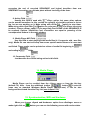
6. Monitor, Sliders, Plan
On the top left side of the main window you can see 3 tabs: «Monitor», «Sliders»
and «Plan».
«Monitor» tab window shows values of the light fixture channels in digital
decimal form and also the user defined headers of the light fixtures’ panels.
41
«Sliders» tab window shows the light fixtures channels values «in digital form»
and corresponding sliders (you can change the value of any channel by moving
those sliders).
«Plan» tab window shows your devices as icons with their user defined
headers. You can move these icons with the mouse and place them in the correct
location on the plan image. (Don’t forget to «unlock icons» in the «Settings» menu).
The Image for the plan window can be prepared with any graphics editor (as
Microsoft Paint etc.) and saved in 16- or 256-colors mode. You can replace the plan
image with your own painted picture through the «Change plan image» option of the
«Settings» menu.
7. List of Sequences
The list of sequences is used to allow fast selection (by clicking) of the
required sequence during SHOW playback and in editing mode. You can recall
sequence list from the «Settings» menu or by using Hot key (default «F7»). Next
pressing of «F7» closes the list of sequences. You also can use the additional
.
toolbar
, button
You can change the order of SEQUENCEs in the List of Sequences using
drag&drop operations. It can be done only when stopped.
If you operate with Sequence List when your Multi-Sequence Player is open (see
chapter C12), you can see that Sequence List turns into Multi-Sequence map. You
can fill check boxes, controlling which SEQUENCE is playing in which player. It was
made for more rich choice of operation. If you close Multi-Sequence Player, MultiSequence map is turning back into the Sequence List.
42
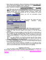
8. Choosing a light fixture and setting its attributes
You can choose a light fixture for control by mouse clicking on the green light
fixture header in the «Monitor» tab screen:
, also the same in the
«Sliders» tab screen, or you can click on the light fixture icon in the «Plan» tab
screen:
.
Then the heading of the chosen light fixture should turn dark green
, font turns white, and the corresponding light fixture template
(control panel) will appear to the right side of the tab screen.
You can control the attributes of a light fixture (pan/tilt for the beam of a scan,
color, gobo, etc.) by changing position of sliders in the «Sliders» tab screen, or by
typing in digital decimal numbers in edit text boxes of the «Monitor» tab screen. The
easiest way is to control the light fixture from its control panel to the right side of
the plan by pressing buttons and by using other types of user controls. The light
fixture template (control panel) can look like this one:
User can construct these light fixture templates (control panels) with template
designer (see chapter D).
The way of light fixture templates (control panels) designing can be learned by
exploring the ready ones attached to this software.
You can see two buttons
in the left-top corner of the panel. Selecting
sets selected light fixture into the defined «BlackOut» state, and
sets it into the
defined «Default» state. «BlackOut» and «Default» states values can be defined in
43
the Control Panel Designer (see chapter D).
9. Possible master modes
Each light fixture can work in one of the following master modes:
1.NORMAL - «green mode»
This is the usual mode of light fixture, in which, during the playback, the light
fixture is following the commands contained in SCENES and SEQUENCES and
changes its positions and attributes from one SCENE to another SCENE due to
current tempo, the tempo track or beat detector. When the playback is stopped or
when see Playing sequences, playing SHOW (see chapter C12), you get the
opportunity to control the device manually and to change any SCENE.
2.LOGICAL MASTER - «red mode»
«Logical Master» consolidates all light fixtures having the same templates
(control panels), in one master group. You can switch on this mode by clicking on a
fixture’s icon at map or header at other tab windows with mouse while the "Ctrl" key
pressed. Doing this first time sets all selected light fixtures in «Full Master» mode.
Different kinds of «Logical Masters» can be selected from submenu:
Choose "Master for Fixtures Group" of the context pop-up menu (click rightmouse button on the fixture’s icon), and then, one of submenu options. When you
select one of «Logical Masters» from that submenu all light fixtures having the
same template join this group selected for this kind of «Logical Master». You can
unselect all the (same panel) group choosing
option in the same
submenu.
Choose
option of the submenu, if you want to control all possible
features of the group being selected via one control panel.
option of the submenu, if you want to control only «color»
Choose
channels of the group being selected via the control panel.
Choose
option of the submenu, if you want to control all channels
of the group being selected via the control panel, except for Pan/Tilt channels.
Choose
option of the submenu, if you want to control only Pan/Tilt
channels of the group being selected via the control panel.
44
All channels of the group being selected this way, which are not controlled by
«Red Master», are involved in the SHOW as in a «Green Mode».
You can unselect some of the light fixtures by clicking on them by mouse
while holding «Ctrl» key. If you then choose a light fixture with «Logical Master»
already defined, while holding «Ctrl» key, the last defined kind of «Logical Master»
will operate. You can unselect all «red» fixtures pressing
«Master Off»
button to the right of the main menu, which appears only when some units are used
for «Red» master.
The «Logical Master» mode has 2 unique features:
a) During playback the «red selected» light fixtures are fully or partly
disconnected from current show control. They execute some or all commands
from the light fixture template (which is the same for all selected light fixtures).
This allows manual control of a group of the same light fixtures during a show.
You can have VARIOUS types of «red» fixtures simultaneously, but you can
control from one panel only the same kind. If you have chosen some light
fixtures in «Red Mode», you can change their separate attributes from the
«Sliders» tab window or from the «Monitor» tab window. Click on the
correspondent header and make necessary changes during playback or editing.
The rest of same kind «red» fixtures are not changing their parameters in this
case, like they do, if you are doing the same from control panel.
b) During editing mode the common light fixture template for the group can
change the attributes of the current SCENE. There is not faster way to change the
same parameter for same fixtures at once, than «Red Master». Thus it is possible to
use «Red Mode» for group editing of the show. If you need to make the same
changes in a group of the same light fixtures, the best way is to do it in a «Red
Mode», using common light fixtures’ template.
Though «Red Master» has not its own channel map, like the «Yellow» one has (see point
C9.4 «Physical Master»), you can use the «Yellow Master»’s map for disconnecting of some
separate channels from the «Red Master» control. For this you need to click twice on the
correspondent red cell on the «Yellow Master» channel map.
It
is
also
useful
to
know,
that
,
,
and
commands of the Additional pop-up menu (see chapter C10) are disabled for «red»
light fixtures.
3.MANUAL - «Blue Mode»
The mode is only for full manual control both during playback and when
stopped.
Switching on or off the MANUAL mode is provided by holding «SHIFT» key on
the keyboard when clicking on the light fixtures’ icons at map or on its header at
other tab windows. The icons or headers become «Blue».
The attributes of a «Blue» light fixture can be changed by all available ordinary
ways. In this mode the light fixture follows only manual commands. If you made
light fixture «Blue» it never follows the programmed show until you make it «Green»
again. But some of the fixture’s channels can appear to be under «Yellow Master»
control (see chapter C9.4 «Physical Master»). You can use «Blue Master» in
45
EDITING MODE only for MODELING, because changes made for «Blue» light fixture
can not be memorized.
Though «Blue Master» has not its own channel map, like the «Yellow» one has
(see point C9.4 «Physical Master»), you can use the «Yellow Master»’s map for
disconnecting of some separate channels from the «Blue Master» control. For this
you need to click twice on the correspondent blue cell on the «Yellow Master»
channel map.
4.PHYSICAL MASTER - «yellow mode»
This mode is only for manual control from special sliders. In this mode you can
assign the control of some defined DMX channels to one of 8 sliders of Physical
MASTER window. You can open Physical MASTER window choosing option
«Physical Master» from Settings menu. Channels assigned to the Physical MASTER
are disconnected from show control. It is possible to use up to 8 master faders,
each of which can control any quantity of DMX channels. From the moment of
becoming «yellow» these channels have a high-level status and can be changed
only from the Physical MASTER window.
On the Physical MASTER window there is a «View Table»
button,
which you have to press for defining of the configuration and channel map revision.
After pressing it you can see all 512 channels as a cells. Current mouse «cell
, which shows the
position» is indicated in the channel indication window
channel number of cell available for pointing by mouse at the moment. Gray cells
mean free (from any light fixtures) channels, busy channels are presented with
colored cells. Green cells mean channels controlled by SHOW, red - the ones
controlled by «Logical Master», blue - channels controlled by «Manual Master». To
assign some DMX channels to one of 8 Physical MASTER faders you have to
choose correspondent fader and then to choose correspondent cell (channels). The
chosen cells become «yellow» and you can see a fader number on it. To remove
«the yellow control» from a channel you have to click on correspondent cell again
one or two times (double-clicking is necessary when you do it while not
correspondent 1-8 fader is active). By the way one time-clicking on a «blue» or
«red» channel removes its depending on the correspondent master.
The main «MASTER» fader can be used for synchronous moving of all checked
faders (pay attention on check boxes over 1-8 faders). You can not assign or
unassign channels when the «MASTER» fader is chosen.
46
When starting a new SHOW all light fixtures are in NORMAL MODE («green»). In
further steps fixtures’ status can be memorized in SHOW file.
10. Fixtures pop-up Menu
It looks the next way:
You can reach the menu by pressing the right mouse button on the heading of
the chosen light fixture in the «Monitor» or «Sliders» tab window or on an icon in
the «Plan» tab window.
That allows you to provide various operations:
1. To copy the attributes of the single selected light fixture at the current SCENE
into the buffer, please choose «Copy Fixture Scene» command of the pop-up menu.
This command is disabled for «red» fixtures (see point C9.1).
2. To replace the copied attributes of the single selected light fixture into the
current SCENE, choose «Paste Fixture Scene» from the pop-up menu. This
command is disabled for «red» fixtures (see point C9.1).
3. To copy the behavior of one selected light fixture within the current
SEQUENCE (i.e. all fixture’s attributes in a chosen range SCENE by SCENE within
the current SEQUENCE) into the buffer, you have to choose
command of the pop-up menu. This command is disabled for «red» fixtures (see
point C9.1)
Then you see the next dialog:
This dialog allows you also to save the selected fixture’s behavior within the
defined SCENE range of SEQUENCE into a file with *.sqd extension. To carry out
this action press «Save to file»
button.
You also have possibility to define the first (
option) and the last
(
option) SCENE of the range being copied within the SEQUENCE,
which is active at the moment.
4. To replace the behavior of one selected light fixture within some SEQUENCE
for the behavior previously copied to the buffer. To carry out this action you have to
command of the pop-up menu. Please note, that no
47
additional SCENE’S will appear in the SEQUENCE, paste operations are used here
only in replacement mode. This command is disabled for «red» fixtures (see point
C9.1)
After choosing the command you can see next dialog:
This dialog allows you also to replace the selected fixture’s behavior within the
defined SCENE range of SEQUENCE with behavior loaded from a file with *.sqd
extension. To carry out this action press «Load from file»
that
you
can
see
the
next
button. After
dialog
. In the
right part of this dialog you can see information about the chosen file of fixture
SEQUENCE: the name of file, quantity of SCENES and quantity of channels.
You also have possibility to define the first (
option) and the last
(
option) SCENE of the fixture SEQUENCE range having been copied,
it means, that in some cases we don’t need to replace for all the copied or the
loaded range, and so we can make the limitation.
5. To switch the light fixture into «Solo» mode you have to choose «Solo»
command of the pop-up menu. In this case all light fixtures except the selected one
are switched off («BlackOuted»).
6. To select all identical light fixtures for the control from the one common
control panel. All light fixtures having the same kind of control panel can be
assigned to «Red Master» simultaneously. For that please choose «Master for
Fixture
Group»
option
of
the
pop-up
menu
and
some
of
its sub-options
(See
«Possible master modes» chapter C9).
7. To display the Track Editor (see chapter C20) if the device has Pan/Tilt-facility,
you have to choose «Track Editor» option (it is active only for fixtures having
48
Pan/Tilt) of the pop-up menu. The «Track Editor» will open with the chosen light
fixture set as active.
8. To display the Values/Tempo Editor (see chapter C19) for editing of the
SEQUENCE Tempo track or for executing of some copy/paste operations in digitalgraphic view, you have to choose «Values/Tempo Editor» option of the pop-up
menu.
9. To disconnect the selected device by setting all its channels to «Black Out»
state and making it independent of the following playback of the SHOW, you have to
choose «Fixture OFF» option of the pop-up menu. To restore all fixtures disabled
with the help of «Fixture OFF» command, choose «All Fixtures ON» command.
11. Additional toolbar
At the top of the main window, bellow the main menu and main bar, you can see a
ruler with buttons, which can open various screens. All this buttons are dubbed
with commands from the «View» menu.
«Monitor», «Sliders» and «Plan» are names of alternative fields, which are left lower
parts of main window
«Monitor» button - opens a field, which shows fixtures’ user names and
their channel values, which can be edited (see details in chapter C6).
«Sliders» button - opens a field, which shows List of fixtures’ user names
and field with sliders, which can control DMX channels. (see details in chapter C6).
«Plan» button - opens a field, which shows user’s map with fixtures’ icons
and user names, which can control DMX channels. (see details in chapter C6).
«V/T Editor» button - opens a field replacing all lower part of the main
window, which has 2 main modes-editors, DMX Value editor which can change DMX
channels values, and Tempo-Track editor which can change intervals between
scenes (see details in chapter C19).
«Track Editor» button - opens a high priority window with Beam Track
Editor, managing a beam’s trajectory as a geometric figure (see details in chapter
C20).
«Media Player» button - opens and closes a high priority window with universal
player for media files (see details in chapter C14).
«Play List» button - opens and closes a high priority window with Time Play List
allowing to prepare various actions at exact moments of the show (see details in
chapter C13).
«Sequence List» button - opens and closes a high priority window with the List,
managing SEQUENCES’ order (see details in chapter C7).
«Multi Sequence Player» button - opens and closes a field replacing all higher
right part of the main window with 12 players performing various SEQUENCES
simultaneously (see details in chapter C19).
(see
«Master Off» Button can be seen only when some master modes are active
details
in
chapter
C9).
49
12. Multi-Sequence Player
If you want to mix special SEQUENCES controlling various features of your
light equipment, you need to use Multi-Sequence player. Some users also like to
prepare SEQUENCES for each kind of light fixture separately and then mix them in
Multi-Sequence mode. To recall Multi-Sequence player you have to choose «MultiSequence Player» option of the «View» menu or press
button from additional
toolbar
or press the Hot key button («F8» default) on the keyboard.
From this moment all editing functions are disabled. Before you start operations
with Multi-Sequence player, we would like to give some advises:
1. For trying Multi-Sequence player use very simple SEQUENCES first, for
example you can create SEQUENCE changing colors in your light fixtures,
keeping in mind, that all unused channels’ values are set to zero. Then you
can take any other SEQUENCES, in which all channels are used ordinary
way, and preset all the colored channels to zero. Mixing of these last
SEQUENCES with the color ones will give you the best example of MultiSequence player usefulness.
2. Managing SEQUENCES in Multi-Sequence player.
Every player of the Multi-sequence player always contains the list of all
SEQUENCES of your current SHOW. When you open Multi-Sequence player
first time since creating of a new show, you can see the name of SEQUENCE
number 1 in every of 12 drop down lists. Anyway only ACTIVE SEQUENCE,
which you see in the list window, is to be played in every definite player. To
make the sequence ACTIVE you have to choose its name from the drop
down list. If you push «Play»
button or the Hot key («F12» default),
when all players contain the same SEQUENCE active, you will see mostly no
difference, like if you use ordinary playing with «List of Sequences» (see
chapter C7). To feel the difference, try to choose various sequences from the
drop down lists. Then switch activation button «
» if necessary to
activate proper players. Activation button circle is white
when the
player is active.
3. Possible actions in the Multi-Sequence mode:
You can choose active SEQUENCES.
You can switch players «On» and «Off». All players «Off» mean
«BlackOut».
You can change «Cycle Sequence» « » option, uncycled means
playing SEQUENCE one time and stop on the last scene.
You can change synchronization mode. «Main»
, «Tempo Track»
and «External»
(from audio beat-detector). In «Main» synchro you can
change bpm (tempo) value manually (tapping is not available).
You can use «BlackOut» and «Favorite» buttons.
50
Note: Changing ACTIVE sequence when Stop doesn’t cause active
changes of the light picture till Play
is activated.
To exit from «Multi-Sequence Player» you have to repeat once more one of
actions, which you provided for opening it.
The main principle of sequence mixing provides choosing the max DMX
signal value from 12 (or less) same mixing channels of ACTIVE sequences.
Note: At this mode «Full MIDI control» is not supported, you can change only
active sequence number in chosen active player with using MIDI «Note On»
directive (see Synchronization, MIDI and Hardware chapter C15).
See also chapter F «Problems».
13.Play List
You need Play List for creating highly detailed and complicated show
synchronized with internal timer. To open Play List window you have to choose
option from the «View» menu or press
button from
or press hot key (default «F6»). After that you will see
additional toolbar
an active window, which, when opened first time, looks the next way:
Play List is a sequence of command strings which are numbered in order and
linked to time values which are exposed in
field.
To make new string press «Add item»
button.
To delete string which is active at the moment press «Remove item»
button,
which can be enabled when you have not less than 2 strings.
Play List can be saved on disk with the help of «Save Play List»
button. To
start creating of new Play List press «New Play List»
button.
Saved Play Lists (files with *.pgl extensions) can be opened with the help of
«Open Play List»
button. In 4.11 version Play List is not included into the
SHOW file. Play List keeps the same even if you open various SHOWS
(including creating a new SHOW), if you don’t close the program. Don’t forget
to save your Play List on disk before closing the program.
Play List strings are always composed in order of start time progression. To
start playing from active string, press
button. To stop the performance
press
button. Active string which is at the process of execution is
highlighted with a color
.
1. Start Time Field.
It is important to know that Play List is starting right when button «Play»
is
pressed. Internal time is counting from the value exposed in start time field
51
from the first string or active string. If some string is active, after pressing
button, time starts running from the value exposed in that string, and the
action chosen in that string starts being provided. Strings are sorted
automatically so that later time has bigger order number.
2. Sequence Field.
Just choose necessary SEQUENCE from the drop down list. If you don’t need
any SEQUENCE play during this string action, keep or choose field
3.Multi-Sequence player number field.
When the numbers from 1 till 12 are chosen from drop down list, this option
causes Multi-Sequence Player to open and start with the corresponding player
enabled. This player will contain the SEQUENCE chosen in the Sequence Field,
and this player will be active (see chapter C12). If no number is chosen (or empty
filed
was chosen) the Multi-Sequence Player will be not activated. It
even becomes closed if it was open before.
If you need to start a few players (of the Multi-Sequence Player) at the same
time you need to create a few strings with the same time.
4. Tempo Field.
Has the same function as usual. In software version 4.11 the main Tempo
Field
on the Main Panel can correct tempo of SEQUENCE started
from the Play List right while its performance. It can be done by changing of
value in tempo field as well as tapping on
button.
5. Smooth Field.
Enables/Disables «Smooth» command (analog of «Crossfade» function)
during the string action, like as if you do it by yourself from «Settings» «Synch and Hardware» (see chapter C15) menu.
6. Synch Field.
Here you can choose the same types of synchronization as usual, like if you
use «Synchronization» button
(see chapter C4). Is used in ordinary and MultiSequence players. You need this field very much, for example, if you plan to start
midi file containing light show data controlling SCENES via virtual midi driver. In
this case don’t forget to take a look at
and
tabs of «Synch and
Hardware» dialog of «Settings» menu, because you probably may need to check all
involved parameters (see chapter C15).
7. Cycle Field.
Is used in ordinary and Multi-Sequence players. Uncycled SEQUENCE just
stops on the last SCENE. In the version 4.11 there is no way to start next string
except for timing (or «Goto» command). It means that the software can not
52
recognize the end of uncycled SEQUENCE and logical transition from one
SEQUENCE to another can not take place without involving of the timer.
8. Action Field.
Usually this field is used with
«Play» option, but some other options
can be needed sometime. In this version the quantity of possible options is not so
big, but we are working on it. Make string with «End»
option to stop timer.
Make string with «Goto NN»
option to cycle part of Play List (Enter low string
number). Choose «Stop» option, if you need only first SCENE of the SEQUENCE to
be exposed. Options «BlackOut» and «Favourite» are equal to pressing of the
correspondent buttons in the main window.
9. Media Player MCI Field.
Use this field to start playing some media files (4.11 supports .mid, .wav files
only). Media file can start and stop from some special marks between its own start
and finish. These marks can be pointed as a time of media file beginning in
and ending in
fields.
10. Comments Field.
Just describe the current string action in this field.
14. Media Player.
Media Player can be recalled from the «View» menu or from the Hot key
(default F5). Also - from the additional toolbar
, button
. It acts the
same way as standard Windows Media Player (Mplayer.exe). It can be also
background activated from the Play List (see chapter C13).
15. Synchronization, MIDI and Hardware
When you choose «Synch and Hardware» option from «Settings» menu or
make right click on
button you can see the following screen with various tabs.
53
1)The «Synch» tab. It describes various synchronization parameters,
including those necessary for the controller box autonomous job.
All parameters below this option are active only if the option is chosen and
«External Synch»
button is yellow. They are also important when you are
preparing the controller box for autonomous job (see point C15.5):
aa) Option
«Bit Detector Enabled». It turns on and off
the possibility of work with external sound source. It also switches 2
different programs (sound activated and Tempo Track activated) which
can be loaded into flash memory of the controller box (see point C15.5). If
you plan to work with U18 Control Board (see chapter E) or, for example,
to install the controller box for autonomous job with light fixtures at shopwindows, uncheck this option on the tab, so that your flashrom controller
will be programmed for tempo track SHOW.
a)
parameter determines how many SCENES will be
played after losing synchronization from an audio-source. Parameter
determines the range of available expected tempos on relation to
the chosen playback tempo displayed at the tempo window
of the
playback tool-bar. It means at setting «Drop down count» = 1 and «Range
%» = 90% the SCENES will be changed with any detected beat even with
very non-stable tempo, and at setting «Drop down count» = 100 and
«Range %» = 5 % they will follow each other not depending on the beat detector, but in accordance to preset playback tempo (look at your tempo
window
).
b) «In Pause» options.
«In Pause»
menu along with the "Pause for Change" (see
point d below) option allow to set the light fixtures behavior during long
period when no any signal is coming from the external beat - detector
(when there are some pauses between sound tracks). Accordingly after
expiration of "Pause for Change" time the light fixtures are switched to a
"Black Out" state or "Favorite" state or just pause (if «BlackOut» or
«Favorite» or «Stop» options are chosen).
54
c)
option.
Selecting "Randomize sequences" option provides a random change of
SEQUENCES in the SHOW after every sound pause while playback. If this
option is not active, every time when critical pause (see point d) is detected
the SEQUENCE will be replaced by the next.
If «Randomize Sequence» option is active, the computer makes
decision himself about the next SEQUENCE number after receiving first
beat while being in audio-pause mode. This allows the program control
the lighting on its own with no intervention from a light jockey. The major
importance of these options can be noted when using the controller box
separately from computer.
d) Minimum silence time, which can be recognized as a pause can be
chosen in
2)The «MIDI» tab.
window.
a) «Enable MIDI Remote Control» option
.
Choosing option "Enable MIDI Remote Control" allows assigning the
control of switching sequences and scenes from a MIDI source. All
parameters indicated below this option are actual only if the option is
chosen, and «External Synch»
button is yellow.
window. Gives a choice
b) «MIDI in Device»
possibility only if the option
is chosen. Use this
window to choose the device from which you will receive MIDI signals. The
most popular device is a MIDI keyboard attached to some PC MIDI port. But
some advanced users can use PC sequencer programs (like Cubase, Logic,
Cakewalk etc.) for creating combined music and light shows. To do that
you have to install virtual MIDI driver "MIDI Router" by "Sonic Foundry".
You
can
download
this
driver
on
http://www.sonicfoundry.com/Download/default.asp. Then you have to
address one of MIDI tracks of your sequencer to «X Sonic Foundry MIDI
Router» input, and use this track for recalling of necessary scenes
synchronously to the music (or for starting sequences). In this tab, in «MIDI
in Device» window you have to choose «X Sonic Foundry MIDI Router».
. Use this window for selecting the
c) «MIDI channel» window
55
controlling channel of your MIDI device. This channel will be used for
recording of SCENES or SEQUENCES depending on «Full control» option
(see point d).
d) "Full control" option
. The most effective
when used along with a MIDI Sequencer. When this option is selected all
play modes are canceled, i.e. show is in stop mode. Reception of the MIDI
instruction "Note On" (some note was «played») on the selected MIDI
channel will result in a change from the current SCENE to a SCENE with
number within the SEQUENCE, corresponding to number of the note (e. d
the note C0 will recall SCENE 1, note C1 will recall SCENE 2, and so on).
Reception of the MIDI instruction "Program Change" (Patch) will result in
change from the current SEQUENCE to the SEQUENCE with number
corresponding to number of the program (patch) in the midi instruction. If
there is not any "Note On" instruction simultaneously, the first SCENE of
the SEQUENCE is acting. Thus, in «Full control» mode, using an external
MIDI keyboard (or MIDI sequencer) it is possible to recall the scenes and
sequences (if that keyboard controls "Program Change") in stop mode. It
have to be obviously clear that «Crossfade» function (see point C15.3) can
not be active in «Full control» mode, because the software can not know,
when the next SCENE is expected.
. When this option is
e) "Sequences" option
selected all play modes are enabled, i.e. show is going on as well as usual.
Buttons "Synch" (any color)
, "Play"
and "Stop"
have same
results as without MIDI Remote Control. Reception of the MIDI instruction
"Note On" on the selected MIDI channel will result in a change from the
current SEQUENCE to the SEQUENCE with number corresponding to
number of the Note (e.d. the note C0 will recall SECUENCE 1). Any time
after changing, the new SEQUENCE position is «SCENE 1».
3. The «Crossfade» tab.
«Smooth» option
(equal to «Crossfade» function) enables
the mode of smooth switching (crossfading) between SCENES. Additional
conditions of the «Smooth» mode (choice of channels for crossfading) can
be defined when creating or editing of the light fixture control panel (see
chapter D «Control Panel Designer»).
«Smooth» function is strongly necessary for cheap scanners, applied
on Pan/Tilt channels forcing a beam of the scan to move smoothly (cheap
56
scanners have no speed control). Choosing «Line» option
enables
LINEAR crossfading from SCENE to SCENE. Choosing «Exp» option
enables EXPONENTIAL cross fading, which means growing up of
scanners' speeds when new SCENE is approaching. It is not so possible to
catch the difference between «Line» and «Exp» options if you have very
slow scanners.
Anyway «Smooth» option can be applied to any DMX channel of a light
fixture, for example to a dimmer channel, focus, iris and so on. But you have
to define it preliminary with the assistance of the «Control Panel Designer»
(see chapter D) capabilities.
4. «Hardware» tab.
It allows you to set base address of the printer port, to which the interface
box is connected. After setting address you should press «TEST»
button for updating data and testing the connection between your computer and
interface. After this procedure all DMX channels of the interface are reset to "0"
(physical Black Out). For restoring data on the channels please press button
«Refresh
Scene»
(Hot
keys
default
«Ctrl»
+
«R»)
or
buttons
.
5. The «Autonom» tab.
This tab has to be referred to for programming Flash-memory of the
controller version 3.5 and later. It will allow a possibility to use the box without
the computer with synchronization from an audio source or (for hardware
versions 3.7 and higher) from the tempo-track created on your PC. The order of
57
SEQUENCES and SCENES and change algorithms are also to be prepared and
loaded into Flash-memory from your computer.
Press «Programming» button
to load your show into the
controller box. Previously loaded show will be erased automatically. Don’t
forget, that this button is accessible and visible only when the controller box is
connected to your PC, while the box has hardware version 3.5 and higher. In
opposite case you will see the next description on the «Autonomus» tab.
If the box is connected properly you can see all previously defined details at
the «Autonom» tab. But to define them you need to open the «Synch» tab (see
point C15.1).
After loading, you can switch off and disconnect the computer from
controller (it is better to turn off the power of the box and the power of all DMXfixtures while disconnecting). The controller will play SHOW automatically in
accordance with the selected parameters. It is very important, which options
you have chosen in the «Synch» tab.
The main characteristics of loaded show (hardware version 3.5 or higher):
Quantity of sequences
up to 100
Quantity of scenes in sequence up to 255
Total capacity
2000 scenes
Number
of
reprogramming more than 10000
cycles
Time of programming 2000 ~ 7 minutes(0.2 sec/scene)
scenes
Order
of
playing
back random, sequential
sequences
The length of audio pause 2...120 sec
detected
Action in pause
stop, blackout, favorite
The "Autonom"
button allows you to set the controller into testing
autonomous mode. In the testing mode the first received audio beat starts up
the random numbers generator which will cause random order of SEQUENCES.
ATTENTION,
For users of hardware version 3.7 and later (flashrom version designed
from January 2000)
Autonom Sequence Playing from Tempo Track.
58
If you uncheck «Bit Detector Enabled»
check box in the
«Synch» tab you can see the new bold phrase in the «Autonom» tab:
It means that the controller will play sequences
according the tempo track (See chapter C19). The show will be cycled, i.e. the
last SCENE of the last SEQUENCE will be followed by the first SCENE of the
first SEQUENCE an so on.
This way of preparing of SHOW is also necessary for operation with U18
control board (see chapter E).
6. «AutoBackup» tab.
On this tab you can enable creating of a special file, named
«$AutoBak.dmx». Software will save a current show into this file according
to established time interval. In an abnormal situation you can restore results
of editing from this file.
16. The files and settings toolbar
All these buttons’ commands are duplicated with commands from «Files»,
«Scenes» or «Settings» menu.
The «New Show»
button (equal to «New Show» command from «Show»
menu) starts an empty new SHOW, closing the current SHOW. Pressing this button,
you immediately open
window with the DMX field the same as in
the previous show. A Hot key can be assigned by user (Default «None»).
The «Load Show»
button (equal to «Load Show» command from «Show»
menu) starts a dialog of loading of one of previously created SHOWS from the disk.
Hot key available (default «Ctrl» + «L»).
During playing back of the SHOW (in «Play» mode) you are allowed to load
another SHOW file without interrupt in playing, but in this case the DMX
configuration of the loaded show devices will not be checked. It will load only the
SEQUENCES and SCENES. Normal complete loading is possible only from «Stop»
mode.
The «Save Show»
button (equal to «Save SHOW» command from «Show»
menu) saves the current SHOW to the file on your disk with the old name (We mean
59
that you have opened the current SHOW from that file). Hot key available (default
«Ctrl» + «S»). If you save some new SHOW first time, this button’s action is the
same as for button «Save Show as..» (see description below).
The «Save Show as..»
button (equal to «Save SHOW As..» command from
«Show» menu) saves current SHOW to a new named file on your disk. You have to
choose this button for renaming SHOW, or for giving to SHOW file original name
first time. Do it to avoid deleting of previously designed SHOWS.
The «DMX channels»
button (equal to «DMX Channels» command from
«Settings» menu) calls on a window
for setting of DMX channels
(see chapter C22) and assignment of light fixtures, i.e. the window, where you
describe which light fixtures on which channels are, where you define their names
and reverse details. Hot key can be assigned by user (Default «None»).
button (equal to «Control Panel Designer»
«Control Panel Designer»
command from the «Settings» menu and «Fixtures Panel Editor» from the «View»
and «Fixtures» menus) recalls the software - creator of user’s control panels for
DMX fixtures (see chapter D).
«Refresh Scene»
button is placed to the right of SHOW name window. Its
destination was described earlier in chapter C3 «Creating a SEQUENCE». It cancels
all changes made in the current SCENE if you haven’t pressed any other buttons
after this changes, such buttons as
(default «Ctrl» + «R»).
etc. Hot key available
17. The “Black Out” button
The «BlackOut»
button (equal to «Black Out» option from «Operation»
menu) switches all light fixtures «off», according to settings made in their control
panels. The SCENE recalled with this button usually is aimed to turn off all possible
lights, but user is free to determine it for every light fixture «personally» (see
chapter D) This button also stops playing back SHOW if it is playing. Hot Key is
available (default «F11»).
If you need to turn some separate light fixture into the «BlackOut» mode, you
have to press a small button
in the top left of the fixture’s control panel.
18. The «Favorite» button
The «Favorite»
(is equal to «Favorite» option from the «Scenes» menu)
button recalls one of special SCENES which we name «Favorites». This button
stops playing back SHOW (temporary pause on the current SCENE). While the
button is gray, it means that no any SCENE is assigned to it. If you click by mouse
on the gray button it will have no effect. To activate the button and to make it green,
it is necessary to provide the next actions:
Variant 1. Right click on the «Favorite» button and choose «Select» command
60
from the pop-up menu
. Then you will see the next dialog
. If you have in your SHOW
some SCENES which you want to choose as favorites, you can select them without
closing the dialog, the same way as ordinarily in «Stop» mode. Then you need to
choose necessary string (Favourite 1, Favourite 2, ...) and press
button. Doing this we are filling one of 16 cells with various SCENES which in 4.11
version use to be dependent on their «sisters» from SHOW (don’t erase source
SCENES accidentally, otherwise the next SCENE will take place in correspondent
Favourite cell; the best way is to make last SEQUENCE consisting only of favourite
SCENES).
Now you need to assign some numbered Favourite to a main Favourite. For that,
just press
button while correspondent string is chosen. Thus, if we
will assign «Favourite 2» to the main Favourite and then press «Close» button, we’ll
be back in main window and Favourite button will look as
.
Variant 2. Choose
command from «Operation» menu or
press correspondent Hot key (Ctrl + F10 as default). The next steps are the same as
in Variant 1.
You can use
or
buttons to erase information from
one or from all cells.
Variant 3. If you have Favourite 1, Favourite 2 and so on, already assigned to
some SCENES, you can quickly assign the main Favourite button the next way:
make right click on Favourite button, and then make left click on the correspondent
string of the pop-up menu
.
Now you have chosen the «Favorite». At any moment of SHOW, press this
button
, which is green now, to pause SHOW and have this SCENE
immediately. Please note, that you will see no any changes at PC display (including
61
control panel) after recalling of «Favorite» SCENE (the result on display will be the
same as after pressing «Stop» button). Physically all light fixtures will show
«Favorite» SCENE, but the PC display will show you that you are in «Stop» mode at
some current SCENE. Hot Key is available (default «F10»).
19. Values/Tempo Editor
Values/Tempo Editor is intended for editing the information in a digital-graphic
implementation. Editing is available only in the limits of the current SEQUENCE. The
editor can be opened with «V/T Editor» command from the «View» menu or with
button from the additional toolbar.
The editor consists of two separate editors: "DMX Values Editor" and "Tempo
Track Editor". To toggle between those two editors you have to click corresponding
check boxes
on the context toolbar.
62
DMX values editor (choose option
).
In the "DMX Values Editor" it is possible to edit values of DMX channels
exposed graphically as columns. Each column reflects the selected channel’s DMX
value in some SCENE. The active SCENE is marked with a big cursor, the active
channel value in the active SCENE is exposed on the left above the ruler
.
You can choose active channel in the channel screen
(active is green) as well as you can choose active light fixture on the fixture’s
screen
.
Two editing tools are accessible: a pencil
and a ruler
. You can select
the required tool from the toolbar. You can use the pencil for pointing or drawing on
the column field. The value position of the pencil is exposed on the right above the
63
SCENE ruler
. Ruler
works like a «cut line». You need to hold left mouse
button while clicking on the first point and release it while clicking on the second
point, as the result you will see a range of columns growing or reducing linearly.
In this mode copying/pasting is also accessible. It is possible to pick up the
information for copying by two ways:
1.
a) Choose a part of the active light fixture sequence, including all the light
fixture channels.
Using the pointer tool
select a range of SCENE numbers using mouse
drag on the scene number ruler
. During the dragging
the chosen range data ix exposed on the right above the ruler
.The selected range is dark now. Then click the right mouse button on the
selected range.
b) Choose the item "Copy" from the pop-up menu
can see the dialog determining copying parameters
. Then you
.
2.
a) The other way allows involving only some range of channels and SCENEs,
which are next to each other, into copying operations. To do this, select the
channel value tracks required by mouse drugging
.
You choose a range of SCENES at the same moment. The selected range of
SCENES and tracks is dark now. Right click on the range.
b) Choose «Copy». In all other operations the two methods above are
identical.
After copying is made you can paste (it means «replace») this range from the
marker point. For paste it is necessary to set a marker on the required SCENE
number and to choose active channel (the copy data will not be pasted on the
channels with number less than number of active channel). Now you have to
right-click anywhere on the ruler. Then you can see the next dialog window
64
, at which you can’t define anything, only press «Ok» or
«Cancel»
The copy/paste commands are inaccessible while playing a SHOW.
In this editor the button «Refresh Scene»
works as one-level undo.
(Hot keys default «Ctrl» + «R»)
Clearing range.
If you proceed like in p. «a» then you can choose «Clear Selected» from the
pop-up menu
0.
. All channel values in the selected range will be set to
Filling range.
The information kept in the buffer after copying (see point a) can be used like
element pattern. If you choose range bigger than copied before you can fill it with
multiplied patterns copied just previously. For that you have to choose
command from the pop-up menu.
Tempo Track Editor (choose option
)
Tempo track is very interesting synchro option, which can be edited and
memorized for every SEQUENCE. If you select blue color of the synchro button
playing back will follow the edited SCENE times.
65
,
The first different feature, which you see after opening, is total SEQUENCE
time exposed on the right side of the SCENE ruler
. Pencil
and ruler
tools are also accessible, but on the right above the SCENE ruler, when using
these tools, the tempo value and the time value in the possible application point is
exposed
. All operations with pencil and ruler are identical to the same
operations in DMX values editor. Of course, selecting a light fixture has no effect,
because tempos are the same for all light fixtures and channels. On the left above
the SCENE ruler you can see tempo value for the SCENE, on which the big cursor is
positioned. Near between the brackets you can see also the time duration between
the current SCENE and the next SCENE
(interval), which is, of course,
inversely proportional to tempo value.
You can see time positions above some SCENE numbers on the SCENE ruler
. The first scene of time position is always zero. On the picture you can
see that a next nearest time position is exposed above the SCENE 9. But if you
press one time on big magnifying glass on the right or on the left of the bottom
scroller
, then the nearest time position will be under the SCENE 5
, i.e. the wider is SCENE ruler, the more time positions you see.
You can’t undo changes to the Tempo-track. SCENE range choosing, copying
and pasting is disabled.
66
20. Beam Track Editor
Track editor is intended for editing of the light fixtures’ beam positions. It can
be applied only for those light fixtures that have Pan/Tilt control. Track editor
window can be recalled one of 3 ways:
on the additional toolbar
1. By pressing «Track Editor» button
below the «Stop» button. If the momentary active fixture doesn’t have the
controlled beam facility and its control panel doesn’t have Pan/Tilt field,
pressing this button will cause the next note
.
2. First right-click on the fixture’s icon or header with mouse, then choose
«Track Editor» option
from the pop-up menu. This option is not
active for fixtures without Pan/Tilt field.
3. While you are in the Values/Tempo editor, right click on the fixture’s name
and then confirm «Track Editor» option.
4. From the «Fixtures» and «View» menus.
Once you have opened track editor you can see the active fixture’s beam
positions in all SCENES of the current SEQUENCE (or in selected range of
SCENES) as a light fixture's beam movement trajectory.
SCENE range can be changed in «From Scene»
Scene»
and «To
windows. It is also possible to right click on the
corresponding numbered SCENE point and select
or
command from the pop-up menu
. You can see that only points
from this range are visible (visible track). Choose
option of the popup menu to restore and make visible the complete range of SCENES from first
to the last. You can move any point (light fixture beam position) by selecting
the appropriate one on the field and moving the cursor while holding left
67
mouse button. You can also select a group of positions by selecting with
mouse by dragging a square zone containing them with mouse and then to
click on this zone once more and to move it into a new position while holding
left button.
Press «Resize» button
to resize the whole visible beam track
horizontally, vertically or both (changing X, Y parameters
and then
button).
button is used to cancel all changes in
pressing
trajectory since the moment of opening of the editor window.
Press «Rotate/Mirror» button
to execute rotation or reflect operations
applied for the whole visible beam track. Buttons
and
are for vertical and
horizontal mirror transformations relatively to the center of the track field (when
higher and lower or left and right points are exchanging). To provide whole visible
beam track rotation to the angle defined in the
window, you have to
press
button. Possible angle range is from -180 to 180 degrees. To avoid any
confusion we have to warn you that many times applying of the rotation will lead to
the common distortion of the beam trajectory because of multiplying of mistakes.
button is used to cancel all changes in trajectory since the moment of
opening of the editor window.
It is also possible to straighten the part of visible trajectory (i.e. the part
defined in
and
windows) by pressing the button
«Linearize»
and then
.
button is, as always, used to cancel all
changes in trajectory since the moment of opening of the editor window.
Press «Polygon» button
to achieve a triangle (vertex 3), a square (vertex
4), a pentagon (vertex 5), and a hexagon (vertex 6). You can define «size» parameter
in
window if necessary. It can be changed from 4 to 254.
button
button is, as always, used to cancel all changes in
realizes trajectory;
trajectory since the moment of opening of the editor window.
Press «Circle/Curve»
button to make enclosed curve having 1-5 loops (15 factors). The curve view can be chosen in
window.
button
realizes the figure;
button is, as always, used to cancel all changes in
trajectory since the moment of opening of the editor window.
as well. It is very
You can use very convenient tool "Sewing machine"
simple to «sew» a fixture’s beam positions SCENE by SCENE, clicking on the field
by mouse. SCENES are counting automatically in the limits of visible range, and
when the range is over, the editor automatically exits «Sewing Machine» mode.
During the «sewing» all other light fixtures are acting like when simple switching of
SCENES. If you need to cancel the results of «sewing», you need to press
button as usual.
68
If you open track editor during play back, results of corrections are visible right
away.
Use magnifying buttons
to change track field size.
69
21. Pan/Tilt update
This feature is very good for mobile show users.
Pan/Tilt Update can be described as some template keeper. These templates are to be
used in live shows. To be more correct, the Pan/Tilt Update editor is keeping not only the very
DMX information but the list of SCENES, which need to be updated as well. The most
important is the fact, that Pan/Tilt Update editor enable not only 32 typical SCENES
(templates) memorizing (beam positions only), but also making changes in this templates and
updating all their clones by pressing one button. At the same time all changes concern only
beam positions (the rest of the SCENES-clones DMX data can be absolutely different, it will
be not changed anyhow). When you move with your show to new place (with different venue
and the trim height of the truss) and fixtures' beam positions in some important scenes have
to be different, all you have to do is trim the position templates to the correct location. All the
SCENES and SEQUENCES, registered in the Pan/Tilt Update editor, will be easily updated
using the position templates.
«DMX Wizard 512» has 32 position memories (templates) into which you can store
Pan/Tilt position for all the devices (the same way as it is stored in complete SCENE
information). Unfortunately in the current software version there is no any possibility to
choose some separate light fixtures for position updating. It means, all SCENES registered in
the same Pan/Tilt Update template must have the same beam positions of ALL light fixtures.
To understand how it works we can offer some example.
Let us have 10 scenes in our SHOW which have the same beam positions, and this
positions are very important for us because the beams have to highlight people standing on
the stage. When we settle from place to place, we have to adjust all this positions in all
SCENES, but other components will stay the same (colors, gobos, and so on). To correct
beams every time in every SCENE is good idea but not the best. It is much easier to assign all
this 10 scenes to Pan/Tilt Update SCENE number 1. How we do it is:
a) Choose command
from «Settings»
menu. This has to be made only at first address to «Pan/Tilt Update» editor in the
current SHOW, after erasing of all position templates (choosing command
). After that, «Pan/Tilt Update» window will
open, close it till it will be needed.
b) Switch one of the 10 SCENES. Right click on the SCENE name.
c) Choose
command from the pop-up menu. Then you see
the next dialog window
.
d) Set «1» in the template number window because we want all our 10 SCENES be
clones of the template number 1 (in other words we want to register or assign
them with template number 1
e) Carry out the same actions for all 10 SCENES.
f) Choose
options from «Settings» menu.
We can see «Pan/Tilt Update» window with light fixtures list and Pan/Tilt field.
70
g) If SHOW is currently at one of our 10 SCENES we can import all beam
positions from this SCENE into the template number 1. We choose tab «1» in
button.
«Pan/Tilt Update» window. We press
h) Now we have all the beam positions in the template number 1 exactly the same
as in the current SCENE, but we can make changes in the template choosing some
light fixtures and correcting their beams. Though we see all corrections made on
Pan/Tilt field of the «Pan/Tilt Update» editor, they won’t touch the current SCENE
parameters neither physically (real fixtures’ beams will keep standing in one position)
nor virtually (in the current SCENE’s memory), till the moment of the next step. If
we now close the «Pan/Tilt Update» editor, all changes made inside the editor’s
Pan/Tilt fields will be kept only in it.
e) We press
button to correct all 10 scenes at once. If it is necessary exit
the «Pan/Tilt Update» editor, make VISIBLE editions of the current SCENE
Pan/Tilts and pass again from the step «f».
To remove the current SCENE from Pan/Tilt Update registration (assignment), choose
command from the pop-up menu with right click on the SCENE
name.
To change the Pan/Tilt Update template number assigned with the current SCENE, choose
command from the same pop-up menu.
In more complicated shows there can be more «Scene - sisters» «families» for quick correcting
(we can serve up to 32 «families»!). All «sisters-SCENES» of one «family» have to be assigned
to one «Pan/Tilt Update» template (with the same number). If we have more than one
«family», and we have got new positions for all of them, we can correct all scenes from all
«families» at once by pressing
button. Please note, that it is not possible to correct
only some light fixtures, while the other of light fixtures stay the same.
You can use
buttons, which has the same functions as
buttons for toggling between SCENES within the current SEQUENCE, while you are in
«Pan/Tilt Update» editor.
71
22. DMX channels setup
The window for setting DMX channels appears automatically at start of a new
SHOW, or by pressing the
button in the main window of the program. The same
results can be achieved choosing
menu.
option from the «Settings»
In the middle of this window you can see the list of available light fixture control
panels (templates).
You can select and then drag & drop any device from this list into the «DMX
channels field».
You can also move any light fixture mask into a new place of the «DMX channels
field» by drag&drop operations.
NOTE: if you use this method to change DMX address of fixture used in an
EXISTING SHOW all SCENES and SEQUENCES will update so that corresponding
DMX data of SHOW will move to the new DMX address.
If your light fixture is not listed in the light fixture list then you have to place the
necessary *.dsp file to the Devices folder. You can take this file from the device
library included in the package (see chapter E). Device library is always being
extended in our web site http://www.futurelight.de. If you can not find the necessary
fixture template, try to use Control Panel Designer (see chapter D)or you can order it
separately free of charge (we are interested in expansion of supported devices
library). You can contact us on of the next ways: e-mail: Gerhard Spiegel,
[email protected] or through web site. If you want us to make a good
quality control panel for you, please supply us with all the necessary information
about your light fixture (gobo pictures, DMX protocols and so on).
In
field of
zone it is possible
to enter any user information, which will be displayed on the fixture’s icon and on
the fixture’s headers in the
tabs of the main window.
To the right of the user header you can see three check boxes
.
They are very important for humanization of the Pan/Tilt controls depending on the
light fixture’s orientation.
a) If your light fixture is oriented by its back side to the operator (light-jokey),
you don’t need to mark any of those check boxes because beam movement
will agree with the mouse movement.
b) Now let us imagine that your fixture is oriented with its beam to the operator,
i.e. any movement of the mouse will cause opposite (reversed) movements of
72
the beam. In this case you need to mark check boxes
and
to
coordinate the mouse and the beam movements.
c) The fixture is oriented with its right side to you, i.e. the beam is shining from
left to right. In a certain sense Pan and Tilt have «traded places». This event
as well as such function has name «swapping». To coordinate beam with
mouse you need to mark check box
. Now you will find out that Tilt
movement is reversed to mouse. To compensate this you need to mark check
box
as well.
d) The fixture is oriented with left side to operator. «Swapping» is also
necessary here, i.e. you need to mark check box
. Now you find out
that Pan movement is reversed to mouse. To compensate this you need to mark
check box.
An image of the DIP switches
is shown to make easy to set
DMX addresses of the light fixtures. The picture is corresponding to the switching to
channel, under which the cursor is. The channel number is highlighted in the
. Please, keep in mind, that some fixtures can
channel window
have additional switches, which are not exposed on the picture. At the same time
some other fixtures can have less switches (i.e. not all channels are available), and
some can have alternative reference between switches and channels. For details
see your fixture’s user’s guide.
Pressing the button
configuration.
The button
saves a chosen configuration as the default
clears all occupied channels and clears all user headers.
The button
recalls «Control Panel Designer» (see chapter D). Use it if
you need to edit or design some of control panels. If you have designed a new one it
will be immediately in the list of devices, if you saved it in the Devices folder. Close
«Control Panel Designer» and you will see it (as you will appear in «DMX setup
fixtures» window).
73
23. Hot Keys Assignment
To correct or assign Hot keys you have to choose
option from
the «Settings» menu. Then you will see the «Hot Keys Assignment» window.
You can use any standard key combinations as a Hot keys, except for ones used
by Windows. For example you can not use «Alt» + «Esc», «Alt» + «Tab», «Ctrl» +
«Esc», «PrtScr», «Alt» + «PrtScr» or «Alt» + «Space».
To remove a Hot Key assignment press
Hot key is highlighted.
74
button, when the necessary
24. DMX signal parameters
The time parameters of a DMX signal meet the requirement of USITT
"DMX512/1990".
TIMING DIAGRAMM
PACKET
"FRAME"
9
"FRAME"
3
2
"FRAME"
3
4
3
4
7
7
4
9
7
1
1
IDLE
BREAK
LINE
OR
"MARK" RESET
START CODE
5
DIMMER 1
6
8
5
DIMMER N
6
8
5
6
IDLE
BREAK
LINE
OR
"MARK" RESET
A Figure 1 for the DMX512/1990 timing diagram.
D
ESIG
1
2
3
4
5
6
7
8
DESCRIPTION
"SPACE" FOR BREAK
"MARK" AFTER BREAK (MAB)
FRAME TIME
START BIT
LEAST SIGNIFICANT DATA BIT
MOST SIGNIFICANT DATA BIT
STOP BIT
"MARK"
TIME
BETWEEN
FRAMES (MBF)
PACKET TIME
PACKET REPEATITION EVERY
MIN
TYP
MAX
UNIT
88
8.00
43.12
3.92
3.92
3.92
3.92
0
88
44.0
4.0
4.0
4.0
4.0
0
90
10
44.48
4.08
4.08
4.08
4.08
2
µSEC
µSEC
µSEC
µSEC
µSEC
µSEC
µSEC
µSEC
49
22.67
50
51
mSEC
mSEC
TABLE 1 for the DMX512/1990 timing diagram.
Contact correspondence between the stereo jack plug and XLR-3.
75
D. Control panel designer
(Light fixture Template Editor)
This software part is intended for constructing of light fixture control panels.
These light fixture control panels (light fixture templates) are necessary for using
them within «DMX Wizard 512» software for faster management of light fixtures.
If you are creating or playing show at the moment, to open the Control Panel
Designer you have to close «DMX Wizard 512» application first. Then you have to
start «DMX Wizard 512» again. On the start dialog press the "Fixture Template
Editor"
button. The more fast, though less evident way to open the
editor is to open it through the «Setup DMX Fixtures» window, which can be opened
from the main program window any of ways mentioned in chapter C22 «DMX
channels settings». While you have this window opened you need to press
button. In this case when editing or creating of panels is over, after
closing of «Control Panel Editor», you will return back to «Setup DMX Fixtures», and
your SHOW will keep loaded.
There is also two more ways to open the Panel Designer:
button on the instrumental toolbar,
-with the help of
-via the right click on a fixture’s icon on the plan in the main window, and
further choosing of
option from the pop-up fixture menu (in this
case the Panel Designer will be opened right with the panel active at the moment).
The first you will see after loading is the next window:
There is also an empty field for control elements to the right from this window.
There are two ways of constructing:
1.Load a previously created panel, change it to your needs and save with a new
76
name. We have to note here, that you can not find «save as..» command in the
«Panels Designer», because the command «save» always means «save as..» here.
command from «File»menu or you press
I.e. if you choose
will recall «Save as..» dialog anyway:
button, you
One of inconveniences when creating one panel from another is possible loss of an
element when moving it from one place to another. We hope to fix this problem in
future versions (an element falls under the container, and the only way to see it over
is to delete it and create the new one).
2.Create new panel from zero. A possibility to open two «Panel Designers» at once
seems to be convenient here. Of course, you can not move ready elements from one
editor to another, but at least you can open some ready panel in one editor and,
looking on it, to create something close in another. Don’t forget about possibility to
save button images to files and to load them into another buttons when making new
panels.
Now let us to describe the very process of panel creating.
First you have to set number of DMX channels used by the light fixture in
window (correct by arrows).
Let us investigate the channel field
.
The next step is setting the mask of your light fixture channels, particularly
choosing active and non active channels of the fixture. For example: the light fixture
named «DATAMOON» by NJD occupies 4 DMX channels, but channel number 2 is
not used for the light fixture control, as well as «CC-150» color changer by Future
Light - it occupies 4 DMX channels, but uses only one - «number 4». Please mark
check boxes for the channels used by the light fixture in the
remove mark of unused channels.
You can also choose the aim of channel at the
77
column and
window. If you have
Pan/Tilt control, it is correct to set the aim of corresponding channels to «Pan» and «Tilt».
You are then allowed to use «Track editor» (see chapter C20) in the main program. If you
have color control it is useful to set the aim of this channel to «Color», etc. This setting also
can be necessary for «LOGICAL MASTER» mode.
field. When you create new SEQUENCES in a SHOW, channel
Then we fill
values in the first SCENES of new SEQUENCES are as exposed in this field first.
Those values will be also set on the channels when pressing
button on the top left of
control panel in the main program.
field is very important for panels designing. If you don’t define
Filling
«BlackOut» state of a light fixture in this field, all its channels will be set to 0 when pressing
button or
button in the main program. But some light fixtures need careful
treatment when you set them in «BlackOut» state. For example in some fixtures powerful
lamps can be switched off, when you set all channels to 0. Then you need to wait up to 20
minutes to switch those lamps on. At the same time you can remove all lights without
switching lamps off. For intelligent treatment you need to describe «BlackOut» value for each
channel. To do this set values in «Black Out State» field, choosing channels one by one.
Those values will be sent to the light fixture when pressing
main program.
and
buttons in the
The next field,
, regulates the questions of fading or, in other words, the
questions of soft conversion from one SCENE to another in some separate
channels. Mark those channels which have to change between SCENES smoothly
when
Hardware»).
option is chosen (see chapter C15 «Synchronization, MIDI and
Then you have to load the previously created icon using
button.
You need this to create recognizable image of the light fixture as you will see this
icon in the
tab window in the main program. You can draw this icon with
any bitmap editing software, like «Paint» by Microsoft. Size for this icon must be
32*32 pixels and 16 or 256 colors bitmap or «ico» format. After pressing this button
you will see
dialog. Browse and choose necessary image. If you
want background to be visible (not gray), mark bottom left pixel of image with any
different color.
In the
field you enter the unique fixture’s name that will be
used later for identification of the light fixture by «DMX Wizard 512» software. You
can view this name then in the
window, «Available fixtures list»
78
screen (see chapter C22 «DMX channels settings»). As a name you can use the
fixture’s brand name and it’s manufacturer. .
The toolbar of possible control elements looks as follows:
You can select any element on this toolbar and click on the empty form of the
constructed control panel to have the element on the panel. Each element has its
own properties. Every element can be placed on the control panel, and then it can
be tested with the help of
button or «Test» command from the menu
tool be
«Mode». To highlight an element already placed on the panel you need
active.
If you have chosen one of the elements placed on the panel, you can toggle to
any other element using keyboard arrows (left and right). To move element over the
panel you can use all 4 arrows, while holding «Ctrl» key. To change an element’s
size, you can use all 4 arrows, while holding «Shift» key. Though, you can do the
screen, correcting values in the correspondent
same right in
windows. . By pressing «Ctrl» + «D» you can duplicate a selected element with all its
properties.
Now we describe available elements:
1.Container
- decorative element, it can be used to separate a group of
control elements from other elements. It is very important to know that all other
elements can be placed only on the container, which is activated at the moment,
when you create any new element. If no any container is activated (just click on an
empty field), it is the only way to put a new element on the field directly. At least, if
) and
you don’t see a new created element, just try to delete it (use
then create it again with some container activated. If you delete container (press
DEL button when the container is activated, or use
command from the
«Edit» menu), you delete all elements created during its activity. Elements placed in
the container can be moved with their container selected, across the field using
drag&drop operation. Don’t forget that it is impossible to move elements from one
container to another, from any container to field and from filed to container.
Container has its header (caption), which is often used to make description for
elements. Properties (reflected on
Height, Caption - header of container, Color, Font.
field): Left, Top, Width,
2.Pan/Tilt Panel
- active control element for Panorama/Tilt control of scans
that have this function. Properties:
Left,
Top,
Width (fixed),
Height (fixed),
Pan Channel number,
Tilt Channel number,
Pan Fine Channel number (if
chosen),
option on
79
field is
Tilt Fine Channel number,
16 bit option, Half Size option.
Property
is used to reduce this field size in two times. When you
work with the half size Pan/Tilt, you can see that mouse resolution is twice more
detailed, when the cursor is under the Pan/Tilt field. Please note, that resizing of the
element’s contour has no any effect, but there are some other possibilities. If you
press
button and right-click on the half-sized «Pan/Tilt panel», you will see
that the size of this element becomes large. Some elements which were around the
Pan/Tilt field are still visible, but some not. It should be useful to place no any
container near of the half-sized Pan/Tilt field, because the container is always above
all other elements. Click right mouse button once again and see that the size of
panel becomes small. You can use this property if there is no space for positioning
of another control elements.
property allows using «Pan/Tilt panel» for controlling scans with
«Coarse» and «Fine» channels for Pan and Tilt beam movement. When you use 16bit Pan/Tilt field «Coarse» and «Fine» channels are used simultaneously for exact
targeting. If you choose this option you can see a dotted line below the panel, it
allows to set a «movement resolution» for mouse. It is possible to adjust «default
movement resolution», which will be exposed in the main program. For saving a
panel with selected «default movement resolution» you have to press
button, then to select necessary resolution and to save the panel. After assignment
all of 4 channels you can try to move a target of this element and to see that speed
of mouse movement changes with different settings of «movement resolution».
Pressing «Ctrl» key, while cursor is over the Pan/Tilt field in main window in the
«DMX Wizard 512» software and in a «TEST» mode of the «Panel Designer», locks
horizontal beam movement of a Pan/Tilt target, and pressing «Shift» key - locks vertical
beam movement.
3.Color button
- active control element. It can be used to set a definite
value on the selected DMX channel. Properties:
,
,
,
,
, assigned value that has been set on the channel
, color of
circle on the button. You can choose the color from the Windows color palette,
using
button. When you press it, you can see the next window
80
.
It
can
look
different if you use 256 colors or 16 color mode. You have to know that using high
color palette for color knobs takes more resources from your PC when you load the
control panel in the main program. We recommend using 256 color mode palette
because panels made in it will go mostly in any case. In the end, when you have the
window), you press «OK» to finish.
color chosen (it is indicated in
4.Image button
- active control element. It can be used to set a definite
value on the selected DMX channel. The image buttons are mostly useful for
switching gobos, strobe effects and for any other events. Properties:
,
,
,
,
,
,
assigned value that has been set on the channel
image on the button. You can load image from file to the image button, using
button.
If
you
do
this
you
will
see
the
next
dialog
. The
file have to be in bitmap format, image size have to be not bigger than the button
size (see width a height properties). To remove image from the button press
. If
you want the image background to be visible (not gray), mark bottom left pixel of
image with any different color.
Caption on the button
. If you have image loaded on the button,
the caption will be placed below the image
81
. To define caption font size and
color press
button and make necessary adjusting.
5.Knob
- active control element to control variable parameter on the
,
selected DMX channel within determined interval. Properties:
,
, minimum Value
and maximum Value
,
,
, knob’s color.
You can choose the knob color from the Windows color palette, using
button, doing it the same way as for color button (see point 3).
6.Vertical fader
above).
- the same as Knob, but has different shape (see the point
7.Horizontal fader
- variation of the same item.
8. Color/Density Control element (CMY)
.
It looks the next way on the control panel:
. This element
can be used in new advanced scanners and color changers which have 3 special
channels Cyan channel, Magenta channel, Yellow channel. CMY element allows to
control the beam’s color and density continuously by mouse, not controlling every
of the 3 channels separately. It is accessing the 3 channels simultaneously.
Properties:
,
,
,
,
,
,
.
9.Text label
- decorative element, it can be used for entering text
comments on the panel.
Properties:
,
,
,
.
Text. Can be changed in
window.
Label color. Can be changed the same way as for color button (use
see point 3). In the «Transparent» mode label color is not visible.
Font. Can be changed the same way as for image button (use
point 4).
Transparence. Can be chosen in the
color of label is disabled, if «False» - enabled).
,
, see
window (if «True» -
Check box
allows you to match elements’ position and size on the
panel to the special grid 8*8 pixels. Matching is happening when you change
82
element's properties any of possible ways. Mark this check box, if you want to set
all values divisible by 8.
Check box
locks the elements in their positions. It is equal «Lock
elements» option from the «Edit» menu. If you have finished elements positioning
and start channel values setting, this option can be very useful.
You can choose element clicking on it, using arrow keys or choosing it from
the «Control Elements List»
. It is very useful if you want to check,
whether you’ve placed two elements at the same position or some elements out of
the screen.
For testing light fixture with the new designed control panel or for testing some
new designed element press
button. When pressed it turns into
button, which need to be pressed when tests are finished. Before that you need to
set light fixture’s DMX address. DMX address means number of the first fixture’s
channel, which you fill in the
window. You can start «Test» mode also via
«Test mode» option from the «Mode» menu and return back to «Design» mode via
«Design mode» option.
Setting of «Start channel» and pressing the
button allows checking
your light fixture template in the real-time control mode. Turn on your light fixture
and connect its DMX input to «DMX Wizard 512» control box and you will see the
real job of elements on the designed control panel.
«Control
Elements
Properties»
field
describes all properties
of the chosen element. Properties are different for different elements (see «available
elements» of the «Device service panel designer»).
On
an
empty
panel
body
you
can
see
description
. Please, don’t recover this field with any
elements, because, in the concrete installation, the name, which you will give to the
fixture in
window (see chapter C22), is to be placed exactly instead
of this description in the main program.
All control panel (*.dsp) files must be placed into the «Devices» folder to be
available for using by the main «DMX Wizard 512» software. Light fixture templates,
which are not required, can be removed from this folder. Removing of unnecessary
files from the «Devices» folder will help your computer to keep additional power for
other applications.
83
With minimum imagination you can design your own panels with two or more
simple light fixtures controlled from one panel. For example you can control up to
32 Par lamp channels from one control panel (no need to have 32 light fixtures on a
plan).
At the same time you can need to split one panel into two for controlling one
device from two panels. It can be useful when you have big Pan/Tilt library (see
point C10.3 «Save Fixture SEQUENCE»), and you want to use it for various brands
of scanners.
84
E. The contents of the package, getting connected.
The package (hardware version 3.7U) consists of:
1. Controller box (3 XLR DMX outs, line-jack and mic sound activation)
2. LPT-port connection cable
3. Installation CD disk
4. User’s manual
5. Package box
The package including remote control U18 consists of:
85
1.
2.
3.
4.
5.
6.
Controller box (3 XLR DMX outs, line-jack and mic sound activation)
Remote control desk U18
LPT-port connection cable
Installation CD disk
User’s manual
Package box
ATTENTION!!! To avoid electronic damage make sure that all DMX-fixtures and
the computer are unplugged (from power) when you make DMX-connections!
ATTENTION!!! The hardware controller of XLR-versions (hardware 3.1 and 3.7)
should be supplied from an external power supply with voltage DC 9V (any polarity).
Information for U18 control board owners.
At the moment there are just a few things which you are able to do with U18. It
allows mostly to change pre-loaded SEQUENCES on the way, while half of all
SEQUENCES which can be controlled (the first 16 from 32 can be recalled without
«Shift» button) work from external sound source, and half (the second 16 from 32
can be recalled while holding «Shift» button) work only from the pre-programmed
Tempo Track. Tempo track have to be programmed before loading the SHOW into
controller box memory. The first 32 SEQUENCES only can be controlled totally from
U18, though the control box can hold much more.
Then U18 has «Tap» button which corrects the tempo, but when you stop
tapping in couple of seconds the tempo is determined again by external sound
source (in the first 16 SEQUENCES) or by Tempo Track (in the second 16
SEQUENCES).
Generally, the process of preparing SHOW and loading it into the flash memory
for using with U18 is exactly the same as for Tempo Track SHOW (see description of
process in C15.5). If you have made the process properly and then start the box (to
start the box you have just to turn on its power), you can see that SHOW is going
permanently from the very beginning to the very end of the last SEQUENCE and
then again from the beginning to the end and so on while obeying the
tempos/intervals written preliminary. But, if you plug U18 to the box (using the same
LPT cable), the controller’s job is changing immediately and goes, as described
above, depending on the buttons of U18.
U18 precedence rule.
1. Turn off the power of the computer and turn off the power of all DMXequipment.
2. Connect controller box (version 3.7U and higher) to the computer through the
cable attached to the package. Connect the controller box to DMX-fixtures as
well.
3. Turn on the power of all equipment including computer and controller box.
4. Prepare SHOW which consists of 32 SEQUENCES. Some SEQUENCES, if
necessary, can hold only one SCENE for using them as «BlackOut» or
«Favourits». SEQUENCES from 1 to 16 have to be prepared to work with
external sound source (excluding those consisting of 1 SCENE). SEQUENCES
from 17 to 32 have to be prepared with obligatory revision of their Tempo
Tracks which can be corrected depending on your artistic styling.
86
5. Open «Synch» bookmark in «Synch and Hardware» dialog (see chapter C15).
Revise «Bit Detector Enabled» option, which have to be unchecked before
you start loading the SHOW into the controller box.
6. Open «Autonom» bookmark in «Synch and Hardware» dialog (see chapter
C15). Make sure that you see
inscription at that
bookmark. Without this inscription there is no reason to start loading the
SHOW because after such loading (without «Autonom Tempo Track
Sequence» inscription) the controller box will not recognize U18 remote
controller. Push
and
you
button, you will see confirmation dialog
will
. Push «Yes» button. The loading will starts
see
proceeding
indication
dialog
. Wait till the end of the operation.
7. Turn off the power of the computer, controller box and all DMX-equipment.
8. Unplug LPT cable from the computer and connect it to the U18 remote
controller.
9. After the pause necessary for lamp’s cooling (10-20 min), turn on the power of
the controller box and all DMX-fixtures. You have to see on the U18, that
button 1 LED is lighting. The button «Shift» LED is not lighting. It means that
at the moment SEQUENCE 1 is chosen and it plays from the external sound
source.
Hint: if you want SCENES to be switched manually only with «Tap» button,
not
responding to the sound, plug phone jack (without cable) into the
«AUDIO LINE IN» socket of the controller box.
10. To change SEQUENCES «on the fly» push corresponding buttons from 1 to
16. To change SEQUENCES from 17 to 32 use the same buttons while holding
«Shift» button which LED lights up.
If you need to make temporary correction of SCENE change rate push the «Tap»
button in the tempo you need. The tempo restores to its original Tempo Track
value or to external sound bit in 2 seconds after the last tapping.
Installation of the driver
If you are going to install «DMX Wizard 512» software on your computer for
the first time, you have no need to read the further information! For setting the
printer port base address you can read the chapter C15 «Synchronization, MIDI and
Hardware »
87
F. Problems
Using multisequence player, two sequences are clashing.
SYMPTOM:
When two sequences are active in play mode, you see that the pan/tilt or
colour or gobo effects are jamming, or you get restricted movement played
back, through your lighting fixtures. For example with MAD SCANNER
sequence playing and ROBOSCAN sequence also playing, both sets of lights
seem to have lost the ability to PAN and TILT properly – like there is a clash
or “jam”.
88
REMEDY:
This is a short term fix – if you encounter this problem whilst engaged in your
lightshow:
Turn off other active sequence using the ON/OFF button (which is a black or
white light next to the sequence name selector)
However this does not fix the problem – it is just a quick way to save trouble
if you are not able to stop show and go to edit mode!
THIS IS FULL FIX:
You must understand the concept of how a sequence stores data. Every
sequence stores the settings of every light told to in scenes. See V\T editor
info in your help files. Study how V\T editor works.
The problem of “Jamming” occurs when 2 or more sequences are trying to
control the same lights at the same time. You might not have realised that
you told the sequence editor to store this other light fixture scene data, but
you probably did… as I have done… many times!
Looked at another way, Sequence 1 has info for primarily Light 1 but has
managed to also picked up settings for light 2 which isn’t needed. Sequence
2 has info for Light 2 primarily but also picked settings for light 1. The two
sequences when played together clash or “Jam” against each other because
both are trying to force commands at the same time. Ofcourse, there can only
be one command sent to a light at any one time. The way the lights deal with
two commands being sent at once is to either go with one command, or to
not change light fixture settings at all.
Go out of Multisequence player back to Sequence Editor… the main screen.
Select V\T editor. Now select the SEQUENCE that has the jamming problem
(do the other jamming sequence later, using this same method). Select the
light fixtures that aren’t the ones you want playing in this sequence . One by
one, go through the channel info (click your mouse on) – ie: 1 = pan, 2 = tilt
3= gobo etc. If you see coloured channel info in the right hand data screen
then you need to get rid of that data. That data is causing the jam. The easiest
way to do this is to highlight the time bar – say scene 1,then scroll over to the
last scene, then you see the scenes selected. With your mouse cursor over
the selected area, press the right hand mouse button. Select CLEAR
SELECTED, and you see the confirm clear screen. Press OK. This should
now clear the scenes data for unwanted lights.
Note; Some people don’t see the clear confirm screen, if they have turned
this screen off previously, using the tick box!
Now you can go back and do the same for the other sequences that might
have conflict scene data. When you have finished clearing all scene data for
lights, exit the V\T editor using CLOSE. Save your project. Your show should
work now with no jamming.
89
WHY DOES THIS HAPPEN IN THE FIRST PLACE:
This seems to happen because when you program a sequence you have
selected another light, perhaps by mistake. This then causes the sequence
editor to store scenes with data for that light. Be careful in future to only
select light you are storing scenes for. Good luck.
90