1
D/A/CH
Bartscher GmbH
Franz-Kleine-Str. 28 , 33154 Salzkotten
www.bartscher.de
Bedienungsanleitung
für
Induktionsgeräte
105.840, A105.942, A105.943, A105.946, A105.948
A105.949, A105.952, A105.953, A105.954, A105.956, A105.957,
A105.935, A105.936, A105.937, A105.938, A105.939
A105.950, A105.958, A105.968, 282.410, 282.420
Seite 1 von 21
Ver.1.4
Bartscher © 2008
Inhaltsverzeichnis
Seite
1
1.1
Allgemeines
Anwendung
3
3
2
2.1
2.2
Produktbeschreibung
Produkte
Technische Daten
3
3
4
2.2.1. Bedienung und Kontrolle
2.2.2. Technische Gerätedaten
2.2.3. Funktionsbedingungen
4
4
4
Installation
Elektrische Daten der Geräte
5
3.1.1.
3.1.2.
3.1.3.
3.1.4.
5
5
5
5
3
3.1
Geräte nach Leistung (2,5 kW, 3 kW)
Geräte nach Leistung (3,5 kW)
Geräte nach Leistung (5 kW)
Geräte nach Leistung (7 kW, 8 kW)
3.2
3.3
3.4
Installationsvoraussetzungen
Installationsvorschriften
Installationsvorschriften für das Einbaumodell
6
6
6-7
4
4.1
Inbetriebnahme
Montage
7
7-8
5
Funktionstest
9
6
6.1
Bedienung
Kochprozess
10
10
7
7.1
7.2
7.3
7.4
7.5
7.6
7.7
7.8
7.9
Sicherheitsvorschriften
Beschreibung von Gefahren-Symbolen
Gefahren bei Nichtbeachten von Sicherheits-Vorschriften
Sichere Anwendung
Sicherheitsvorschriften für das Bedienpersonal
Unsachgemäße Bedienung
Änderungen / Gebrauch von Ersatzteilen
Pfannenerkennung
Überwachung der Heizzone
Geräuschentwicklung
11
11
11
12
12
13
13
13
13
13
8
Außerbetriebnahme
13
9
9.1
Fehlerfindung / Fehlerbehebung
Übersicht Fehlermeldungen auf Anzeige
14-15
16
10
Reinigung
17
11
Unterhalt
18
12
Entsorgung
18
13
Ersatzteilliste
19-21
Seite 2 von 21
Ver.1.4
Bartscher © 2008
1.
Allgemeines
Diese Bedienungsanleitung beinhaltet grundlegende Informationen die bei
Montage, Anwendung und Unterhalt beachtet werden müssen. Sie muss vor
Installation und Inbetriebnahme vollständig durch den Monteur und
Bedienpersonal gelesen werden, und immer zum Nachschlagen in der Nähe
Kochstelle aufliegen.
der
der
das
der
1.1 Anwendung
Die Induktions-Kochgeräte werden zum Zubereiten von Mahlzeiten eingesetzt.
Sie können zum Kochen, Warmhalten, Flambieren, Grillen usw. von Speisen
verwendet werden. Achtung, auf Induktions-Geräten muss ausschliesslich
induktionstaugliches Pfannenmaterial verwendet werden. Für den Einsatz des
Pfannenmaterials sollten keine NO-NAME-Produkte eingesetzt werden. Der
Pfannenboden muss magnetisch sein. Im Zweifelsfalle kann man dies mit Hilfe
eines Magneten testen.
2.
Produktbeschreibung
2.1 Produkte
BM-Modelle
.
A105.942, A105.943, A105.954, 282 410, 282.420,
BI-Modelle
A105.946, A105.948, A105.949, A105.952, A105.953, A105.956, A105.957
BW-Modelle
105.840, A105.935, A105.936, A105.937, A105.938
-
Kompakte Modulbauweise
-
Einfache Montage
-
Servicefreundlich
-
Einfache Bedienung mittels Drehknopf
-
Kompakte Leistungselektronik ermöglicht einfachen und sicheren Betrieb
-
Max. Betriebssicherheit dank diversen Schutz- und Überwachungsfunktionen
-
Kompakte Aussenmasse
-
Geringes Gewicht
Seite 3 von 21
Ver.1.4
Bartscher © 2008
2.2 Technische Daten
2.2.1 Bedienung und Kontrolle
Lampe „Betrieb bzw. Topferkennung“ 2V DC/ca. 10mA (LED rot )
Leistungsregler – Potentiometer
0Ohm – 10kOhm
Dimensionen
BxTxH
Ceranfläche
105.840
330 x 380 x 175 mm
Wok Schale Ceran
A105.942,.943,.954
340 x 420 x 100 mm
290 x 290 mm
A105.946,.948,.949
400 x 455 x 120 mm
350 x 350 mm
A105.956,.957
400 x 655 x 120 mm
350 x 560 mm
A105.952,.953
700 x 455 x 120 mm
650 x 350 mm
A105.935,.936,.937
400 x 455 x 180 mm
Wok Schale Ceran
A105.938
500 x 555 x 235 mm
Wok Schale Ceran
A105.950
400 x 400 mm
350 x 350 mm
A105.958
400 x 700 mm
350 x 650 mm
A105.968
700 x 700 mm
650 x 650 mm
282.410
400 x 700 x 860-900 mm
350 x 605 mm
282.420
800 x 700 x 860-900 mm
650 x 605 mm
2.2.2 Technische Gerätedaten
Geräte
Spannung
Leistung
Gewicht
105.840
1 x 230 V
3.0 kW
A105.942,.943,.954
1 x 230 V
2.5, 3.0, 3,5 kW
A105.949
3 x 400 V
5 kW
A105.946,A105.948
1 x 230 V
3.0, 3.5 kW
A105.937
3 x 400 V
5kW
A105.935,A105.936
1 x 230 V
3.0, 3.5 kW
A105.938
3 x 400 V
8 kW
19 kg
A105.950
3 x 400 V
5 kW
12 kg
A105.958
3 x 400 V
7, 10 kW
21 kg
A105.968
3 x 400 V
20 kW
40 kg
282.410
3 x 400 V
10 kW
50 kg
282.420
3 x 400 V
20 kW
80 kg
8,5 kg
9 kg
13 kg
11-13 kg
14 kg
11-13 kg
2.2.3 Funktionsbedingungen
-
max. Toleranz der Netzspannung Nominalspannung
+5%/-10%
-
Frequenz
50 / 60 Hz
-
Schutzklasse
IP 43
-
min. Pfannen-Durchmesser
12cm
Seite 4 von 21
Ver.1.4
Bartscher © 2008
3
Installation
3.1 Elektrische Daten der Geräte
3.1.1. Geräte nach Leistung (2,5 kW, 3 kW)
Induktionskochfeld 1-phasig (Spannung 230 Volt +5% / -10%)
Anschluss Farbe
Frequenz
Sicherung
Phase
Schwarz
50 Hz / 60 Hz
Leer
Arbeitsfrequenz Steuersicherung
N
Blau
22-35 kHz
1 X 400mA T
(träge)
PE
Gelb/Grün
3.1.2. Geräte nach Leistung (3,5 kW)
Induktionskochfeld 1-phasig (Spannung 230 Volt +5% / -10%)
Frequenz
Sicherung
Anschluss Farbe
Phase
Schwarz, Braun oder 1 50 Hz / 60 Hz
2 X 20A FF
(superflink)
Arbeitsfrequenz Steuersicherung
N
Blau oder 2
22-35 kHz
2 X 160mA T
(träge)
PE
Gelb/Grün
3.1.3. Geräte nach Leistung (5 kW)
Induktionskochfeld 3-phasig (Spannung 400 Volt +5% / -10%)
Anschluss Farbe
Frequenz
Sicherung
Phase
Schwarz, Braun oder 1, 50 Hz / 60 Hz
3 X 12,5A FF
2, 3
(superflink)
Arbeitsfrequenz Steuersicherung
N
Blau oder 4
22-35 kHz
2 X 100mA T
(träge)
PE
Gelb/Grün
3.1.4. Geräte nach Leistung (7 kW,8 kW)
Induktionskochfeld 3-phasig (Spannung 400 Volt +5% / -10%)
Anschluss Farbe
Frequenz
Sicherung
Phase
Schwarz, Braun oder 1, 50 Hz / 60 Hz
3 X 16A FF
2, 3
(flink)
Arbeitsfrequenz Steuersicherung
N
Blau oder 4
22-35 kHz
2 X 100mA T
(träge)
PE
Gelb/Grün
Installations-Umgebung
-
max. Umgebungstemperatur
Lagerung >-20°C bis +70°C
-
in Funktion
>+5°C bis +35°C
in Funktion
> 30% bis 90%
max. relative Luftfeuchtigkeit
Lagerung > 10% bis 90%
Seite 5 von 21
Ver.1.4
Bartscher © 2008
3.2 Installationsvorrausetzungen
Das Induktions-Gerät muss auf einer geraden Fläche platziert werden. Der
Luftzufuhr- und Luftauslassbereich darf nicht verdeckt werden. Die Abstellfläche
muss mindestens 40 kg Gewicht zulassen. Die Netztrennvorrichtung muss leicht
zugänglich sein.
3.3 Installationsvorschriften
Die folgenden Punkte gilt es zu beachten:
- Prüfen Sie und stellen Sie sicher, dass die Spannung der Hauptzuleitung mit
derjenigen des Typenschildes übereinstimmt.
-
Die elektrischen Installationen müssen den lokalen GebäudeinstallationsVorschriften entsprechen. Die gültigen nationalen Vorschriften der ElektrizitätsBehörden müssen befolgt werden.
-
Das Induktions-Gerät ist mit einem Netzkabel ausgestattet, dieses kann mit dem
notwendigen Stecker an eine Steckdose angeschlossen werden.
- Falls Fehlstromschutzschalter verwendet werden, müssen diese für einen
Fehlerstrom von mindestens 30mA ausgelegt sein.
-
Verhindern Sie ein Blockieren der Luftzufuhr- und Luftauslasszone durch
Gegenstände (Stoff, Wand etc.)
-
Vermeiden Sie, dass heisse Umgebungsluft durch das Induktions-Gerät angesogen
wird ( mehrere Geräte stehen nebeneinander, Geräte stehen hintereinander, in der
Nähe von Bratkippern oder Öfen ). Ansonsten muss ein Luftkanal verwendet
werden.
-
Das Induktions-Gerät darf nicht in der Nähe einer oder auf einer heissen
Oberfläche gestellt werden.
-
Das Gerät hat einen Ansaugfilter. Trotzdem müssen Sie sicherstellen, dass keine
fette Umgebungsluft, welche durch andere Anwendungen verursacht wird, in das
Induktions-Gerät gesogen werden kann (in der Nähe von Friteusen, Grillplatten
oder Bratkippern).
- Die Luftansaug-Temperatur muss unter +35°C liegen.
-
Das Bedienpersonal muss dafür sorgen, dass alle Installations-, Unterhalts- und
Inspektionsarbeiten, durch zugelassenes Fachpersonal ausgeführt wird.
3.4 Installationsvorschriften für das Einbaumodell
-
Die Ansaugluft muss kanalisiert werden und über den mitgelieferten Filter direkt
den Lüftern zugeführt werden. Der Ansaugquerschnitt sollte grösser als 200 cm²
sein.
--
Keinen thermischen Kurzschluss bauen. Die Abluft darf auf keinen Fall wieder
angesaugt werden, da sonst das Gerät immer heisser wird.
-
Der Einbau muss auf Praxistauglichkeit überprüft werden. Dazu muss die
maximale Kühlblechtemperatur ermittelt werden. Gemessen wird an der
Kühlblechgrundplatte unterhalb der Induktionsspule in der Mitte beim
Transistormodul (schwarzer grosser Klotz). Die Temperatur darf im Dauerbetrieb
von mindestens 2 Stunden und 20° Umgebungstemperatur 50° C nicht
übersteigen.
-
Alle BI-Modelle (A105.950,A105.958,A105.968) müssen befestigt werden.
Seite 6 von 21
Ver.1.4
Bartscher © 2008
-
Potentiometerleitung bei Längen über 90 cm schirmen und Schirm nur am
Induktionsmodul an Klemme S anschliessen.
-
Das Netzzuleitungskabel muss generell geschirmt sein und beidseitig sauber
kontaktiert werden.
-
Die Netztrennvorrichtung so vorsehen, dass höchstens 5 x pro Tag ein und
ausgeschaltet wird.
Die Induktions-Geräte sind mit einem den nationalen Vorschriften entsprechenden
Kabel und Stecker ausgestattet.
Stellen Sie sicher, dass der Stecker richtig verdrahtet ist:
Zum elektrischen Anschluß des Gerätes sind die Gesetzlichen
Vorschriften des jeweiligen Landes zu beachten!
4
Inbetriebnahme
4.1 Montage
Die Induktions-Geräte sind mit einem Netzkabel ausgerüstet. Sie müssen mit
einer Wandsteckdose verbunden werden. Wenn noch kein Stecker am Kabel
installiert ist, führen Sie die Anschlüsse gemäss Punkt 3 aus. Die elektrischen
Installationen müssen durch zugelassene Installationsunternehmen unter
Einhaltung der spezifischen nationalen und lokalen Vorschriften ausgeführt
werden. Die Installationsunternehmen sind verantwortlich für die korrekte
Auslegung
sowie
Installation
in
Übereinstimmung
mit
den
Sicherheitsvorschriften. Die Warn- und Typenschilder müssen strikt befolgt
werden.
Prüfen Sie und stellen Sie sicher, dass die Spannung des Netzstroms und des
Gerätes ( gemäss Typenschild ) übereinstimmen.
Bei Aufstellung dieses Gerätes in unmittelbarer Nähe einer Wand , von
Trennwänden, Küchenmöbeln, dekorativen Verkleidungen usw. wird
empfohlen, dass diese aus nicht brennbarem Material gefertigt sind;
anderenfalls müssen sie mit geeigneten nichtbrennbaren, wärmeisolierenden
Material verkleidet sein, und die Brandschutz-Vorschriften müssen
sorgfältigst beachtet werden!
Seite 7 von 21
Ver.1.4
Bartscher © 2008
Das Induktions-Gerät muss auf einer sauberen, geraden Oberfläche ( Tisch,
Kombination, etc ) an seiner Endbestimmung stehen. Das Gerät steht auf
rutschfesten Gummifüssen, welche fix montiert werden. Es muss so platziert
werden, dass es nicht über eine Schräglage hinunterfallen oder bewegt werden
kann. Die Voraussetzungen gem. Position 3.2 „Installations-Vorrausetzungen“
müssen eingehalten werden.
Drehen Sie den Leistungs-Drehknopf auf die AUS-Position (0) bevor Sie das
Induktions- Gerät an das Stromnetz anschließen.
Leistungs-Drehknopf
Die Zahl, welche zur Markierung zeigt, markiert die aktuelle Position des
Leistungs-Drehknopfs.
Position AUS:
`0` zeigt zur Markierung (ο)
Position EIN:
Jede Position, welche zur Markierung (ο) zeigt. MIN (Minimum) bis MAX
(Maximum)
Gerät ein. Vor dem Durchführen des Funktionstests muss der Anwender wissen,
wie die Induktions-Geräte zu bedienen sind.
Entfernen Sie alle Gegenstände aus der Heizzone. Überprüfen Sie, ob die
Heizzone weder gespalten noch gebrochen ist. Stellen Sie die Inbetriebnahme
sofort ein, sollte die Heizzone gespalten oder gebrochen sein, schalten Sie das
Gerät sofort ab und ziehen Sie den Netzstecker heraus.
Seite 8 von 21
Ver.1.4
Bartscher © 2008
5
Funktionstest
Benützen Sie eine für Induktion geeignete Pfanne mit einem minimalen
Bodendurchmesser von 12 cm. Zum Funktionstest bei Geräten mit Hauptschalter
müssen diese zuerst eingeschaltet werden, dann gehen sie wie beschrieben vor.
- Plazieren Sie die Pfanne in der Mitte der Heizzone und gießen Sie etwas Wasser
hinein.
- Mit LED Drehen Sie den Leistungs-Drehknopf auf EIN (eine Position zwischen
Min und Max). Die Betriebsanzeigelampe LED rot blinkt (Kochstufe 10%-30%)
oder leuchtet (Kochstufe 30%-100%), das Wasser wird aufgeheizt.
- Mit Digital Anzeige (1-9) Drehen Sie den Leistungs-Drehknopf auf EIN (eine
Position zwischen Min und Max). Anzeige zeigt die gewählte Leistung zwischen
(1-9) an.
- Mit LED Entfernen Sie die Pfanne von der Heizzone, so muss die
Betriebsanzeigelampe blinken ( Pfannensuche ).
- Setzen Sie die Pfanne zurück auf die Heizzone; die Betriebsanzeigelampe leuchtet
wieder und der Heizprozess beginnt von neuem.
- Drehen Sie den Leistungs-Drehknopf auf die 0-Position. Der Heizprozess wird
gestoppt und die Betriebsanzeigelampe schaltet aus.
- Die leuchtende Betriebsanzeigelampe zeigt an, dass Energie auf die Pfanne
übertragen wird.
- Mit Digital Anzeige (1-9) Entfernen Sie die Pfanne von der Heizzone, so muss die
Anzeige ( Pfannensuche ) dieses Symbol anzeigen siehe Seite 16.
- Setzen Sie die Pfanne zurück auf die Heizzone; die Digital Anzeige zeigt wieder
die gewählte Leistung und der Heizprozess beginnt von neuem.
- Drehen Sie den Leistungs-Drehknopf auf die 0-Position. Der Heizprozess wird
gestoppt und die Anzeige schaltet aus.
- Die Zahl in der Anzeige zeigt an, dass Energie auf die Pfanne übertragen wird.
Wenn die Betriebsanzeige und oder LED bzw. Digital-Anzeige ausgeschaltet
bleibt oder nur ganz kurz blinkt, prüfen Sie folgendes:
Ist das Induktions-Gerät mit dem Stromnetz verbunden bzw. Hauptschalter ein?
- Ist der Leistungs-Drehknopf auf Position EIN?
- Benützen Sie eine induktionstaugliche Pfanne ( mit Magnet testen ) mit mindestens
12cm Bodendurchmesser?
- Befindet sich die Pfanne in der Mitte der Heizzone (ausgenommen Geräte mit
Sauteusenspule)?
-
Um zu prüfen ob das Pfannenmaterial geeignet ist, benützen Sie einen Magnet,
welcher leicht am Pfannenboden haften bleiben muss. Wenn nicht, so ist Ihre
Pfanne ungeeignet für Induktions-Geräte.
Wählen Sie eine für Induktions-Geräte empfohlene Pfanne.
Sollte das Induktions-Gerät trotz des Tests nicht funktionieren, sehen Sie unter
dem Punkt Fehlerfindung / Fehlerbehebung nach.
Seite 9 von 21
Ver.1.4
Bartscher © 2008
6
Bedienung
6.1 Kochprozess
Das Gerät ist sofort Betriebsbereit. Die leuchtende oder blinkende
Topferkennungslampe zeigt an, dass Energie in die Pfanne geleitet wird. Die
Leistungsstufe wird durch drehen des Leistungs-Drehknopfs gewählt. Die induktive
Leistungsübertragung hängt von der Position des Potentiometers ab.
Position MIN
Position MAX
> minimale Leistung
> maximale Leistung
Aufgrund der folgenden Umstände muss der Koch aufmerksamer vorgehen, als
beim Kochen mit herkömmlichen Kochsystemen. Wenn die Kochstufe mittels
Leistungs-Drehknopf verändert wird, reagiert das Kochgut sofort. Leere Pfannen
oder Töpfe heizen sehr schnell. Pfannen NIE ohne Inhalt auf das Ceranfeld stellen,
zuerst Fett oder Flüssigkeit in die Pfanne geben und dann mit dem Kochen
beginnen. Stellen sie die Heizleistung mittels Drehknopf genau entsprechend der
gewünschten Kochmethode ein. Die Pfanne sollte immer in der Mitte der Heizzone
platziert sein (außer Geräte mit Flächenspule), ansonsten wird der Pfannenboden
ungleichmäßig aufgeheizt. Beim aufheizen von Öl oder Fett prüfen Sie die Pfanne
fortwährend, um ein Überhitzen oder Brennen des Öls oder Fettes zu verhindern.
Komfort
Das Induktions-Gerät überträgt nur dann Energie, wenn sich eine Pfanne auf der
Heizzone befindet. Die Position des Leistungs-Drehknopfs hat darauf keinen
Einfluss. Wenn Sie die Pfanne von der Heizzone entfernen, wird die Übertragung
der Energie in die Pfanne sofort gestoppt. Wenn die Pfanne auf die Heizzone zurück
gestellt wird, wird die vorgewählte Leistung wieder in die Pfanne übertragen. Durch
Ausschalten mit dem Drehknopf wird der Kochprozess gestoppt. Das Gerät bleibt
aber betriebsbereit (standby), erst das herausziehen des Netzsteckers macht das
Gerät stromlos.
Seite 10 von 21
Ver.1.4
Bartscher © 2008
7
Sicherheitsvorschriften
7.1 Beschreibung von Gefahren-Symbolen
Generelles Gefahrensymbol
Nichtbefolgen der Sicherheitsvorschriften
Bedeutet Gefahr ( Verletzungen )
Dieses Symbol warnt vor
gefährlicher Spannung.
(Bildzeichen 5036 der IEC 60417-1)
ng
Dieses Symbol warnt vor
nicht-ionisierende elektromagnetische Strahlung.
(Bildzeichen 5140 der IEC 60417-1)
Direkt am Gerät angebrachte Gefahrensymbole müssen unbedingt
befolgt werden und die Lesbarkeit jederzeit sichergestellt werden.
Beispiel:
7.2 Gefahren bei Nichtbeachten der Sicherheits-Vorschriften
Das Nichtbeachten der Sicherheits-Vorschriften kann zu Gefahr für Personen,
Umgebung und für das Induktions-Gerät selbst führen. Bei Nichtbeachten der
Sicherheits-Vorschriften besteht kein Recht auf jegliche Schadensersatzforderungen.
Im Detail kann das Nichtbeachten zu folgenden Risiken führen
( Beispiele ):
- Gefahr für Personen durch elektrische Ursachen
- Gefahr für Personen durch überhitzte Pfannen
- Gefahr für Personen durch überhitzte Abstellfläche ( Ceranfeld )
Seite 11 von 21
Ver.1.4
Bartscher © 2008
7.3 Sichere Anwendung
Die Sicherheits-Vorschriften dieser Bedienungsanleitung, die bestehenden
nationalen Vorschriften für Elektrizität zur Verhinderung von Unfällen sowie
jegliche betriebsinterne Arbeits-, Anwendungs- und Sicherheits-Vorschriften
müssen befolgt werden.
7.4 Sicherheitsvorschriften für das Bedienpersonal
-
Wenn das Ceranglas gerissen oder gebrochen ist, muss das Induktions-Gerät
ausgeschaltet und von der elektrischen Zufuhr getrennt werden. Berühren Sie
keine Teile im Innern des Induktions-Gerätes.
-
Das Ceranfeld wird durch die Hitze der Pfanne aufgewärmt. Um Verletzungen
(Verbrennungen) zu vermeiden, das Ceranfeld nicht berühren.
-
Um Überhitzung der Pfannen durch Leerkochen zu vermeiden, heizen Sie die
Pfanne nicht unbeaufsichtigt und ohne Kochgut auf.
-
Schalten Sie die Heizzone aus, wenn Sie die Pfanne für eine Weile wegnehmen.
Dadurch vermeiden Sie, dass der Heizprozess automatisch einsetzt, sobald eine
Pfanne zurück auf die Heizzone gestellt wird. Somit wird ein unbeaufsichtigtes
Aufheizen vermieden, d.h. eine Person, die das Induktions-Gerät benützen will,
muss den Heizprozess durch Drehen des Leistungsreglers auf „EIN“ starten.
-
Benutzen Sie die Kochfläche nicht als Ablage!
-
Legen Sie kein Papier, Karton, Stoff etc. zwischen Pfanne und Ceranfeld, da es
sich entzünden könnte.
-
Da metallische Gegenstände sehr schnell aufgeheizt werden, wenn sie mit der in
Betrieb gesetzten Heizzone in Berührung kommen, stellen Sie keine anderen
Gegenstände als Pfannen ( geschlossene Dosen, Aluminiumfolie, Besteck,
Schmuck, Uhren etc. ) auf das Induktions-Gerät.
-
Personen mit einem Herzschrittmacher sollten ihren Arzt konsultieren, um
abzuklären, ob sie sich in der Nähe eines Induktions-Gerätes aufhalten dürfen
oder nicht.
-
Legen Sie keine Kreditkarten, Telefonkarten,
magnetempfindliche Gegenstände auf das Ceranfeld.
-
Es dürfen nur empfohlene Typen und Größen von Gefäßen eingesetzt werden.
-
Das Induktions-Gerät hat ein internes Luftkühlsystem. Vermeiden Sie, dass die
Luftzufuhr- und Luftauslasszone mit Gegenständen ( z.B. Stoff ) behindert
werden. Dies würde ein Überhitzen und daher das Ausschalten des Gerätes
verursachen.
-
Vermeiden Sie das Eintreten von Flüssigkeiten in das Gerät und das Überlaufen
von Wasser oder Kochgut über den Pfannenrand. Reinigen Sie das Gerät nicht
mit einem Wasserstrahl.
Kassetten
oder
andere
Seite 12 von 21
Ver.1.4
Bartscher © 2008
7.5 Unsachgemäße Bedienung
Die Funktionstüchtigkeit des Induktions-Gerätes kann nur bei richtiger Anwendung
gewährleistet werden. Die Grenzwerte gemäss den technischen Daten dürfen unter
keinen Umständen über- oder unterschritten werden.
7.6 Änderungen / Gebrauch von Ersatzteilen
Kontaktieren Sie den Hersteller, wenn Sie Änderungen am Gerät beabsichtigen. Um
die Sicherheit zu gewährleisten, verwenden Sie nur Original-Ersatzteile und
Zubehörteile, welche durch den Hersteller bewilligt sind. Bei Verwenden von nicht
originalen Komponenten erlischt jegliche Haftung für Folgekosten.
7.7 Pfannenerkennung
Pfannen mit einem kleineren Durchmesser als 12cm werden nicht erkannt. Während
dem Betrieb leuchtet die Betriebsanzeigelampe. Beim Betrieb ohne Pfanne oder
eines ungeeignetem Pfannenmaterials, wird keine Leistung abgegeben, die
Betriebsanzeigelampe blinkt nur kurz.
7.8 Überwachung der Heizzone
Die Heizzone wird durch einen unter dem Ceranfeld sich befindenden
Temperatursensor überwacht. Überhitzte Pfannen ( heisses Öl, leere Pfannen )
können erkannt werden. Die Energiezufuhr wird gestoppt. Das Gerät überträgt erst
wieder Energie in die Pfanne wenn die Temperatur auf einen normalen Wert
gesunken ist (230 °C).
Achtung!
Es wird nur das Kochgerät vor Überhitzung geschützt, nicht die
Pfanne. Die überhitzte Pfanne wird erst erkannt, wenn durch die
Überhitzung das Ceranfeld die Abschalttemperatur von (260 °C)
erreicht hat
7.9 Geräuschentwicklung
Die Ventilatoren der Kühlung sind hörbar, schalten aber zwischendurch wieder ab.
Bedingt durch die unterschiedlichen Arbeitsfrequenzen können bei nahe
zusammenstehenden Geräten oder grossen Spulen bei Mehrzonengeräten
Pfeifgeräusche entstehen.
Die Geräusche können verringert werden durch:
Ändern der Leistung, anderes Kochgeschirr, Vergrösserung der Spulenabstände.
8
Außerbetriebnahme
Wenn das Induktions-Gerät nicht in Gebrauch ist, stellen Sie sicher, dass der
Leistungsdrehknopf nicht unbeaufsichtigt eingeschaltet wird. Wenn Sie das
Induktions-Gerät für längere Zeit nicht einsetzen ( mehrere Tage ), ziehen Sie den
Netzstecker heraus. Stellen Sie sicher, dass keine Flüssigkeit in das Induktions-Gerät
gelangen kann und reinigen Sie das Gerät nicht mit Flüssigkeit.
Seite 13 von 21
Ver.1.4
Bartscher © 2008
9
Fehlerfindung / Fehlerbehebung
Das Induktions-Gerät darf nur durch zugelassenes und geschultes Servicepersonal
geöffnet werden. Beenden Sie jegliche Arbeiten, sollte die Heizzone ( Ceranglas )
gerissen oder gebrochen sein. Das Induktions-Gerät muss sofort ausgeschaltet und
der Netzstecker herausgezogen werden. Berühren Sie keine Teile im Innern des
Gerätes.
Fehler
Mögliche Ursache
Kein Aufheizen
Betriebsanzeigelampe ist AUS
(dunkel )
Keine Stromzufuhr
Leistungs-Drehknopf
in AUS-Position
Pfanne zu klein
(Durchmesser
Pfannenboden unter
12cm)
Pfanne ist nicht in der
Mitte der Heizzone
platziert (Pfanne kann
nicht erkannt werden)
Ungeeignete Pfanne
Induktions-Gerät
defekt
Ungenügende Heizleistung
Betriebsanzeigelampe ist AN
(leuchtet)
Verwendete Pfanne
ist nicht ideal
Luftkühlsystem ist
behindert
Luftfilter ist
verschmutzt.
Massnahmen durch Bedienungs- oder
Servicepersonal
Prüfen Sie, ob das Gerät mit dem
Stromnetz verbunden ist
(Netzkabel eingesteckt), Sicherungen
prüfen
Leistungs-Drehknopf in EIN-Position
drehen
Geeignete Pfanne einsetzten
Schieben Sie die Pfanne in die Mitte der
Heizzone
Wählen Sie eine für Induktion geeignete
Pfanne *1
Kontaktieren Sie Ihren Lieferanten für
Reparaturservice. Ziehen Sie den
Netzstecker aus
Wählen Sie eine für Induktion geeignete
Pfanne. Vergleichen Sie die Resultate
mit `Ihrer` Pfanne
Stellen Sie sicher, dass die Luftzufuhr
und –ausfuhr nicht behindert sind
Filter reinigen oder ersetzen.
Seite 14 von 21
Ver.1.4
Bartscher © 2008
Keine Reaktion auf Drehen des
Leistungs-Drehknopfs
Heizleistung stellt innerhalb von
Minuten an und ab. Lüfter arbeitet
Heizleistung stellt innerhalb von
Minuten an und ab. Lüfter arbeitet
nicht
Heizleistung stellt innerhalb von
Minuten an und ab ( nach längeren,
fortwährenden Betriebszeit )
Kleine metallische Objekte ( z.B.
Löffel, Messer ) werden auf der
Heizzone aufgeheizt
Umgebungstemperatur ist zu hoch
(das Kühlsystem
kann den Kochherd
nicht in den normalen
Betriebstemperaturen
halten *2 )
Eine Phase fehlt
Stellen Sie sicher, dass keine heisse Luft
angesogen wird. Reduzieren Sie die
Umgebungstemperatur. Die Temperatur
darf 40°C / 110 °F nicht übersteigen.
Induktions-Gerät
defekt
Kontaktieren Sie Ihren Lieferanten für
Reparaturservice. Ziehen Sie den
Netzstecker.
Prüfen Sie die Sicherungen.
Leistungs-Drehknopf Kontaktieren Sie Ihren Lieferanten für
defekt
Reparaturservice. Ziehen Sie den
Netzstecker aus
Luftkühlsystem ist
Stellen Sie sicher, dass die Luftzu- und –
behindert
ausfuhr nicht behindert sind.
Lüfter schmutzig
Lüfter oder LüfterÜberwachung defekt
Lüfter reinigen
Kontaktieren Sie Ihren Lieferanten für
Reparaturservice. Ziehen Sie den
Netzstecker.
Spule überhitzt,
Heizzone zu heiss.
Gerät ausschalten, Pfanne entfernen und
warten, bis die Heizzone abgekühlt ist
Leere Pfanne
Gerät ausschalten, Pfanne entfernen und
warten, bis die Heizzone abgekühlt ist
Überhitztes Öl in der
Pfanne
Pfannenerkennung
falsch eingestellt
Gerät ausschalten, Pfanne entfernen und
warten, bis die Heizzone abgekühlt ist
Überprüfen Sie den Logikprint (nur
Servicepersonal von Lieferant!)
1)
Um zu prüfen, ob die Pfanne geeignet ist, benützen Sie einen Magnet,
welcher leicht am Pfannenboden haften bleiben muss. Wenn nicht, ist
Ihre Pfanne ungeeignet für die Induktions-Geräte. Wählen Sie ein für
Induktion geeignetes Pfannenmaterial.
2)
Die Lüftung beginnt zu arbeiten, wenn die Temperatur des
Kühlblechs 45°C übersteigt. Bei Kühlblech-Temperaturen über 70°C,
reduziert die Überwachung die Leistung automatisch, um den
Leistungsteil bei normalen Betriebsbedingungen zu halten. Das
Induktions-Gerät läuft mit reduzierter Maximalleistung normal
weiter.
Seite 15 von 21
Ver.1.4
Bartscher © 2008
9.1 Übersicht Fehlermeldungen auf Anzeige
Kurzschluss Temperatursensor Platte, Plattentemperatur zu tief (kleiner -15°C)
Temperatur Platte zu hoch, Unterbruch Temperatursensor auf der Platte
Keine Pfanne auf der Platte (zu kleine Pfanne auf der Platte)
Falsche Pfanne auf der Platte, Kurzschluss Induktionsspule (µh Wert zu Tief)
Unterbruch Temperatursensor Kühlblech (Lüfter laufen sofort an)
Kurzschluss Temperatursensor Kühlblech (keine Funktion ,,beide Fühler oder Kühlblech“)
Kühlertemperatur zu tief (kleiner -15°C)
Unterbruch Potentiometer: Falscher Wert (größer 10,5 kOhm)
Elektronik OK (Standby) , Potentiometer auf 0 Stellung
Phase fehlt (bei 230Volt Geräten )
Phase und Null Vertauscht (400 Volt Geräte),Phase L1 oder L3 fehlt
Seite 16 von 21
Ver.1.4
Bartscher © 2008
10
Reinigung
Liste für Reinigungsmittel für bestimmte Verschmutzungsarten:
Verschmutzungsart
Leichte Verschmutzung
Fetthaltige Flecken
(Saucen, Suppen,...)
Kalk- und Wasserflecken
Stark schimmernde,
metallische Verfärbungen
Mechanische Reinigung
Reinigungsmittel
Feuchtes Tuch ( Scotch ) mit
etwas IndustrieküchenReinigungsmittel
Polychrom
Sigolin chrom,
Inox crème
Vif Super-Reiniger
Supernettoyant,
Sida,
Wiener Klak
Pudol System Pflege
Polychrom
Sigolin chrom,
Inox crème
Vif Super-Reiniger
Supernettoyant
Polychrom
Sigolin chrom
Rasierklinge
Nicht kratzender Schwamm
Kratzende Reinigungsmittel, Stahlwolle oder kratzende Schwämme dürfen nicht
verwendet werden, da sie die Ceran-Oberfläche beschädigen können.
Rückstände von Reinigungsmitteln müssen vom Ceran-Feld mit einem feuchten
Tuch ( Scotch ) entfernt werden, da sie beim Aufheizen korrodieren können. Ein
fachgerechter Unterhalt des Induktions-Kochherdes bedingt eine regelmässige
Reinigung, sorgfältige Behandlung und Service.
Es dürfen keine Flüssigkeiten in das Gerät gelangen!
Seite 17 von 21
Ver.1.4
Bartscher © 2008
11
Unterhalt
Der Anwender muss sicherstellen, dass alle Komponenten, die für die Sicherheit
relevant sind, jederzeit einwandfrei funktionstüchtig sind. Das Induktions-Gerät
muss mindestens einmal jährlich durch einen ausgebildeten Techniker Ihres
Lieferanten geprüft werden. Mindestens alle 6 Monate muss der Luftfilter auf
Verschmutzung kontrolliert werden.
Das Induktions-Gerät darf nur von ausgebildetem Service-Personal geöffnet werden.
12
Entsorgung
Bei Beendigung der Lebensdauer des Induktions-Gerätes muss dieses fachgerecht
entsorgt werden.
Vermeiden Sie Missbräuche:
Das Gerät darf nicht durch unqualifizierte Personen benützt werden.
Vermeiden Sie, dass das zur Entsorgung bereitgestellte InduktionsGerät wieder in Betrieb genommen wird. Das Induktions-Gerät besteht
aus gebräuchlichen elektrischen, elektromechanischen und elektronischen Bauteilen.
Es werden keine Batterien verwendet. Der Anwender ist verantwortlich für die
fachmännische und sichere Entsorgung des Induktions-Gerätes.
Seite 18 von 21
Ver.1.4
Bartscher © 2008
GB/UK
Bartscher GmbH
Franz-Kleine-Str. 28 , 33154 Salzkotten
www.Bartscher.de
Operation instructions
for
Induction Units
105.840, A105.942, A105.943, A105.946, A105.948
A105.949, A105.952, A105.953, A105.954, A105.956, A105.957
A105.935, A105.936, A105.937, A105.938, A105.939
A105.950, A105.958, A105.968, 282.410, 282.420
Page 1 of 21
Ver.1.1
Contents list
Page
1
1.1
General information
Area of application
3
3
2
2.1
2.2
Products description
Products
Technical Data
3
3
4
2.2.1. Operation and Control
2.2.2. Technical data
2.2.3. Function conditions
4
4
4
Installation
Electrical data of the Units
5
3.1.1.
3.1.2.
3.1.3.
3.1.4.
5
5
5
5
3
3.1
Unit Performance (2,5 kW, 3 kW)
Unit Performance (3,5 kW)
Unit Performance (5 kW)
Unit Performance (7 kW, 8 kW)
3.2
3.3
3.4
Installation requirements
Installation instructions
Additional Installation instructions for the built-in Model
6
6
6-7
4
4.1
Taking the Unit into Service
Unit Assembly
7
7-8
5
Function test
9
6
6.1
Operation
Cooking
10
10
7
7.1
7.2
7.3
7.4
7.5
7.6
7.7
7.8
7.9
Safety instructions
Description of warning symbols and indicators
Dangers resulting from not observing the safety instructions
safe Application
Operator Safety Instructions
Improper operation
Modification / use of spare parts
Pan detection
Heating zone monitoring
Noises
11
11
11
12
12
13
13
13
13
13
8
When the unit is not in use
13
9
9.1.
Troubleshooting
Overview error messages on display
14-16
16
10
Cleaning
17
11
Maintenance
18
12
Disposal
18
13
Sparepartlist
19-21
Page 2 of 21
Ver.1.1
1.
General information
These operating instructions contain basic information on what needs to be
considered during installation, operation, and maintenance of the equipment. They
must be read entirely by the fitter and operators before the equipment is installed
and taken into operation. They must always be kept close to the cooking site for
reference.
1.1 Area of application
“Berner” cooking units have been designed for the preparation of meals. They can
be used for cooking, keeping food warm, as well as for flambé singing, grilling,
etc. Note: Only use pans suitable for induction cooking with these units. You
should not use no-name products. The pan bottom must be magnetic. If in doubt,
check with the help of a magnet.
2.
Products description
2.1 Products
BM-Modelle
.
A105.942, A105.943, A105.954, 282 410, 282.420
BI-Modelle
A105.946, A105.948, A105.949, A105.952, A105.953, A105.956, A105.957
BW-Modelle
105.840, A105.935, A105.936, A105.937, A105.938
-
Compact module design
-
Easy installation
-
service-friendly
-
easy operation via power control knob
-
compact high-performance electronics for easy and safe operation
-
max. operation safety due to various protecting and control functions
-
compact outside dimensions
-
low weight
Page 3 of 21
Ver.1.1
2.2 Technical Data
2.2.1 Operation and Control
Operation indicator lamp „Operation, Pan Detection“ 2V DC/ approx. 10mA (LED red)
0Ohm – 10kOhm
Output regulator – potentiometer
Digital display „Performance und Fault display“ 2,8V DC/ca. 60mA (red)
Dimensions
105.840
WxDxH
330 x 380 x 175 mm
Ceramic glass surface
Wok glass bowl
A105.942,.943,.954
340 x 420 x 100 mm
290 x 290 mm
A105.946,.948,.949
400 x 455 x 120 mm
350 x 350 mm
A105.956,.957
400 x 655 x 120 mm
350 x 560 mm
A105.952,.953
700 x 455 x 120 mm
650 x 350 mm
A105.935,.936,.937
400 x 455 x 180 mm
Wok glass bowl
A105.938
500 x 555 x 235 mm
Wok glass bowl
A105.950
400 x 400 mm
350 x 350 mm
A105.958
400 x 700 mm
350 x 650 mm
A105.968
700 x 700 mm
650 x 650 mm
282.410
400 x 700 x 860-900 mm
350 x 605 mm
282.420
800 x 700 x 860-900 mm
650 x 605 mm
2.2.2 Technical Data
Unit
105.840
Voltage
1 x 230 V
Performance
3.0 kW
Weight
8,5 kg
A105.942,.943,.954
1 x 230 V
2.5, 3.0, 3,5 kW
A105.949
3 x 400 V
5 kW
A105.946,A105.948
1 x 230 V
3.0, 3.5 kW
A105.937
3 x 400 V
5kW
A105.935,A105.936
1 x 230 V
3.0, 3.5 kW
A105.938
3 x 400 V
8 kW
19 kg
A105.950
3 x 400 V
5 kW
12 kg
A105.958
3 x 400 V
7, 10 kW
21 kg
A105.968
3 x 400 V
20 kW
40 kg
282.410
3 x 400 V
10 kW
50 kg
282.420
3 x 400 V
20 kW
80 kg
9 kg
13 kg
11-13 kg
14 kg
11-13 kg
2.2.3 Function conditions
-
max. tolerance of main voltage
frequency
IP Code
min. Pan-diameter
+5%/-10%
50 / 60 Hz
IP 43
12cm
Page 4 of 21
Ver.1.1
3
Installation
3.1 Electrical data of the Units
3.1.1. Unit Performance (2,5 kW, 3 kW)
Inductions unit 1-phase (Voltage 230 Volt +5% / -10%)
Connection Colour
Frequency
Fuse
Phase
Black
50 Hz / 60 Hz
Empty
N
Blue
Working
Control fuse
1 X 400mA T
frequency
(time lag)
22-35 kHz
Ground
Yellow/Green
3.1.2. Unit Performance (3,5 kW)
Inductions unit 1-phase (Voltage 230 Volt +5% / -10%)
Connection Colour
Frequency
Fuse
Phase
Black, Brown or 1
50 Hz / 60 Hz
2 X 20A FF
(super-quick)
N
Blue or 2
Working
Control fuse
2 X 160mA T
frequency
(time lag)
22-35 kHz
Ground
Yellow/Green
3.1.3. Unit Performance (5 kW)
Inductions unit 3-phases (Voltage 400 Volt +5% / -10%)
Connection Colour
Frequency
Fuse
Phase
Black, Brown or 1,
50 Hz / 60 Hz
3 X 12,5A FF
2, 3
(super-quick)
N
Blue or 4
Working
Control fuse
2 X 100mA T
frequency
(time lag)
22-35 kHz
Ground
Yellow/Green
3.1.4. Unit Performance (7 kW, 8 kW)
Inductions unit 3-phases (Voltage 400Volt +5% / -10%)
Connection Colour
Frequency
Fuse
Phase
Black, Brown or 1,
50 Hz / 60 Hz
3 X 16A FF
2, 3
(quick)
N
Blue or 4
Working
Control fuse
2 X 100mA T
frequency
(time lag)
22-35 kHz
Ground
Yellow/Green
Installations-environment
-
max. ambient temperature
Storage
-
>-20°C till +70°C
in Function
>+5°C till +35°C
in Function
> 30% till 90%
max. relative Atmospheric humidity
Storage
> 10% till 90%
Page 5 of 21
Ver.1.1
3.2 Installation requirements
The Induction-Unit has to be placed on a flat horizontal area. Don’t cover the air
supply for the air circulation. The place must be allowing a weight up to min. 40
kg. To disconnect the Power, the user needs easy access to the power-connection.
3.3 Installation instructions
The following Points must always be observed during installation:
Make sure that the main voltage corresponds to the voltage indicated on the
nameplate of the equipment.
-
All electric installations must fulfill the local building code regulations. All
regulations issued by the national electricity authorities must be observed.
-
The induction unit is equipped with a main cable and a plug which can be plugged
into a socket.
-
When using fault-current circuit breakers, they must be designed for a minimum
fault current of 30 mA.
-
Avoid blocking the air inlet and outlet zones with objects (textiles, walls, etc.).
-
Prevent hot ambient air from being drawn into the induction unit (for example,
when several units stand next to each other, behind each other, or when the unit is
placed close to tilt fryers or ovens). In such cases, use a separate air duct.
-
The induction unit must not be placed close to or on top of hot surfaces.
-
The unit is equipped with a suction filter. Despite the presence of this filter, you
must still make sure that no greasy ambient air resulting from other activities can
be drawn into the induction unit (e.g. close to deep fryers, griddles, or tilt fryers).
-
The temperature of the drawn-in air must be below +35°C.
-
The personnel operating the equipment must make sure that all installation,
maintenance, and inspection work is done by specially trained and certified
personnel only.
3.4 Additional Installation instructions for the built-in Model
-
The inlet air must be guided through an air duct and passed on directly to the fans
via the filters delivered with the equipment. The size of the air inlet should be at
least 200 cm².
-
The inlet air upstream of the cooler fan must never exceed a maximum
temperature +35°C.
-
Do not allow a “thermal closed circuit” to occur. Under no circumstances the
outlet air must be drawn in again, because this overheats the unit.
-
After installation, the equipment’s functions must be tested. To do so, determine
the maximum cooling plate temperature. The temperature must be measured at the
cooling plate base, below the induction coil, which is located at the centre of the
equipment, close to the transistor module (large black block). In continuous
Page 6 of 21
Ver.1.1
operation of at least 2 hours and at an ambient temperature of 20°C, the
temperature must not exceed 50°C.
All BI-Modelle (A105.950,A105.958,A105.968) have to be fastened.
-
-
When using potentiometer lines, longer than 60 cm, the lines must be shielded and
connected to terminal S of the induction module.
-
The main cable must always be shielded, clean contacts provided at both sides.
-
Select and set up the main isolator so, that the equipment is switched on and off
no more than 5 times a day.
The Induction-Unit has to be equipped with right Cable and Plug for the
Regulations of the Country WHERE the Unit will be used.
Make sure that the plug is wired correctly:
For the electric Connection for the Unit take attention.
The Law Regulations of the Country have to be adhered!
Warning
Warning
Wrong Voltage can damage the
Induction Unit
The electrical Connection must only be
implemented by specially trained staff
4
Taking the Unit into Service
4.1 Unit Assembly
<Warning Electrical connections must be installed by trained staff personnel
only.>
Our induction units are equipped with one a main cable which must be connected
with a wall socket. If no plug has been installed at the cable, connect the plug as
described in chapter 3.
Electric installations must be carried out by registered installation companies
only, observing the specific national and local regulations. These companies are
responsible for correctly interpreting all regulations and performing the
installation in compliance with the safety instructions. Indications on warning
signs and nameplates must be strictly observed.
Make sure that the main voltage corresponds to the voltage indicated for the unit
(given on the nameplate).
The Induction-unit must always be installed on a clean, plain, and horizontal
surface only (table, cupboard, etc.). The equipment stands on non-slip rubber feet
which are permanently mounted. It must be placed so that it cannot fall down or
be moved due to a slanted position. Make sure that the requirements given in
chapter 3.1 “Installation requirements” are fully met.
Page 7 of 21
Ver.1.1
Drehen Sie den Leistungs-Drehknopf auf die AUS-Position (0) bevor Sie das
Induktions- Gerät an das Stromnetz anschließen.
Power control knob
The knob’s position in relation to the marker shows the current mode of operation.
OFF position:
‘0’ points to the marker (ο).
ON position:
Any position between: MIN (minimum) and MAX (maximum) that points
towards the marker (ο).
Before doing an operational check, the user needs to know how the equipment is
operated.
Your induction unit has been placed in a suitable location and is connected to the
main supply. Make sure that the equipment stands secure and can’t move. The
power control knob is in the “0” position.
Remove all objects from the heating zone. Make sure that the heating zone is
either cracked or broken. If the heating zone is cracked or broken, stop
immediately, turn off the equipment and pull out the main plug.
Page 8 of 21
Ver.1.1
Function test
5
Warning
The heating zone is heated by the hot pan.
Do not touch the heating zone, which can cause injuries
Use a pan that is suitable for induction and has a minimum bottom diameter of 12 cm.
To test the Function of Units with main switch, it must switch on first. Then
follow the description.
-
-
-
Place a pan in the centre of the heating zone and put in some water.
With LED: Turn the power control knob to the ON position (any position between
Min. and Max.). The operation indicator lamp (red LED) either flashes (power level
10%-30%) or lights up continuously (power level 30%-100%). The water is heated.
With Digital display: turn the performance knob on (a position between Minimum
and Maximum.). display shows chosen performance between (1-9).
With LED: Remove the pan from the heating zone – the operation indicator lamp
must start to flash (pan detection).
Put the pan back on the heating zone – the operation indicator lamp lights up again and
the heating process starts again.
Turn the power control knob to the 0 position – the heating process is stopped and the
operation indicator lamp goes off.
When the operation indicator lamp is on, this means that energy is transferred to the
pan.
With Digital display: Remove the pan from the heating zone – the Digital Display
shows symbol for (pan detection). Overview on page 16
Put the pan back on the heating zone – the display shows chosen performance
between (1-9) and the heating process starts again.
Turn the power control knob to the 0 position – the display goes in stand by
When the display shows a number between (1-9), this means that energy is
transferred to the Cook ware.
If the operation indicator lamp stays off or flashes only very briefly, check the
following:
-
Is the induction unit connected with the main supply?
Is the power control knob in the ON position?
Are you using a pan that is suitable for induction (test with a magnet) and have a
minimum bottom diameter of 12 cm?
Is the pan in the centre of the heating zone?
To check if the material of your pan is suitable for induction, use a magnet. It must
stick slightly to the bottom of the pan. If it doesn’t stick there, your pan is not
suitable for use with induction units. Choose a pan recommended for use with
induction units.
If the induction unit still doesn’t work, please refer to the “Troubleshooting” section
of this manual.
Page 9 of 21
Ver.1.1
6
Operating
6.1 Cooking
The unit can be used immediately. When the operation indicator lamp lights
continuously or flashes, energy is transferred to the pan. By turning the power
control knob, you can choose the desired power level. How much inductive power is
transferred to the pan depends on the position of the potentiometer.
Position MIN
Position MAX
> minimum performance
> maximum performance
There are certain aspects which differ from cooking with traditional cooking
systems and which you must pay special attention to:
The food reacts immediately when the cooking level is changed via the power
control knob. Empty pans or pots heat up very quickly. NEVER place empty pans
on the ceramic hob. Before starting to cook, first put grease or liquid into the pan.
Use the power control knob to select the exact power level that matches the desired
cooking method.
The pan should always be placed in the centre of the heating zone, or the pan bottom
will be heated unevenly. Check the pan continuously when heating oil or grease to
prevent it from overheating or burning.
Attention! Place the Cookware only with whole extent on the Cooker. Ignoring this
note results to damages of the Cookware and the Equipment. Consequence when
ignoring: Cookware is welded together with each other. The warm Cookware
burning the seal material and the material get destroyed. This result humidity and
grease can penetrate in the equipment and can result in the defect of the Equipment.
Comfort
The induction equipment only transfers energy as long as a pan is located in the
heating zone. This is independent of the position of the power control knob. When
you remove a pan from the heating zone, the energy transfer to the pan is stopped
immediately. When you put the pan back in the heating zone, the energy level you
have selected before, is again transferred to the pan.
When turning the power control knob to the OFF position, the cooking process is
stopped. However, the equipment still stays ready for work (standby mode). To
disconnect the unit completely, you must pull the main plug or turn the Main switch
off (if available).
Page 10 of 21
Ver.1.1
7
Safety instructions
7.1 Description of warning symbols and indicators
General warning signals
If you don’t follow the safety instructions, you will place
yourself in danger of injuries.
This Symbol warning from
Dangerous Voltage.
(Picture Sign 5036; IEC 60417-1)
ng
This Symbol warning from
not- ionizing electric magnetic radiation.
(Picture Sign 5140; IEC 60417-1)
Warning
Improper use may result in minor injuries or
damages.
Warning symbols that are located directly on the equipment must always be
observed. Their readability must be ensured at all times.
Warning
Before you connect or use the Induction Unit,
you have to read the Operation Instructions
Warning: Read the operating instructions before using or servicing the
equipment.
7.2 Dangers resulting from not observing the safety instructions
Not observing the safety instructions, may lead to danger for people, the
surroundings, and the induction unit itself. We are not liable for any damages caused
by a failure to observe the safety instructions.
Specifically, not observing the safety instructions could result in the following risks
(among others):
-
Risk of personal injuries as a result of electric factors
Risk of personal injuries because of overheated pans
Risk of personal injuries because of overheated ceramic hob surface
Page 11 of 21
Ver.1.1
7.3 Safe Application
To ensure safe use, you must observe all of the safety instructions given in this
manual, the existing national regulations for accident prevention with electrical
systems as well as any company-specific work, operation, and safety instructions.
7.4 Operator Safety instructions
The surface of the ceramic hob is heated by the heat of the pan. To avoid injuries
(burns), do not touch the surface of the ceramic hob.
-
Attention! Place the Cookware only with whole extent on the Cooker. Ignoring
this note results to damages of the Cookware and the Equipment. Consequence
when ignoring: Cookware is welded together with each other. The warm Cookware
burning the seal material and the material get destroyed. This result humidity and
grease can penetrate in the equipment and can result in the defect of the Equipment.
In order to avoid overheating the pan, never heat an empty pan.
-
Turn off the heating zone when you take away the pan for a longer period of time.
This way, the heating process doesn’t restart automatically as soon as a pan is put on
the heating zone again. As a result, the pan will not be heated inadvertently, i.e., if
someone wants to use the induction unit, they must first start the heating process by
turning the knob to the ‘ON’ position.
-
Do not put paper, carton, textiles, etc. between the pan and the ceramic hob – they
could catch fire.
-
Because metal objects heat up very quickly when put in contact with the turned on
heating zone, never place objects other than pans on the induction unit (closed cans,
aluminum foil, cutlery, jewellery, watches, etc.).
-
People with a cardiac pacemaker should contact their doctor to find out whether it is
safe for them to be near induction systems.
-
Do not place credit cards, phone cards, cassettes, or other magnet-sensitive objects
on the ceramic hob.
-
The induction unit is equipped with an internal air cooling system. Avoid blocking
the air inlet and outlet areas with objects (e.g. textiles). This would cause, to
overheat and switch off, the unit.
-
Prevent liquids from entering the equipment, and try not to let water or food flow
over the pan edge. Do not jet-clean the equipment.
-
If the ceramic glass is cracked or broken, the induction unit must be turned off and
separated completely from the main supply. Do not touch any parts inside the
induction unit.
Page 12 of 21
Ver.1.1
7.5 Improper operation
The working of the induction equipment can only be guaranteed when it’s used
correctly. The equipment must always be operated within the limits given in the
technical data.
7.6 Modification / use of spare parts
Contact the manufacturer if you intend to make any modifications to the equipment.
For safety reasons, always use original parts and accessories only which have been
approved by the manufacturer. If you use anything other than the original
components, the manufacturer will not assume any liability for any costs that result.
7.7 Pan detection
Pans with a diameter smaller than 12 cm are not detected by the system. During
operation, the operation indicator lamp is on. When using the equipment without a
pan or with a pan made of a material not suitable for induction, no current is induced
and the operation indicator lamp flashes only very briefly or the Display show the
symbol Pan detection
7.8 Heating zone monitoring
The heating zone is monitored by a temperature sensor, beneath the ceramic glass
surface. It can detect overheated pans (hot oil, empty pans); when this occurs, the
energy supply is stopped. Only when the temperature has lowered to a normal value
(230 °C) the system resume inducing energy to the pan.
Attention!
Only the cooking unit is protected against overheating – not the pan.
The overheated pan is detected only if the ceramic surface has reached the
turn-off temperature of 260 °C as a result of the heat given off by the pan.
7.9 Noises
The cooling fans are audible but switch off from time to time. Due to different
operating frequencies, whistling noises may occur when several units are used in
close proximity to each other or when multi-zone units with large coils are used.
To reduce the noises:
Change the power settings; use different cooking utensils; increase the distance
between the coils.
8
When the unit is not in use
When the induction unit is not in use, make sure that the power control knob is not
turned on inadvertently. If you do not use the induction unit for a longer period of
time (several days), pull the main plug from the socket or turning off the main
switch. Make sure that no liquids can get into the induction unit, and do not use
excessive amounts of liquid to clean the equipment.
Page 13 of 21
Ver.1.1
9
Troubleshooting
Warning
Do not open induction unit!
High voltage!
The induction unit may only be opened by approved, specially trained service
Employee.
If the heating zone (ceramic glass surface) is cracked or broken, stop working with
the equipment at once. Turn off the induction unit immediately and pull the main
plug from the socket. Do not touch any parts inside the unit.
Error
Possible cause
Pan does not heat; operation indictor No current supplied
lamp is OFF (dark)
Power control knob
in OFF position
Pan too small (pan
bottom diameter
smaller than 12 cm)
Pan not placed in the
centre of the heating
zone (pan cannot be
detected)
Unsuitable pan
Induction unit
defective
Insufficient heating
power;
operation indicator lamp is ON
Turn Power control knob in ON position.
Use the right Pan.
Put the Pan in the middle of the Heating
Zone.
Choose for the Induction suitable Pan
*1.
Contact your Dealer for the Repair
service. Disconnect the Unit from the
Power.
Pan used not ideal
Choose for the Induction suitable Pan.
Compare the result with your Pan.
Air cooling system
blocked
Air filter clogged
Take sure, the Air circulation is working
(Not Blocked).
Clean Filter or replace Filter.
Page 14 of 21
Ver.1.1
Error: correction by Useror Service staff
Control, is the unit connected to the
power (Power cable connected?), Main
switch is in Off Position, check Fuses.
partly also in On-Table units like Model
BI4KTH14
Main switch is in Off Position
The system does not
react when you turn
the power control
knob.
The heating power switches on and
off within a few minutes. The fan is
working.
The heating power switches on and
off within a few minutes. The fan
does not work.
The heating power switches on and
off within a few minutes (after
longer, continuous operation).
Small metal objects (e.g. spoons,
knifes, etc.) are being heated on the
heating zone.
Ambient temperature
too high
(cooling system
cannot keep hob at its
normal operating
temperature)**)
Take sure; in the Air circulation come no
hot Air. Reduce temperature. The
Temperature may not higher be than
40°C / 110 °F.
One phase missing
Check the Fuses.
Induction unit
defective
Contact your Dealer for the Repair
service. Disconnect the Unit from the
Power.
Power control knob
defective
Contact your Dealer for the Repair
service. Disconnect the Unit from the
Power.
Air cooling system
blocked
Take sure, the Air circulation is working
(Not Blocked).
Fan dirty
Fan or fan control
defective
Clean Fan.
Contact your Dealer for the Repair
service. Disconnect the Unit from the
Power.
Coil overheated,
heating zone too hot
Turn Unit OFF, put Pan away and wait
until the Heating Zone is cooled down.
Empty pan
Turn Unit OFF, put Pan away and wait
until the Heating Zone is cooled down.
Overheated oil in pan Turn Unit OFF, put Pan away and wait
until the Heating Zone is cooled down.
Incorrect pan
Check the Logic print (only for the
detection setting
Service staff „Dealers“!).
*)
To check if your pan is suitable for induction, use a magnet. The magnet
must stick slightly to the bottom of the pan. If it does not stick there, your pan is not
suitable for use with induction units. Choose a pan material that is suitable for
induction.
**)
The fan starts to work when the cooling plate temperature exceeds 45°C. At
cooling plate temperatures over 70°C, the control printed circuit board reduces the
power level automatically to keep the power printed circuit board at normal
operating conditions. The induction unit will continue to work with reduced
maximum performance.
Page 15 of 21
Ver.1.1
9.1 Overview error messages on Display
Short-circuit, temperature sensor, disk temperature too low (lower -15 ° C)
Disk temperature too high, sub-break on temperature sensor on the plate
No pan on the disk (too small pan on the disk)
Wrong pan on the disk's, short-circuit induction coil (µh value to low)
Sub-break temperature sensor on cooling sheet (Cooler fan starts immediately)
Short-circuit temperature sensor on cooling sheet (no function “booth sensors or cooling sheet”)
, cooler temperature too low (lower -15 ° C)
Sub-break of Potentiometer: Wrong value (bigger 10.5 kOhm)
Electronics OK (Standby), Potentiometer on position 0 (zero)
Phase missing (only 230 Volt Units)
(only 400 Volt Units) L1 or L3 is missing
Page 16 of 21
Ver.1.1
10
Cleaning
List of cleaning agents for specific types of dirt and stain:
Dirt / stain type
Minor stains and dirt
Greasy Stains (sauces,
soups, etc.)
Lime and water stains
Strongly shimmering,
metallic discolorations
Mechanical cleaning
Cleaning agent
Moist cloth (Scotch cloth) with
some industrial kitchen
cleaning agent
Polychrome
Sigolin chrom,
Inox crème
Vif Super Cleaner
Supernettoyant,
Sida,
Wiener Kalk
Pudol System Care
Polychrom
Sigolin chrom,
Inox crème
Vif Super- Cleaner
Supernettoyant
Polychrom
Sigolin chrom
Razor blade
Non-abrasive sponge
Do not use abrasive cleaning agents, steel wool, or abrasive sponges, since these
may damage the ceramic surface.
Residues of cleaning agents must be removed from the ceramic hob with a moist
cloth (Scotch cloth), since they can corrode during heating. Correct maintenance of
the induction hob includes regular cleaning, careful treatment, and service.
No liquids may enter the unit!
Page 17 of 21
Ver.1.1
11 Maintenance
The users have to make sure, that all safety-relevant components always are in
perfect working condition. The induction unit have to be inspected at least once a
year by a specially trained technician from your supplier. The air filter must be
checked for clogging at least every 6 months.
Warning
Do not open induction unit!
High voltage!
<Warning:Do not open induction unit! High voltage!>
The induction unit must only be opened by specially trained service
personnel.
12
Disposal
When the induction unit has reached to the end of the service life, it must be
disposed of correctly.
Avoid misuse:
The equipment can’t be used, by someone who is not qualified to do. Make sure,
that an induction unit you want to dispose of, can’t taken into operation again. The
induction unit consists of common electro-mechanic and electronic parts. No
batteries are used. The user is responsible for disposing of the induction unit
correctly and safely.
Note for Waste management:
Units that for this point decide can be shipped to us. We take
only Post-paid packets
Page 18 of 21
Ver.1.1
F/B/CH
Bartscher GmbH
Franz-Kleine-Str. 28 , 33154 Salzkotten
www.Bartscher.de
Manuel d’instruction pour
plans de cuisson à poser
aux éléments radiants
BMS, BS1C, BS1PQ, BS1P, BS2CQ, BS2PQ, BS2C, BS2PC,
BS4C, BS4PC, *BS1S, BS2SK, BS2SQ, BS2SQP
*=modèle en obsolescence
Ver. 1.3
Page 1 de 15
Contenu
Page
1
Généralités
3
1.1
Application
3
2
Description du produit
3
2.1
2.2
Produits
Données techniques
2.2.1. Opération et contrôle
2.2.2. Données techniques des plans
2.2.3. Conditions de fonctionnement
3
3
3
4
4
3
Installation
4
3.1
Données électriques des plans
3.1.1. Plans avec puissance 2,3 kW, 2,5 kW, 3,4 kW, 3,5 kW
3.1.2. Plans avec puissance 4,6 kW, 5 kW, 6 kW, 10 kW
4
4
4
3.2
3.3
Conditions d’installation préalables
Règles d’installation
5
5
4
Mise en fonction
5
4.1
4.2
Montage
Manette
5-6
6-7
5
Epreuve de fonctionnement
7
6
Opération
8
6.1
Processus de cuisson
8
7
Normes de sécurité
8
7.1
7.2
7.3
7.4
7.5
7.6
Description des symboles de danger
Risques par la non observance des normes de sécurité
Utilisation sûre
Normes de sécurité pour l’opérateur
Mauvaise utilisation
Modifications / Usage des pièces détachées
8
9
9
9
9
9
8
Déclassement
10
9
Dépannage
10
10
Nettoyage
11
11
Maintenance
12
12
Disposition
12
13
Pièces détachées
13
14
Déclaration de conformité
14
15
Documentation technique
15
Page 2 de 15
Ver.1.3
13/04/10
1.
Généralités
Ce manuel contient des informations et normes de base qui doivent être observées
lors de l’installation, l’usage et le maintien de l’appareil. Il doit être lis entièrement
avant de l’installation e la mise en fonction par l’operateur et l’installateur : il doit
ainsi être conserve auprès du plan pour des consultations futurs.
1.1 Application
Les plans viennent utilisées pour la préparation des aliments. Elles peuvent être utilisées pour cuire, griller, flamber, le maintien au chaud etc. des aliments.
2
Description du produit
2.1 Produits
Modèles
BMS, BS1C, BS1P, BS1PQ, BS2CQ, BS2PQ, BS2C, BS2PC,
BS4C, BS4PC, BS1S, BS2SK, BS2SQ, BS2SQP
-
Conception modulaire compacte
-
Simplicité d’installation
-
Facilite de service
-
Simple opération par manette
-
Dimensions externes très compactes
- Poids faible
2.2 Données techniques
2.2.1 Opération et contrôle
Lampe témoin verte
Lampe témoin rouge
Lampe témoin rouge
„Opération“
„Chaleur résidu“
„Chaleur résidu“
Dimensions
LxPxH
BMS
340 x 420 x 100 mm
290 x 290 mm
BS1C/BS1PQ
400 x 455 x 120 mm
350 x 350 mm
BS1P
400 x 455 x 180 mm
388 x 388 mm
BS2CQ/BS2PQ
700 x 455 x 120 mm
650 x 350 mm
BS2C/BS2PC
400 x 655 x 120 mm
350 x 560 mm
BS4C/BS4PC
700 x 665 x 120 mm
650 x 560 mm
BS1S
330 x 380 x 100 mm
320 x 310 mm
BS2SK
330 x 575 x 100 mm
320 x 510 mm
BS2SQ/BS2SQP
600 x 380 x 100 mm
590 x 310 mm
Page 3 de 15
Ver.1.3
(au dessous du vitre)
(dans la planche si les éléments
radiants sont carrées)
Surface du vitre
13/04/10
2.2.2 Données techniques des plans
Modèle
Tension
BMS
BS1C
BS1PQ
BS1P
BS2CQ
BS2PQ
BS4C
BS4PC
BS1S
BS2SK
BS2SQ
BS2SQP
1 x 230 V
1 x 230 V
1 x 230 V
3 x 400 V
3 x 400 V
3 x 400 V
3 x 400 V
3 x 400 V
1 x 230 V
1 x 230 V
1 x 230 V
3 x 400 V
Puissance
Poids
2,3 kW
2,5 kW
3.0 kW
4.0 kW
5,0 kW
6,0 kW
10,0 kW
12,0 kW
2,5 kW
3,5 kW
3,4 kW
4,6 kW
6,5 kg
7,5 kg
9 kg
11 kg
16 kg
16 kg
25 kg
27 kg
-- kg
-- kg
-- kg
-- kg
2.2.3 Conditions de fonctionnement
3
-
Tolérance maximale de la tension du réseau
+5%/-10%
-
Fréquence
50 / 60 Hz
-
Classe de protection
IP 43
Installation
3.1 Données électriques des plans
3.1.1. Plans avec puissance (2,3 kW - 3,5 kW)
Plans aux éléments radiants monophasé (Tension 230 Volt +5% / 10%)
Connexion Couleur
Fréquence
Fusible
Phase
Noir
50 Hz / 60 Hz
N
Bleu
PE
Jaune/Verte
3.1.2. Plans avec puissance (4,0 kW- 12 kW )
Plans aux éléments radiants triphasé (Tension 400 Volt +5% / -10%)
Connexion Couleur
Frequence
Fusible
Phase
Noir, Marron ou 1,2,3 * 50 Hz / 60 Hz
N
Bleu ou 4
PE
Jaune/Verte
(* = ou autres couleurs moins que gris, verte ou blanc.)
Environnement d’installation
-
Température maximale de l’environnement
Stockage
-
> -20°C bis +70°C
> +5°C jusqu'à +35°C
en fonction
> 30% jusqu'à 90%
Humidité relative maximale
Stockage
> 10% bis 90%
Page 4 de 15
Ver.1.3
en fonction
13/04/10
3.2 Conditions d’installation préalables
Le plan aux éléments radiants doit être posé sur une surface plane. Les apertures pour
l’alimentation et la sortie de l’air ne doivent être couverts. La surface de positionnement doit supporter au moins 40 kg.. Le sélecteur du dispositif d’isolement doit être
facilement accessible.
3.3 Règles d’installation
Veuillez respecter les points suivants:
-
Vérifiez et contrôlez que la tension du réseau soit compatible avec celle indiquée sur
la plaque d’identification de l’appareil.
-
Les installations électriques doivent être conformes aux exigences locales en matière
d’installation de construction. Les réglementations nationales des autorités de
l’électricité doivent être suivies.
-
Le plan aux éléments radiants est équipé d‘un cordon d’alimentation qui peut être lie
avec un connecteur nécessaire et à la prise de réseau.
-
Si des interrupteurs de courant de défaut sont utilisées, ils doivent être conçus pour
un valeur d’au moins 30 mA..
-
Le plan aux éléments radiants ne doit être pose sur une surface chaude ou bien auprès
d’une surface chaude.
-
Les operateurs doivent assurer que toutes les installations, la maintenance et les travaux d’inspections ne viennent effectues que par personnel autorisée.
Pour le raccordement électrique du plan, les dispositions
légales de chaque pays doivent être observées!
Attention!
Les raccordements éléctriques sont à effectuer
seulement par personnel autorisée.
4
Mise en fonction
4.1 Montage
Les plans sont équipés d’un cordon d’alimentation. Ils doivent être connecté a une
prise murale. Si aucune fiche n’est installée sur le cordon, exécutez les ports conformément au point 3. Les installations doivent être effectuées per des sociétés
d’installation sous licence en conformité avec les réglementations nationales spécifiques et locale. Les entreprises d’installation sont responsables de la conception et
l’installation en conformité avec les règles de sécurité. Les symboles de danger et les
plaques d’identification doivent être strictement respectés.
Vérifiez et contrôlez que la tension du réseau soit compatible avec celle indiquée sur
la plaque d’identification de l’appareil.
Page 5 de 15
Ver.1.3
13/04/10
Lors de l’installation des plans en proximité d’un mur, de cloisons, meubles de
cuisine, panneaux décoratifs, etc. , il est recommandé que ceux-ci sont faits de
matériel non-combustible, sinon il doivent être recouverts de matériel
d’isolation thermique et non-combustible et le règlement de sécurité incendie
doit être strictement respecté!
Tournez la manette sur la position OFF (0), avant de brancher le plan au réseau.
Les conditions selon le point 3.2 «conditions d’installation préalables» doivent être
respectées.
4.2 Manette
Le nombre qui est indiqué par la marque, est la position actuelle de la manette.
Position OFF:
`o` vers la marque
Position ON:
Chaque position, à partir du « 1 » (minimum) jusqu'à « 10 » (maximum). La lettre
« D » indique que l’élément radiant a une deuxième zone extérieure, à allumer a
votre choix.
Page 6 de 15
Ver.1.3
13/04/10
Avant de l’épreuve de fonctionnement, l’operateur doit savoir comment les plans aux
éléments radiants fonctionnent-ils.
Enlevez tous les objets de la zone de chauffage. Vérifiez que la vitre n’est ni craqué,
ni brisée. Définir l’opération immédiatement si la zone de chauffage est cassée ou
fendue et débranchez le plan du réseau.
5
Epreuve de fonctionnement
Apres avoir allumé le plan, choisissez le niveau de puissance à travers la manette et
la zone commence à se chauffer. Avec la manette, vous pouvez choisir entre 10 niveaux de puissance. Si le plan a atteint le niveau désiré, le chauffage se fermera.
Attention
La surface en vitre se chauffe très fort,
pour éviter des blessures, ne jamais toucher
la surface du plan en fonction.
- Placez une casserole au centre de la zone de chauffage et versez un peu d’eau dedans.
- Allumez le plan en tournant la manette sur une position entre « 1 » et « 10 ». La
lampe témoin verte « opération » s’allume et le plan commence à chauffer l’eau
dans la casserole.
- Pour activer la résistance du circuit externe de l’élément radiant à double circuits
(manette ayant la position « D »), tourner soigneusement la manette au-delà de la
position 10 et vous sentirez cliquer un ressort. Maintenant, vous pouvez régler la
puissance des deux circuits ensemble. Si vous tournez sur la position « o » OFF,
au prochain allumage du plan, s’activera de nouveau que la zone intérieure.
- Tournez la manette sur la position „o“ OFF. Le processus de chauffage s’arrête et
la lampe témoin s’éteint. La lampe témoin de chaleur résidu s’allume seulement si
la zone de chauffage s’est chauffée au dessus d’un certain niveau.
- L’éclairage de la lampe témoin de chaleur résidu indique (si le plan est branché
au réseau) que la surface di vitre est encore chaude, même si la manette est en
position « o » OFF. La lampe témoin s’éteint seulement si la chaleur est descendue jusqu’à un niveau acceptable. Attention; ce n’est le cas que si le plan
n’est débranché ou par déclenchement d’un disjoncteur de fuite ou le disjoncteur est éteint.
Page 7 de 15
Ver.1.3
13/04/10
6
Opération
6.1 Processus de cuisson
Le plan est prêt pour être mis en fonction. La lampe témoin verte éclairé indique que
la zone se chauffe. Si la lampe témoin rouge s’est éclairée, la chaleur sur la surface
de la vitre n’est pas assez baisse pour éviter les risques des blessures (donc ne pas
toucher).
lampe verte
Plan en fonction
lampe rouge
vitre chaud (chaleur résidu)
Position MIN
Position MAX
7
> puissance minimale
> puissance maximale
Normes de sécurité
7.1 Description des symboles de danger
Symbole général de danger
L’inobservance des normes de sécurité signifie danger et
possibilité de blessures.
Ce symbole vous indique qu’il y a des tensions
dangereuses.
(symbole 5036 IEC 60417-1)
Attention
En cas de mauvaise utilisation du plan, des
blessures mineures ou des dommages
matériels pourraient arriver
Respectez les symboles de danger appliques au plan et
vérifiez que les mêmes soient toujours lisibles.
Attention
Avant la première utilisation du plan ou bien avant
de faire de la maintenance, il faut lire ce manuel
d’instructions complètement.
Page 8 de 15
Ver.1.3
13/04/10
7.2 Risques par la non observance des normes de sécurité
L’inobservance des normes de sécurité peut entraîner un danger pour les personnes,
l’environnement et pour le plan lui-même. Si les normes ne sont pas respectées, vous
n’avez plus aucun droit a dégâts.
En détail, le défaut de suivre les normes peut entrainer les suivantes risques:
(Exemple):
- Danger pour personnes en raison de phénomènes de nature électrique
- Danger pour personnes en raison de poêles surchauffées
- Danger pour personnes en raison de surface de chauffage surchauffée
7.3 Utilisation sûre
Les règles de sécurité de ce manuel, le règlement existant national de l’électricité
pour éviter les accidents et les règles internes de l’entreprise en matière de travail,
application et utilisation en sécurité du plan, doivent être respectées.
7.4 Normes de sécurité pour l’opérateur
-
Si le vitre est fendue ou cassé, il faut éteindre le plan et le couper du réseau. Ne
jamais toucher aucune partie ou pièce a l’intérieur du plan aux éléments radiants.
-
La vitre se réchauffe quand le plan est en fonction. Pour éviter des blessures ou
brulures, ne jamais toucher la surface de la vitre avec aucune partie du corps.
-
Tenez sous contrôle le plan en fonction, pour éviter des dommages de surchauffe
aux poêles ; ne jamais chauffer les poêles sans aliments.
-
Eteignez le plan en tournant la manette sur « o » OFF, si vous enlevez la poêle
pour plus d’un moment. Comme ça vous économisez surtout de l’énergie électrique, vous évitez le risque des brulures et chaque personne qui veut commencer
le processus de cuisson, doit tourner la manette.
-
Ne pas utiliser la surface de chauffage comme plateau de travail!
-
Ne jamais mettre du papier, carton, tissue ou quelque soit autre chose entre la
poêle et la surface, car il pourrait s’incendier.
-
Les objets se réchauffent très rapidement sur la surface de chauffage, donc ne jamais mettre d’autres objets que des poêles ou casseroles (comme boites de conserves fermées, montres, feuilles d’aluminium, bijoux, papier, etc.).
-
Evitez l’entrée de liquides dans le plan et le débordement de l’eau ou des aliments
au-delà de la poêle ou casserole. Ne jamais nettoyer le plan avec un jet d’eau.
7.5 Mauvaise utilisation
La fonctionnalité n’est garantie que s’il est utilisé correctement. Les limites selon les
spécifications techniques ne peuvent être dépassées en aucune circonstance.
7.6 Modifications / Usage des pièces détachées
Contactez le fabricant si vous avez l’intention de modifier l’appareil. Pour assurer la
sécurité utilisez seulement des pièces détachées originales et accessoires d’aide qui
sont approuvés par le fabricant. Si vous utilisez des composants non originaires, vous
n’aurez plus aucun droit de garantie, ni pour des dégâts.
Page 9 de 15
Ver.1.3
13/04/10
8
Déclassement
Si le plan n’est pas utilisé, assurez-Vous que la manette ne vient pas tournée par accident et sans surveillance. Si le plan ne vient pas utilisé pendant des longues périodes (à partir de plusieurs jours), débranchez le cordon d’alimentation. Assurezvous que les liquides ne peuvent pas entrer dans le plan et souvenez-vous de ne jamais nettoyer le plan avec un jet d’eau.
9
Dépannage
Attention
Ne jamais ouvrir le plan !
Haute tension, danger !
Pour toutes les pannes qui ne sont pas dus aux agents extérieurs ou bien à la saleté,
seulement du personnel du service autorisé et formé peut ouvrir le plan. Dans ce cas,
le plan doit être débranche immédiatement et la prise sortie. L’enquête des causes de
la panne e le dépannage doit être effectué par des experts seulement.
Panne
Cause possible
Pas de chauffageLampe témoin éteint
Pas d’alimentation
Mesures de dépannage par le
personnel de service
Vérifiez si le plan est branché au réseau
Manette en position
« o » OFF
Tourner la manette en position
„1“-„10“
Chauffage insuffisante –
Pas de chauffage
Elément radiant défectueux
Une phase est absente
Verifiez les fusibles
Elément radiant défec- Débranchez le plan et contactez votre
tueux
revendeur pour la réparation.
Pas de réaction en tournant la manette.
Manette défectueux
Débranchez le plan et contactez votre
revendeur pour la réparation
Puissance de chauffage
qui s’éteint après
quelque minute
Manette défectueux
Débranchez le plan et contactez votre
revendeur pour la réparation
Dans le cas d’un échange de composants verifiez d’utiliser toujours des composants originaux en fonction de la liste des pièces détachées en cours de validité.
En outre il faut utiliser les pièces de connexion existants ou bien nouveaux ; cela
vaut aussi pour les pièces du boitier, comme la planche de dessous, par exemple
quand on change le cordon d’alimentation.
Page 10 de 15
Ver.1.3
13/04/10
10 Nettoyage
Liste des nettoyants pour certains types de pollution :
Type de pollution
Pollution légère
Nettoyants
Chiffon humide (kleenex) avec
nettoyant industriel pour cuisines
ou bien eau chaud et savon
Polychrome
Sigolin chrome,
Inox crème
Vif Super-Nettoyant
Polychrome
Sigolin chrome,
Inox crème
Vif Super-Nettoyant
Polychrome
Sigolin chrome
Lame de rasoir
Éponge qui ne gratte pas
Taches graisseuses
(sauces, soupes,...)
Taches de chaux et d’eau
Décolorations métalliques,
chatoyantes
Nettoyage mécanique
Ne pas utiliser nettoyant grattant, laine d’acier ou éponges abrasives, car ils peuvent
endommager la surface de la vitre.
Les résidus du nettoyage doivent être éliminés de la surface di vitre par un chiffon
humide (kleenex), car ils peuvent se corroder pendant le chauffage. Un maintien professionnel du plan aux éléments radiants nécessite d’un nettoyage régulier, un traitement attentif et du service.
Evitez l’entrée de liquides dans le plan aux éléments radiants!
11 Maintenance
L’utilisateur doit s’assurer que les composants qui sont relevant pour la sécurité sont
bien fonctionnels à tout moment. Faites examiner le plan aux éléments radiants par
un technicien autorisé de votre revendeur au moins une fois par an.
Attention
Ne jamais ouvrir le plan !
Haute tension, danger !
Le plan aux éléments radiants ne doit être ouvert que par personnel de service
autorisé et formé.
Page 11 de 15
Ver.1.3
13/04/10
12 Disposition
En cas de résiliation de la vie du plan aux éléments radiants, le même doit être éliminé dans la juste manière et selon les règlements locales.
Evitez les abus:
Le plan ne doit être utilisé par personnel non qualifié. Evitez que le plan prévu pour
l’élimination vienne mise en fonction de nouveau. Le plan se compose de composants électriques, électromécaniques et électroniques communes. L’utilisateur est le
seul responsable de l’élimination professionnelle en toute sécurité du plan. Le plan
n’utilise pas de piles.
Note pour la disposition
Les plans destinés à cet effet, peuvent être envoyés a nous pour
l’élimination. Il ne sera qu’accepté les paquets affranchis suffisamment.
Page 12 de 15
Ver.1.3
13/04/10
NL/B
Bartscher GmbH
Franz-Kleine-Str. 28 , 33154 Salzkotten
www.Bartscher.de
Gebruiksaanwijzing
inductieapparaten
105.840, A105.942, A105.943, A105.946, A105.948
A105.949, A105.952, A105.953, A105.954, A105.956, A105.957,
A105.935, A105.936, A105.937, A105.938, A105.939
A105.950, A105.958, A105.968, 282.410, 282.420
Pagina 1 van 18
Versie1.4
Bartscher © 2008
Inhoudsopgave
Pagina
1
1.1
Algemeen
Toepassing
3
3
2
2.1
2.2
Beschrijving van het product
Producten
Technische gegevens
3
3
4
2.2.1. Bediening en controle
2.2.2. Technische gegevens van het apparaat
2.2.3. Werkingsvoorwaarden
4
4
4
Installatie
Elektrische gegevens van het apparaat
5
3.1.1.
3.1.2.
3.1.3.
3.1.4.
5
5
5
5
3
3.1
Apparaten naar vermogen (2,5 kW, 3 kW)
Apparaten naar vermogen (3,5 kW)
Apparaten naar vermogen (5 kW)
Apparaten naar vermogen (7 kW, 8 kW)
3.2
3.3
3.4
Installatieplaats
Installatievoorschriften
Installatievoorschriften voor het inbouwmodel
6
6
6-7
4
4.1
Inbedrijfname
Montage
7
7-8
5
Test van de werking
9
6
6.1
Bediening
Kookproces
10
10
7
7.1
7.2
11
11
7.3
7.4
7.5
7.6
7.7
7.8
7.9
Veiligheidsvoorschriften
Beschrijving van de waarschuwingssymbolen
Gevaren als gevolg van het niet in acht nemen van de
veiligheidsvoorschriften
Veilig gebruik
Veiligheidsvoorschriften voor het bedienende personeel
Onoordeelkundig gebruik
Aanpassingen / reserveonderdelen
Panherkenning
Bewaking van de kookzone
Geluidsemissie
8
Uitgebruikname
13
9
9.1
Opsporen / opheffen van storingen
Overzicht van foutmeldingen op de display
14-16
16
10
Reiniging
17
11
Onderhoud
18
12
Verwijdering
18
13
Lijst van reserveonderdelen
19- 21
11
12
12
13
13
13
13
13
Pagina 2 van 18
Versie1.4
Bartscher © 2008
1.
Algemeen
Deze gebruiksaanwijzing bevat de basisinformatie waarmee rekening moet
houden bij de montage, het gebruik en het onderhoud. Voordat begonnen wordt
met de installatie en het gebruik dienen zowel de monteur als het bedienende
personeel de volledige gebruiksaanwijzing door te lezen. Bewaar deze
gebruiksaanwijzing in de buurt van het apparaat, zodat u er altijd gebruik van kunt
maken.
1.1 Toepassing
De inductiekooktoestellen zijn bedoeld voor het bereiden van maaltijden. U kunt
ze gebruiken voor het koken, warmhouden, flamberen, grillen etc. van gerechten.
Let op: bij het gebruik van inductieapparaten moet u speciale pannen toepassen.
Maak geen gebruik van zogenaamde NO-NAME-producten. De bodem van de
pan moet magnetisch zijn. Dit kunt u indien nodig testen met een magneet.
2.
Beschrijving van het product
2.1 Producten
BM-modellen
.
A105.942, A105.943, A105.954, 282 410, 282.420,
BI-modellen
A105.946, A105.948, A105.949, A105.952, A105.953, A105.956, A105.957
BW-modellen
105.840, A105.935, A105.936, A105.937, A105.938
-
Compacte modulaire constructie
-
Eenvoudige montage
-
Onderhoudsvriendelijk
-
Eenvoudige bediening met draaiknop
-
Compacte vermogenselektronica voor makkelijke en veilige werking
-
Maximale bedrijfszekerheid dankzij beschermings- en controlefuncties
-
Kleine buitenafmetingen
-
Gering gewicht
Pagina 3 van 18
Versie1.4
Bartscher © 2008
2.2 Technische gegevens
2.2.1.Bediening en controle
Lampje "werking of panherkenning"
2V DC/ca. 10mA (rode led)
Vermogensregelaar - potentiometer 0 Ohm - 10 kOhm
Afmetingen
BxDxH
Keramisch vlak
105.840
330 x 380 x 175 mm
Keramische wokkom
A105.942,.943,.954
340 x 420 x 100 mm
290 x 290 mm
A105.946,.948,.949
400 x 455 x 120 mm
350 x 350 mm
A105.956,.957
400 x 655 x 120 mm
350 x 560 mm
A105.952,.953
700 x 455 x 120 mm
650 x 350 mm
A105.935,.936,.937
400 x 455 x 180 mm
Keramische wokkom
A105.938
500 x 555 x 235 mm
Keramische wokkom
A105.950
400 x 400 mm
350 x 350 mm
A105.958
400 x 700 mm
350 x 350 mm
A105.968
700 x 700 mm
650 x 650 mm
282.410
400 x 700 x 860-900 mm
350 x 605 mm
282.420
800 x 700 x 860-900 mm
650 x 605 mm
2.2.2. Technische gegevens van het apparaat
Apparaat
Spanning
Vermogen
Gewicht
105.840
1 x 230 V
3.0 kW
8,5 kg
A105.942,.943,.954
1 x 230 V
2.5, 3.0, 3,5 kW
A105.949
3 x 400 V
5 kW
A105.946,A105.948
1 x 230 V
3.0, 3.5 kW
A105.937
3 x 400 V
5kW
A105.935,A105.936
1 x 230 V
3.0, 3.5 kW
A105.938
3 x 400 V
8 kW
19 kg
A105.950
3 x 400 V
5 kW
12 kg
A105.958
3 x 400 V
7, 10 kW
21 kg
A105.968
3 x 400 V
20 kW
40 kg
282.410
3 x 400 V
10 kW
50 kg
282.420
3 x 400 V
20 kW
80 kg
9 kg
13 kg
11-13 kg
14 kg
11-13 kg
2.2.3. Werkingsvoorwaarden
-
max. afwijking netspanning van de nominale spanning
-
frequentie
-
beschermklasse
-
min. pandoorsnede
+5%/-10%
50/60 Hz
IP 43
12 cm
Pagina 4 van 18
Versie1.4
Bartscher © 2008
3
Installatie
3.1 Elektrische gegevens van het apparaat
3.1.1. Apparaten naar vermogen (2,5 kW, 3 kW)
1-fazige inductiekookzone (spanning 230 V +5% / -10%)
Aansluiting Kleur
Frequentie
Zekering
Fase
zwart
50 Hz / 60 Hz
geen
werkfrequentie
N
blauw
stuurzekering
22-35 kHz
1 X 400mA T
(traag)
PE
geel/groen
3.1.2. Apparaten naar vermogen (3,5 kW)
1-fazige inductiekookzone (spanning 230 V +5% / -10%)
Aansluiting Kleur
Frequentie
Zekering
Fase
zwart, bruin of 1
50 Hz / 60 Hz
2 X 20A FF
(supersnel)
werkfrequentie
N
blauw of 2
stuurzekering
22-35 kHz
2 X 160mA T
(traag)
PE
geel/groen
3.1.3. Apparaten naar vermogen (5 kW)
3-fazige inductiekookzone (spanning 400 V +5% / -10%)
Aansluiting Kleur
Frequentie
Zekering
Fase
zwart, bruin of 1, 2, 3 50 Hz / 60 Hz
3 X 12,5A FF
(supersnel)
werkfrequentie
N
blauw of 4
2 X 100mA T
22-35 kHz
(traag)
PE
geel/groen
3.1.4. Apparaten naar vermogen (7 kW, 8 kW)
3-fazige inductiekookzone (spanning 400 V +5% / -10%)
Aansluiting Kleur
Frequentie
Zekering
Fase
zwart, bruin of 1, 2, 3 50 Hz / 60 Hz
3 X 16A FF
(supersnel)
werkfrequentie
N
blauw of 4
2 X 100mA T
22-35 kHz
(traag)
PE
geel/groen
Omgeving
-
-
max. omgevingstemperatuur
opslag
>-20°C do +70°C
gebruik
>-5°C do +35°C
max. relatieve luchtvochtigheid
opslag
>10% do 90%
gebruik
>30% do 90%
Pagina 5 van 18
Versie1.4
Bartscher © 2008
3.2 Installatieplaats
Plaats het inductieapparaat op en horizontaal vlak. De openingen voor de
luchttoevoer en -afvoer niet bedekken. De ondergrond moet een draagvermogen
hebben van minimaal 40 kg. De lichtnetschakelaar moet makkelijk bereikbaar
zijn.
3.3 Installatievoorschriften
Houdt u aan de volgende voorschriften:
- Controleer en verzeker u ervan dat de spanning in de elektrische installatie een
waarde heeft die overeenkomt met de gegevens op het typeplaatje.
-
De elektrische installatie moet voldoen aan de plaatselijke voorschriften voor
installaties in gebouwen. Houdt u aan de VDE-bepalingen.
-
Het inductieapparaat is voorzien van een netwerkkabel die met de benodigde
stekker in het stopcontact gestoken kan worden.
+ Als een aardlekschakelaar is geïnstalleerd, moet deze geschikt zijn voor een
stroom van min. 30 mA.
-
Zorg ervoor dat de luchttoevoer en -afvoer niet geblokkeerd worden door andere
voorwerpen (stof, wanden etc.).
-
Zorg ervoor dat het inductieapparaat geen hete lucht uit de omgeving kan
aanzuigen (meerdere apparaten dicht bij elkaar, in de buurt van kantelbare
braadpannen of ovens). Anders moet een luchtkanaal toegepast worden.
-
Plaats het inductieapparaat niet in de buurt van of op een hete oppervlakte.
-
Het apparaat is uitgerust met een aanzuigfilter. Zorg er ondanks dat voor dat vette
omgevingslucht die door andere apparaten veroorzaakt is, niet door het
inductieapparaat aangezogen wordt (in de buurt van frituurpannen, grillplaten of
kantelbare braadpannen).
- De temperatuur van de aangezogen lucht moet lager zijn dan +35 °C.
-
Het bedienend personeel moet ervoor zorgen dat alle installatie-, onderhouds- en
inspectiewerkzaamheden worden uitgevoerd door gespecialiseerd personeel.
3.4 Installatievoorschriften voor het inbouwmodel
-
De aangezogen lucht moet via een kanaal direct via het meegeleverde filter naar
de ventilatoren worden aangevoerd. De doorsnede van het aanvoerkanaal moet
groter zijn dan 200 cm².
-
Voorkom thermische kortsluiting. De uitgestoten lucht mag niet opnieuw
aangezogen worden, omdat dit leidt tot temperatuurverhoging van het apparaat.
-
Test de inbouw met het oog op de praktische deugdelijkheid. Stel hiervoor de
maximale temperatuur van de koelplaat vast. U meet deze waarde op de
bodemplaat van de koelplaat onder de inductiespoel, in het midden bij de
transistormodule (groot, zwart blok). De temperatuur mag bij een werkingsduur
van 2 uur bij een omgevingstemperatuur van 20 °C niet hoger worden dan 50 °C.
-
Alle BI- modellen (A105.950, A105.958, A105.968) moeten vastgezet worden.
-
De leiding van de potentiometer bij afstanden van meer dan 90 cm afschermen en
de afscherming verbinden met klem S van de inductiemodule.
-
Scherm de voedingskabel in ieder geval af en zorg voor onberispelijke contacten
aan beide uiteinden.
Pagina 6 van 18
Versie1.4
Bartscher © 2008
-
De lastschakelaar moet zo gepland worden dat hij hoogstens 5 keer per dag wordt
in- en uitgeschakeld.
Inductieapparaten zijn voorzien van een kabel en een stekker die voldoen aan de
nationale voorschriften.
Zorg ervoor dat de stekker op de juiste manier aan de kabel is verbonden.
De elektrische aansluiting moet voldoen aan de geldende
voorschriften in het gegeven land!
Attentie
Attentie
Onjuiste spanning kan beschadiging van het
inductieapparaat veroorzaken.
Elektrische aansluitingen moet worden
uitgevoerd door een erkend installateur.
4
Inbedrijfname
4.1 Montage
Inductieapparaten zijn uitgerust met een voedingskabel. Deze moet verbonden
worden met een wandstopcontact. Indien het apparaat geen stekker heeft, moet u
het aansluiten in overeenstemming met punt 3. Elektrische installaties moeten
worden uitgevoerd door bevoegde bedrijven, rekening houdend met de geldende
nationale en lokale voorschriften. De bedrijven die de installatie uitvoeren zijn
aansprakelijk voor de juiste aanleg en overeenstemming met de
veiligheidsvoorschriften. U dient zich strikt te houden aan de aanwijzingen op de
waarschuwings- en typeplaatjes.
-Controleer en verzeker u ervan dat de spanning in de elektrische installatie een
waarde heeft die overeenkomt met de gegevens op het typeplaatje.
Indien het apparaat direct bij een wand, scheidingswand, keukenkastjes,
sierbekleding etc. wordt geplaatst, bevelen wij aan dat deze elementen niet
worden uitgevoerd van brandbare materialen. Anders moet thermische
isolatie worden toegepast van onbrandbaar materiaal, onder strikte
inachtneming van de brandpreventievoorschriften.
Pagina 7 van 18
Versie1.4
Bartscher © 2008
Het inductieapparaat moet op een schone, horizontale ondergrond worden
geplaatst (tafel, combinatie etc.). Het apparaat staat op slipvaste gummi voetjes
die vast gemonteerd zijn. Het apparaat moet zo geplaatst worden dat het niet over
een schuine rand van vallen of schuiven. Houdt u aan de aanbevelingen uit punt
3.2 "Installatieplaats".
Zet de vermogensdraaiknop op de positie 0, voordat u het inductieapparaat
aansluit op het lichtnet.
Vermogensdraaiknop
De waarde van het ingestelde vermogen wordt aangeduid door het markeringspunt
dat zich boven de draaiknop bevindt.
Positie UIT:
'0' staat bij het markeringsteken (o)
Positie AAN:
Elke positie die zich bij het markeringsteken (o) bevindt. MIN (minimum) tot
MAX (maximum)
Het apparaat staat aan. Voordat de test van de werking wordt uitgevoerd moet de
gebruiker weten hoe inductieapparaten bediend worden.
Verwijder alle voorwerpen van de kookzone. Controleer of de kookzone niet
gebarsten is en of er geen spleten in zitten. Als u spleten en barsten ontdekt, moet
u het apparaat onmiddellijk uitschakelen en loskoppelen van het lichtnet door de
stekker uit het stopcontact te trekken.
Pagina 8 van 18
Versie1.4
Bartscher © 2008
5
Test van de werking
Attentie
Verhitte pannen geven hun warmte af aan de
kookplaat. Raak de kookzone niet aan om
verwondingen te voorkomen.
Gebruik voor de test een pan die geschikt is voor inductiekoken, met een
bodemdoorsnede van minimaal 12 cm. Als u een apparaat gebruikt dat is voorzien
van een hoofdschakelaar, dan moet u deze eerst inschakelen. Vervolgens handelt
u als volgt:
- Plaats de pan in het midden van de kookzone en giet er een beetje water in
- Met led Draai de vermogensdraaiknop in de positie AAN (tussen Min en Max). Het
controlelampje begint te knipperen (trap 10 %-30 %) of brandt onafgebroken (trap
30 % - 100 %) en het water wordt verwarmd.
- Met digitaal display (1-9) Draai de vermogensdraaiknop in de positie AAN
(tussen Min en Max). Het display toont de gekozen vermogenstrap (1-9).
- Met led Haal de pan van de kookzone, het controlelampje moet knipperen (zoeken
van de pan).
- Zet de pan opnieuw op de kookzone; het controlelampje begint ononderbroken te
branden en het verwarmingsproces begint opnieuw.
- Zet de vermogensdraaiknop in de positie 0. Het verwarmingsproces stopt en het
controlelampje dooft.
- Het branden van het controlelampje signaleert de overdracht van energie op de pan.
- Met digitaal display (1-0) Haal de pan van de kookzone; op de display moet het
symbool (zoeken van de pan) verschijnen, zie pagina 16.
- Zet de pan opnieuw op de kookzone; de display toont opnieuw de vermogenstrap
en het verwarmingsproces begint opnieuw.
- Zet de vermogensdraaiknop in de positie 0. Het verwarmingsproces stopt en de
display gaat uit.
- Het verschijnen van een getal de digitale display signaleert de overdracht van
energie op de pan.
Indien de werkingsaanduiding en/of het ledlampje resp. de digitale display
uitgeschakeld blijven of kort knipperen, controleer dan of:
het inductieapparaat is aangesloten op het lichtnet en de hoofdschakelaar is
ingeschakeld;
- de vermogensdraaiknop zich in de positie AAN bevindt;
- de gebruikte pan geschikt is voor inductieapparaten (controleer met een magneet)
en of de bodem een doorsnede heeft van minimaal 12 cm;
- de pan zich in het midden van de kookzone bevindt (met uitzondering van
apparaten die zijn uitgerust met een sauteuse spoel).
-
Om te controleren of het materiaal van de pan geschikt is voor inductieapparaten
gebruikt u een magneet, deze moet makkelijk aan de bodem van de pan blijven
hangen. Als dit niet het geval is, is de pan niet geschikt voor inductieapparaten.
Gebruik altijd pannen die worden aanbevolen voor inductieapparaten. Als het
apparaat ondanks de test niet werkt, zie dan het punt "Opsporen / opheffen van
storingen"
Pagina 9 van 18
Versie1.4
Bartscher © 2008
6
Bediening
6.1 Kookproces
Het apparaat is meteen bedrijfsklaar. Het oplichtende of knipperende lampje voor
panherkenning geeft aan dat de energie wordt overgedragen op de pan. U kiest de
vermogenstrap door te draaien aan de vermogensdraaiknop. De inductieve
overdracht van het vermogen is afhankelijk van de positie van de potentiometer.
Positie MIN
Positie MAX
> minimaal vermogen
> maximaal vermogen
Vanwege de onderstaande principes moet de kok voorzichtiger optreden dan in het
geval van traditionele kooktoestellen. Na verandering van de vermogenstrap met
behulp van de knop reageert het gekookte gerecht direct. Lege koekenpannen of
pannen worden bijzonder snel heet. Zet NOOIT een lege pan op de keramische
plaat, doe er eerst vet of een vloeistof in en begin dan pas met koken. Stel het
verhittingsniveau in met behulp van de draaiknop op een niveau dat past bij de
gekozen bereidingsmethode. De pan moet zich altijd in het midden van de kookzone
bevinden (uitgezonderd apparaten met een vlakke spoel), omdat anders de bodem
van de pan ongelijkmatig verhit wordt. Houdt de pan steeds goed in de gaten tijdens
de verhitting van olie of vet, om te voorkomen dat die producten verbranden.
Comfort
Het inductieapparaat draagt alleen energie over als de pan zich op kookzone bevindt.
De positie van de vermogensdraaiknop heeft hier geen invloed op. Zodra de pan van
de kookzone wordt gehaald, stopt de overdracht van energie. Als u de pan opnieuw
op de kookzone plaatst, begint de overdracht van het ingestelde vermogen op de pan
opnieuw. Het kookproces stopt door de zone uit te schakelen met behulp van de
draaiknop. Het apparaat blijft echter bedrijfsklaar (stand-by). Pas als u de stekker uit
het stopcontact trekt is het volledig uitgeschakeld.
Pagina 10 van 18
Versie1.4
Bartscher © 2008
7
Veiligheidsvoorschriften
7.1 Beschrijving van de waarschuwingssymbolen
Algemeen waarschuwingssymbool
Het niet in acht nemen van de veiligheidsvoorschriften
betekent gevaar (verwondingen)
Dit symbool waarschuwt voor
gevaarlijke spanning.
(pictogram 5036 IEC 60417-1)
ng
Dit symbool waarschuwt tegen niet-ioniserende
elektromagnetische straling.
(pictogram 5140 IEC 60417-1)
Attentie
Bij onoordeelkundig gebruik kan lichamelijk letsel of
materiële schade ontstaan
De waarschuwingen die zijn aangeduid met de pictogrammen op het
apparaat moeten onvoorwaardelijk opgevolgd worden en de
pictogrammen moeten altijd leesbaar blijven.
Voorbeeld:
Attentie
Lees voor het gebruik of onderhoudswerkzaamheden
de gebruiksaanwijzing aandachtig door
7.2 Gevaren als gevolg van het niet in acht nemen van de
veiligheidsvoorschriften
Het niet in acht nemen van de veiligheidsvoorschriften kan gevaar opleveren voor de
mens, de omgeving en het inductieapparaat zelf. Als u zich niet houdt aan de
veiligheidsvoorschriften vervalt het recht op schadevergoeding.
In het bijzonder kan het niet in acht nemen van de veiligheidsvoorschriften leiden tot
(Voorbeelden):
- gevaar voor personen door elektriciteit
- gevaar voor personen door hete pannen
- gevaar voor personen door hete kookzones (keramische vlakken)
Pagina 11 van 18
Versie1.4
Bartscher © 2008
7.3 Veilig gebruik
De veiligheidsvoorschriften uit deze gebruiksaanwijzing, de geldende nationale
elektriciteits- en ongevallenpreventievoorschriften en tevens alle interne
bedrijfsvoorschriften op het gebied van veiligheid en arbeidshygiëne moeten
opgevolgd worden.
7.4 Veiligheidsvoorschriften voor het bedienende personeel
-
Als u spleten en barsten ontdekt in de keramische plaat, moet u het
inductieapparaat onmiddellijk uitschakelen en loskoppelen van het lichtnet. Raak
geen onderdelen in het binnenste van het apparaat aan.
-
De keramische plaat wordt verwarmd door de hete pannen. Raak de keramische
plaat niet aan om verwondingen (verbrandingen) te voorkomen.
-
Voorkom oververhitting van de pannen door geen lege pannen te verhitten.
Verhit ze niet zonder toezicht en ook niet voordat ze gevuld zijn.
-
Als de pan gedurende langere tijd van de kookzone wordt genomen, schakel deze
dan uit. Hierdoor voorkomt u dat u een pan verwarmt die per ongeluk op de
kookzone wordt gezet. Dit voorkomt een ongewenste start van het
verwarmingsproces. Daarom moet de persoon die van het apparaat gebruik maakt
het proces bewust beginnen door het draaien aan de vermogensdraaiknop.
-
Gebruik het oppervlak van de plaat niet als plek om voorwerpen weg te zetten!
-
Doe geen papier, karton, stof etc. tussen de pan en de oppervlakte van de
keramische plaat. Deze kunnen namelijk in brand vliegen.
-
Metalen voorwerpen die op de kookzone worden geplaatst, worden bijzonder snel
heet. Leg daarom geen andere voorwerpen (gesloten blikken, aluminiumfolie,
bestek, sieraden, horloges etc.) dan kookpannen op het inductieapparaat.
-
Personen met een pacemaker moeten hun arts raadplegen of zij zich in de buurt
van inductieapparaten mogen bevinden.
-
Leg geen creditcards en/of telefoonkaarten, geluidscassettes of andere
voorwerpen die gevoelig zijn voor magnetische velden, op de keramische plaat.
-
Uitsluitend aanbevolen typen en grootten van pannen gebruiken.
-
Het inductieapparaat is uitgerust met een eigen luchtkoelsysteem. De
luchttoevoer- en -afvoeropeningen niet blokkeren (bv. met stoffen). Dit
veroorzaakt oververhitting en uitschakeling van het apparaat.
-
Voorkom het binnendringen van vloeistoffen in het apparaat en het overkoken
van water of gerechten. Het apparaat niet schoonmaken met een waterstraal.
Pagina 12 van 18
Versie1.4
Bartscher © 2008
7.5 Onoordeelkundig gebruik
Alleen als inductieapparaten op de juiste wijze worden gebruikt, is juiste werking
gegarandeerd. De grenswaarden volgens de technische gegevens mogen in geen
enkel geval worden overschreden.
7.6 Aanpassingen / reserveonderdelen
Neem contact op met de producent als u veranderingen wilt aanbrengen in het
apparaat. Gebruik uitsluitend originele reserveonderdelen en accessoires die zijn
goedgekeurd door producent om de veiligheid te waarborgen. De toepassing van
niet-originele onderdelen heeft uitsluiting van schadevergoeding tot gevolg.
7.7 Panherkenning
Het apparaat herkent geen pannen waarvan de doorsnede kleiner is dan 12 cm. Het
controlelampje brandt tijdens de werking. Bij het ontbreken van een pan of als de
pan te klein is, vindt geen overdracht van energie plaats; het controlelampje knippert
kort.
7.8 Bewaking van de kookzone
De kookzone wordt bewaakt door een temperatuurvoeler die is geplaatst onder de
keramische plaat. Oververhitte pannen (hete olie, lege pan) worden herkend. In dat
geval wordt de energieoverdracht gestopt. Het apparaat start opnieuw met de
energieoverdracht, als de temperatuur is gedaald tot de normale waarde (230 °C).
Attentie!
Alleen het kookapparaat is beschermd tegen oververhitting, niet de
pan. Oververhitting van de pan wordt slechts dan herkend, als dit
oververhitting
van
de
keramische
plaat
tot
de
uitschakeltemperatuur (260 °C) veroorzaakt.
7.9 Geluidsemissie
U hoort de koelventilatoren, deze schakelen af en toe in. Afhankelijk van de
arbeidsfrequentie kunnen piepgeluiden ontstaan als meerdere apparaten dicht bij
elkaar staan of bij grote spoelen in apparaten met meerdere kookzones.
Deze kunnen worden beperkt door:
Vermindering van het vermogen, verwisseling van pannen, vergroting van de
afstand tussen de spoelen.
8
Uitgebruikname
Let erop dat de vermogensdraaiknop niet per ongeluk is ingeschakeld als het
inductieapparaat langere tijd niet wordt gebruikt. Als het inductieapparaat gedurende
langere tijd niet zal worden gebruikt (bv. enkele dagen), haal dan de stekker uit het
stopcontact. Zorg ervoor dat er geen vloeistof in het apparaat kan komen en maak
het apparaat niet schoon met vloeistoffen.
Pagina 13 van 18
Versie1.4
Bartscher © 2008
9
Opsporen / opheffen van storingen
Attentie
Maak het inductieapparaat niet open!
Gevaarlijke spanning!
Het apparaat mag uitsluitend worden opengemaakt door erkend en geschoold
personeel. Stop met al uw werkzaamheden als de kookzone (keramiekglas)
gebarsten of gebroken is. Schakel het inductieapparaat onmiddellijk uit en trek de
stekker uit het stopcontact. Raak geen onderdelen in het binnenste van het apparaat
aan.
Storing
Mogelijke oorzaak
Geen verwarming, het
controlelampje is UIT (het brandt
niet)
Geen stroomtoevoer
Vermogensdraaiknop
in de positie UIT
Te kleine pan
(doorsnede van de
bodem kleiner dan 12
cm)
De pan bevindt zich
niet in het midden van
de kookzone ( hij kan
niet worden herkend)
De pan is niet geschikt
voor inductieapparaten
Maatregelen van het servicepersoneel
of het bedienend personeel
Controleer of het apparaat is aangesloten
op de elektrische installatie (stekker in
het stopcontact); controleer de
zekeringen
Zet de vermogensdraaiknop in de positie
AAN.
Gebruik een geschikte pan
Plaats de pan in het midden van de
kookzone
Gebruik een voor inductie geschikte pan
*1
Het inductieapparaat is Neem contact op met uw leverancier
defect
voor reparatie. Haal de stekker uit het
stopcontact.
Onvoldoende
verwarmingsvermogen
Het controlelampje is AAN ( het
brandt)
De gebruikte pan is
niet ideaal
Gebruik een voor inductie geschikte pan
Vergelijk de resultaten met 'uw' pan.
Het luchtkoelsysteem
functioneert niet goed
Zorg ervoor dat de luchttoevoer en afvoer ongehinderd plaats kan vinden.
Het luchtfilter is vuil
Vervang het filter of maak het schoon.
Pagina 14 van 18
Versie1.4
Bartscher © 2008
Te hoge
omgevingstemperatuur
(het koelsysteem kan
het apparaat niet op de
normale
werkingstemperatuur
houden *2)
Er ontbreekt een fase
Controleer of er geen hete lucht wordt
aangezogen. Verlaag de
omgevingstemperatuur. De temperatuur
mag niet hoger zijn dan 40 °C / 110 °F
Controleer de zekeringen
Het inductieapparaat is Neem contact op met uw leverancier
defect
voor reparatie. Haal de stekker uit het
stopcontact.
Geen reactie op het draaien aan de De
Neem contact op met uw leverancier
vermogensdraaiknop
vermogensdraaiknop is voor reparatie. Haal de stekker uit het
defect
stopcontact.
De verwarming schakelt zich om
Het luchtkoelsysteem Zorg ervoor dat de luchttoevoer en de paar minuten in en uit. De
functioneert niet goed afvoer ongehinderd plaats kan vinden.
ventilator werkt.
De ventilator is vuil.
Maak de ventilator schoon.
De verwarming schakelt zich om
De ventilator of de
Neem contact op met uw leverancier
de paar minuten in en uit. De
voeler van de
voor reparatie. Haal de stekker uit het
ventilator werkt niet.
ventilator is defect.
stopcontact.
De verwarming schakelt zich in en Oververhitting van de
uit
spoel, oververhitting
om de paar minuten (na langere
van de kookzone
tijd ononderbroken gewerkt te
hebben)
Lege pan
Kleine metalen voorwerpen (bv.
lepeltjes, messen) die zich op de
kookzone bevinden worden verhit.
Oververhitte olie in de
pan
Panherkenning
verkeerd ingesteld
Schakel het apparaat uit, verwijder de
pan en wacht tot de kookzone is
afgekoeld.
Schakel het apparaat uit, verwijder de
pan en wacht tot de kookzone is
afgekoeld.
Schakel het apparaat uit, verwijder de
pan en wacht tot de kookzone is
afgekoeld.
Controleer Logikprint (alleen personeel
van de leverancier!)
1)
Om te controleren of de pan geschikt is voor inductieapparaten
gebruikt u een magneet, deze moet makkelijk aan de bodem van de
pan blijven hangen. Als dit niet het geval is, is de pan niet geschikt
voor inductieapparaten. Gebruik een voor inductie geschikte pan
2)
De ventilator gaat werken als de temperatuur van de koelplaat hoger
is dan 45 °C. Bij een temperatuur die hoger is dan 70 °C wordt het
vermogen automatisch verlaagd om het vermogensaandeel in stand te
houden onder normale omstandigheden. Het inductieapparaat blijft
normaal werken met een gereduceerd maximumvermogen.
Pagina 15 van 18
Versie1.4
Bartscher © 2008
9.1 Overzicht van foutmeldingen op de display
Kortsluiting van de temperatuurvoeler van de plaat, te lage temperatuur van de plaat (lager dan -15 °C)
Te hoge temperatuur van de plaat, onderbreking door de temperatuurvoeler
Geen pan op de plaat (te kleine pan op de plaat)
Ongeschikte pan op de plaat, kortsluiting inductiestroom (µh-waarde te laag)
Onderbreking door temperatuurvoeler van de koelplaat (onmiddellijk inschakelen van de ventilatoren)
Kortsluiting in de temperatuurvoeler van de koelplaat (de functie "beide voelers of koelplaat" werkt niet)
Te lage koeltemperatuur (lager dan -15 °C)
Onderbreking door de potentiometer: foute waarde ( groter dan 10,5 kOhm)
Elektronica OK (stand-by), potentiometer in de positie 0
Fase ontbreekt (bij 230 V apparaten)
De fase en de nul zijn verwisseld (400 V apparaten), fase L1 of L3 ontbreekt
Pagina 16 van 18
Versie1.4
Bartscher © 2008
10
Reiniging
Lijst van reinigingsmiddelen voor bepaalde verontreinigingen:
Aard van de
verontreiniging
Lichte verontreiniging
Vetvlekken
(sauzen, soepen)
Kalk- en watervlekken
Sterk glanzende metalige
verkleuringen
Mechanische reiniging
Reinigingsmiddelen
Vochtig doekje (Scotch) met
een kleine hoeveelheid
schoonmaakmiddel voor
grootkeukens.
Polychrom
Sigolin chrom,
Inox crème
Vif Super-Reiniger
Supernettoyant,
Sida,
Wiener Klak
Pudol System Pflege
Polychrom
Sigolin chrom,
Inox crème
Vif Super-Reiniger
Supernettoyant
Polychrom
Sigolin chrom
Scheermesje
Niet schurende sponsjes
Schurende reinigingsmiddelen, staalwol of schuursponsjes mogen niet worden
gebruikt, omdat zij het keramische oppervlak kunnen beschadigen.
Verwijder de resten schoonmaakmiddel van het keramische oppervlak met behulp
van een vochtig doekje (Scotch). Vakkundig onderhoud van de inductiekookplaat
geëist regelmatige reiniging, zorgvuldige behandeling en service.
Er mogen geen vloeistoffen in het binnenste van het apparaat
terechtkomen!
Pagina 17 van 18
Versie1.4
Bartscher © 2008
11
Onderhoud
De gebruiker moet erop letten dat alle elementen die belangrijk zijn voor de
veiligheid, altijd onberispelijk functioneren. Het inductieapparaat moet minimaal
eenmaal per jaar worden gecontroleerd door een geschoold technicus van uw
leverancier. Controleer iedere 6 maanden of het filter van de ventilator nog schoon
is.
Attentie
Maak het inductieapparaat niet open!
Gevaarlijke spanning!
Het apparaat mag uitsluitend worden opengemaakt door geschoold servicepersoneel.
12
Verwijdering
Aan het einde van de levensduur moet het inductieapparaat op de juiste manier
verwijderd worden.
Vermijd misbruik:
Het apparaat mag niet worden gebruikt door ongekwalificeerd
personeel. Zorg ervoor dat een inductieapparaat dat bestemd is voor
verwijdering niet opnieuw in gebruik wordt genomen. Het
inductieapparaat
bestaat
uit
normale
elektrische,
elektromechanische
en
elektronische componenten. Er zijn geen batterijen toegepast. De gebruiker is
verantwoordelijk
voor
de
vakkundige
en
veilige
verwijdering
van
het
inductieapparaat.
Pagina 18 van 18
Versie1.4
Bartscher © 2008
PL
Bartscher GmbH
Franz-Kleine-Str. 28 , 33154 Salzkotten
www.bartscher.de
Instrukcja obsługi
urządzeń
indukcyjnych
105.840, A105.942, A105.943, A105.946, A105.948
A105.949, A105.952, A105.953, A105.954, A105.956, A105.957,
A105.935, A105.936, A105.937, A105.938, A105.939
A105.950, A105.958, A105.968, 282.410, 282.420
Strona 1 z 18
Wer.1.4
Bartscher © 2008
Spis treści Strona
1
1.1
Sprawy ogólne
Zastosowanie
3
3
2
2.1
2.2
Opis produktu
Produkty
Dane techniczne
3
3
4
2.2.1. Obsługa i kontrola
2.2.2. Dane techniczne urządzeń
2.2.3. Warunki działania
4
4
4
Instalacja
Dane elektryczne urządzeń
5
3.1.1.
3.1.2.
3.1.3.
3.1.4.
5
5
5
5
3
3.1
Urządzenia wg mocy (2,5 kW, 3 kW)
Urządzenia wg mocy (3,5 kW)
Urządzenia wg mocy (5 kW)
Urządzenia wg mocy (7 kW, 8 kW)
3.2
3.3
3.4
Wymagania instalacyjne
Zalecenia instalacyjne
Zalecenia instalacyjne dla modelu do zabudowy
6
6
6-7
4
4.1
Uruchomienie
Montaż
7
7-8
5
Test działania
9
6
6.1
Obsługa
Proces gotowania
10
10
7
7.1
7.2
7.3
7.4
7.5
7.6
7.7
7.8
7.9
Przepisy dotyczące bezpieczeństwa
Opis symboli ostrzegawczych
Zagrożenia wynikające z nieprzestrzegania przepisów BHP
Bezpieczne użytkowanie
Przepisy dotyczące bezpieczeństwa personelu obsługi
Niewłaściwa obsługa
Zmiany / części zamienne
Rozpoznawanie naczynia
Nadzorowanie strefy grzewczej
Emisja hałasu
11
11
11
12
12
13
13
13
13
13
8
Wyłączenie z eksploatacji
13
9
9.1
Lokalizacja / usuwanie usterek
Przegląd komunikatów o błędach na wyświetlaczu
14-15
16
10
Czyszczenie
17
11
Utrzymanie
18
12
Utylizacja
18
Strona 2 z 18
Wer.1.4
Bartscher © 2008
1.
Sprawy ogólne
Niniejsza instrukcja obsługi zawiera podstawowe informacje, które należy
uwzględniać podczas montażu, użytkowania i utrzymania. Przed rozpoczęciem
instalacji i uruchomieniem zarówno monter, jak i personel obsługi powinni
przeczytać całą instrukcję, która następnie powinna być przechowywana
w pobliżu urządzenia, aby zawsze można było z niej skorzystać.
1.1 Zastosowanie
Indukcyjne urządzenia do gotowania służą do przygotowywania posiłków. Mogą
być stosowane do gotowania, podtrzymywania temperatury, flambirowania,
grillowania itp. potraw. Uwaga, w przypadku korzystania z urządzeń
indukcyjnych należy stosować specjalne naczynia. Nie należy stosować tak
zwanych produktów NO-NAME. Dno naczynia musi być magnetyczne. W razie
potrzeby można to sprawdzić za pomocą magnesu.
2.
Opis produktu
2.1 Produkty
Modele BM
.
A105.942, A105.943, A105.954, 282 410, 282.420,
Modele BI
A105.946, A105.948, A105.949, A105.952, A105.953, A105.956, A105.957
Modele BW
105.840, A105.935, A105.936, A105.937, A105.938
-
Zwarta budowa modułowa
-
Łatwy montaż
-
Łatwość serwisowania
-
Prostota obsługi za pomocą obrotowej gałki
-
Zwarta elektronika mocy umożliwia łatwą i bezpieczną eksploatację
-
Maksymalne bezpieczeństwo eksploatacji dzięki funkcjom ochronnym
i kontrolnym
-
Niewielkie wymiary zewnętrzne
-
Niewielki ciężar
Strona 3 z 18
Wer.1.4
Bartscher © 2008
2.2
2.2.1
Dane techniczne
Obsługa i kontrola
Lampka „praca lub rozpoznawanie naczynia”
2V DC/ca. 10mA (czerwona LED)
Regulator mocy – potencjometr
0 Ohm – 10 kOhm
Wielkości
S x G x W Powierzchnia Ceran
105.840
330 x 380 x 175 mm
Zagłębienie wok
A105.942,.943,.954
340 x 420 x 100 mm
290 x 290 mm
A105.946,.948,.949
400 x 455 x 120 mm
350 x 350 mm
A105.956,.957
400 x 655 x 120 mm
350 x 560 mm
A105.952,.953
700 x 455 x 120 mm
650 x 350 mm
A105.935,.936,.937
400 x 455 x 180 mm
Zagłębienie wok
A105.938
500 x 555 x 235 mm
Zagłębienie wok
A105.950
400 x 400 mm
350 x 350 mm
A105.958
400 x 700 mm
350 x 650 mm
A105.968
700 x 700 mm
650 x 650 mm
282.410
400 x 700 x 860-900 mm
350 x 605 mm
282.420
800 x 700 x 860-900 mm
650 x 605 mm
2.2.2
Techniczne dane urządzeń
Urządzenie
Napięcie
Moc
Ciężar
105.840
1 x 230 V
3.0 kW
A105.942,.943,.954
1 x 230 V
2.5, 3.0, 3,5 kW
A105.949
3 x 400 V
5 kW
A105.946,A105.948
1 x 230 V
3.0, 3.5 kW
A105.937
3 x 400 V
5kW
A105.935,A105.936
1 x 230 V
3.0, 3.5 kW
A105.938
3 x 400 V
8 kW
19 kg
A105.950
3 x 400 V
5 kW
12 kg
A105.958
3 x 400 V
7, 10 kW
21 kg
A105.968
3 x 400 V
20 kW
40 kg
282.410
3 x 400 V
10 kW
50 kg
282.420
3 x 400 V
20 kW
80 kg
2.2.3
8,5 kg
9 kg
13 kg
11-13 kg
14 kg
11-13 kg
Warunki działania
-
maks. odchyłka napięcia w sieci od znamionowego
+5%/-10%
-
częstotliwość
-
Klasa ochronności
IP 43
-
min. średnica naczynia
12cm
50/60 Hz
Strona 4 z 18
Wer.1.4
Bartscher © 2008
3
Instalacja
3.1 Dane elektryczne urządzeń
3.1.1. Urządzenia wg mocy (2,5 kW, 3 kW)
1-fazowe pole indukcyjne (napięcie 230 V +5% / -10%)
Przyłącze
Faza
N
Kolor
czarny
niebieski
Częstotliwość
50 Hz / 60 Hz
częstotliwość
robocza
22-35 kHz
PE
Bezpiecznik
brak
bezp. sterujący
1 X 400mA T
(zwłoczny)
żółto/zielony
3.1.2. Urządzenia wg mocy (3,5 kW)
1-fazowe pole indukcyjne (napięcie 230 V +5% / -10%)
Przyłącze
Faza
Kolor
czarny, brązowy lub 1
N
niebieski lub 2
Częstotliwość
50 Hz / 60 Hz
częstotliwość
robocza
22-35 kHz
PE
Bezpiecznik
2 X 20A FF
(super szybki)
bezp. sterujący
2 X 160mA T
(zwłoczny)
żółto/zielony
3.1.3. Urządzenia wg mocy (5 kW)
3-fazowe pole indukcyjne (napięcie 400 V +5% / -10%)
Przyłącze
Faza
N
Kolor
czarny, brązowy lub
1,2 ,3
niebieski lub 4
Częstotliwość
50 Hz / 60 Hz
częstotliwość
robocza
22-35 kHz
PE
Bezpiecznik
3 X 12,5A FF
(super szybki)
2 X 100mA T
(zwłoczny)
żółto/zielony
3.1.4. Urządzenia wg mocy (7 kW, 8 kW)
3-fazowe pole indukcyjne (napięcie 400 V +5% / -10%)
Przyłącze
Faza
N
Kolor
czarny, brązowy lub
1,2 ,3
niebieski lub 4
Częstotliwość
50 Hz / 60 Hz
częstotliwość
robocza
22-35 kHz
PE
Bezpiecznik
3 X 16A FF
(super szybki)
2 X 100mA T
(zwłoczny)
żółto/zielony
Otoczenie
-
maks. temperatura otoczenia
użytkowanie >+5°C do +35°C
-
przechowywanie >-20°C do +70°C
maks. wilgotność względna
przechowywanie >10% do 90%
użytkowanie >30% do 90%
Strona 5 z 18
Wer.1.4
Bartscher © 2008
3.2 Wymagania instalacyjne
Urządzenie indukcyjne należy ustawić na poziomej powierzchni. Nie wolno
zakrywać otworów doprowadzania i odprowadzania powietrza. Podłoże musi
mieć nośność co najmniej 40 kg. Wyłącznik sieciowy musi być łatwo dostępny.
3.3 Zalecenia instalacyjne
Należy przestrzegać poniższych zaleceń:
- Sprawdzić i upewnić się, że napięcie w instalacji elektrycznej ma wartość zgodną
z podaną na tabliczce znamionowej.
-
Instalacja elektryczna musi odpowiadać lokalnym warunkom przewidzianym dla
instalacji w budynkach. Należy przestrzegać przepisów SEP.
-
Urządzenie indukcyjne jest wyposażone w kabel sieciowy, który można
podłączyć do gniazda za pomocą odpowiedniej wtyczki.
- W przypadku instalacji wyłącznika
przystosowany do prądu min. 30 mA.
różnicowoprądowego,
musi
on
być
-
Należy unikać zasłaniania stref doprowadzania i odprowadzania powietrza przez
inne przedmioty (materiały, meble itd.).
-
Należy unikać zasysania przez urządzenia indukcyjne gorącego powietrza
z otoczenia (urządzenia stoją blisko obok siebie, w pobliżu kotłów warzelnych,
pieców). W innym przypadku należy zastosować kanał powietrzny.
-
Urządzenie indukcyjne nie może stać w pobliżu gorących powierzchni ani na
nich.
-
Urządzenie jest wyposażone w filtr zasysający. Mimo to należy się upewnić, że
znajdujące się w otoczeniu cząsteczki tłuszczu nie będą zasysane przez urządzenie
indukcyjne (w pobliżu frytkownic, płyt do grillowania lub patelnie wychylnych).
- Zasysane powietrze powinno mieć wartość mniejszą niż +35°C.
-
Personel obsługowy musi zadbać o to, aby wszelkie prace instalacyjne,
konserwacyjne i inspekcyjne były przeprowadzane przez personel specjalistyczny.
3.4 Zalecenia instalacyjne dla modelu do zabudowy
-
Zasysane powietrze musi być doprowadzane kanałem bezpośrednio do
wentylatorów za pośrednictwem dostarczonego filtra. Przekrój kanału
zasysającego musi być większy niż 200 cm².
-
Nie tworzyć sprzężenia termicznego. Powietrze odlotowe nie może być ponownie
zasysane, ponieważ prowadzi to do wzrostu temperatury urządzenia.
-
Montaż musi być sprawdzony pod kątem praktycznej przydatności. W tym celu
należy ustalić maksymalną temperaturę blachy chłodzącej. Pomiar wykonuje się
na podstawowej płycie blachy chłodzącej pod cewką indukcyjną, po środku
modułu transmisyjnego (duża, czarna bryła). Mierzona temperatura podczas 2godzinnej pracy przy temperaturze otoczenia wynoszącej 20°C nie powinna
przekraczać 50° C.
-
Wszystkie modele BI (A105.950,A105.958,A105.968) muszą być zamocowane.
Strona 6 z 18
Wer.1.4
Bartscher © 2008
-
Przewód potencjometru przy odległościach większych niż 90 cm należy
ekranować, a ekran podłączyć do zacisku S modułu indukcyjnego.
-
Kabel zasilający należy ekranować w każdym przypadku i zadbać o pewne styki
po obu stronach.
-
Rozłącznik sieciowy należy zaplanować tak, aby był wyłączany najwyżej 5 razy
dziennie.
Urządzenia indukcyjne są wyposażone w kabel i wtyczkę, które odpowiadają
krajowym przepisom.
Upewnić się, że wtyczka została prawidłowo okablowana:
Przyłącze elektryczne musi odpowiadać przepisom
obowiązującym w danym kraju!
Uwaga!
Uwaga!
Niewłaściwe napięcie może spowodować
uszkodzenie urządzenia indukcyjnego
Przyłącza elektryczne muszą być
wykonane przez personel specjalistyczny
4
Uruchomienie
4.1 Montaż
Urządzenia indukcyjne są wyposażone w kabel zasilający. Należy je podłączać do
gniazda ściennego. Jeśli urządzenie nie posiada wtyczki, należy ją podłączyć
zgodnie z punktem 3. Instalacje elektryczne muszą być wykonywane przez
uprawnione przedsiębiorstwo z uwzględnieniem obowiązujących przepisów
krajowych i lokalnych. Przedsiębiorstwa wykonujące instalacje są odpowiedzialne
za jej prawidłowość i zgodność z przepisami dotyczącymi bezpieczeństwa.
Należy uwzględniać wskazówki zawarte na tabliczkach ostrzegawczych
i znamionowych.
Sprawdzić i upewnić się, że napięcie w instalacji elektrycznej ma wartość zgodną
z podaną na tabliczce znamionowej.
W przypadku ustawienia urządzenia bezpośrednio przy ścianie, ściance
działowej, meblach kuchennych, okładzinach dekoracyjnych itp., zaleca się,
aby elementy te nie były zbudowane z materiałów palnych; w innym
przypadku należy stosować izolacje termiczne z niepalnych materiałów ściśle
przestrzegając przepisów ppoż.
Strona 7 z 18
Wer.1.4
Bartscher © 2008
W miejscu użytkowania urządzenie indukcyjne musi być ustawione na czystej
poziomej powierzchni (stół, element kombinowany itp.). Urządzenie ustawia się
na gumowych stopach, które są na stałe przymocowane. Urządzenie należy
umieścić tak, aby ewentualne nachylenia nie mogły być przyczyną upadku lub
przesuwania. Należy przestrzegać zaleceń z punktu 3.2 "Zalecenia instalacyjne".
Przed włączeniem urządzenia indukcyjnego do sieci elektrycznej, gałkę do
regulacji mocy należy ustawić w pozycji 0.
Gałka do regulacji mocy
Wartość aktualnie ustawionej mocy jest wskazywana przez znacznik umieszczony
obok pokrętła.
Pozycja WYŁ:
‘0’ znajduje się przy znaczniku (o)
Pozycja ZAŁ:
Każda pozycja znajdująca się przy znaczniku (o). MIN (minimum) do MAX
(maksimum)
Urządzenie włączone. Przed przeprowadzeniem próby działania użytkownik musi
zapoznać się z działaniem urządzeń indukcyjnych.
Usunąć wszystkie przedmiotu ze strefy grzewczej. Sprawdzić, że powierzchnia
grzewcza nie jest pęknięta i nie posiada szczelin. Natychmiast po zauważeniu
szczelin lub pęknięć na powierzchni grzewczej należy wyłączyć urządzenie
i odłączyć je od sieci elektrycznej wyciągając wtyczkę.
Strona 8 z 18
Wer.1.4
Bartscher © 2008
5
Test działania
Uwaga!
Rozgrzane naczynia oddają ciepło płycie
grzewczej. Aby uniknąć obrażeń, nie
należy dotykać strefy grzewczej.
Do przeprowadzenia testu należy zastosować odpowiednie naczynie o minimalnej
średnicy wynoszącej 12 cm. W przypadku urządzeń wyposażonych w wyłącznik
główny, najpierw należy je włączyć i dalej postępować następująco:
- Ustawić naczynie na środku strefy grzewczej i do naczynia wlać nieco wody.
- Z LED Przekręcić gałkę do regulacji mocy do pozycji ZAŁ (pomiędzy Min
i Max). Lampka kontrolna, czerwona LED, zacznie migać (pozycja gotowania
10%-30%) lub świecić nieprzerwanie (pozycja gotowania 30%-100%), woda
zacznie się rozgrzewać.
- Z wyświetlaczem cyfrowym (1-9) Przekręcić gałkę do regulacji mocy do pozycji
ZAŁ (pomiędzy Min i Max). Wskaźnik wskaże wybrany stopień mocy (1-9).
- Z LED Usunąć naczynie ze strefy grzewczej, lampka kontrolna powinna migać
(szukanie naczynia)
- Ponownie ustawić naczynie w strefie grzewczej; lampka kontrolna zacznie
świecić nieprzerwanie i nastąpi wznowienie procesu grzania.
- Ustawić gałkę do regulacji mocy w pozycji 0. Nastąpi zatrzymanie podgrzewania
i zgaśnie lampka kontrolna.
- Świecenie się lampki kontrolnej sygnalizuje przenoszenie energii na naczynie.
- Z wyświetlaczem cyfrowym (1-9) Usunąć naczynie ze strefy grzewczej; Na
wyświetlaczu powinien się pojawić symbol, patrz strona 16.
- Ponownie ustawić naczynie w strefie grzewczej; wskaźnik znów pokaże
ustawiony stopień mocy i nastąpi wznowienie procesu grzania.
- Ustawić gałkę do regulacji mocy w pozycji 0. Nastąpi zatrzymanie podgrzewania
i wyłączenie wyświetlacza.
- Pojawienie się liczby na wyświetlaczu cyfrowym sygnalizuje przenoszenie
energii na naczynie.
Jeśli wskaźnik pracy i/lub kontrolka LED bądź cyfrowy wyświetlacz pozostają
wyłączone lub krótko migają należy sprawdzić:
czy urządzenie indukcyjne jest włączone do sieci, tudzież czy włączony jest
wyłącznik główny
- czy gałka do regulacji mocy znajduje się w pozycji ZAŁ
- czy stosowane naczynie nadaje się do urządzeń indukcyjnych (sprawdzić
magnesem), a jego dno ma średnicę co najmniej 12 cm
- czy naczynie znajduje się na środku strefy grzewczej (za wyjątkiem urządzeń
z cewką do patelni sautese)?
-
W celu sprawdzenia, czy materiał naczynia nadaje się do urządzeń
indukcyjnych należy zastosować magnes; powinien on łatwo przywrzeć do
powierzchni dna naczynia. Jeśli nie, naczynie nie nadaje się do współpracy
z urządzeniami indukcyjnymi.
Zawsze należy stosować naczynia nadające się do współpracy z urządzeniami
indukcyjnymi.
Jeśli test działania nie powiedzie się, patrz punkt „Lokalizacja / usuwanie usterek”.
Strona 9 z 18
Wer.1.4
Bartscher © 2008
6
Obsługa
6.1 Proces gotowania
Urządzenie jest od razu gotowe do pracy. Świecąca się lub migająca lampka
rozpoznawania naczynia sygnalizuje, że energia jest przekazywana do naczynia.
Stopień mocy wybiera się przekręcając gałką do regulacji mocy. Indukcyjne
przekazanie mocy zależy od pozycji potencjometru.
Pozycja MIN
Pozycja MAX
> moc minimalna
> Moc maksymalna
Ze względu na poniższe zasady kucharz musi postępować uważniej niż w przypadku
dotychczasowych urządzeń do gotowania. Po zmianie stopnia mocy za pomocą
pokrętła gotowany produkt reaguje natychmiast.
Puste patelnie lub garnki
nagrzewają się bardzo szybko. NIGDY nie należy ustawiać pustego naczynia na
płycie ceramicznej, najpierw należy dodać tłuszcz lub ciecz i dopiero potem
rozpocząć podgrzewanie. Stopień mocy należy ustawiać za pomocą gałki do
regulacji mocy z odpowiednią dokładnością dla danej metody gotowania. Naczynie
zawsze powinno się znajdować po środku strefy grzewczej (za wyjątkiem urządzeń
z cewką powierzchniową), ponieważ w innym przypadku dno naczynia będzie
rozgrzewane nierównomiernie. Podczas rozgrzewania oleju lub tłuszczu stałego
ustawicznie należy kontrolować patelnię, aby nie nastąpiło zapalenie się produktu.
Komfort
Urządzenie indukcyjne przenosi energię tylko wtedy, gdy naczynie znajduje się
w strefie grzewczej. Ustawienie gałki do regulacji mocy nie ma na to wpływu. Po
usunięciu naczynia ze strefy grzewczej następuje przerwanie przenoszenia energii.
Gdy naczynie zostanie ponownie ustawione w strefie grzewczej, następi wsnowienie
przekazywania ustawionej mocy do naczynia. Wyłączenie za pomocą pokrętła
powoduje
zatrzymanie
procesu
gotowania.
Urządzenie
pozostaje
jednak
w gotowości (standby), dopiero wyciągnięcie wtyczki powoduje całkowite
wyłączenie.
Strona 10 z 18
Wer.1.4
Bartscher © 2008
7
Przepisy dotyczące bezpieczeństwa
7.1 Opis symboli ostrzegawczych
Generalny symbol ostrzegawczy
Nieprzestrzeganie przepisów dotyczących bezpieczeństwa
oznacza zagrożenie (zranienia)
Ten symbol ostrzega przed
niebezpiecznym napięciem.
(znak 5036 IEC 60417-1)
ng
Ten symbol ostrzega przed
niejonizującym promieniowaniem
elektromagnetycznym.
(znak 5140 IEC 60417-1)
Uwaga!
W przypadku niewłaściwego użytkowania
może dojść do lekkich obrażeń ciała lub
powstania szkód rzeczowych
Należy uwzględniać ostrzeżenia określone oznaczeniami
umieszczonymi na urządzeniu i utrzymywać czytelność tabliczek, które
je zawierają.
Przykład:
Uwaga!
Przed rozpoczęciem użytkowania lub prac
konserwacyjnych należy przeczytać
instrukcję obsługi
7.2 Zagrożenia wynikające z nieprzestrzegania przepisów BHP
Nieprzestrzeganie przepisów BHP może spowodować zagrożenie dla ludzi,
otoczenia i samego urządzenia indukcyjnego. W przypadku nieprzestrzegania
przepisów BHP wyklucza prawo do roszczeń odszkodowawczych.
Nieprzestrzeganie przepisów BHP może w szczególności spowodować
(Przykłady):
- zagrożenie dla ludzi wynikające z oddziaływania prądu elektrycznego
- zagrożenie dla ludzi wynikające z oddziaływania gorących naczyń
- zagrożenie dla ludzi wynikające z oddziaływania przegrzanych powierzchni
blatów ceramicznych
Strona 11 z 18
Wer.1.4
Bartscher © 2008
7.3 Bezpieczne użytkowanie
Należy przestrzegać zaleceń dotyczących bezpieczeństwa zawartych w niniejszej
instrukcji oraz krajowych przepisach o zapobieganiu wypadkom z udziałem
urządzeń elektrycznych, jak również we wszelkich wewnątrz zakładowych
przepisach BHP.
7.4 Przepisy dotyczące bezpieczeństwa personelu obsługi
-
W razie pojawienia się szczelin lub pęknięć płyty ceramicznej należy
niezwłocznie wyłączyć urządzenie indukcyjne i odłączyć je od instalacji
elektrycznej. Nie dotykać żadnych części we wnętrzu urządzenia.
-
Płyta ceramiczna nagrzewa się od rozgrzanych naczyń. Aby uniknąć zranień
(oparzeń), nie należy dotykać płyty ceramicznej.
-
W celu uniknięcia przegrzania naczyń w wyniku podgrzewania pustych naczyń,
nie należy ich podgrzewać bez nadzoru i przed napełnieniem.
-
Gdy naczynie zostaje zdjęte na dłuższy czas należy wyłączyć strefę grzewczą.
Dzięki temu można zapobiec rozpoczęciu procesu podgrzewania po
przypadkowym ustawieniu naczynia w strefie grzewczej. Zapobiega to
niezamierzonemu rozpoczęciu grzania, a zatem osoba, która chce korzystać
z urządzenie musi świadomie rozpocząć proces używając gałki do regulacji
mocy.
-
Nie używać powierzchni płyty jako blatu do odstawiania przedmiotów!
-
Pomiędzy naczyniem i powierzchnią blatu ceramicznego nie umieszczać papieru,
kartony, tkanin itp., ponieważ mogą się zapalić.
-
Metalowe przedmioty umieszczone w strefie grzewczej bardzo szybko się
nagrzewają, więc na urządzeniu indukcyjnym nie należy kłaść przedmiotów
innych (Zamknięte puszki, folia aluminiowa, sztućce, biżuteria, zegarki itp.) niż
naczynia do gotowania.
-
Osoby posiadające rozrusznik serca powinny zapytać lekarz, czy wolno im się
zbliżać do urządzeń indukcyjnych.
-
Na blacie ceramicznym nie należy kłaść kart kredytowych i/lub telefonicznych,
kaset magnetofonowych oraz innych przedmiotów wrażliwych na oddziaływanie
pola magnetycznego.
-
Stosować tylko zalecane typy i wielkości naczyń.
-
Urządzenie indukcyjne jest wyposażone we własny chłodzący system
wentylacyjny. Nie zastawiać otworów doprowadzających i odprowadzających
powietrze (np. tkaniną). Takie działanie prowadzi do przegrzania, a co za tym
idzie wyłączenia urządzenia.
-
Zapobiegać wnikaniu cieczy do urządzenia i kipieniu wody podczas gotowania.
Nie oczyszczać urządzenia strumieniem wody.
Strona 12 z 18
Wer.1.4
Bartscher © 2008
7.5 Niewłaściwa obsługa
Prawidłowe działanie urządzeń indukcyjnych jest zapewnione tylko wtedy, gdy są
właściwie obsługiwane. W żadnym przypadku nie dopuszcza się przekraczania
wartości granicznych określonych przez dane techniczne.
7.6 Zmiany / części zamienne
Zamiar wprowadzenia zmian przy urządzeniu należy skonsultować z producentem.
W celu zagwarantowania bezpieczeństwa należy stosować wyłącznie oryginalne
części zamienne i osprzęt dopuszczony przez producenta. Stosowanie
nieoryginalnych komponentów wyklucza odpowiedzialność za następstwa.
7.7 Rozpoznawanie naczynia
Urządzenie nie rozpoznaje naczyń, których średnica jest mniejsza niż 12 cm.
Podczas pracy świeci się lampka kontrolna. W przypadku braku naczynia, lub gdy
jest ono zbyt małe, nie następuje przekazywanie mocy; lampka kontrolna miga
krótko.
7.8 Nadzorowanie strefy grzewczej
Strefa grzewcza jest kontrolowana przez czujnik temperatury umieszczony pod płytą
ceramiczną. Przegrzane naczynia (gorący olej, puste naczynia) zostają rozpoznane.
W takim przypadku nastąpi przerwanie podgrzewania. Urządzenie wznowi
przekazywanie energii, gdy temperatura spadnie do normalnej wartości (230 °C).
Uwaga!
Przed przegrzaniem chronione jest urządzenie do gotowania, a nie
naczynie. Przegrzane naczynie zostanie rozpoznane dopiero wtedy,
gdy spowoduje ono rozgrzanie płyty ceramicznej do temperatury
wyłączenia (260 °C).
7.9 Emisja hałasu
Słyszalne są wentylatory chłodzące, które jednak włączają się okresowo.
W zależności od częstotliwości roboczych, w przypadku bliskiego sąsiedztwa
urządzeń lub urządzeń z dużymi cewkami przy wielostrefowych urządzeniach mogą
wystąpić piszczące dźwięki.
Można je ograniczyć przez:
Zmniejszenie mocy, zmianę naczyń, zwiększenie odległości pomiędzy cewkami.
8
Wyłączenie z eksploatacji
Jeśli urządzenie indukcyjne nie jest używane należy się upewnić, że gałka do
regulacji mocy nie zostanie przypadkowo włączona. Gdy urządzenie indukcyjne ma
pozostać wyłączone przez dłuższy czas (np. kilka dni), należy wyciągnąć wtyczkę
z gniazdka. Upewnić się, że do urządzenia nie może się dostać ciecz i nie czyścić
urządzenia z zastosowaniem cieczy.
Strona 13 z 18
Wer.1.4
Bartscher © 2008
9
Lokalizacja / usuwanie usterek
Uwaga!
Nie otwierać urządzenia indukcyjnego!
Niebezpieczne napięcie!
Urządzenie indukcyjne może być otwierane tylko przez dopuszczony i przeszkolony
personel. Wszelkie prace należy zakończyć, gdy strefa grzewcza (Ceran) ulegnie
pęknięciu. Urządzenie indukcyjne należy natychmiast wyłączyć i wyciągnąć
wtyczkę z gniazdka. Nie dotykać żadnych części we wnętrzu urządzenia.
Usterka
Czynności personelu serwisowego lub
obsługowego
Brak dopływu prądu
Sprawdzić, czy urządzenie jest podłączone
do instalacji elektrycznej (Wtyczka
w gniazdku), sprawdzić bezpieczniki
Gałka do regulacji mocy
Gałkę do regulacji mocy ustawić
w pozycji WYŁ
w pozycji ZAŁ
Zbyt małe naczynie (średnica dna Zastosować odpowiednie naczynie
naczynia poniżej 12 cm)
Brak grzania lampka Naczynie nie znajduje się po
Ustawić naczynie na środku strefy
kontrolna jest WYŁ środku strefy grzewczej (nie
grzewczej
(nie świeci się)
może zostać rozpoznane)
Naczynie nie nadaje się do
Wybrać odpowiednie naczynie *1
współpracy z urządzeniami
indukcyjnymi
Uszkodzone urządzenie
Skontaktować się z dostawcą w celu
indukcyjne
wezwania serwisu. Wyciągnąć wtyczkę
z gniazdka.
Niewystarczająca
moc grzewcza.
Lampka kontrolna
jest włączona (świeci
się)
Możliwa przyczyna
Używane naczynie nie jest
idealne
Wybrać odpowiednie naczynie Porównać
rezultaty z poprzednim naczyniem.
Zakłócenie systemu chłodzenia
powietrzem
Upewnić się, że istnieje możliwość
swobodnego doprowadzania
i odprowadzania powietrza.
Zanieczyszczenie filtru powietrza Wymienić lub wyczyścić filtr.
Zbyt wysoka temperatura
otoczenia (system chłodzenia nie
może utrzymać normalnej
temperatury pracy *2)
Upewnić się, że nie następuje zasysanie
gorącego powietrza. Obniżyć temperaturę
otoczenia. Temperatura nie może
przekraczać 40°C / 110 °F
Brak fazy
Sprawdzić bezpieczniki
Uszkodzone urządzenie
indukcyjne
Skontaktować się z dostawcą w celu
wezwania serwisu. Wyciągnąć wtyczkę
z gniazdka.
Strona 14 z 18
Wer.1.4
Bartscher © 2008
Brak reakcji na zmianę
położenia gałki do
regulacji mocy
Grzanie włącza się
i wyłącza się co kilka
minut. Wentylator
pracuje.
Uszkodzona gałka do regulacji
mocy
Zanieczyszczenie wentylatora.
Oczyścić wentylator.
Grzanie włącza się
i wyłącza się co kilka
minut. Wentylator nie
pracuje.
Grzanie włącza się i
wyłącza co kilka minut
(po dłuższym czasie
ciągłej pracy)
Uszkodzenie wentylatora lub
czujnika wentylatora.
Skontaktować się z dostawcą w celu
wezwania serwisu. Wyciągnąć wtyczkę
z gniazdka.
Przegrzanie cewki, strefa
grzewcza przegrana
Puste naczynie
Wyłączyć urządzenie, zdjąć naczynie
i odczekać, aż ostygnie strefa grzewcza.
Wyłączyć urządzenie, zdjąć naczynie
i odczekać, aż ostygnie strefa grzewcza.
Przegrzany olej w naczyniu
Wyłączyć urządzenie, zdjąć naczynie
i odczekać, aż ostygnie strefa grzewcza.
Zakłócenie systemu chłodzenia
powietrzem
Metalowe przedmioty
(np. łyżki, noże)
Źle ustawione rozpoznawanie
znajdujące się w strefie
naczynia
grzewczej nie zostają
rozgrzane.
Skontaktować się z dostawcą w celu
wezwania serwisu. Wyciągnąć wtyczkę
z gniazdka.
Upewnić się, że istnieje możliwość
swobodnego doprowadzania
i odprowadzania powietrza.
Sprawdzić Logikprint (tylko personel
dostawcy!)
1)
W celu sprawdzenia, czy naczynie nadaje się do urządzeń
indukcyjnych należy zastosować magnes; powinien on łatwo
przywrzeć do powierzchni dna naczynia. Jeśli nie, naczynie nie
nadaje się do współpracy z urządzeniami indukcyjnymi. Wybrać
odpowiednie naczynie
2)
Wentylacja zostaje włączona, gdy temperatura blachy chłodzącej
przekroczy 45°C. Przy temperaturze przekraczającej 70°C,
sterowanie redukuje moc automatycznie, aby utrzymać udział
mocy w odniesieniu do normalnych warunków. Urządzenie
indukcyjne nadal normalnie pracuje ze zredukowaną mocą
maksymalną.
Strona 15 z 18
Wer.1.4
Bartscher © 2008
9.1 Przegląd komunikatów o błędach na wyświetlaczu
Zawarcie czujnika temperatury płyty, za niska temperatura płyty (mniej niż -15°C)
Za wysoka temperatura płyty, przerwanie przez czujnik płyty
Brak naczynia na płycie (zbyt małe naczynie na płycie)
Nieodpowiednie naczynie na płycie, zwarcie cewki (wartość µh za mała)
Przerwanie przez czujnik temperatury blachy chłodzącej (natychmiastowe uruchomienie
wentylatorów)
Zwarcie czujnika temperatury blachy chłodzącej (brak działania „oba czujniki lub blacha
chłodząca“). Temperatura chłodzenia zbyt niska (poniżej -15°C)
Przerwanie przez potencjometr: błędna wartość (większa niż 10,5 kOhm)
Elektronika OK (Standby), potencjometr w pozycji 0
Brak fazy (przy urządzeniach 230 V)
Zamieniona faza z zerem (urządzenia 400 V), brak fazy L1 lub L3
Strona 16 z 18
Wer.1.4
Bartscher © 2008
10
Czyszczenie
Lista środków czyszczących do określonych zabrudzeń:
Rodzaj zabrudzenia
Lekkie zabrudzenie
Tłuste plamy
(sosy, zupy)
Ślady wody i kamienia
Silnie połyskujące
metaliczne przebarwienia
Czyszczenie mechaniczne
Środki czyszczące
Wilgotna ścierka ( Scotch )
z niewielką ilością środka
czyszczącego do kuchni
przemysłowych.
Polychrom
Sigolin chrom,
Inox crème
Vif Super-Reiniger
Supernettoyant,
Sida,
Wiener Klak
Pudol System Pflege
Polychrom
Sigolin chrom,
Inox crème
Vif Super-Reiniger
Supernettoyant
Polychrom
Sigolin chrom
Żyletka
nie szorująca gąbka
Czyszczące środki szorujące, druciaki lub szorujące gąbki nie powinny być
stosowane, ponieważ niszczą powierzchnię ceramiczną.
Pozostałości środków czyszczących należy usunąć z powierzchni ceramicznej za
pomocą wilgotnej ścierki ( Scotch ). Prawidłowe utrzymanie kuchenki indukcyjnej
wymaga regularnego czyszczenia, starannej obsługi i serwisowania.
Do wnętrza urządzenie nie mogą wnikać ciecze!
Strona 17 z 18
Wer.1.4
Bartscher © 2008
11
Utrzymanie
Użytkownik musi dopilnować, aby wszystkie elementy, które mają wpływ na
bezpieczeństwo, zawsze były w pełni sprawne. Urządzenie indukcyjne musi być co
najmniej raz w roku sprawdzone przez przeszkolonego technika dostawcy. Co 6
miesięcy należy kontrolować filtr wentylatora pod kątem zabrudzenia.
Uwaga!
Nie otwierać urządzenia indukcyjnego!
Niebezpieczne napięcie!
Urządzenie indukcyjne może być otwierane tylko przez przeszkolony personel serwisowy.
12
Utylizacja
Po upływie okresu żywotności urządzenie indukcyjne musi zostać prawidłowo
zutylizowane.
Nie dopuszczać do nadużyć:
Urządzenie nie może być użytkowane przez niewykwalifikowany
personel. Nie dopuścić, aby urządzenie indukcyjne przygotowane do
utylizacji zostało przywrócone do eksploatacji. Urządzenie indukcyjne
składa się z powszechnych elementów elektrycznych, elektromechanicznych
i elektronicznych.
Nie
zastosowano
żadnych
baterii.
Użytkownik
jest
odpowiedzialny za prawidłową i bezpieczną utylizację urządzenia indukcyjnego.
Strona 18 z 18
Wer.1.4
Bartscher © 2008
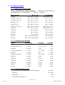


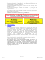
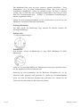

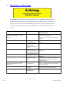
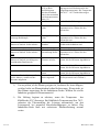
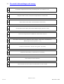

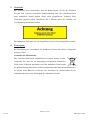
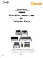
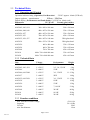


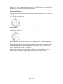


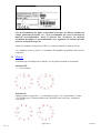


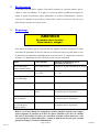

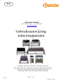


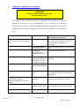


![infos sur les allergies aux matières pla[...]](http://vs1.manualzilla.com/store/data/006411260_1-7670f878c23d979b43cde6a0e0ebfb4e-150x150.png)