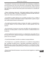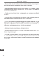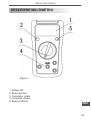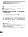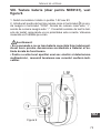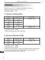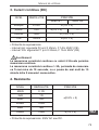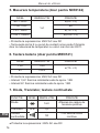
1
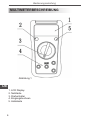
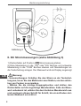
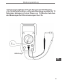
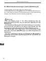
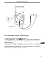
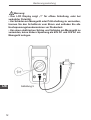
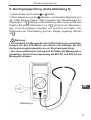
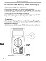
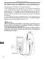
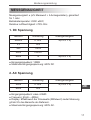
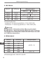
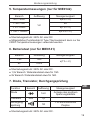
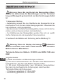
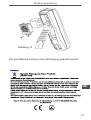
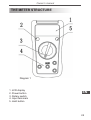
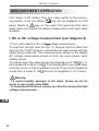
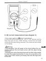
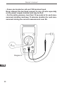
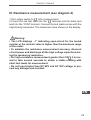
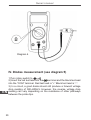
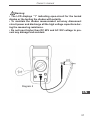
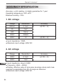
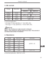
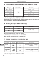
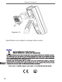
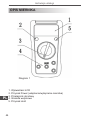
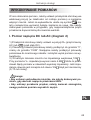
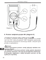
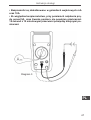
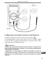
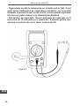
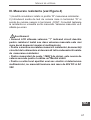
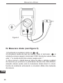
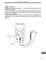
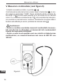
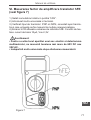
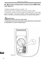
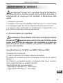
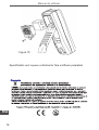
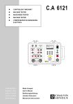
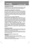
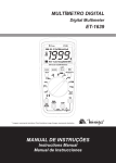
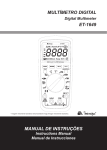
Palm size
digital
multimeter
MIE0141
MIE0142
Bedienungsanleitung DE
Owner’s manual EN
Instrukcja obsługi PL
Manual de utilizare RO
Bedienungsanleitung
EINLEITUNG
MIE0141/MIE0142 ist ein 3 ½ Anzeige Digital-Multimeter und folgenden Vorteilen: komplette Funktionen, neue Konfigurationen und
hohe Zuverlässigkeit. Es ist für die Messung von AC / DC-Spannung, DC Strom, Widerstand, Induktivität, Temperatur, Dioden Vorwärtsspannungsabfall, Transistor, hFE und Kontinuität, bestimmt.
Benutzen Sie den Multifunktionsstecker zur Messung von SMT.
Diese Bedienungsanleitung enthält Sicherheitshinweise und Hinweise im Zusammenhang mit diesem Messgerät, die Bedienungsanleitung vor Gebrauch sorgfältig lesen und befolgen Sie streng
alle Warnungen und Hinweise während der Bedienung.
Warnung: Um einen elektrischen Schlag oder Verletzungen zu vermeiden, lesen Sie die “Sicherheitshinweise” und “Regeln für den
sicheren Betrieb” sorgfältig, bevor Sie das Messgerät benutzen.
REGELN FÜR SICHERE BEDIENUNG
Warnung
Zur Vermeidung von Stromschlag oder Verletzungen und um mögliche Schäden am Messgerät oder an der getesteten Schaltung zu
vermeiden, sind folgende Regeln zu beachten:
● Bevor Sie das Messgerät benutzen, untersuchen Sie das Gehäuse. Verwenden Sie nicht das Messgerät, wenn es beschädigt
ist oder das Gehäuse (oder einen Teil davon) entfernt ist. Achten
Sie auf Risse oder fehlende Kunststoffteile. Achten Sie auf die Isolierung der Anschlüsse.
DE
● Kontrollieren Sie die Messleitungen auf beschädigte Isolierung
oder freiliegendes Metall. Überprüfen Sie die Messleitungen auf
Durchgang. Ersetzen Sie beschädigte Messleitungen mit identischen Modell-Nummer oder elektrischen Spezifikationen, bevor Sie das
Messgerät benutzen.
3
Bedienungsanleitung
● Überschreiten Sie nicht die auf dem Messgerät angegebene Nennspannung zwischen den Anschlüssen, bzw. zwischen den Anschlüssen und Erdung. Wenn der zu messende Wert unbekannt
ist, verwenden Sie die maximale Messposition und verringern den
Messbereich Schritt für Schritt, bis ein zufrieden stellender Messwert erreicht ist.
● Wenn die Messung abgeschlossen ist, trennen Sie die Verbindung zwischen den Messleitungen und der zu prüfenden Schaltung,
entfernen Sie die Messleitungen von den Eingangsklemmen des
Messgeräts und schalten das Messgerät aus.
● Der Drehschalter sollte in die richtige Position gebracht werden
und keine Bereichumstellung darf während der Messung durchgeführt werden, um eine Beschädigung des Messgerätes zu verhindern.
● Keine Messung durchführen, wenn das Gehäuse des Messgerätes oder das Batteriefach nicht geschlossen sind, um Stromschläge zu vermeiden.
● Keine höhere Spannung als 600V zwischen den Eingangsklemmen des Messgeräts und der Erdung anlegen, zu einem elektrischen Schlag und Schäden am Messgerät zu vermeiden.
DE
● Wenn das Messgerät mit einer effektiven Spannung über 60V
Gleichstrom oder 30V rms Wechselstrom arbeitet, ist besondere
Sorgfalt geboten, es besteht die Gefahr eines elektrischen Schlags.
● Verwenden Sie die richtigen Anschlüsse, Funktionen und Bereiche für die Messungen.
● Verwenden oder lagern Sie das Messgerät nicht in einer Umgebung mit hoher Temperatur, Feuchtigkeit, Explosionsgefahr, brennbaren Materialien und starkes Magnetfeld. Die Leistung des Messgeräts kann sich verschlechtern, nachdem aussetzen an Dämpfe.
4
Bedienungsanleitung
● Wenn Sie die Messspitzen verwenden, halten Sie Ihre Finger
hinter dem Fingerschutz.
● Trennen Sie den Schaltkreis vom Strom und entladen Sie alle
Hochspannungskondensatoren vor Widerstands-, Durchgangs- und
Diodentest.
● Tauschen Sie die Batterie so bald die Batterie-Anzeige erscheint.
Mit einer schwachen Batterie, kann das Messgerät falsche Messwerte anzeigen, die zu Stromschlag oder Verletzungen führen können.
● Bei der Wartung des Messgeräts, verwenden Sie nur das gleiche
Modell Nummer oder Ersatzteile mit identischen elektrischen Spezifikationen.
● Die interne Schaltung des Messgeräts darf nicht verändert werden,
um eine Beschädigung des Messgeräts und Unfälle zu vermeiden.
● Um die Oberfläche des Messgeräts reinigen verwenden Sie ein
weiches Tuch und ein mildes Reinigungsmittel. Verwenden Sie keine Scheuer- und Lösungsmittel, um die Oberfläche des Messgeräts
vor Korrosion, Beschädigungen und Unfälle zu schützen.
● Das Messgerät ist für den Innenbereich geeignet.
● Das Messgerät ausschalten, wenn es nicht in Gebrauch ist, und
entnehmen Sie die Batterie, wenn es für eine lange Zeit nicht benutzt wird.
DE
● Überprüfen Sie ständig die Batterie, da sie austreten kann, wenn
es für längere Zeit nicht benutzt wurde, ersetzen Sie die Batterie
so bald diese undicht wird. Eine undichte Batterie beschädigt das
Messgerät.
5
Bedienungsanleitung
MULTIMETERBESCHREIBUNG
Abbildung 1
DE
1. LCD Display
2. Netztaste
3. Drehschalter
4. Eingangsbuchsen
5. Haltetaste
6
Bedienungsanleitung
MESSVORGANG
Überprüfen Sie zuerst die 9V Batterie, danach stellen Sie den
Drehschalter auf den gewünschten Messvorgang. Bei schwacher
Batterie erscheint im Display
, Das Symbol
an der Eingangsbuchse weist Sie darauf hin, nicht die maximale Eingangsspannung oder Eingangsstrom zu überschreiten.
I. DC oder AC Spannungsmessungen (siehe Abbildung 2)
1) Drehschalter auf Position V~ oder V
Spannungsmessung stellen.
2) Rote Messleitung in die “V” Buchse und schwarze Messleitung in
die “COM” Buchse stecken und Messleitungen an die Testschaltung
anlegen. Der Messwert wird am Display angezeigt, Wechselspannung wird als Effektivwert (rms) angezeigt.
3) In jedem Eingangsbereich hat das Multimeter eine Eingangsimpedanz von 10M . V~ Eingangsimpedanz ist etwa 4.5M .
. Dieser Ladeeffekt kann einen Messfehler bei der Messung von
Schaltkreisen mit hoher Impedanz hervorrufen. Wenn die Schaltkreisimpedanz kleiner oder gleich mit 10k , ist, ist der Fehler vernachlässigbar (0,1% oder kleiner).
Warnung:
• Um eventuell Schäden an dem Messgerät zu vermeiden, bitte
nicht höhere Spannungen als 600V eingeben.
• Um einen elektrischen Schlag zu vermeiden, seien Sie bitte
vorsichtig bei der Hochspannungs-Messung.
DE
7
Bedienungsanleitung
Abbildung 2
II. DC Strommessungen (siehe Abbildung 3)
1) Drehschalter auf Position A
Strommessung stellen.
2) Rote Messleitung in die “mA” oder“10A” Buchse und schwarze
Messleitung in die “COM” Buchse stecken und Messleitungen an
die Testschaltung anlegen. Der Messwert wird am Display angezeigt
DE
Warnung:
• Voraussetzungen: Schalten Sie den Strom an der Testschaltung aus, bevor Sie das Multimeter anschließen, um das entstehen von Funken zu vermeiden.
• Wählen Sie die richtige Eingangsbuchse und stellen den
Drehschalter auf die zugehörige Messfunktion. Falls der Messwert unbekannt ist, wählen Sie den höchsten Messbereich aus
und verringern diesen Schritt für Schritt, bis ein zufrieden stellender Messwert erreicht ist.
8
Bedienungsanleitung
• Sicherungen befinden sich auf den mA und 10A Eingang.
• Als Sicherheitsfunktion, sollte jede Messdauer weniger als 10
Sekunden betragen mit einer Pause von 15 Minuten zwischen
den Messungen bei Strommessungen über 5A.
Abbildung 3
DE
9
Bedienungsanleitung
III. Widerstandsmessungen (siehe Abbildung 4)
1) Drehschalter auf Position “ ” Ohm-Messungen.
2) Rote Messleitung in die “ ” Buchse und schwarze Messleitung in
die “COM” Buchse stecken und Messleitungen an die Testschaltung
anlegen. Der Messwert wird am Display angezeigt.
Warnung:
• Das LCD Display zeigt „1” für offene Schaltung, oder der
Messwiderstand ist höher als der maximale Messbereich des
Multimeters.
• Um Schäden am Messgerät oder Prüfschaltung zu vermeiden,
trennen Sie den Schaltkreis vom Strom und entladen Sie alle
Hochspannungskondensatoren vor Widerstandsmessung.
• Für Messungen über 1M , dauert es normalerweise einige
Sekunden mit kurzen Messleitungen um stabile Ergebnisse zu
bekommen.
• Um einen elektrischen Schlag und Schäden am Messgerät zu
vermeiden, keine höhere Spannung als 60V DC und 30V AC am
Messgerät anlegen.
DE
10
Bedienungsanleitung
Abbildung 4
IV. Diodentest (siehe Abbildung 5)
1) Drehschalter auf Position
stellen.
2) Rote Messleitung in die
Buchse und schwarze Messleitung
in die “COM” Buchse stecken. Rote Messleitungen ist “+”schwarze
Messleitung ist “-.
3) In einer Testschaltung erzeugt eine gute Diode einen Spannungsabfall von 500 ~ 800mV. Jedoch kann der Umgekehrte
Spannungsabfall abhängig sein von dem Widerstand der anderen
Verbindungen zwischen den Messspitzen.
DE
11
Bedienungsanleitung
Warnung:
• Das LCD Display zeigt „1” für offene Schaltung, oder bei
verkehrter Polarität.
• Um Schäden am Messgerät oder Prüfschaltung zu vermeiden,
trennen Sie den Schaltkreis vom Strom und entladen Sie alle
Hochspannungskondensatoren vor Diodentest.
• Um einen elektrischen Schlag und Schäden am Messgerät zu
vermeiden, keine höhere Spannung als 60V DC und 30V AC am
Messgerät anlegen.
DE
12
Abbildung 5
Bedienungsanleitung
V. Durchgangsprüfung (siehe Abbildung 6)
1) Drehschalter auf Position
stellen.
Buchse und schwarze Messleitung in
2) Rote Messleitung in die
die “COM” Buchse stecken. Wenn zwischen den Messleitungen der
Widerstand >70 , beträgt, ist die Schaltung offen und es ertönt kein
Piepton. Bei einem Widerstand von 10 , zwischen den Messleitungen, ist ein Durchgang vorhanden und es ertönt ein Piepton. Der
Widerstand der Testschaltung wird am Display angezeigt (Einheit
ist ).
Warnung:
• Um Schäden am Messgerät oder Prüfschaltung zu vermeiden,
trennen Sie den Schaltkreis vom Strom und entladen Sie alle
Hochspannungskondensatoren vor Durchgangsprüfung.
• Um einen elektrischen Schlag und Schäden am Messgerät zu
vermeiden, keine höhere Spannung als 60V DC und 30V AC am
Messgerät anlegen.
DE
Abbildung 6
13
Bedienungsanleitung
VI. Transistor hFE Messung (siehe Abbildung 7)
1) Drehschalter auf Position “hFE” stellen.
2) Multifunktionsstecker in die Messbuchsen einstecken.
3) Überprüfen Sie den Transistor er ist entweder PNP oder NPN,
montiert oder SMT, und schließen Sie dann den zu messenden
Transistor an die entsprechenden Buchsen an
4) Im LCD Display wird der Referenzwert hFE angezeigt. Die Prüfungs-Voraussetzung: Basisstrom 10μA, Vce 2,3V.
Warnung:
• Um einen elektrischen Schlag und Schäden am Messgerät
zu vermeiden, keine höhere Spannung als 60V DC und 30V AC
am Messgerät anlegen.
• Nach beenden der Messung Multifunktionsstecker entfernen.
DE
Abbildung 7
14
Bedienungsanleitung
VII. Temperaturmessungen (nur für MIE0142), siehe Abbildung 8.
1) Drehschalter auf Position“0C”stellen.
2) Multifunktionsstecker in die Messbuchsen einstecken.
3) K—Type Punktkontakt-Messsonde kann nur für Temperaturmessungen unter 2300C verwendet werden, zur Messung von Temperaturen über 2300C muss eine separate Messsonde gekauft werden.
4) Im LCD Display wird “1” angezeigt wenn kein Kontakt mit der
Messsonde besteht. Bei Kurzschluss zwischen den Messbuchsen
wird Raumtemperatur angezeigt.
Warnung:
• Halten Sie die Punktkontakt-Messsonde rein um den Kontakteinfluss der Sonde zu verringern.
• Nach der Messung Messsonde entfernen und gut aufheben.
DE
Abbildung 8
15
Bedienungsanleitung
VIII. Batterietest (nur MIE0141), siehe Abbildung 9.
1)Drehschalter auf Position 1,5V oder 9V stellen.
Buchse und schwarze Messleitung
2) Rote Messleitung in die
in die “COM” Buchse stecken. Rote Messleitung ist “+”, schwarze
Messleitung ist “-”. Schließen Sie die Messleitungen an der zu testenden Batterie an, unter Beachtung der korrekten Polarität. Der angezeigte Wert ist die Spannung zwischen der Anode und Kathode
der Batterie.
3) 1,5V Einstellung Trockenzelle Batterietest ≤1.5V Widerstandslast
etwa für 15Ω; 9V Einstellung ist nur für nur für Trockenzellen Batterietest ≤15V Widerstandslast etwa für 1kΩ.
Warnung:
• Es wird Empfohlen die Batterie nicht lange angeschlossen zu
lassen. Dieses verhindert ein vorzeitiges entladen der Batterie
und verlängert ihre Funktionsdauer.
• Um einen elektrischen Schlag und Schäden am Messgerät zu
vermeiden, keine höhere Spannung oder Strom als angegeben
am Messgerät anlegen.
DE
Abbildung 9
16
Bedienungsanleitung
MESSGENAUIGKEIT
Messgenauigkeit: ± (a% Messwert + b Anzeigestellen), garantiert
für 1 Jahr.
Betriebstemperatur: 230C ±50C;
Relative Luftfeuchtigkeit: ≤75% R.H.
1. DC Spannung
Bereich
Auflösung
Messgenauigkeit
200mV
0.1mV
±(0.5% + 2)
2V
1mV
20V
10mV
200V
100mV
600V
1V
±(0.8% + 2)
● Eingangsimpedanz: 10MΩ
● Maximale Eingangsspannung: 600V DC
2. AC Spannung
Bereich
Auflösung
Messgenauigkeit
200V
0.1mV
±(1.2% + 3)
600V
1mV
DE
● Eingangsimpedanz: etwa 4.5MΩ
● Frequenz: 45Hz ~ 400Hz
● Display: Effektivwert der Sinuswelle (Mittelwert) Jeder Messung
gilt ab 5% des Bereichs als Referenz.
● Maximale Eingangsspannung: 600V AC.
17
Bedienungsanleitung
3. DC Strom
Bereich
Auflösung
2000μA
0.1mV
Messgenauigkeit
MIE0141
MIE0142
±(1% + 2)
20mA
1mV
200mA
10mV
±(1% + 2)
±(1.2% + 2)
---
10A
100mV
±(2% + 5)
● Überladungsschutz:
- mA Bereich: F2 Sicherung φ6x25mm, F 1A H 250V (CE)
- 10A Bereich: F1 Sicherung φ6x25mm, F 10A H 250V (CE)
Warnung:
Bei Messstrom ≤5A kontinuierliche Messung ist erlaubt.
Bei Messstrom >5A kontinuierliche Messung ist für die Dauer
von weniger als 10 Sekunden erlaubt mit einer Pause von mehr
als 15 Minuten dazwischen.
4. Widerstand
DE
Bereich
Auflösung
200Ω
0.1Ω
2kΩ
1Ω
20kΩ
10Ω
200kΩ
100Ω
2MΩ
1kΩ
20MΩ
10kΩ
● Überladungsschutz: 250V AC oder DC
18
Messgenauigkeit
±(0.8% + 5)
±(1% + 5)
Bedienungsanleitung
5. Temperaturmessungen (nur für MIE0142)
Bereich
Auflösung
Messgenauigkeit
-40 ~ -20 C
±(8% + 5)
0
> -20 ~ 00C
±4
10C
> 0 ~ 100 C
0
±(1% + 3)
> 100 ~ 10000C
±(2.5% + 2)
● Überladungsschutz: 250V AC oder DC
● Mitgeliefertes Punktkontakt K Type Thermoelement kann nur bis
2300C Temperaturmessungen verwendet werden.
6. Batterietest (nur für MIE0141)
Bereich
Auflösung
1.5V
1mV
9V
10mV
Messgenauigkeit
±(1% + 2)
● Überladungsschutz: 250V AC oder DC.
● 1,5V Bereich: Widerstandslast etwa für 15Ω.
● 9V Bereich: Widerstandslast etwa für 1kΩ.
7. Diode, Transistor, Durchgangsprüfung
Funktion
Bereich
Diode
Transistor
Durchgangsprüfung
hFE
Auflösung
Messgenauigkeit
1mV
Anzeige des positiven
Spannungsabfalls
DE
1β
1Ω
<1Ω kontinuierlicher
Piepton
● Überladungsschutz: 250V AC oder DC.
19
Bedienungsanleitung
WARTUNG UND SERVICE
Warnung: Bevor Sie den Deckel des Messgerätes öffnen,
stellen Sie sicher dass die Messleitungen von der Testschaltung und Messgerät getrennt sind und das Gerät ausgeschaltet
ist.
1. Allgemeine Wartung
• Regelmäßig reinigen Sie die Oberfläche des Messgeräts mit einem weichen Tuch und ein mildes Reinigungsmittel. Verwenden Sie
keine Scheuer- und Lösungsmittel.
• Bei abnormalen Verhalten des Messgerätes, dieses nicht mehr benutzen und zum Servicezentrum zurückschicken.
• Zur Kalibrierung des Messgerätes wenden Sie sich an qualifiziertes Fachpersonal oder speziellem Servicezentrum.
2. Austausch der Batterie und Sicherung, siehe Abbildung 10.
Warnung: Wenn im Display die Anzeige
schwacher
Batterie erscheint, muss diese ersetzt werden. Eine schwache
Batterie führt zu Messfehlern.
Technische Daten der Batterie: 9V BF22 oder NEDA 1604 oder
006P.
DE
20
Vorgehensweise:
(1) Gerät ausschalten und Messleitungen entfernen.
(2) Mit einem Schraubenzieher die Schraube des Batteriedeckels
herausnehmen. Nun kann die Batterie ersetzt werden.
(3) Mit einem Schraubenzieher zwei Schrauben herausnehmen.
Nun kann die durchgebrannte Sicherung(en) ersetzt werden.
Technische Daten der Sicherungen:
- F1 Sicherung φ6x25mm, F 10A H 250V
- F2 Sicherung φ6x25mm, F 1A H 250V
Bedienungsanleitung
Abbildung 10
Die Spezifikationen können ohne Ankündigung geändert werden.
DE
21
Owner’s manual
OVERVIEW
MIE0141/MIE0142 multimeter is a hand-held 3 1/2 digital display
digital multimeters with advanced design, multiple entire functions,
novel figurations and reliable performance. This meter is fully capable to measure voltage both AC and DC, DC current, resistance,
inductance, temperature and forward voltage drop of diode, transistor, hFE and continuity test etc. Please use multi-purpose socket to
measure SMT as well. This operating manual covers information on
safety and cautions to fulfill CE mark standard. Please read the relevant information carefully and observe all the warnings and notes
strictly.
Warning: To avoid electric shock or personal injury, read the “Safety
information” and „Rules for Safe Operation” carefully before using
the meter.
RULES FOR SAFE OPERATION
Warning
To avoid possible electric shock or personal injury, and to avoid possible damage to the Meter or to the equipment under test, adhere to
the following rules:
EN
● Before using the Meter inspect the case. Do not use the Meter if
it is damaged or the case (or part of the case) is removed. Look for
cracks or missing plastic. Pay attention to the insulation around the
connectors.
● Inspect the test leads for damaged insulation or exposed metal.
Check the test leads for continuity. Replace damaged test leads with
identical model number or electrical specifications before using the
Meter.
22
Owner’s manual
● Do not apply more than the rated voltage, as marked on the Meter.
● When measurement has been completed, disconnect the connection between the test leads and the circuit under test and turn the
Meter power off.
● The rotary switch should be placed in the right position and no any
changeover of range shall be made during measurement is conducted to prevent damage of the Meter.
● Do not carry out the measurement when the Meter’s back case
and battery compartment are not closed to avoid electric shock.
● When the Meter working at an effective voltage over 60V in DC
or 30V rms in AC, special care should be taken for there is danger
of electric shock.
● Use the proper terminals, function, and range for your measurements.
● Do not use or store the Meter in an environment of high temperature, humidity, explosive, inflammable and strong magnetic field.
The performance of the Meter may deteriorate after dampened.
● When using the test leads, keep your fingers behind the finger
guards.
● Disconnect circuit power and discharge all high-voltage capacitors
before testing resistance, continuity and diode.
● Replace the battery as soon as the battery indicator appears. With
a low battery, the Meter might produce false readings that can lead
to electric shock and personal injury.
EN
● When servicing the Meter, use only the same model number or
identical electrical specifications replacement parts.
23
Owner’s manual
● The internal circuit of the Meter shall not be altered at will to avoid
damage of the Meter and any accident.
● Soft cloth and mild detergent should be used to clean the surface
of the Meter when servicing. No abrasive and solvent should be
used to prevent the surface of the Meter from corrosion, damage
and accident.
● The Meter is suitable for indoor use.
● Turn the Meter off when it is not in use and take out the battery
when not using for a long time.
● Constantly check the battery as it may leak when it has been using for some time, replace the battery as soon as leaking appears. A
leaking battery will damage the Meter.
EN
24
Owner’s manual
THE METER STRUCTURE
Diagram 1
1. LCD display
2. Power button
3. Rotary switch
4. Input terminals
5. Hold button
EN
25
Owner’s manual
MEASUREMENT OPERATION
First check on 9V battery, then turn rotary switch to the measursign will be displayed on LCD
ing position. lf the low battery,
panel. Nearly to
sign on the meter front panel terminal input
which alarm not exceed the testing voltage and current input value
limitation.
I. DC or AC voltage measurement (see diagram 2)
1) Turn rotary switch to V~ or V
voltage measurement.
2) Insert the red test lead into the “V” terminal and the black test
lead into the “COM” terminal, connect the lest leads across with the
object being measured. The measured value shows on the display
AC voltage measurement shows on true root mean square value
stability period.
3) In each range, the meter has an input impedance of 10M . V~ input impedance is about 4.5M . This loading effect can cause measurement errors in high impedance circuits. If the circuit impedance
is less than or equal to 10k , the error is negligible (0.1% or less).
Warning:
• To avoid possibly damages to the meter, please do not attempt to input higher than 600V.
• To avoid electrical shock, please pay attention during the high
voltage measurement.
EN
26
Owner’s manual
Diagram 2
II. DC current measurement (see diagram 3)
1) Turn rotary switch to A
current measurement.
2) Insert the red test lead into the „ mA” or ”10A” terminal, and the
black test lead into the „COM” terminal, Connect the test leads
across with the object being measured. The measured value shows
on the display.
EN
Warning:
• Pre-requisites: Turn off power to the circuit before the connection between the test leads across with the object being
measured.
• Selecting the correct terminal input and turn the rotary switch
to select the measuring function. In case of no any idea on the
value input of the current, just simply test from the high value
to low one.
27
Owner’s manual
• Fuses are located on mA and 10A terminal input.
Never attempt the test lead connect to any circuits especially
on the power supply terminal and may be hurt.
• For the safety purpose, less than 10 seconds is for each measurement duration and keep 15 minutes duration for next measurement during the current measurement over 5A.
Diagram 3
EN
28
Owner’s manual
III. Resistance measurement (see diagram 4)
1)Turn rotary switch to “ ” ohm measurement.
2) Insert the red test lead into the “ ” terminal and the black test
lead into the “COM” terminal. Connect the test leads across with the
object being measured. The measured value shows on the display.
Warning:
• The LCD displays „1” indicating open-circuit for the tested
resistor or the resistor value is higher than the maximum range
of the meter.
• To maintain the resistance measurement accuracy, discount
circuit power and discharge all the high voltage capacitors during the measuring resistance.
• For high-resistance measurement greater than 1M , it is normal to take several seconds to obtain a stable reading with
short test leads for measurement.
• Do not input higher than DC 60V and AC 30V voltage to prevent any damage and accident.
EN
29
Owner’s manual
Diagram 4
IV. Diodes measurement (see diagram 5)
EN
30
1)Turn rotary switch to
.
2) Insert the red test lead into the
terminal and the black test lead
into the “COM” terminal. Red test lead is “+” Black test lead is “-”.
3) In a circuit, a good diode should still produce a forward voltage
drop reading of 500~800mV. However, the reverse voltage drop
reading can vary depending on the resistance of other pathways
between the probe tips.
Owner’s manual
Warning:
• The LCD displays “1” indicating open-circuit for the tested
diodes or the testing the diodes with polarity.
• To maintain the diodes measurement accuracy disconnect
circuit power and discharge all the high voltage capacitors during the measuring resistance.
• Do not input higher than DC 60V and AC 30V voltage to prevent any damage and accident.
Diagram 5
EN
31
Owner’s manual
V. Continuity measurement (see diagram 6)
1)Turn rotary switch to
.
terminal and the black test lead
2) Insert the red test lead into the
into the “COM” terminal. If between both terminals show resistance
>70 , it is a short-circuit,no buzzer, but if between both terminals
show resistances 10 , it is a good connection with continually buzzer. Resistance value on tested circuit display on LCD (Unit is ).
Warning:
• To maintain the diodes measurement accuracy disconnect
circuit power and discharge all the high voltage capacitors during the measuring resistance.
• Do not input higher than DC 60V and AC 30V voltage to prevent any damage and accident.
EN
Diagram 6
32
Owner’s manual
VI. Transistor hFE measurement (see diagram 7)
1)Turn rotary switch to “hFE”.
2) Put the muItiple purpose socket into the terminal.
3) Check the transistor is either PNP or NPN, assembles or SMT,
then connect the transistor to be measured to the corresponding
jacks.
4) LCD display hFE reference value. The testing requirement: basic
current 10μA,Vce for 2.3V.
Warning:
• To avoid damages to the Meter or to the devices under test, do
not input any current over 60V DC or 30V AC.
• Take off the multi-purpose socket after the measurement.
EN
Diagram 7
33
Owner’s manual
VII. Temperature measurement (for MIE0142 onIy),
see diagram 8.
1) Turn rotary switch to “0C”.
2) Put the multiple purpose socket into the correct terminal.
3) K—Type point contact temperature probe can only be used in the
measurement below 2300C, if you want to measure over 2300C, you
need to separately buy another temperature probe.
4) The LCD displays “1” indicating point contact temperature probe
which take off. When short circuit between, terminal and COM terminal, the meter show the value of room temperature.
Warning:
• Maintain clean the point contact temperature probe and do
not let the probe contact point to have any serious influence.
• Take off and well keep the point contact temperature after the
measurement.
EN
Diagram 8
34
Owner’s manual
VIII. Battery test (MIE0141 onIy), see diagram 9.
1)Turn rotary switch to 1.5V or 9V.
terminal and the black test
2) Insert the red test lead into the
lead into the “COM” terminal. Red test lead is “+”, black test lead is
“-”. Connect the test leads across with the battery being measured
ensuring the polarity is correct. The measured value shows on the
display, which is the voltage between the cathode and anode of the
battery.
3) 1.5V usage ≤1.5V dry cell battery test, resistance load is approximately for 15Ω; 9V is only suitable for ≤15V dry cell battery test,
resistance load is approximately for 1kΩ.
Warning:
• Refuse to keep a long time connection battery in the measuring process, it avoids to loss the battery energy, to reduce
battery’s life.
• Refuses to use in over the specification of the battery or the
current test, in order to avoid damages the measuring appliance and endangers the personal safety!
EN
Diagram 9
35
Owner’s manual
ACCURACY SPECIFICATION
Accuracy: ± (a% reading + b digits) guarantee for 1 year
Operating temperature: 230C ±50C
Relative humidity: <75%
1. DC voltage
Range
Resolution
Accuracy
200mV
0.1mV
±(0.5% + 2)
2V
1mV
20V
10mV
200V
100mV
600V
1V
±(0.8% + 2)
● Input impedance: 10MΩ
● Maximum input voltage: 600V DC
2. AC voltage
EN
Range
Resolution
Accuracy
200V
0.1mV
±(1.2% + 3)
600V
1mV
● Input impedance: about 4.5MΩ
● Frequency: 45Hz ~ 400Hz
● Display: effective value of sine wave (average value) each measurement is applicable from 5% of range as reference.
● Maximum input voltage: 600V AC.
36
Owner’s manual
3. DC current
Range
Resolution
2000μA
0.1mV
Accuracy
MIE0141
MIE0142
±(1% + 2)
20mA
1mV
200mA
10mV
±(1% + 2)
±(1.2% + 2)
---
10A
100mV
±(2% + 5)
● Overload protection:
- mA range: F2 fuse φ6x25mm, F 1A H 250V (CE)
- 10A range: F1 fuse φ6x25mm, F 10A H 250V (CE)
Warning:
When ≤5A continuous measurement is allowed.
When > 5A continuous measurement less than 10 seconds at
an interval more than 15 minutes.
4. Resistance
Range
Resolution
200Ω
0.1Ω
2kΩ
1Ω
20kΩ
10Ω
200kΩ
100Ω
2MΩ
1kΩ
20MΩ
10kΩ
Accuracy
±(0.8% + 5)
EN
±(1% + 5)
● Overload protection: 250V AC or DC
37
Owner’s manual
5. Temperature measurement (for MIE0142 only)
Range
Resolution
Accuracy
-40 ~ -20 C
±(8% + 5)
0
> -20 ~ 00C
±4
10C
> 0 ~ 100 C
0
±(1% + 3)
> 100 ~ 10000C
±(2.5% + 2)
● Overload protection: 250V AC or DC.
● Enclosed point contact K type thermocouple can only be used on
less than 2300C temperature measurement.
6. Battery test (for MIE0141 only)
Range
Resolution
1.5V
1mV
9V
10mV
Accuracy
±(1% + 2)
● Overload protection: 250V AC or DC.
● 1.5V range: resistance load is about 15Ω.
● 9V range: resistance load is about 1kΩ.
7. Diode, transistor, continuity test
Function
EN
Range
Diode
Transistor
Continuity
test
hFE
Resolution
Accuracy
1mV
Display positive voltage
decline
1β
1Ω
● Overload protection: 250V AC or DC.
38
<1Ω buzzer beep continuously
Owner’s manual
MAINTENANCE AND SERVICE
Warning: Make sure the test leads take off the terminal and
the circuit as well as power off the meter if want to open the
meter cover.
1. General service and maintenance
• Periodically wipe the case with a damp cloth and mild detergent.
Do not use abrasives or solvents.
• Any abnormal on the meter, stop use the meter and return to service center.
• When need to have calibration on the meter, please allow certified
engineer or specific service center for the service maintenance.
2. Replacing the battery and fuse, see diagram 9.
Warning: LCD display
sign indicating battery will be
run out and need to replace a new battery, if fail to do that. It
causes the variance of the measuring result.
Battery specification: 9V BF22 or NEDA 1604 or 006P
Operating steps:
(1) Turn the power in “off“ situation, then remove the test lead out
of the meter.
(2) Use screwdriver to take off the screw on the battery cover. Then
you can take off old battery for replacing.
(3) User screwdriver to take off two pieces of screws, then you can
replacing the burned fuse(s) as replacement. Fuse specification:
- F1 fuse φ6x25mm, F 10A H 250V
- F2 fuse φ6x25mm, F 1A H 250V
EN
39
Owner’s manual
Diagram 10
Specifications are subject to change without notice.
EN
40
Instrukcja obsługi
WSTĘP
MIE0141/MIE0142 z cyfrowym wyświetlaczem 3 1/2, charakteryzuje się dużą ilością funkcji, prostotą i wygodą użytkowania oraz niezawodnością działania. Miernik przeznaczony jest do pomiaru napięcia prądu stałego i zmiennego, natężenia prądu stałego, rezystancji, diod, ciągłości obwodu, hFE, temperatury (MIE0142), baterii
(MIE0141) itp. Przed pierwszym użyciem miernika, należy dokładnie przeczytać instrukcję obsługi i stosować się do wszystkich zaleceń i informacji w niej zawartych. Instrukcję należy zachować w celu
późniejszego wykorzystania.
Uwaga: Aby uniknąć porażenia prądem elektrycznym, należy dokładnie i ze zrozumieniem przeczytać rozdział „Zasady bezpieczeństwa” oraz stosować się do zaleceń w nim zawartych.
ZASADY BEZPIECZEŃSTWA
Uwaga
Aby uniknąć porażenia prądem elektrycznym lub innych uszkodzeń
ciała, należy uważnie przeczytać i przestrzegać poniższych zasad:
● Przed użyciem miernika należy sprawdzić obudową, czy nie posiada uszkodzeń, jest zamknięta i skręcona wkrętami.
● Należy sprawdzić przewody pomiarowe, czy nie mają uszkodzeń
izolacji.
● Nigdy nie wolno używać miernika, jeżeli napięcie płynące w mierzonym obwodzie jest wyższe niż maksymalne napięcie dla danego modelu miernika.
PL
41
Instrukcja obsługi
● Po zakończonym pomiarze należy odłączyć przewody pomiarowe od mierzonego obiektu, odpiąć je od miernika i wyłączyć miernik.
● Obrotowy przełącznik powinien być ustawiony we właściwej pozycji przed dokonaniem pomiaru (nie należy go przekręcać w trakcie pomiaru).
● Nie należy używać miernika, jeżeli tylna obudowa i pokrywa baterii nie jest całkowicie zamknięta.
● Należy zachować szczególną ostrożność przy pomiarach, gdzie
napięcie ma wartość powyżej 60V DC lub 30V AC.
● Należy dostosować położenie przełącznika obrotowego oraz sposób pomiaru do danego rodzaju pomiaru.
● Nie należy używać i przechowywać miernika w miejscach o dużej
wilgotności powietrza, wysokiej temperaturze lub silnym polu elektromagnetycznym.
● Używając przewodów pomiarowych należy pamiętać, aby palce
znajdowały się za osłoną ochronną.
● Należy wyłączyć zasilanie z mierzonego obwodu i rozładować wysokonapięciowe kondensatory przed pomiarem natężenia prądu,
rezystancji lub przed sprawdzaniem diod.
● Baterię należy wymienić na nową niezwłocznie po pojawieniu się
symbolu niskiego stanu naładowania baterii.
● Jeżeli podczas serwisowania miernika zachodzi konieczność wymiany elementu, to należy go wymienić na identyczny z oryginałem.
PL ● Nie wolno dokonywać żadnych zmian wewnątrz miernika.
● Do czyszczenia obudowy miernika należy używać wyłącznie
miękkiej ściereczki i delikatnego detergentu (nie należy stosować
silnych środków czyszczących).
42
Instrukcja obsługi
● Miernik przeznaczony jest do użytku wewnątrz pomieszczeń.
● Po zakończeniu pomiarów, należy wyłączyć miernik. Jeżeli miernik nie będzie używany przez dłuższy okres czasu, należy wyjąć baterię zasilającą.
● Należy okresowo sprawdzać stan zainstalowanej baterii. Cieknąca bateria może spowodować uszkodzenie miernika.
PL
43
Instrukcja obsługi
OPIS MIERNIKA
Diagram 1
PL
44
1. Wyświetlacz LCD
2. Przycisk Power (włączenie/wyłączenie miernika)
3. Przełącznik obrotowy
4. Gniazda wejściowe
5. Przycisk Hold
Instrukcja obsługi
WYKONYWANIE POMIARÓW
W celu dokonania pomiaru, należy ustawić przełącznik obrotowy we
właściwej pozycji (w zależności od rodzaju pomiaru) a następnie
, nawłączyć miernik. Jeżeli na wyświetlaczu ukaże się symbol
leży niezwłocznie wymienić baterię zasilania na nową. Nie należy
dokonywać pomiarów w przypadku, gdy napięcie/natężenie prądu
przekracza dopuszczalną dla miernika wartość.
I. Pomiar napięcia DC lub AC (diagram 2)
1) Przełącznik obrotowy należy ustawić w pozycji V~ (prąd zmienny
AC) lub V
(prąd stały DC).
2) Czerwony przewód pomiarowy należy podłączyć do gniazda “V”,
czarny do gniazda “COM”. Następnie należy podłączyć przewody
pomiarowe do mierzonego obiektu i odczytać wynik pomiaru na wyświetlaczu.
3) W każdym zakresie miernik ma impedancję wejściową 10M .
Przy pomiarze V~ impedancja wynosi około 4.5M . Może to powodować błędy pomiaru w obwodach wysokiej impedancji. Jeśli impedancja obwodu jest mniejsza lub równa 10k , błąd jest nieznaczny
(0,1% lub mniej).
Uwaga:
• Aby uniknąć uszkodzenia miernika, nie należy dokonywać pomiaru, gdy wartość napięcia przekracza 600V.
• Aby uniknąć porażenia prądem, należy zwracać szczególną
uwagę podczas pomiaru wysokich napięć.
PL
45
Instrukcja obsługi
Diagram 2
II. Pomiar natężenia prądu DC (diagram 3)
1) Przełącznik obrotowy należy ustawić w pozycji A
.
2) Czerwony przewód pomiarowy należy podłączyć do gniazda
„mA” lub „10A”, czarny do gniazda “COM”. Następnie należy podłączyć przewody pomiarowe do mierzonego obiektu i odczytać wynik
pomiaru na wyświetlaczu.
PL
Uwaga:
• Przed rozpoczęciem pomiaru należy wyłączyć zasilanie mierzonego obwodu.
• W zależności o mierzonej wartości należy wybrać odpowiednie gniazdo wejściowe oraz pozycję przełącznika obrotowego.
W przypadku wątpliwości, należy sprawdzić wartości od najwyższej do najniższej.
46
Instrukcja obsługi
• Bezpieczniki są zlokalizowane w gniazdach wejściowych mA
oraz 10A.
• Ze względów bezpieczeństwa, przy pomiarach natężenia prądu ponad 5A, czas trwania pomiaru nie powinien przekraczać
10 sekund z 15 minutowymi przerwami pomiędzy kolejnymi pomiarami.
Diagram 3
PL
47
Instrukcja obsługi
III. Pomiar rezystancji (diagram 4)
1) Przełącznik obrotowy należy ustawić w pozycji “ ”.
2) Czerwony przewód pomiarowy należy podłączyć do gniazda
„ ”, czarny do gniazda “COM”. Następnie należy podłączyć przewody pomiarowe do mierzonego obiektu i odczytać wynik pomiaru na wyświetlaczu.
Uwaga:
• Wartość „1” na wyświetlaczu oznacza obwód otwarty lub wartość przekraczająca zakres miernika.
• Aby zachować dokładność pomiaru, przed jego rozpoczęciem
należy odłączyć urządzenie od źródła zasilania oraz rozładować wysokonapięciowe kondensatory.
• W przypadku pomiaru rezystancji o wartości przekraczającej
1M , może zajść konieczność odczekania kilku sekund w celu
otrzymania stabilnego odczytu.
• Nie należy dokonywać pomiarów jeżeli napięcie przekracza
60V DC lub 30V AC.
PL
48
Instrukcja obsługi
Diagram 4
IV. Test diod (diagram 5)
1) Przełącznik obrotowy należy ustawić w pozycji
.
2) Czerwony przewód pomiarowy należy podłączyć do gniazda
czarny do gniazda “COM”. Czerwony przewód to “+”, czarny “-”.
3) W obwodzie, dobra dioda powinna generować wsteczne napięcie
w zakresie 500 ~ 800mV. Wartość ta może się jednak zmieniać w
zależności od oporu innych ścieżek między końcówkami próbnika.
PL
49
Instrukcja obsługi
Uwaga:
• Wartość „1” na wyświetlaczu oznacza obwód otwarty lub testowanie diod z polaryzacją.
• Aby zachować dokładność pomiaru, przed jego rozpoczęciem
należy odłączyć urządzenie od źródła zasilania oraz rozładować wysokonapięciowe kondensatory.
• Nie należy dokonywać pomiarów jeżeli napięcie przekracza
60V DC lub 30V AC.
Diagram 5
PL
50
Instrukcja obsługi
V. Test ciągłości obwodu (diagram 6)
1) Przełącznik obrotowy należy ustawić w pozycji
.
2) Czerwony przewód pomiarowy należy podłączyć do gniazda
, czarny do gniazda “COM”. Wartość rezystancji powyżej 70 i brak
sygnału dźwiękowego oznacza zwarcie, wartość rezystancji poniżej
10 i ciągły sygnał dźwiękowy oznacza prawidłowe połączenie. Wyświetlana na ekranie wartość wyrażana jest w .
Uwaga:
• Aby zachować dokładność pomiaru, przed jego rozpoczęciem
należy odłączyć urządzenie od źródła zasilania oraz rozładować wysokonapięciowe kondensatory.
• Nie należy dokonywać pomiarów jeżeli napięcie przekracza
60V DC lub 30V AC.
PL
Diagram 6
51
Instrukcja obsługi
VI. Pomiar hFE tranzystora (diagram 7)
1) Przełącznik obrotowy należy ustawić w pozycji “hFE”.
2) Do gniazd wejściowych miernika należy podłączyć przejściówkę
pomiarową.
3) W zależności od rodzaju, tranzystor należy podłaczyć do
przejściówki pomiarowej w odpowiedni sposób.
4) Na ekranie wyświetlana jest wartość referencyjna hFE.
Wymagane 10μA,Vce dla 2.3V.
Uwaga:
• Nie należy dokonywać pomiarów jeżeli napięcie przekracza
60V DC lub 30V AC.
PL
Diagram 7
52
Instrukcja obsługi
VII. Pomiar temperatury (MIE0142), diagram 8.
1) Przełącznik obrotowy należy ustawić w pozycji “0C”.
2) Do gniazd wejściowych miernika należy podłączyć przejściówkę pomiarową do której następnie należy podłączyć czujnik pomiaru temperatury.
3) Znajdujący się w zestawie czujnik służy do pomiaru temperatury
nie przekraczającej 2300C. Do pomiaru wyższych temperatur należy dokupić dodatkowy czujnik.
4) Wartość “1” na wyświetlaczu, oznacza odłączenie punktu pomiarowego od czujnika.
Uwaga:
• Należy zapobiegać wszelkim zabrudzeniom końcówki czujnika temperatury.
PL
Diagram 8
53
Instrukcja obsługi
VIII. Test baterii (MIE0141), diagram 9.
1) Przełącznik obrotowy należy ustawić w pozycji 1.5V lub 9V.
2) Czerwony przewód pomiarowy należy podłączyć do gniazda
czarny do gniazda “COM”. Czerwony przewód to “+”, czarny “-”. Następnie należy podłączyć przewody pomiarowe do mierzonej baterii
i odczytać wynik pomiaru na wyświetlaczu.
Uwaga:
• Należy unikać długotrwałych pomiarów baterii, powoduje to
utratę energii akumulatora i zmniejsza jego żywotność.
• Nie należy mierzyć innych typów baterii niż określone w specyfikacji.
PL
Diagram 9
54
Instrukcja obsługi
DOKŁADNOŚĆ POMIARÓW
Dokładność: ±(a% odczytu + b cyfr), gwarantowana przez 1 rok.
Temperatura pracy: 230C ±50C
Względna wilgotność: ≤75%R.H
1. Pomiar napięcia DC
Zakres
Rozdzielczość
Dokładność
200mV
0.1mV
±(0.5% + 2)
2V
1mV
20V
10mV
200V
100mV
600V
1V
±(0.8% + 2)
● Impedancja wejściowa: 10MΩ
● Maksymalne napięcie wejściowe: 600V DC
2. Pomiar napięcia AC
Zakres
Rozdzielczość
Dokładność
200V
0.1mV
±(1.2% + 3)
600V
1mV
● Impedancja wejściowa: około 4.5MΩ
● Częstotliwość: 45Hz ~ 400Hz
● Maksymalne napięcie wejściowe: 600V AC.
PL
55
Instrukcja obsługi
3. Pomiar natężenia prądu DC
Zakres
Rozdzielczość
Dokładność
MIE0141
2000μA
0.1mV
20mA
1mV
MIE0142
±(1% + 2)
±(1% + 2)
---
200mA
10mV
±(1.2% + 2)
10A
100mV
±(2% + 5)
● Zabezpieczenie przed przeciążeniem:
- zakres mA: bezpiecznik F2 φ6x25mm, F 1A H 250V (CE)
- zakres 10A: bezpiecznik F1 φ6x25mm, F 10A H 250V (CE)
Uwaga:
W przypadku pomiaru natężenia prądu o wartości ≤5A dozwolony jest pomiar ciągły.
W przypadku pomiaru natężenia prądu o wartości > 5A czas
trwania pomiaru nie powinien przekraczać 10 sekund z 15 minutowymi przerwami pomiędzy kolejnymi pomiarami.
4. Pomiar rezystancji
PL
Zakres
Rozdzielczość
200Ω
0.1Ω
2kΩ
1Ω
20kΩ
10Ω
200kΩ
100Ω
2MΩ
1kΩ
20MΩ
10kΩ
Dokładność
±(0.8% + 5)
±(1% + 5)
● Zabezpieczenie przed przeciążeniem: 250V AC / DC
56
Instrukcja obsługi
5. Pomiar temperatury (MIE0142)
Zakres
Rozdzielczość
-40 ~ -20 C
Dokładność
±(8% + 5)
0
> -20 ~ 00C
±4
10C
> 0 ~ 100 C
0
±(1% + 3)
> 100 ~ 10000C
±(2.5% + 2)
● Zabezpieczenie przed przeciążeniem: 250V AC / DC.
● Znajdujący się w zestawie czujnik służy do pomiaru temperatury
nie przekraczającej 2300C.
6. Test baterii (MIE0141)
Zakres
Rozdzielczość
1.5V
1mV
9V
10mV
Dokładność
±(1% + 2)
● Zabezpieczenie przed przeciążeniem: 250V AC / DC.
● 1.5V: rezystancja obciążenia wynosi około 15Ω.
● 9V: rezystancja obciążenia wynosi około 1kΩ.
7. Dioda, tranzystor, ciągłość obwodu
Funkcja
Zakres
Dioda
Tranzystor
Ciągłość
obwodu
hFE
Rozdzielczość
Dokładność
1mV
Wyświetla spadek napięcia
1β
1Ω
PL
<1Ω ciągły sygnał dźwiękowy
● Zabezpieczenie przed przeciążeniem: 250V AC / DC.
57
Instrukcja obsługi
KONSERWACJA
Uwaga: Przed zdjęciem pokrywy miernika, należy odłączyć
przewody pomiarowe i wyłączyć miernik.
1. Ogólny serwis i konserwacja.
• Wszelkie zabrudzenia należy usuwać za pomocą wilgotnej ściereczki z delikatnym detergentem (nie należy używać silnych środków czyszczących).
• W przypadku nieprawidłowej pracy miernika lub jego uszkodzenia
należy skontaktować się z serwisem urządzenia. Nie należy próbować samodzielnie naprawiać miernika.
• Jeżeli zachodzi konieczność kalibracji miernika, należy skontaktować się z serwisem.
2. Wymiana baterii i bezpiecznika, diagram 9.
Uwaga: Baterię należy wymienić na nową niezwłocznie po
pojawieniu się symbolu “
” na wyświetlaczu.
Rodzaj baterii: 9V BF22
PL
Aby wymienić baterię/bezpiecznik należy:
(1) Wyłączyć urządzenie i odpiąć przewody pomiarowe.
(2) Zdjąć pokrywę baterii, odkręcając wcześniej śrubę zabezpieczającą a następnie wymienić baterię na nową.
(3) Odkręcić dwie śruby zabezpieczające bezpieczniki i wymienić
spalony bezpiecznik na nowy. Specyfikacja bezpieczników:
- bezpiecznik F1 φ6x25mm, F 10A H 250V
- bezpiecznik F2 φ6x25mm, F 1A H 250V
58
Instrukcja obsługi
Diagram 10
Specyfikacja urządzenia może ulec zmianie bez powiadomienia.
PL
59
Manual de utilizare
INTRODUCERE
MIE0141/MIE0142 este un multimetru digital portabil, cu afisaj cu 3
½ digiti, cu structura moderna, functii complexe. Masoara tensiune
AC si DC, curentul DC, rezistenta, inductanta, temperatura si tensiuni de deschidere diode, factor de amplificare tranzistor (hFE) si
continuitate. Va rugam sa folositi o mufa universala pentru a masura
de asemenea componente SMD.
Instructiunile de utilizare contin informatii privind si avertismente ce
indeplinesc standardele CE. Va rugam sa cititi cu atentie informatiile
din manualul de utilizare si sa urmati cu strictete toate atentionarile
si notele .
Avertisment: Pentru a evita riscul de electrocutare sau ranirea
personala cititi cu atentie sectiunile “Informatii privind siguranta“ si
“Reguli de operare in siguranta” inainte de a utiliza multimetrul.
DESCRIERE MULTIMETRU
AVERTISMENT
Pentru a evita un posibil soc electric sau vatamare corporala, si pentru a evita posibile deteriorari ale multimetrului si ale echipamentului
testat, respectati urmatoarele reguli:
• Inspectati cu atentie carcasa aparatului inainte de utilizare. Nu folositi aparatul daca acesta prezinta crapaturi sau bucati de plastic
lipsa. Asigurati-va ca exista o buna izolatie in zona conectorilor.
RO
• Inspectati de asemenea testerele pentru o izolatie adecvata. Verificati continuitatea acestora. Inlocuiti testerele defecte doar cu altele
identice cu aceleasi specificatii electrice.
60
Manual de utilizare
• Nu aplicati o tensiune mai mare decat cea indicata pe multimetru
intre terminale sau intre orice terminal si pamantare. Daca valoarea
ce urmeaza a fi masurata este necunoscuta folositi pozitia maxima
de masurare si reduceti domeniul pana cand obtineti un rezultat satisfacator.
• Dupa incheierea masurarii, intrerupeti legatura dintre sondele de
test si circuitul aflat in testare, indepartati sondele de test de terminalele de intrare ale multimetrului si opriti-l.
• Comutatorul rotativ trebuie pus in pozitia corecta si nici o rotatie a
acestuia nu trebuie efectuata in timpul masuratorilor, pentru a preveni astfel deteriorarea multimetrului.
• Nu efectuati masuratori daca carcasa din spate si compartimentul pentru baterii nu sunt inchise, pentru a evita aparitia unui soc
electric.
• Nu introduceti o tensiune mai mare de 600V intre terminalele multimetrului si masa pentru a evita socul electric si deteriorarea multimetrului.
• Cand multimetrul functioneaza la un voltaj efectiv de peste 60 V in
DC sau 30 V in AC, trebuie avut grija in mod special deoarece exista
pericol de soc electric.
• Folositi terminalele, functiile si scalele corespunzatoare.
• Nu folositi sau nu pastrati multimetrul in conditii de temperatura
sau umiditate excesiva sau in prezenta materialelor explozive, inflamabile sau a campurilor magnetice puternice. In prezenta acestor
factori performantele multimetrului pot fi reduse sau acesta se poate
deteriora.
• Atunci cand folositi testerele, incercati sa tineti degetele in spatele
aparatorilor.
RO
61
Manual de utilizare
• Deconectati circuitul si descarcati condensatorii de mare capacitate inaintea testarii rezistentei, continuitatii si diodelor.
• Inlocuiti bateria imediat ce indicatorul apare. Cu o baterie uzata,
multimetrul poate genera citiri eronate ce pot duce la soc electric
sau ranirea utilizatorului.
• Pentru service folositi doar componente cu aceleasi specificatii
electrice.
• Circuitul intern al multimetrului nu trebuie sa fie modificat pentru a
evita deteriorarea multimetrului sau orice alt accident.
• Pentru intretinerea multimetrului trebuie folosite materiale moi si
detergent neutru in curatarea suprafetei acestuia. In scopul de a feri
suprafata multimetrului de coroziune, deteriorari sau accident, nu
trebuie sa se foloseasca nici un abraziv sau solvent.
• Multimetrul este proiectat a se utiliza in interior.
• Opriti multimetrul daca nu il folositi si scoateti bateria daca nu il
folositi timp indelungat.
• Verificati constant bateria deoarece e posibil sa se scurga cand
nu este utilizata pentru o perioada de timp mai mare si inlocuiti bateria imediat ce scurgerea apare. Scurgerea bateriei poate degrada
multimetrul.
RO
62
Manual de utilizare
DESCRIERE MULTIMETRU
Figura 1
1. Afisaj LCD
2. Buton pornire
3. Comutator rotativ
4. Terminale intrare
5. Butonul HOLD
RO
63
Manual de utilizare
INSTRUCTIUNI DE FUNCTIONARE
Verificati intai bateria de 9V, invartiti apoi comutatorul rotativ pe pozitia de masurare. In cazul in care bateria este descarcata, simbolul
va aparea pe ecranul LCD. Acordati atentie maxima simbolului
situat langa terminalele de intrare ale multimetrului inainte de a
incepe masurarea tensiunilor si a curentului Valorile de intrare nu
trebuie sa depaseasca valorile limita.
I. Masurarea tensiunii continue si a celei alternative (vezi figura 2)
1) Setati comutatorul rotativ in pozitia V~ sau V
.
2) Conectaţi testerul de culoare rosie la terminalul „V” si testerul
negru la terminalul „COM”, apoi masurati tensiunea. Valoarea masurata va aparea pe afisaj.
3) Pe orice domeniu, impedanta de intrare a multimetrului este de
10M . Impedanta de intrare pe domeniul V~ este de aproximativ
4.5M . Acest lucru poate cauza erori la masurarea circuitelor cu
impedanta mare. Daca impedanta circuitului masurat este mai mica
sau egala cu 10k , eroarea este neglijabila (mai mica de 0.1%).
AVERTISMENT:
• Pentru a evita deteriorarea multimetrului, va rugam sa nu incercati sa masurati tensiuni mai mari de 600V (desi pot fi obtinute citiri si in aceste cazuri)
• Pentru a evita riscul aparitiei unui soc electric, va rugam sa fiti
foarte atenti cand masurati tensiuni mari.
RO
64
Manual de utilizare
Figura 2
II. Masurarea curentului continuu (vezi figura 3)
1) Setati comutatorul rotativ pe masurarea curentului A .
2) Conectati testerul rosu la mufa “mA” sau “10A” si testerul negru
la mufa “COM”. Conectati testerele pentru a masura curentul. Valoarea masurata va fi afisata pe ecran.
Avertisment:
• Inainte de conectarea testerelor peste obiectul ce trebuie masurat opriti alimentarea circuitului, in caz contrar existand pericolul emiterii de scantei.
• Asigurati-va ca terminalele de intrare si functiile au fost corespunzator selectate; incepeti de la un domeniu mai mare in
cazul in care nu sunteti siguri cu privire la valoarea curentului
masurat.
RO
65
Manual de utilizare
• Sigurantele se afla la intrarea de pe intrarile mA si 10A. Cand
aveti setat multimetrul pe masurarea curentului, nu conectati
testerele in paralel la nici un alt circuit, in caz contrar siguranta
interna s-ar putea arde si s-ar deteriora multimetrul.
• Din motive de siguranta, fiecare perioada de masurare va fi
mai mica de 10 secunde cu o pauza de 15 minute pentru masurarea curentului ale carui valori sunt peste 5A.
Figura 3
RO
66
Manual de utilizare
III. Masurare rezistenta (vezi figura 4)
1) Invartiti comutatorul rotativ in pozitia “Ω” masurarea rezistentei.
2) Introduceti sonda de test de culoare rosie in terminalul “Ω” si
sonda de culoare neagra in terminalul „COM“. Conectati testerele
la rezistenta ce urmeaza sa fie masurata. Valoarea masurata va fi
afisata pe ecran.
Avertisment:
• Ecranul LCD afiseaza valoarea “1” indicand circuit deschis
pentru rezistorul testat sau daca valoarea masurata este mai
mare decat domeniul maxim al multimetrului.
• Pentru a mentine acuratetea masurarii rezistentei, deconectați
circuitul de la alimentare si descarcati toti condensatorii inainte
de masurarea rezistentei.
• Pentru masuratori de peste 1 MΩ , de obicei, este nevoie de
cateva secunde pentru a obtine un rezultat stabil.
• Pentru a evita riscul aparitiei unui soc electric si deteriorarea
multimetrului, nu masurati tensiune mai mare de 60V DC si AC
30V.
RO
67
Manual de utilizare
Figura 4
IV. Masurare diode (vezi figura 5)
1) Pozitionati comutatorul rotativ pe
.
2) Introduceti sonda de test de culoare rosie in terminalul
si
sonda de culoare neagra in terminalul COM. Sonda de culoare rosie
este “+” si sonda de test de culoare neagra este “-“.
3. Intr-un circuit, o dioda buna ar trebui sa aibe o valoare a caderii
de tensiune pe jonctiune la polarizarea directa intre 500~800mV;
aceasta valoare poate varia la masurarea diodei direct in circuit,
functie de rezistenta echivalenta a circuitelor aflate intre testerele
de masura.
RO
68
Manual de utilizare
Avertisment:
• Ecran LCD indica valoarea “1” pentru circuit deschis sau polaritatea inversata.
• Pentru a mentine acuratetea masurarii diodei, deconectati circuitul de la alimentare si descarcati toti condensatorii inainte
de masurarea diodei.
• Pentru a evita riscul aparitiei unui soc electric si deteriorarea
multimetrului, nu masurati tensiune mai mare de 60V DC sau
30V AC.
Figura 5
RO
69
Manual de utilizare
V. Masurare continuitate (vezi figura 6)
1) Setati comutatorul rotativ in pozitia
.
si son2) Introduceti sonda de test de culoare rosie in terminalul
da neagra in terminalul “COM“. Daca rezistenta dintre sondele de
test este >70 , circuitul este deschis si nu se emite nici un semnal
sonor. Cu o valoare a rezistentei de 10 , intre sondele de masurare,
se va emite un semnal sonor continuu. Rezistenta circuitului aflat in
testare este afisata pe ecran (unitatea de masura este ).
Avertisment:
• Pentru a mentine acuratetea masurarii continuitatii, deconectati circuitul de la alimentare si descarcati toti condensatorii
inainte de masurarea rezistentei.
• Pentru a evita riscul aparitiei unui soc electric si deteriorarea
multimetrului, nu masurati tensiune mai mare de 60V DC sau
30V AC.
RO
70
Figura 6
Manual de utilizare
VI. Masurarea factor de amplificare tranzistor hFE
(vezi figura 7)
1) Setati comutatorul rotativ in pozitia “hFE”.
2) Introduceti mufa universala in terminal.
3) Verificati tipul de tranzistor: PNP ori NPN, conectati apoi tranzistorul care urmeaza sa fie masurat la mufele corespunzatoare.
4) Ecranul LCD afiseaza valoarea de referinta hFE. Conditii de testare: curent de baza 10μA, Vce 2,3V.
Avertisment:
• Pentru a evita riscul aparitiei unui soc electric si deteriorarea
multimetrului, nu masurati tensiune mai mare de 60V DC sau
30V AC.
• Indepartati mufa universala dupa efectuarea masuratorii.
RO
Figura 7
71
Manual de utilizare
VII. Masurarea temperaturii (doar pentru MIE0142),
vezi figura 8.
1) Setati comutatorul rotativ in pozitia “0C”.
2) Introduceti mufa universala in terminalul corespunzator.
3) Sonda de contact de tipul K poate fi folosita pentru masurarea
unor temperaturi mai mici de 2300C, Pentru temperaturi de peste
2300C, va trebui sa achizitionati separat o sonda de temperatura.
Avertisment:
• Pastrati curata sonda de temperatura.
• Indepartati sonda de temperatura dupa efectuarea masuratorii
si depozitati-o in mod corespunzator.
RO
Figura 8
72
Manual de utilizare
VIII. Testare baterie (doar pentru MIE0141), vezi
figura 9.
1. Setati comutatorul rotativ in pozitia 1.5V sau 9V.
si son2. Introduceti sonda de test de culoare rosie in terminalul
da neagra in terminalul “COM”. Sonda de culoare rosie este “+”,
sonda de culoare neagra este “-”. Conectati sondele de test la bateria de testat, asigurandu-va ca polaritatea este corecta. Valoarea
masurata va fi afisata pe ecran.
Avertisment:
• Se recomanda a nu se lasa bateria conectata timp indelungat.
Acest lucru previne descarcarea accidentala a bateriei si extinde durata de functionare.
• Pentru a evita riscul aparitiei unui soc electric si deteriorarea
multimetrului, masurati tensiunea sau curentul conform indicatiilor.
RO
Figura 9
73
Manual de utilizare
PRECIZIE
Precizie: ± (a% citiri + b digiti), garantat timp de un an.
Temperatura de functionare: 23ºC ± 5ºC.
Umiditate relativa: < 75% .
1. Tensiune continua (DC)
NIVEL
REZOLUTIE
PRECIZIE
200mV
0.1mV
±(0.5% + 2)
2V
1mV
20V
10mV
200V
100mV
600V
1V
±(0.8% + 2)
• Impedanta intrare: 10MΩ
• Tensiune maxima de intrare: 600V DC.
2. Tensiune alternativa (AC)
RO
74
NIVEL
REZOLUTIE
PRECIZIE
200V
0.1mV
±(1.2% + 3)
600V
1mV
• Impedanta intrare: 10MΩ
• Frecventa: 45Hz ~ 400Hz
• Afisaj: valoarea efectiva a undei sinusoidale (valoarea medie), fiecare masurare se aplica de la 5% din interval, ca si referinta.
• Tensiune maxima de intrare: 600V DC.
Manual de utilizare
3. Curent continuu (DC)
NIVEL
REZOLUTIE
2000μA
0.1mV
PRECIZIE
MIE0141
MIE0142
±(1% + 2)
20mA
1mV
200mA
10mV
±(1% + 2)
±(1.2% + 2)
---
10A
100mV
±(2% + 5)
• Protectia la suprasarcina:
- interval mA: siguranta F2 φ 6 X 25mm, F 1A H 250V (CE)
- interval 10A: siguranta F1 φ 6 X 25mm, F 1A H 250V (CE)
Avertisment:
La masurarea curentului continuu cu valori ≤ 5A este permisa
masurarea continua.
La masurarea curentului continuu > 5A, perioada de masurare
va fi mai mica de 10 secunde, cu o pauza de mai mult de 15
minute intre 2 masurari consecutive.
4. Rezistenta
NIVEL
REZOLUTIE
200Ω
0.1Ω
2kΩ
1Ω
20kΩ
10Ω
200kΩ
100Ω
2MΩ
1kΩ
20MΩ
10kΩ
PRECIZIE
±(0.8% + 5)
±(1% + 5)
RO
• Protectia la suprasarcina: 250V AC sau DC.
75
Manual de utilizare
5. Masurare temperatura (doar pentru MIE0142)
NIVEL
REZOLUTIE
PRECIZIE
-40 ~ -20 C
±(8% + 5)
0
> -20 ~ 00C
±4
10C
> 0 ~ 100 C
0
±(1% + 3)
> 100 ~ 10000C
±(2.5% + 2)
• Protectie la suprasarcina: 250V AC sau DC
• Termocupla de tip K cu punct de contact inclus poate fi folosita
doar la masurarea de temperaturi cu valori mai mici de 230°C.
6. Testare baterie (doar pentru MIE0141)
NIVEL
REZOLUTIE
1.5V
1mV
9V
10mV
PRECIZIE
±(1% + 2)
• Protectie la suprasarcina: 250V AC sau DC
• Interval 1,5V: Sarcina rezistentei este de aprox. 15Ω
• Interval 9V: Sarcina rezistentei este de aprox. 1KΩ.
7. Dioda, Tranzistor, testare continuitate
FUNCTIE
NIVEL
Dioda
Tranzistor
Testare
continuitate
RO
hFE
REZOLUTIE
PRECIZIE
1mV
Afisarea de cadere de
tensiune pozitiva
1β
1Ω
<1Ω semnal sonor
continuu
● Protectie la suprasarcina: 250V AC sau DC
76
Manual de utilizare
INTRETINERE SI SERVICE
Avertisment: Inainte de a deschide capacul multimetrului, asigurati-va ca sondele de test de la circuitul de testare si
instrumentul de masurare sunt separate si alimentarea este
oprita.
1. Intretinere generala
• Curatati in mod regulat suprafata instrumentului cu o carpa moale
si un detergent slab. Nu folositi materiale abrazive sau solventi.
• In cazul in care multimetrul nu functioneaza corespunzator, nu-l
mai utilizati si returnati-l centrului de service.
2. Inlocuirea bateriei si a sigurantei
Avertisment: Daca afisajul LCD indica simbolul de baterie
descarcata
aceasta trebuie sa fie inlocuita. O baterie slaba
poate duce la erori de masurare, dar constituie in acelasi un
potential pericol pentru utilizator prin prisma rezultatelor afisate ale masuratorilor.
Specificatii baterie: 9V BF22 sau NEDA 1604 sau 006P.
Procedeul de functionare:
(1) Opriti multimetrul si scoateti cablurile de testare.
(2) Utilizati o surubelnita pentru a indeparta surubul de pe capacul
bateriei.
(3) Folositi o surubelnita pentru a indeparta cele doua suruburi.
Acum siguranta arsa (e) poate fi inlocuita.
Specificatii tehnice ale sigurantelor:
- Siguranta F1 φ6x25mm, F 10A H 250V
- Siguranta F2 φ6x25mm, F 1A H 250V.
RO
77
Manual de utilizare
Figura 10
Specificatiile sunt supuse schimbarilor fara notificare prealabila.
RO
78
www.uni-t.eu